CN1046830C - Fiber Optic Cable Monitoring System - Google Patents
Fiber Optic Cable Monitoring System Download PDFInfo
- Publication number
- CN1046830C CN1046830C CN93104451A CN93104451A CN1046830C CN 1046830 C CN1046830 C CN 1046830C CN 93104451 A CN93104451 A CN 93104451A CN 93104451 A CN93104451 A CN 93104451A CN 1046830 C CN1046830 C CN 1046830C
- Authority
- CN
- China
- Prior art keywords
- moisture
- optical
- signal generating
- cable
- signal generator
- Prior art date
- Legal status (The legal status is an assumption and is not a legal conclusion. Google has not performed a legal analysis and makes no representation as to the accuracy of the status listed.)
- Expired - Fee Related
Links
Images



Landscapes
- Investigating Or Analysing Materials By Optical Means (AREA)
Abstract
Description
本发明涉及通信电缆的监测,更具体地涉及光纤通信缆线的监测。The present invention relates to the monitoring of communication cables, and more particularly to the monitoring of fiber optic communication cables.
电话及其它一些通信电缆要经受环境和人为造成的损坏和磨耗。诸如大风、冰雪、雨水洪流、以及雷电等恶劣天气环境会损坏暴露的电缆。危害可能来自于附近的建筑物或破坏行为。雨水或地下水浸入受损之处电缆芯或接头件中是导致服务中断(断线)的一个主要原因。因此,人们作出了各种努力来保持电缆处于维修良好的状态,并防止水进入电缆结构之中。Telephone and some other communication cables are subject to environmental and human-caused damage and wear. Severe weather conditions such as high winds, snow, rain, torrents, and lightning can damage exposed cables. Hazards may be from nearby structures or acts of vandalism. Ingress of rainwater or groundwater into damaged cable cores or splices is a major cause of service interruptions (broken wires). Accordingly, various efforts have been made to keep the cable in a state of repair and to prevent water from entering the cable structure.
经常地,损坏并不立即引起服务的丧失,但却导致电缆系统慢慢变坏,这种慢慢变坏常常导致电缆失效和服务中断。以后对其的修复则必须在很紧急的情况下进行。这一方面要开支很高的修复费用,一方面也造成收益上的损失。Often, damage does not result in an immediate loss of service, but rather in the gradual deterioration of the cable system, which often results in cable failure and service interruption. Future repairs to it must be done in a very urgent situation. On the one hand, it will cost a lot of repair costs, and on the one hand, it will also cause loss of income.
从第一批主电缆设备开始到现在,已经在使用一些维护监测系统以提供电缆故障的早期警报。这使得人们可以排定维护的时间而避免丧失服务和昂贵的修复。最早的系统使用空气压力来防止水突破电缆或接头件,并通过测量进入电缆截面的气流速度来检测故障。From the first major cable installations to the present, some maintenance monitoring systems have been in use to provide early warning of cable failures. This allows people to schedule maintenance without loss of service and costly repairs. The earliest systems used air pressure to prevent water from breaking through the cable or fittings, and detected faults by measuring the velocity of the airflow into the cable section.
现代的电话电缆,包括纤维光缆,常常由隔水混合物填充,以防止水流进电缆芯之中。虽然对于水侵害提供了良好的阻力,但填充的组合物也阻止或严重地限制了空气的流动,因而使空气压力监测系统变得无用。为了克服这种限制,并为被填充的电话电缆提供维护监测,开发了一些全电子系统,如McNaughton等人的美国专利4,480,251号和Vokey等人的美国专利5,077,526号所描述的那些系统。Modern telephone cables, including fiber optic cables, are often filled with a water barrier compound to prevent water from entering the cable core. While providing good resistance to water attack, filled compositions also impede or severely restrict air flow, thus rendering air pressure monitoring systems useless. To overcome this limitation and provide maintenance monitoring for populated telephone cables, all-electronic systems were developed, such as those described in US Patent No. 4,480,251 to McNaughton et al. and US Patent No. 5,077,526 to Vokey et al.
为某些应用情况下构造成的纤维光缆,包括如在高架电力传输固定导线或在发射塔上的悬挂式低相电导体(below phase conduc-tors)中的情况,纤维光缆都采用介电绝缘材料。因此,那些诸如McNaughton等人和Vokey等人专利所描述的需要金属电导体部件的传统电缆及接头监测方法就不再适用了。Fiber optic cables constructed for certain applications, including as in overhead power transmission fixed conductors or suspended below phase conductors on towers, are dielectrically insulated Material. Therefore, conventional cable and joint monitoring methods requiring metallic electrical conductor components such as those described in the McNaughton et al. and Vokey et al. patents are no longer applicable.
OTDR技术已被用来监测光缆和接头,这种技术将光脉冲射入光纤,再测量反射的能量,以测定能量损失的增多。这些方法成本很高,且需要在接头件中检测光纤弯曲装置的特定湿度,以试图监测水的浸入,此外,接头弯曲装置的特性并不总是可以预料的,而且必须精确地知道至每一接头的确切光学距离。尽管在接头点处最好能采用有源检测装置,但存在的主要困难是对于所有介电电缆而言,没有实用的手段来向接头处提供电源以操作这些装置。OTDR technology has been used to monitor fiber optic cables and connectors. This technique shoots a pulse of light into the fiber and measures the reflected energy to determine the increase in energy loss. These methods are costly and require detection of specific moisture in the fiber bender in the connector assembly in an attempt to monitor water ingress, and furthermore, the characteristics of the connector bender are not always predictable and must be known precisely to each The exact optical distance of the connector. While active detection devices at the splice point would be preferred, the major difficulty is that with all dielectric cables there is no practical means of providing power to the splice to operate these devices.
根据本发明的一个方面,这里提供一种水份感测信号发生器,它包括:According to one aspect of the present invention, a kind of moisture sensing signal generator is provided here, it comprises:
一个电控码信号发生装置,用以根据接收到的电能而产生故障信号;光调制装置,与所述的码信号产生装置相耦合,响应故障信号的产生,而产生一个编码的光学信号;以及传感器电解装置,与所述的码信号发生装置电气相连接,在干燥时所述的传感器装置不起作用,当接触到水时,它起作用,产生电能并将电能提供给所述的码信号发生装置。An electronically controlled code signal generating device is used to generate a fault signal according to the received electrical energy; an optical modulation device is coupled with the code signal generating device to generate a coded optical signal in response to the generation of the fault signal; and The sensor electrolysis device is electrically connected with the code signal generating device, the sensor device does not work when it is dry, and it works when it comes into contact with water to generate electrical energy and provide the electrical energy to the code signal generating device.
所述的水份感测信号发生器用于发出水份穿透包容接头装置的接头件的信号,所述接头装置保持两个光纤缆线的端部光纤端头的对准;The moisture sensing signal generator is used to signal the penetration of moisture through the connector of the containing connector device, and the connector device maintains the alignment of the end optical fiber ends of the two optical fiber cables;
所述的光调制器包括位移装置,用以有选择性地使一根缆线的光纤端头之一相对于另一根缆线的对应光纤端头位移;The light modulator includes displacement means for selectively displacing one of the fiber ends of one cable relative to a corresponding fiber end of the other cable;
所述的码信号发生装置与所述的位移装置相耦合,用以有选择性地起动所述的位移装置。The code signal generating means is coupled to the shifting means for selectively activating the shifting means.
所述的水份检测传感器装置包括两种金属部件和在金属部件之间的水溶性致电离固体。The moisture detection sensor device includes two metal parts and a water-soluble ionizable solid between the metal parts.
每个所述的金属部件包括一个拉长的带状物,装在多孔的电绝缘材料内。Each of said metal members comprises an elongated strip encased within a porous electrically insulating material.
所述的金属部件和致电离固体包括一个水份探测带。The metal parts and ionizable solids include a moisture detection strip.
所述的金属部件之一的材料是镁,另一个金属部件的材料是铜,所述的电离固体是硫酸铜。The material of one of the metal parts is magnesium, the material of the other metal part is copper, and the ionized solid is copper sulfate.
所述的码信号发生装置包括用于产生电信号的装置。The code signal generating device includes a device for generating an electrical signal.
所述码信号发生装置包括用于产生脉冲式电信号的装置。The code signal generating means includes means for generating pulsed electrical signals.
根据本发明的另一个方面,这里提供一种光学对接的传感器单元,用于发出水份穿透的两条光纤缆线的对接合扰封装连接头的信号,所述的传感器单元包括:According to another aspect of the present invention, there is provided a sensor unit for optical docking, which is used to signal the docking interference package connector of two optical fiber cables penetrated by moisture, the sensor unit comprising:
对接装置,位于所述的对接合拢处,用于保持所述的缆线的各自光纤的端部对准;a butt joint, located at said butt joint, for maintaining alignment of the ends of the respective optical fibers of said cable;
位移装置,有选择性地将一条缆线的光纤端部之一相对于另一条缆线的相应光纤端部位移;a displacement device for selectively displacing one of the optical fiber ends of one cable relative to the corresponding optical fiber end of the other cable;
信号发生装置,耦连到所述的移动装置,用于有选择性地起动所述的移动装置;及signal generating means, coupled to said mobile device, for selectively activating said mobile device; and
水份检测装置,响应所述的合拢部位有水份存在,起动所述的信号发生装置,所述的水份检测装置包括:一个水份检测传感器装置,响应所述的传感器装置接触到水,产生一个电压。A moisture detection device, in response to the existence of moisture in the closing part, activates the signal generating device, and the moisture detection device includes: a moisture detection sensor device, in response to the contact of the sensor device with water, generate a voltage.
所述的水份检测装置包括:一个拉长的带状物,缠绕在所述的对接装置周围。The moisture detection device includes: an elongated ribbon wrapped around the docking device.
所述的水份检测装置包括:两个间隔开的金属部件,用于基本上延长所述的带状物的长度,电离固体,位于所述的两个金属部件之间。The moisture detection device includes: two spaced apart metal parts for substantially extending the length of the strip, and the ionized solid is located between the two metal parts.
所述的信号发生装置包括:用于产生编码的电信号的装置。The signal generating means includes: means for generating encoded electrical signals.
所述的位移装置包括:一个磁性部件,耦连到所述的一个光纤端部;一个电磁体,与所述的磁性部件相邻,与所述的信号产生装置电耦连。The displacement device includes: a magnetic component coupled to the end of one optical fiber; an electromagnet adjacent to the magnetic component and electrically coupled to the signal generating device.
下面结合附图将更加详细地描述本发明的这些方面。These aspects of the invention will be described in more detail below with reference to the accompanying drawings.
附图中以举例的形式示出了本发明的实施例。其中:Embodiments of the invention are shown by way of example in the drawings. in:
图1为根据本发明的监测系统的原理图;Fig. 1 is a schematic diagram of a monitoring system according to the present invention;
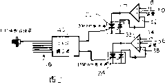
图2为光纤发射器的原理图;Fig. 2 is the schematic diagram of fiber optic transmitter;
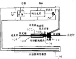
图3为光检测器单元的原理图;Fig. 3 is the schematic diagram of photodetector unit;
图4为一接头的剖面图;Figure 4 is a sectional view of a joint;
图5为水分探测传感器装置的剖面图;Fig. 5 is the sectional view of moisture detection sensor device;
图6为表示光纤接头耦合损耗相对于光纤端头偏移的曲线图;Fig. 6 is a graph representing the coupling loss of the optical fiber connector relative to the offset of the optical fiber end;
图7为光接收器的原理图;Figure 7 is a schematic diagram of the optical receiver;
图8为光检测器单元的一个替换实施例的示意图;Figure 8 is a schematic diagram of an alternative embodiment of a photodetector unit;
图9为表示光纤接头耦合损耗相对于光纤端头轴向分离的曲线图。Figure 9 is a graph showing the coupling loss of a fiber optic splice versus the axial separation of the fiber tip.
参见附图,特别是图1,示出了一个与纤维光缆12相关联的纤维光缆监测系统10。所示的光缆为一单模(sm)光缆,其长度高达100Km。所示的光缆包括一个沿其长度方向上的接头14部分。通常,一根完整的电缆会包含很多接头。该光缆包括很多根光纤16。Referring to the drawings, and in particular FIG. 1 , a fiber optic
系统10包括在电缆一端的光发射器单元18和在另一端的光接收器20。最特别地如图2所示,光发射器为一个双波长激光发射器,它包括一个发射波长为1300nm的光的稳定激光源22和发射波长为1550nm的光的第二稳定激光源24。激光源22与一调制放大器26相连接。至该放大器的输入包括带有偏置输入30、调制输入28和负反馈32。该调制输入具有频率F1,用以在该频率下调制被发射的1300nm光信号。激光器24同样与具有调制输入34、偏置输入36和负反馈38的放大器33相关联。调制信号F2的频率不同于调制频率F1。这些激光器配合成一个波分离多路复用耦合器40。该耦合器将激光器的光输出组合起来并将光能等量地分离至N个输出端口。这些输出端口的每一个上都连接有被监测光纤。随后,这一对激光器向几个被监测光纤或电缆提供光功率。
在光纤的接收端是一个光接收器20(图7),它在一个PIN检测二极管42上截取和检测来自每一被监测光纤的激光,所述的光由二极管转换成电信号,该电信号由前置放大器44放大。该电信号包含频率成分F1和F2,它们通过带通滤波器46和50被分离开来,并被测量电路48和52测量。通过测量的幅度来计算出在两个波长上光纤长度的光衰减。At the receiving end of the fiber is an optical receiver 20 (FIG. 7) that intercepts and detects laser light from each monitored fiber at a
光接收器也包括一个脉冲检测器54,用以监测在光检测器单元中产生的脉冲。该光检测器单元将在后面进行更详细的描述。The photoreceiver also includes a
光接收器的输出被送到多路复用器56,后者对来自各个被监测光纤的输出进行扫描,并向中央局终端58提供输入;中央局终端58包括报警电路58,用以在被检测的光纤衰减超出一预定最大衰减时发出警报。该终端还包括一个译码电路60,用以对来自脉冲检测器54的脉冲进行译码。The output of the optical receiver is sent to a
特别地参见图3、4和5,接头14包括一个调制器62,用于在由各光纤发射的光中产生脉冲以供脉冲检测器54检测。调制器包括一个带有V型槽66的接头64,V型槽66使通过电缆接头的被监测光纤的端头得以对准。在接头处,光纤端头70具有一连接于其顶面的很小的铁类金属元件72。它位于紧贴调制器电磁体74的一极之下。该铁磁体74电气地连接于水份探测传感器76和驱动晶体管80的集电极78之间。该晶体管80的发射极连接于水份探测传感器76而其基极84则连接于码发生器86,后者又连接到时钟88。码发生器和时钟均跨过水分探测传感器76的终端而连接。Referring particularly to FIGS. 3 , 4 and 5 ,
探测传感器76是一个具有延带长度延伸的镁导体92和铜导体94的一条一米长的带90。各导体均嵌于和粘贴于透水的PVC塑料隔离层之中。在两导体之间,将它们隔离的隔离材料96是硫酸铜的水溶性致电离层。在使用中,水分探测传感器带被缠绕于接头托架97(图4)周围以构成接头。如果水份渗入接头盒,水将溶解电解质盐,产生电解质,激励该传感器产生直流电压。传感器组分的分离保证了在干燥状态下的基本上无限长的寿命,该传感器然后便起到一个电池的作用,驱动时钟、码发生器、驱动器和调制器电磁体。驱动器在时钟和码发生器控制下向电磁体提供码电流脉冲。电磁体线圈中的电流脉冲建立起磁脉冲,它们吸引连接于光纤端头70上的铁磁体部件72,因而推动该光纤端头失去与光纤端头68的对准。如图6所示,光纤端头在5微米数量级上或更多的非对准就将明显地降低耦合的光能量,并产生一种由码发生器所确定的速率下的调幅脉冲流。The
将125微米的玻璃纤维致偏5到10微米所需要的能量是非常少的。这些检测器电路被设计成采用低电压微瓦CMOS集成电路。结果,一米长的单个传感器电池能够向调制器和有关的一些电路供电几个星期。从而保证了对湿的接头的检测。The energy required to deflect a 125 micron glass fiber by 5 to 10 microns is very small. These detector circuits are designed using low voltage microwatt CMOS integrated circuits. As a result, a single sensor battery one meter long can power the modulator and some of the associated circuitry for several weeks. Detection of wet joints is thus guaranteed.
如前所述,光接收器截取和检测来自被监测光纤的激光,并将其转换成一个电信号。由脉冲检测器54检测的脉冲在译码电路中被译码,以辨别出现脉冲的接头件。为些目的,对于每一接头件的码发生器86将产生一个独有的脉冲信号。As mentioned earlier, the optical receiver intercepts and detects the laser light from the fiber being monitored and converts it into an electrical signal. The pulses detected by the
两种监测信号波长下的整个光纤上的光衰减是通过测量的每一转换电信号的幅度来计算的。任何超过额定的附加光纤衰减都得到分析。The optical attenuation across the fiber at the two monitor signal wavelengths is calculated from the measured amplitude of each converted electrical signal. Any additional fiber attenuation above rating is analyzed.
如果在两种波长下测得类似的衰减增大,那么这种衰减增大可以认为是由微弯曲造成的,它可能是由于电缆挤压或与温度相关的电缆结构改变而引起的。如果仅在1550nm下检测到明显的衰减增大,问题则可能会与宏弯曲有关,这通常是由于电缆的绞结或光纤的折损而引起的。If a similar increase in attenuation is measured at both wavelengths, then this increase in attenuation can be assumed to be due to microbending, which may be caused by cable extrusion or temperature-related structural changes in the cable. If a noticeable increase in attenuation is only detected at 1550nm, the problem may be related to macrobending, which is usually caused by kinks in the cable or breaks in the fiber.
光检测器的一个替换实施例示于图8。该实施例不同于图3所示实施例之处在于调制器采用了毛细管式的接头100,在该接头中,光纤端头在套管102中对准。光纤一端104固定,另一端可运动但由弹簧向固定端施加偏压。一个铁类套管108固定在光纤的可运动端。调制器线圈110围绕于邻接套管108的光纤。在受激时,线圈将光纤端头106抽离光纤端头104,这样便对光纤上的信号进行调制。An alternative embodiment of a light detector is shown in FIG. 8 . This embodiment differs from the embodiment shown in FIG. 3 in that the modulator employs a capillary type connector 100 in which the fiber ends are aligned in a
耦合损耗相对于轴向光纤端头分离的曲线由图9给出。光纤运动是以这样一种幅度级别进行的,即大于产生同样的耦合损耗,所需要的偏移。A plot of coupling loss versus axial fiber tip separation is given in FIG. 9 . Fiber motion is performed at an amplitude level greater than the offset required to produce the same coupling loss.
调制器和相关的电和机械元件可能不便于安装到用在接头件中的接头托架或其它接头组件之中,那么可以利用托架背面或侧面的适当位置。Where the modulator and associated electrical and mechanical components may not be conveniently mounted into a connector bracket or other connector assembly used in a connector assembly, suitable locations on the back or side of the bracket may be utilized.
尽管以上描述了本发明的一个实施例,但应理解到,在本发明的范围内还能做出其它一些实施例。因此,例如,光检测器单元可以采用一些非如图中示出的电磁式那样的调制器。例如,可以用压电晶体或其它一些机电调制装置来将电脉冲改变为机械偏移和后续的耦合衰减。任何起光学开关作用的其它器件均可以采用。水份探测传感器可由选出的任何两种金属制成,只要在合适的电解质存在的情况下提供适当的半电解反应即可。因此应当理解到,不能认为本发明只限于所公开的特定实施例。本发明只为所附的权利要求书所限定。While one embodiment of the invention has been described above, it should be understood that other embodiments can also be made within the scope of the invention. Thus, for example, the photodetector unit may employ modulators other than the electromagnetic ones shown. For example, a piezoelectric crystal or some other electromechanical modulation device could be used to change the electrical pulse to a mechanical deflection and subsequent coupling decay. Any other device that functions as an optical switch can be used. Moisture detection sensors can be made from any two metals selected as long as they provide a suitable semi-electrolytic reaction in the presence of a suitable electrolyte. It should therefore be understood that the invention is not to be considered limited to the particular embodiments disclosed. The invention is limited only by the appended claims.
Claims (13)
Priority Applications (1)
| Application Number | Priority Date | Filing Date | Title |
|---|---|---|---|
| CN93104451A CN1046830C (en) | 1993-04-14 | 1993-04-14 | Fiber Optic Cable Monitoring System |
Applications Claiming Priority (1)
| Application Number | Priority Date | Filing Date | Title |
|---|---|---|---|
| CN93104451A CN1046830C (en) | 1993-04-14 | 1993-04-14 | Fiber Optic Cable Monitoring System |
Related Child Applications (1)
| Application Number | Title | Priority Date | Filing Date |
|---|---|---|---|
| CN99105287A Division CN1236234A (en) | 1999-04-30 | 1999-04-30 | Fiber optic cable monitoring system |
Publications (2)
| Publication Number | Publication Date |
|---|---|
| CN1093846A CN1093846A (en) | 1994-10-19 |
| CN1046830C true CN1046830C (en) | 1999-11-24 |
Family
ID=4985197
Family Applications (1)
| Application Number | Title | Priority Date | Filing Date |
|---|---|---|---|
| CN93104451A Expired - Fee Related CN1046830C (en) | 1993-04-14 | 1993-04-14 | Fiber Optic Cable Monitoring System |
Country Status (1)
| Country | Link |
|---|---|
| CN (1) | CN1046830C (en) |
Families Citing this family (4)
| Publication number | Priority date | Publication date | Assignee | Title |
|---|---|---|---|---|
| US7280769B2 (en) * | 2003-07-28 | 2007-10-09 | Emerson Electric Co. | Method and apparatus for operating an optical receiver for low intensity optical communication in a high speed mode |
| JP4009623B2 (en) * | 2004-08-16 | 2007-11-21 | 埼玉日本電気株式会社 | Wet detection seal, mobile phone and electronic device using the same |
| DE102006061164B4 (en) | 2006-12-22 | 2018-12-27 | Osram Opto Semiconductors Gmbh | Light-emitting device |
| CN111398201B (en) * | 2020-06-08 | 2020-09-22 | 翼捷安全设备(昆山)有限公司 | Optical Gas Detector |
Citations (1)
| Publication number | Priority date | Publication date | Assignee | Title |
|---|---|---|---|---|
| US5150243A (en) * | 1989-06-12 | 1992-09-22 | Fujitsu Limited | Method and apparatus for monitoring an optical network interface |
-
1993
- 1993-04-14 CN CN93104451A patent/CN1046830C/en not_active Expired - Fee Related
Patent Citations (1)
| Publication number | Priority date | Publication date | Assignee | Title |
|---|---|---|---|---|
| US5150243A (en) * | 1989-06-12 | 1992-09-22 | Fujitsu Limited | Method and apparatus for monitoring an optical network interface |
Also Published As
| Publication number | Publication date |
|---|---|
| CN1093846A (en) | 1994-10-19 |
Similar Documents
| Publication | Publication Date | Title |
|---|---|---|
| US5262639A (en) | Fiber optic cable monitoring method and apparatus including moisture detection and bending loss detection | |
| US6496629B2 (en) | Undersea telecommunications cable | |
| Bjerkan | Application of fiber-optic Bragg grating sensors in monitoring environmental loads of overhead power transmission lines | |
| EP3109958A1 (en) | Field control element for a high-voltage cable accessory and method of optically measuring partial discharges | |
| US20180371898A1 (en) | Fixed-wavelength fiber optic telemetry | |
| JP2008309497A (en) | Fiber optic sensor | |
| CN1093846A (en) | Fiber Optic Cable Monitoring System | |
| EP0635123B1 (en) | Moisture sensor, in particular for fiber optic cable monitoring system | |
| Fu et al. | A novel fiber Bragg grating sensor configuration for long-distance quasi-distributed measurement | |
| CN115586613A (en) | Multi-fiber-core optical cable based on optical fiber codes, and optical fiber code identification system and method | |
| CN101533133A (en) | Transmitting and sensing optical cable | |
| CA2237377C (en) | Fiber optic cable monitoring system | |
| CN201083536Y (en) | Optic cable vibration detecting device capable of positioning | |
| CN1236234A (en) | Fiber optic cable monitoring system | |
| CN107123477B (en) | Existing railway through ground wire anti-theft system based on optical fiber microbend design | |
| Nan et al. | Optical fiber sensing system for online monitoring wind-induced vibration on power transmission tower survey | |
| CN216819841U (en) | Optical fiber transmission vibration sensing device | |
| Rosolem et al. | Comparative analysis of fiber grating versus fiber powering for fiber optical sensing applications | |
| Clift | Composite fibre optic insulators and their application to high voltage sensor systems | |
| CN201307463Y (en) | Sensing optical cable | |
| CN121898586A (en) | Integrated optical energy transmission and vibration signal energy transmission method based on inclined grating optical fiber | |
| CN1095482A (en) | A kind of acceleration sensing method with optical fibre and equipment | |
| JPH0325381A (en) | Current detection system for overhead conductor | |
| Lynch | A 150 km Undersea Repeaterless Lightwave Transmission Link Operating at a 1.55 Micron Wavelength | |
| JPS61235737A (en) | Moisture detection method |
Legal Events
| Date | Code | Title | Description |
|---|---|---|---|
| C06 | Publication | ||
| PB01 | Publication | ||
| C10 | Entry into substantive examination | ||
| SE01 | Entry into force of request for substantive examination | ||
| C14 | Grant of patent or utility model | ||
| GR01 | Patent grant | ||
| C19 | Lapse of patent right due to non-payment of the annual fee | ||
| CF01 | Termination of patent right due to non-payment of annual fee |