CN105683050B - container device - Google Patents
container device Download PDFInfo
- Publication number
- CN105683050B CN105683050B CN201480058490.9A CN201480058490A CN105683050B CN 105683050 B CN105683050 B CN 105683050B CN 201480058490 A CN201480058490 A CN 201480058490A CN 105683050 B CN105683050 B CN 105683050B
- Authority
- CN
- China
- Prior art keywords
- container
- hinge
- side walls
- blank
- lid
- Prior art date
- Legal status (The legal status is an assumption and is not a legal conclusion. Google has not performed a legal analysis and makes no representation as to the accuracy of the status listed.)
- Expired - Fee Related
Links
Images


Classifications
-
- B—PERFORMING OPERATIONS; TRANSPORTING
- B65—CONVEYING; PACKING; STORING; HANDLING THIN OR FILAMENTARY MATERIAL
- B65D—CONTAINERS FOR STORAGE OR TRANSPORT OF ARTICLES OR MATERIALS, e.g. BAGS, BARRELS, BOTTLES, BOXES, CANS, CARTONS, CRATES, DRUMS, JARS, TANKS, HOPPERS, FORWARDING CONTAINERS; ACCESSORIES, CLOSURES, OR FITTINGS THEREFOR; PACKAGING ELEMENTS; PACKAGES
- B65D5/00—Rigid or semi-rigid containers of polygonal cross-section, e.g. boxes, cartons or trays, formed by folding or erecting one or more blanks made of paper
- B65D5/18—Rigid or semi-rigid containers of polygonal cross-section, e.g. boxes, cartons or trays, formed by folding or erecting one or more blanks made of paper by folding a single blank to U-shape to form the base of the container and opposite sides of the body portion, the remaining sides being formed primarily by extensions of one or more of these opposite sides, e.g. flaps hinged thereto
-
- B—PERFORMING OPERATIONS; TRANSPORTING
- B65—CONVEYING; PACKING; STORING; HANDLING THIN OR FILAMENTARY MATERIAL
- B65D—CONTAINERS FOR STORAGE OR TRANSPORT OF ARTICLES OR MATERIALS, e.g. BAGS, BARRELS, BOTTLES, BOXES, CANS, CARTONS, CRATES, DRUMS, JARS, TANKS, HOPPERS, FORWARDING CONTAINERS; ACCESSORIES, CLOSURES, OR FITTINGS THEREFOR; PACKAGING ELEMENTS; PACKAGES
- B65D5/00—Rigid or semi-rigid containers of polygonal cross-section, e.g. boxes, cartons or trays, formed by folding or erecting one or more blanks made of paper
- B65D5/02—Rigid or semi-rigid containers of polygonal cross-section, e.g. boxes, cartons or trays, formed by folding or erecting one or more blanks made of paper by folding or erecting a single blank to form a tubular body with or without subsequent folding operations, or the addition of separate elements, to close the ends of the body
-
- B—PERFORMING OPERATIONS; TRANSPORTING
- B65—CONVEYING; PACKING; STORING; HANDLING THIN OR FILAMENTARY MATERIAL
- B65D—CONTAINERS FOR STORAGE OR TRANSPORT OF ARTICLES OR MATERIALS, e.g. BAGS, BARRELS, BOTTLES, BOXES, CANS, CARTONS, CRATES, DRUMS, JARS, TANKS, HOPPERS, FORWARDING CONTAINERS; ACCESSORIES, CLOSURES, OR FITTINGS THEREFOR; PACKAGING ELEMENTS; PACKAGES
- B65D1/00—Rigid or semi-rigid containers having bodies formed in one piece, e.g. by casting metallic material, by moulding plastics, by blowing vitreous material, by throwing ceramic material, by moulding pulped fibrous material or by deep-drawing operations performed on sheet material
- B65D1/22—Boxes or like containers with side walls of substantial depth for enclosing contents
- B65D1/225—Collapsible boxes
-
- B—PERFORMING OPERATIONS; TRANSPORTING
- B65—CONVEYING; PACKING; STORING; HANDLING THIN OR FILAMENTARY MATERIAL
- B65D—CONTAINERS FOR STORAGE OR TRANSPORT OF ARTICLES OR MATERIALS, e.g. BAGS, BARRELS, BOTTLES, BOXES, CANS, CARTONS, CRATES, DRUMS, JARS, TANKS, HOPPERS, FORWARDING CONTAINERS; ACCESSORIES, CLOSURES, OR FITTINGS THEREFOR; PACKAGING ELEMENTS; PACKAGES
- B65D5/00—Rigid or semi-rigid containers of polygonal cross-section, e.g. boxes, cartons or trays, formed by folding or erecting one or more blanks made of paper
- B65D5/20—Rigid or semi-rigid containers of polygonal cross-section, e.g. boxes, cartons or trays, formed by folding or erecting one or more blanks made of paper by folding-up portions connected to a central panel from all sides to form a container body, e.g. of tray-like form
-
- B—PERFORMING OPERATIONS; TRANSPORTING
- B65—CONVEYING; PACKING; STORING; HANDLING THIN OR FILAMENTARY MATERIAL
- B65D—CONTAINERS FOR STORAGE OR TRANSPORT OF ARTICLES OR MATERIALS, e.g. BAGS, BARRELS, BOTTLES, BOXES, CANS, CARTONS, CRATES, DRUMS, JARS, TANKS, HOPPERS, FORWARDING CONTAINERS; ACCESSORIES, CLOSURES, OR FITTINGS THEREFOR; PACKAGING ELEMENTS; PACKAGES
- B65D5/00—Rigid or semi-rigid containers of polygonal cross-section, e.g. boxes, cartons or trays, formed by folding or erecting one or more blanks made of paper
- B65D5/36—Rigid or semi-rigid containers of polygonal cross-section, e.g. boxes, cartons or trays, formed by folding or erecting one or more blanks made of paper specially constructed to allow collapsing and re-erecting without disengagement of side or bottom connections
-
- B—PERFORMING OPERATIONS; TRANSPORTING
- B65—CONVEYING; PACKING; STORING; HANDLING THIN OR FILAMENTARY MATERIAL
- B65D—CONTAINERS FOR STORAGE OR TRANSPORT OF ARTICLES OR MATERIALS, e.g. BAGS, BARRELS, BOTTLES, BOXES, CANS, CARTONS, CRATES, DRUMS, JARS, TANKS, HOPPERS, FORWARDING CONTAINERS; ACCESSORIES, CLOSURES, OR FITTINGS THEREFOR; PACKAGING ELEMENTS; PACKAGES
- B65D5/00—Rigid or semi-rigid containers of polygonal cross-section, e.g. boxes, cartons or trays, formed by folding or erecting one or more blanks made of paper
- B65D5/42—Details of containers or of foldable or erectable container blanks
- B65D5/64—Lids
- B65D5/66—Hinged lids
- B65D5/6602—Hinged lids formed by folding one or more extensions hinged to the upper edge of a tubular container body
- B65D5/6605—Hinged lids formed by folding one or more extensions hinged to the upper edge of a tubular container body the lid being formed by two mating halves joined to opposite edges of the container body
-
- B—PERFORMING OPERATIONS; TRANSPORTING
- B65—CONVEYING; PACKING; STORING; HANDLING THIN OR FILAMENTARY MATERIAL
- B65D—CONTAINERS FOR STORAGE OR TRANSPORT OF ARTICLES OR MATERIALS, e.g. BAGS, BARRELS, BOTTLES, BOXES, CANS, CARTONS, CRATES, DRUMS, JARS, TANKS, HOPPERS, FORWARDING CONTAINERS; ACCESSORIES, CLOSURES, OR FITTINGS THEREFOR; PACKAGING ELEMENTS; PACKAGES
- B65D81/00—Containers, packaging elements, or packages, for contents presenting particular transport or storage problems, or adapted to be used for non-packaging purposes after removal of contents
- B65D81/38—Containers, packaging elements, or packages, for contents presenting particular transport or storage problems, or adapted to be used for non-packaging purposes after removal of contents with thermal insulation
- B65D81/3813—Containers, packaging elements, or packages, for contents presenting particular transport or storage problems, or adapted to be used for non-packaging purposes after removal of contents with thermal insulation rigid container being in the form of a box, tray or like container
- B65D81/3816—Containers, packaging elements, or packages, for contents presenting particular transport or storage problems, or adapted to be used for non-packaging purposes after removal of contents with thermal insulation rigid container being in the form of a box, tray or like container formed of foam material
Landscapes
- Engineering & Computer Science (AREA)
- Mechanical Engineering (AREA)
- Ceramic Engineering (AREA)
- Rigid Containers With Two Or More Constituent Elements (AREA)
- Stackable Containers (AREA)
- Containers Having Bodies Formed In One Piece (AREA)
- Cartons (AREA)
- Closures For Containers (AREA)
- Control And Other Processes For Unpacking Of Materials (AREA)
- Feeding, Discharge, Calcimining, Fusing, And Gas-Generation Devices (AREA)
Abstract
An expanded polystyrene container comprises a substantially flat blank having a plurality of regions including a bottom, sidewalls, end walls and a lid. The blanks are convertible to an unassembled first configuration in which regions of the blanks are pivoted relative to other regions about hinges connecting the other regions to form rectangular slabs, and a second configuration in which the blanks in the compact mode are stackable, the blanks erected to form containers having substantially uniform cross-sectional cubic configurations for storing articles. The hinge includes a recess defining a point of minimum cross-section. The bottom of the container may also include a ledge at each corner of the bottom that provides support for the hinge.
Description
Technical Field
The present invention relates generally to container devices and, more particularly, to container devices made from a single piece of material that is folded to form an assembled structure.
Background
In a continuously growing demand society, it remains an important requirement to provide packaging and containers to contain, transport and/or store a variety of items. Various proposals have been made for a long time to meet this requirement with some degree of success.
In this regard, cartons have proven to be a popular form of packaging for a number of reasons. The carton can be manufactured relatively inexpensively and can be easily formed into a blank that can be stored and transported in a flat form and can be simply folded to form the desired box. The carton can be made in a variety of sizes and can be reinforced to withstand a degree of force by using tape or fasteners as needed. However, due to the nature of the carton itself, which has limited durability and is particularly vulnerable to damage when exposed to liquids, shock or other types of handling, they can cause the carton to break and lose structural integrity.
With the widespread acceptance of plastic materials, such as Expandable Polystyrene (EPS), it has become possible to take advantage of these materials and their inherent properties to provide improved containers. EPS boxes have particular application in the storage and transport of perishable materials, such as agricultural and horticultural products, because they are to a large extent impermeable and therefore provide an environment for the stored items that can be temperature regulated in an air or water impermeable state. Because of the nature of EPS, boxes supported by EPS also have a degree of impact resistance, which can provide protection to materials stored or carried therein.
However, although materials such as EPS offer various advantages for packaging applications, boxes or packages made from such materials are formed as a single piece due to the manner in which EPS needs to be expanded and formed in a mold. While this is useful for protecting a dimensionally accurate end product, the resulting product occupies a volume even when empty, requiring space for storage when not in use and less economically stored and transported when empty. Therefore, these EPS boxes are often broken and packed after use and are no longer used.
A number of systems have been proposed for manufacturing EPS boxes in the form of flat slabs and assembling the boxes for use. This is typically accomplished by forming hinges in the EPS blank and/or applying pressure to specific areas of the blank during molding. A detailed description of this method is found in the applicant's International application No. PCT/AU 2010/000340.
While the above-described methods have proven effective in enabling boxes to be assembled from flat EPS blanks, there is a need for further improvements in EPS boxes formed in this manner to provide increased strength and storability when not in use or when shipped in an empty shell.
The above references to and descriptions of prior art schemes or products are not intended to, and should not be taken as, an assertion or admission of common general knowledge in the art. In particular, the above prior art discussion is not relevant to the knowledge of one skilled in the art, but is helpful in understanding the inventive steps of the present invention, and it is assumed that the relevant prior art solution is only a part.
Disclosure of Invention
One or more aspects of the invention are defined in the independent claims. Some optional and preferred features of the invention are defined in the dependent claims.
The present invention provides a container device, characterized in that: a substantially flat blank having a plurality of predetermined regions formed therein to define a base, side walls and end walls of said container, each of said plurality of predetermined regions being connectable to at least one other of said plurality of predetermined regions by hinges formed in said blank, said blank being adapted to be erected into a first configuration in which said blank forms said container means and a second configuration in which said blank forms a substantially rectangular body of substantially uniform cross-section for storing articles.
The present invention also provides a hinge for facilitating pivotal movement between integrally formed adjacent planar surfaces, wherein a recess is formed between said integrally formed adjacent planar surfaces, said recess defining a groove of minimum cross-section, said groove forming a pivot point about which pivotal movement between said planar surfaces is facilitated, such that opposing side walls of said recess interengage upon pivotal movement of said planar surfaces through an arc of each other, said interengagement comprising at least one stepped region of one of said side walls engaging a surface of the opposing side wall of said side wall.
The invention also provides a container blank comprising a base and a plurality of side walls, each of the plurality of side walls being connectable to the base by a hinge such that each of the plurality of side walls is pivotable about the respective hinge relative to the base to form the container, characterised in that the base is provided with a plurality of projections extending from the base to provide support for the hinges when the blank is erected to form the container.
Drawings
The invention will be more readily understood from the following non-limiting description of preferred embodiments, in which:
FIG. 1 shows a perspective view of an assembled container according to an embodiment of the present invention;
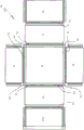
FIG. 2 is a top plan view of the container of FIG. 1 when unassembled;
FIG. 3 is a bottom plan view of the container of FIG. 1 when unassembled;
FIG. 4 is an assembled elevational view of the container of FIG. 1;
FIG. 5 is an assembled, elevational, cross-sectional view of the container of FIG. 1;
FIG. 6 is an end view of the container of FIG. 1 assembled;
FIG. 7 is a side cross-sectional view of the container of FIG. 1 assembled;
FIG. 8 shows an enlarged view of a hinge region according to an embodiment of the invention;
FIG. 9 is an enlarged view of the hinge area of FIG. 8 in an assembled state;
FIG. 10 shows a perspective view of an assembled container according to another embodiment of the invention;
FIG. 11 is a top plan view of the container of FIG. 10 when unassembled;
FIG. 12 is a side view of the container of FIG. 10 when unassembled;
FIG. 13 is a side view of the unassembled container in a compact mode for storage;
FIG. 14 is a perspective view of an assembled container according to an alternative embodiment of the present invention;
FIG. 15 is a top plan view of the container of FIG. 14 when unassembled; and
fig. 16 is a cross-sectional side view of the container of fig. 14 when unassembled.
Detailed Description
Preferred features and embodiments of the present invention will now be described with reference to the accompanying drawings. It is to be understood, however, that the features illustrated and described herein with reference to the drawings are not to be considered limiting of the scope of the present invention.
The present invention employs the method and tooling for forming a blank described in the applicant's earlier filed international application PCT/AU 2010/000340. Accordingly, the manner in which the blank is formed will not be described in detail herein.
In the following description, the application of the invention to a box made of EPS is described. It will be appreciated that the concepts of the present invention may be used to form various other types of structures made of EPS or similar materials, such as mats used in construction, ducts used in air conditioning, etc., as well as other combinations not presently contemplated.
Referring to FIG. 1, a container 10 is shown according to an embodiment of the present invention. The container 10 is in the form of a blank that is assembled into a rectangular box with a lid 12, opposed side walls 14 and opposed end walls (end walls) 16. The bottom 18 forms the bottom of the container 10 such that the interior of the container represents an enclosed space in which items may be stored or contained.
The container 10 is preferably made of EPS and has a lid 12, side walls 14, end walls 16 and a base 18, which have a maximum thickness of 20-30 mm (millimetres), preferably about 25 mm. However, other thicknesses are possible.
As shown with reference to fig. 2 and 3, the container 10 is formed from a substantially flat blank. A plurality of hinges 20 are formed at the intersection of the lid 12, side walls 14 and end walls 16 and the base 18 to facilitate bending of the lid 12, side walls 14, end walls 16 and base 18 to the position shown in fig. 1. As shown, hinges 20 are formed on the interior surface of the blank, the manner in which the hinges 20 are provided being described in detail below.
To facilitate assembly of the various parts of the blank, each side wall 14 includes a groove or recess 22 formed in either end of the side wall 14, the groove or recess 22 extending perpendicular to the hinge 20 connecting the side wall 14 to the base 18 and extending substantially the height of the side wall 14, as best seen in fig. 2. The upper edge 14a of each side wall 14, i.e., the edge of the side wall 14 opposite and parallel to the hinge 20 connecting the side wall 14 to the base 18, has a lip 24 formed thereon. The lip 24 extends between the grooves or recesses 22 formed at the opposite ends of the side wall 14 and comprises a continuation of the side wall 14 having a reduced thickness relative to the remainder of the side wall 14. In a preferred form, the lip 24 extends about 7mm past the upper edge 14a of the side wall and has a thickness of about 9-10 mm, while the remainder of the side wall has a thickness of about 20 mm.
Each end wall 16 is connected along a lower edge to the bottom 18 by a hinge 20 and along an upper edge to a portion of the lid 12 by another hinge 20. The free end 16a of the end wall, i.e. the end extending between the hinges 20 and orthogonal to the hinges 20, is also provided with a rib 26, as shown in figure 2, which extends in a continuous manner over the free end 16 a. The rib 26 acts in a similar manner on the lip 24 of the side wall 14 and comprises a continuation of the end wall 16 having a reduced thickness compared to the remainder of the end wall 16. In a preferred form, the rib 26 extends about 7mm past the free end 16a of the end wall and has a thickness of about 9-10 mm, with the remainder of the end wall having a thickness of about 20 mm.
As shown in fig. 1, the cover 12 includes two substantially identical cover assemblies 12a and 12 b. Each of the lid assemblies 12a and 12b has a recess 28 formed along opposite sides thereof that extends perpendicular to the hinge 20 connecting the lid assemblies 12a and 12b to the respective end walls 16. The grooves 28 function in the same manner as the grooves or flutes 22 formed at either end of the side walls 14, the purpose of which will be described in detail below.
Each of the free ends 12c and 12d of the cap assemblies 12a and 12b are configured to interconnect when assembled to facilitate sealing of the cap 12, as shown in fig. 1. In this regard, the free end 12c of the cap assembly 12a has a stepped region formed thereon having a reduced thickness relative to the remaining region of the cap assembly 12 a. The stepped surface of the free end 12c has one or more projections 29a extending therefrom. The projection 29a is preferably formed as part of the molding process and made of EPS, although other materials are possible. To facilitate engagement between the cap assemblies 12a and 12b, the free end 12d of cap assembly 12b also has a stepped region formed thereon that substantially matches the stepped region formed at the free end 12c of the cap assembly 12a when the cap assemblies 12a and 12b are brought together. As best seen in fig. 3, the outer surface of the stepped region of the free end 12d has one or more projections 29a configured to matingly form on the stepped region of the free end 12c, thereby providing engagement between the cap assemblies 12a and 12b to close the caps when the container 10 is assembled in the manner shown in fig. 1.
Referring to fig. 5, the manner in which the end walls 16 and side walls 14 mate to form the assembled container 10 is illustrated. The end wall 16 is first folded through a 90 arc to a vertical position. The side wall 16 is then folded through a 90 deg. arc to an upright position relative to the base 18 so that the ribs 26 of the side wall 16 are received within the grooves or recesses 22 formed in the side wall 14. The ribs 26 may have a width greater than the width of the groove or recess 16 to promote a degree of interference fit therebetween to provide a degree of positive engagement between the side wall 14 and the end wall 16 in the upright position as shown in fig. 6.
Once the side walls 14 and end walls 16 are in the upright position, the lid assemblies 12a and 12b can be lowered into position to extend through the open container 10 and close the space contained therein. In this regard, the side wall 16 is in an upright position, with the lip 24 extending over its upper edge 14 a. A groove 28 extending along opposite sides of the lid assemblies 12a and 12b can be positioned such that the lip 24 is received within the groove 28 to provide a positive engagement between the lid assemblies 12a and 12b and the side wall 14, which increases the strength of the container and creates a seal around the container 10.
It should be understood that the lid 12 of the container 10 may be omitted. Many consumers of the type of containers described in this specification desire open top containers. In this arrangement, the erected container 10 is an open-top container absent the lid 12 or lid assemblies 12a and 12b, which may be closed by trapping or tying, which preferably wraps around the side walls 14 to increase the strength of the erected container. The preferred type of binding is a plastic film commonly used to bundle things. Alternatively, the lid assemblies 12a and 12b may be vestigial (vestigial), locked into the side walls 14 to create a strong erected container 10, but when the erected container is substantially open. Alternatively, there is a one-piece lid 12 hingedly connected to one side wall 14 and adapted to interconnect with the other side wall to form an upright container.
Referring to fig. 7-9, the manner in which the hinge 20 is provided is shown. The hinge 20 functions to provide pivotal movement between the various parts of the container 10 to enable the container 10 to be formed from a flat sheet form into a box form. As previously discussed, the hinge formation process is described in applicant's earlier filed international application PCT/AU2010/000340 and will not be described in detail herein.
Each hinge 20 is shaped to define a pivot point 30 about which the respective portion of the blank (in this case portions 72, 74) can be folded. A V-shaped groove 32 is formed in the body of the blank so that the part of the V-shaped groove is the same, i.e. preferably at 45 °, on either side of the pivot point 30. Two complementary angles may also be used. Pivot point 30 includes a recess at the bottom of V-groove 32, which is the narrowest region of material 76 that connects portions 72 and 74. Once the pivot point 30 is formed, it defines an axis about which the hinge 20 folds. The purpose of the recess 32 is to enhance the ability of the hinge 20 to fold back on itself and to fold in the opposite direction when the container 10 is erected, as discussed further below.
The hinge is shaped other than as a V so that the material provided on either side of the hinge point 30 is shaped as a mirror image, with the material shaped differently on each side of the hinge point to increase the strength of the hinge 20. Where the V-shaped groove 32 ends, on the side of the portion 72 of the hinge point, the V-shaped groove 32 ends in a vertical wall 33, and on the side of the other portion 74 of the hinge point, the V-shaped groove 32 ends in a horizontally extending stepped region 34, which ends in a vertical wall 35.
As best shown in fig. 9, as the hinge 20 moves, pivoting in a clockwise direction from the horizontal arrangement shown in fig. 8 to the exemplary 90 ° arrangement of fig. 9, the respective faces of the hinge 20 mesh together on either side of the pivot point 30. In this regard, the horizontally extending stepped region 34 of the hinge 20 on one side of the pivot point 30 abuts the vertical wall 33 of the hinge on the other side of the pivot point 30, and the vertical wall 35 falls on the upper surface of the blank. Such an arrangement ensures that any downward force exerted on the container 10 during assembly, such as may occur when stacking a plurality of containers upward, will act in the direction of arrow a. Since the hinge 20 comprises a stepped area and not only two 45 deg. surfaces, the shear forces present on the hinge as a result of the pressure in the direction of arrow a are significantly reduced. As shown in fig. 7, by providing a hinge 20 at each corner of the container 10, the compressive strength of the container is significantly increased.
The hinge 20 of fig. 7-9 may also be operated in the opposite direction. The blank portion 74 may be rotated in a counterclockwise direction from the position depicted in fig. 7 to an exemplary 90 deg. arrangement in which the wall 35 would abut the wall 78 of the portion 72. In the same manner, downward forces on portion 74 are resisted by wall 78 of portion 72.
Referring to fig. 10 and 11, an alternative embodiment of a container 10 according to the present invention is shown. This embodiment is similar to the embodiment shown in fig. 1-9, except that additional hinges 20 are included in the lid assemblies 12a and 12b, respectively.
As shown in fig. 11, each lid assembly 12a and 12b includes an additional hinge 20 to enable the lid assemblies 12a and 12b to be opened without breaking the joint between the lid assemblies 12a and 12b and the side wall 14. In this regard, the cover assemblies 12a and 12b are positioned in the manner described above such that the lip 24 of the side wall 14 is received within the channel 28 formed on the underside of the cover assemblies 12a and 12 b.
By providing an additional hinge 20 on each lid assembly, as shown by hinge line 42 in fig. 10, each of the lid assemblies 12a and 12B may be opened in the direction of arrow B to facilitate loading/unloading of the container 10, in doing so, the portion 40 of each of the lid assemblies 12a and 12B remains stationary. Since the portion 40 of each of the lid assemblies 12a and 12b remains stationary, the portion 40 provides a positive engagement with the side wall 14, thereby ensuring that the integrity of the assembled box is maintained and that the wall 14 remains in an upright position.
The embodiment of the container 10 described above provides a more robust and easily installed container that can be ideally loaded/unloaded, and the container of the present invention also provides a considerable improvement in stacking/storing blanks when not in use.
Fig. 12 shows a side view of the blank of fig. 11 in an expanded state. As shown, because the hinges 20 are formed on the upper (or inner) surface of the blank, they can be folded about 270 ° to facilitate compact storage. In this regard, as shown in fig. 13, by folding the side walls 14 under the bottom 18 and the lid assemblies 12a and 12b under the end walls 16, the blank 10 can be formed into a substantially rectangular slab, which can be categorized as a "compact mode," defined by the combined surfaces of the end walls 16 and the bottom 18, having a uniform thickness. Therefore, the unused or unassembled/disassembled blank 10 can be stacked in a convenient and simple manner, ensuring that no waste of space results.
Fig. 14-16 illustrate an alternative embodiment of the present invention. In this embodiment, a container 50 according to one embodiment of the present invention is shown. The container 50 is in the form of a blank. The blanks are assembled into a rectangular box having a lid portion 52, opposed side walls 54 and opposed end walls 56. The bottom 58 is formed below the container 50 such that the interior of the container represents an enclosed space within which items can be stored or contained when desired.
The container 50 is preferably made of EPS and has a lid 52, side walls 54, end walls 56 and a base 58 which are between 20-30 mm, preferably about 25mm, in maximum thickness. However, other thicknesses are possible.
As shown in fig. 15, the container 50 is formed from a substantially flat blank. A plurality of hinges 70 are formed at the junctions of cover 52, side walls 54, end walls 56 and bottom 58 to facilitate bending of cover 52, side walls 54, end walls 56 and bottom 58 to the position shown in fig. 14. As shown, a hinge 70 is formed on the interior surface of the blank, the hinge 70 being arranged in substantially the same manner as the hinge 20 described with reference to the previous embodiment, the main difference being that the hinge 70 is arranged in the reverse manner. This can be seen by comparing the hinge 70 of fig. 16 with the hinge 20 shown in fig. 9. It should be noted that although the orientation between hinges 20 and 70 is changed, the principle between the hinges is still comparable, and the opposite horizontal support area of the hinges acts to support the weight of the hinges, thereby reducing the pressure presented to the angled surfaces of the hinges.
Referring to fig. 15, the blank of this embodiment also includes a plurality of projections 60, which are material located in substantially flat areas at each corner of the base 58. As shown, the hinge 70 does not extend into the protruding region 60.
As shown in fig. 15, in use, the plurality of projections 60 act as hinges that support each corner of the bottom of the assembled container 50. The corners rest on the ledges 60 when the side walls 54 are folded about the hinges 70 to form the container 50. Since the bottom corners of the assembled container 50 are the critical load bearing points for the container, the provision of the projections 60 provides a degree of protection for the hinge 70 in these areas and provides a degree of impact resistance when the assembled container is dropped and the corners collide with hard surfaces. In addition, the provision of the projections 60 serves to divide the bottom hinge 70 into four separate regions, which enhances the ability to mold the blank and design tools during manufacture.
It will be appreciated that the resulting container 50, like the container 10, provides a strong, sturdy container that can be made of EPS, stacked in a flat manner when not in use and assembled in a simple, efficient, folding manner when in use.
The projection 60 may be provided elsewhere on the base 58 to support the hinge 70. Such projections may be located above the base 58 and extend from the base 58, below the hinge 70, and between the corners of the base 58, whether or not projections are provided at these corners.
Fig. 16 is a cross-sectional side view of the assembled container of fig. 14, showing a different hinge arrangement between the bottom 58 and the side 54 and between the lid assemblies 52a, 52b and the side walls 56. Preferably, the hinge arrangement at the upper portion of the container 50 is the same as that shown at the bottom of the container 50, in a manner similar to that shown in figure 7.
Throughout the specification and claims, the term "comprise" and its derivatives are intended to be open-ended rather than closed-ended unless explicitly stated or the context requires otherwise. That is, the term "comprises/comprising" and its derivatives, are intended to mean not only the listed components, steps or features but also other components, steps or features not expressly listed, unless expressly stated or the context requires otherwise.
It will be appreciated that various changes and modifications can be made by those skilled in the art to the method of the invention described herein without departing from the spirit and scope of the invention.
The specification, claims and drawings of australian provisional patent application 2013904133 filed on 25/10/2013 and australian provisional patent application 2014901686 filed on 7/5/2014 are hereby incorporated herein in their entirety.
Claims (9)
Applications Claiming Priority (5)
| Application Number | Priority Date | Filing Date | Title |
|---|---|---|---|
| AU2013904133A AU2013904133A0 (en) | 2013-10-25 | Container Apparatus | |
| AU2013904133 | 2013-10-25 | ||
| AU2014901686A AU2014901686A0 (en) | 2014-05-07 | Container apparatus | |
| AU2014901686 | 2014-05-07 | ||
| PCT/AU2014/001004 WO2015058246A1 (en) | 2013-10-25 | 2014-10-24 | Container apparatus |
Publications (2)
| Publication Number | Publication Date |
|---|---|
| CN105683050A CN105683050A (en) | 2016-06-15 |
| CN105683050B true CN105683050B (en) | 2020-05-12 |
Family
ID=52992044
Family Applications (1)
| Application Number | Title | Priority Date | Filing Date |
|---|---|---|---|
| CN201480058490.9A Expired - Fee Related CN105683050B (en) | 2013-10-25 | 2014-10-24 | container device |
Country Status (20)
| Country | Link |
|---|---|
| US (1) | US9873540B2 (en) |
| EP (1) | EP3060488B1 (en) |
| JP (2) | JP2016533984A (en) |
| KR (1) | KR102282249B1 (en) |
| CN (1) | CN105683050B (en) |
| AU (1) | AU2014339753B2 (en) |
| BR (1) | BR112016009128B1 (en) |
| CA (2) | CA3101247A1 (en) |
| DK (1) | DK3060488T3 (en) |
| EA (1) | EA037180B1 (en) |
| ES (1) | ES2767098T3 (en) |
| HR (1) | HRP20200047T1 (en) |
| HU (1) | HUE047270T2 (en) |
| MX (1) | MX383181B (en) |
| PH (1) | PH12016500769B1 (en) |
| PL (1) | PL3060488T3 (en) |
| PT (1) | PT3060488T (en) |
| RS (1) | RS59785B1 (en) |
| SI (1) | SI3060488T1 (en) |
| WO (1) | WO2015058246A1 (en) |
Families Citing this family (11)
| Publication number | Priority date | Publication date | Assignee | Title |
|---|---|---|---|---|
| GB201205243D0 (en) | 2012-03-26 | 2012-05-09 | Kraft Foods R & D Inc | Packaging and method of opening |
| GB2511560B (en) | 2013-03-07 | 2018-11-14 | Mondelez Uk R&D Ltd | Improved Packaging and Method of Forming Packaging |
| GB2511559B (en) | 2013-03-07 | 2018-11-14 | Mondelez Uk R&D Ltd | Improved Packaging and Method of Forming Packaging |
| KR102223604B1 (en) * | 2014-08-12 | 2021-03-05 | 아이씨이이 홀딩스 피티와이, 리미티드 | System and method for creating a fold in a portion of expandable material |
| DE102016112854A1 (en) * | 2016-07-13 | 2018-01-18 | Bs Systems Gmbh & Co. Kg | Stackable system tray |
| CN107336891B (en) * | 2017-06-13 | 2019-07-23 | 东莞市润信礼品包装有限公司 | A kind of hinge-lid pack |
| US20190315541A1 (en) * | 2018-04-16 | 2019-10-17 | Craft Packaging LLC | Insulated package |
| IT201900007020A1 (en) * | 2019-05-20 | 2020-11-20 | Bazzica Eng S R L | METHOD AND MOLD FOR THE MOLDING OF A FOLDABLE CONTAINER IN EXPANDED PLASTIC MATERIAL, AND CONTAINER SO OBTAINED |
| EP4048595A1 (en) * | 2019-10-25 | 2022-08-31 | Storopack Hans Reichenecker GmbH | Foldable box |
| DE112021000846T5 (en) * | 2020-02-05 | 2022-12-01 | Lifoam Industries, Llc | Biodegradable insulating structures, assemblies and associated methods of making such structures |
| CN116767632A (en) * | 2023-07-17 | 2023-09-19 | 厦门莱蔓新材料科技有限公司 | Plastic box body and preparation method thereof |
Citations (6)
| Publication number | Priority date | Publication date | Assignee | Title |
|---|---|---|---|---|
| DE7807151U1 (en) * | 1978-03-09 | 1979-07-12 | Smit Johan Jan Abraham Theodor | Fold-out delivery box for fish, for example |
| US4235346A (en) * | 1979-09-19 | 1980-11-25 | Joseph Liggett | Collapsible lightweight shipping container |
| EP1010625A1 (en) * | 1998-12-07 | 2000-06-21 | FEBRA-Kunststoffe GmbH & Co. | Packaging container made of foam material |
| US20040159659A1 (en) * | 2002-01-23 | 2004-08-19 | Donald Rumpel | Folding crate with array connection features |
| WO2009025627A1 (en) * | 2007-08-20 | 2009-02-26 | Odesa Gelistirilmis Polimer Yatirimlari Ve Dis Ticaret A.S. | Sliding lock mechanism for foldable transporting and stocking crates |
| CN102395512A (en) * | 2009-04-03 | 2012-03-28 | 加蒙德有限公司 | Improved containers |
Family Cites Families (15)
| Publication number | Priority date | Publication date | Assignee | Title |
|---|---|---|---|---|
| US3675808A (en) * | 1970-06-26 | 1972-07-11 | Delbert L Brink | Knockdown foamed plastic shipping container |
| GB1361501A (en) * | 1971-07-23 | 1974-07-24 | Standard Telephones Cables Ltd | Foamed plastics articles |
| US4010865A (en) * | 1974-11-11 | 1977-03-08 | Wilgus James L | Collapsible insulated box |
| US4170313A (en) | 1977-12-29 | 1979-10-09 | Caves Robert B | Box and blank for forming the box |
| GB2138782A (en) | 1983-04-29 | 1984-10-31 | Halsey Colin Denis | Foldable blank for container |
| FI860654A7 (en) * | 1985-02-21 | 1986-08-22 | Sekisui Plastics | LAODABILDANDE HOERNELEMENT OCH EN LAODA INNEHAOLLANDE ETT SAODANT. |
| JPS6315152Y2 (en) * | 1985-04-05 | 1988-04-27 | ||
| JPH04100430U (en) * | 1991-01-25 | 1992-08-31 | ||
| WO1992018392A1 (en) * | 1991-04-11 | 1992-10-29 | Midwest Plastic Fabricators, Inc. | Foldable electrical component enclosures |
| JPH05139441A (en) | 1991-11-08 | 1993-06-08 | Kanegafuchi Chem Ind Co Ltd | Foam synthetic resin assembly box |
| GB2286385B (en) * | 1994-02-11 | 1997-08-20 | Polystyrene Box Limited | Improvements in or relating to a collapsible container |
| DE19512823C5 (en) * | 1995-04-05 | 2004-11-04 | Verwaltungsgesellschaft Geiger Technik Gmbh & Co. Kg | Foldable packaging box |
| ES1041715Y (en) * | 1999-01-12 | 1999-11-16 | Romeu Juan Luis Ripolles | FOLDING BOX. |
| JP2003267346A (en) * | 2002-03-11 | 2003-09-25 | Tohoku Epe:Kk | Setup type heat-reserving returnable box |
| US8579778B2 (en) * | 2010-05-14 | 2013-11-12 | Rock-Tenn Shared Services, Llc | Machine and method for forming reinforced polygonal containers from blanks |
-
2014
- 2014-10-24 HR HRP20200047TT patent/HRP20200047T1/en unknown
- 2014-10-24 HU HUE14855141A patent/HUE047270T2/en unknown
- 2014-10-24 EA EA201600345A patent/EA037180B1/en unknown
- 2014-10-24 ES ES14855141T patent/ES2767098T3/en active Active
- 2014-10-24 PL PL14855141T patent/PL3060488T3/en unknown
- 2014-10-24 EP EP14855141.9A patent/EP3060488B1/en active Active
- 2014-10-24 RS RS20200045A patent/RS59785B1/en unknown
- 2014-10-24 BR BR112016009128-0A patent/BR112016009128B1/en not_active IP Right Cessation
- 2014-10-24 DK DK14855141.9T patent/DK3060488T3/en active
- 2014-10-24 CN CN201480058490.9A patent/CN105683050B/en not_active Expired - Fee Related
- 2014-10-24 CA CA3101247A patent/CA3101247A1/en not_active Abandoned
- 2014-10-24 SI SI201431447T patent/SI3060488T1/en unknown
- 2014-10-24 PT PT148551419T patent/PT3060488T/en unknown
- 2014-10-24 AU AU2014339753A patent/AU2014339753B2/en active Active
- 2014-10-24 US US15/032,030 patent/US9873540B2/en active Active
- 2014-10-24 KR KR1020167013885A patent/KR102282249B1/en active Active
- 2014-10-24 CA CA2928433A patent/CA2928433C/en not_active Expired - Fee Related
- 2014-10-24 JP JP2016549598A patent/JP2016533984A/en active Pending
- 2014-10-24 WO PCT/AU2014/001004 patent/WO2015058246A1/en not_active Ceased
- 2014-10-24 MX MX2016005271A patent/MX383181B/en unknown
-
2016
- 2016-04-25 PH PH12016500769A patent/PH12016500769B1/en unknown
-
2019
- 2019-09-13 JP JP2019166801A patent/JP6955776B2/en active Active
Patent Citations (6)
| Publication number | Priority date | Publication date | Assignee | Title |
|---|---|---|---|---|
| DE7807151U1 (en) * | 1978-03-09 | 1979-07-12 | Smit Johan Jan Abraham Theodor | Fold-out delivery box for fish, for example |
| US4235346A (en) * | 1979-09-19 | 1980-11-25 | Joseph Liggett | Collapsible lightweight shipping container |
| EP1010625A1 (en) * | 1998-12-07 | 2000-06-21 | FEBRA-Kunststoffe GmbH & Co. | Packaging container made of foam material |
| US20040159659A1 (en) * | 2002-01-23 | 2004-08-19 | Donald Rumpel | Folding crate with array connection features |
| WO2009025627A1 (en) * | 2007-08-20 | 2009-02-26 | Odesa Gelistirilmis Polimer Yatirimlari Ve Dis Ticaret A.S. | Sliding lock mechanism for foldable transporting and stocking crates |
| CN102395512A (en) * | 2009-04-03 | 2012-03-28 | 加蒙德有限公司 | Improved containers |
Also Published As
Similar Documents
| Publication | Publication Date | Title |
|---|---|---|
| CN105683050B (en) | container device | |
| US9096349B2 (en) | Divider boxes and their assembly | |
| EP3348493A1 (en) | Thermal container for bottles | |
| US7648031B2 (en) | Insert for protecting a product within a box | |
| GB2513106A (en) | Packaging | |
| JP4880454B2 (en) | Transport container system especially for commodities such as fruits and vegetables | |
| KR102088108B1 (en) | Packaging box having a buffer function against external impact | |
| KR20150083717A (en) | A foldable packaging box comprising hinge parts | |
| WO2017049338A1 (en) | Multi-compartmental foldable container | |
| WO2017078514A1 (en) | A reinforced corner carton | |
| CA2762757A1 (en) | Nestable rigid u-crates | |
| US10717563B2 (en) | Reusable bulk-sized shipping box | |
| JP2000355323A (en) | Assembling and folding storing box | |
| KR200477161Y1 (en) | Packing box reinforced the around edge | |
| JP2005053578A (en) | Container for packaging and transport | |
| JP2006306483A (en) | Folding-type synthetic resin-made box | |
| CA2754727C (en) | Four-sided container | |
| US20070007160A1 (en) | Box | |
| KR200311740Y1 (en) | The canton box a pileable up on the box | |
| KR20040005600A (en) | Packaging structure and packaging materials | |
| KR20200092675A (en) | Packing box | |
| JPH10324391A (en) | Folding type heat insulated container | |
| JP2005306432A (en) | Article storage case | |
| JP2002173139A (en) | A foldable distribution container for transporting fresh foods. |
Legal Events
| Date | Code | Title | Description |
|---|---|---|---|
| C06 | Publication | ||
| PB01 | Publication | ||
| C10 | Entry into substantive examination | ||
| SE01 | Entry into force of request for substantive examination | ||
| GR01 | Patent grant | ||
| GR01 | Patent grant | ||
| CF01 | Termination of patent right due to non-payment of annual fee |
Granted publication date: 20200512 |
|
| CF01 | Termination of patent right due to non-payment of annual fee |