CN105726112B - Orthopaedic implant and fastening assembly - Google Patents
Orthopaedic implant and fastening assembly Download PDFInfo
- Publication number
- CN105726112B CN105726112B CN201610086929.XA CN201610086929A CN105726112B CN 105726112 B CN105726112 B CN 105726112B CN 201610086929 A CN201610086929 A CN 201610086929A CN 105726112 B CN105726112 B CN 105726112B
- Authority
- CN
- China
- Prior art keywords
- hole
- nail
- screw
- compression
- intramedullary nail
- Prior art date
- Legal status (The legal status is an assumption and is not a legal conclusion. Google has not performed a legal analysis and makes no representation as to the accuracy of the status listed.)
- Active
Links
- 239000007943 implant Substances 0.000 title claims abstract description 22
- 230000006835 compression Effects 0.000 abstract description 121
- 238000007906 compression Methods 0.000 abstract description 121
- 210000000988 bone and bone Anatomy 0.000 description 36
- 210000000689 upper leg Anatomy 0.000 description 23
- 208000010392 Bone Fractures Diseases 0.000 description 15
- 230000007704 transition Effects 0.000 description 14
- 239000011800 void material Substances 0.000 description 9
- 238000005452 bending Methods 0.000 description 8
- 238000003780 insertion Methods 0.000 description 8
- 230000037431 insertion Effects 0.000 description 8
- 210000002758 humerus Anatomy 0.000 description 7
- 238000000034 method Methods 0.000 description 7
- 230000008901 benefit Effects 0.000 description 6
- 239000000463 material Substances 0.000 description 6
- 208000008924 Femoral Fractures Diseases 0.000 description 5
- 230000000712 assembly Effects 0.000 description 5
- 238000000429 assembly Methods 0.000 description 5
- 230000000295 complement effect Effects 0.000 description 5
- 210000001624 hip Anatomy 0.000 description 5
- 230000007246 mechanism Effects 0.000 description 5
- 230000000694 effects Effects 0.000 description 4
- 230000017531 blood circulation Effects 0.000 description 3
- 230000008685 targeting Effects 0.000 description 3
- 210000002303 tibia Anatomy 0.000 description 3
- 229920002593 Polyethylene Glycol 800 Polymers 0.000 description 2
- 230000009286 beneficial effect Effects 0.000 description 2
- 230000001054 cortical effect Effects 0.000 description 2
- 238000013461 design Methods 0.000 description 2
- 210000002436 femur neck Anatomy 0.000 description 2
- 230000006870 function Effects 0.000 description 2
- 208000031074 Reinjury Diseases 0.000 description 1
- 208000027418 Wounds and injury Diseases 0.000 description 1
- 210000000588 acetabulum Anatomy 0.000 description 1
- 230000001154 acute effect Effects 0.000 description 1
- 238000011882 arthroplasty Methods 0.000 description 1
- 150000001875 compounds Chemical class 0.000 description 1
- 230000008878 coupling Effects 0.000 description 1
- 238000010168 coupling process Methods 0.000 description 1
- 238000005859 coupling reaction Methods 0.000 description 1
- 230000006378 damage Effects 0.000 description 1
- 230000006866 deterioration Effects 0.000 description 1
- 210000004394 hip joint Anatomy 0.000 description 1
- 238000002513 implantation Methods 0.000 description 1
- 230000006872 improvement Effects 0.000 description 1
- 208000014674 injury Diseases 0.000 description 1
- 230000002452 interceptive effect Effects 0.000 description 1
- 230000004048 modification Effects 0.000 description 1
- 238000012986 modification Methods 0.000 description 1
- 230000000399 orthopedic effect Effects 0.000 description 1
- 230000000149 penetrating effect Effects 0.000 description 1
- 238000011084 recovery Methods 0.000 description 1
- 230000009467 reduction Effects 0.000 description 1
- 230000008439 repair process Effects 0.000 description 1
- 230000004044 response Effects 0.000 description 1
- 210000000323 shoulder joint Anatomy 0.000 description 1
- 238000013519 translation Methods 0.000 description 1
Images























Classifications
-
- A—HUMAN NECESSITIES
- A61—MEDICAL OR VETERINARY SCIENCE; HYGIENE
- A61B—DIAGNOSIS; SURGERY; IDENTIFICATION
- A61B17/00—Surgical instruments, devices or methods
- A61B17/56—Surgical instruments or methods for treatment of bones or joints; Devices specially adapted therefor
- A61B17/58—Surgical instruments or methods for treatment of bones or joints; Devices specially adapted therefor for osteosynthesis, e.g. bone plates, screws or setting implements
- A61B17/68—Internal fixation devices, including fasteners and spinal fixators, even if a part thereof projects from the skin
- A61B17/72—Intramedullary devices, e.g. pins or nails
- A61B17/7216—Intramedullary devices, e.g. pins or nails for bone lengthening or compression
- A61B17/7225—Intramedullary devices, e.g. pins or nails for bone lengthening or compression for bone compression
-
- A—HUMAN NECESSITIES
- A61—MEDICAL OR VETERINARY SCIENCE; HYGIENE
- A61B—DIAGNOSIS; SURGERY; IDENTIFICATION
- A61B17/00—Surgical instruments, devices or methods
- A61B17/56—Surgical instruments or methods for treatment of bones or joints; Devices specially adapted therefor
- A61B17/58—Surgical instruments or methods for treatment of bones or joints; Devices specially adapted therefor for osteosynthesis, e.g. bone plates, screws or setting implements
- A61B17/68—Internal fixation devices, including fasteners and spinal fixators, even if a part thereof projects from the skin
- A61B17/72—Intramedullary devices, e.g. pins or nails
- A61B17/7233—Intramedullary devices, e.g. pins or nails with special means of locking the nail to the bone
-
- A—HUMAN NECESSITIES
- A61—MEDICAL OR VETERINARY SCIENCE; HYGIENE
- A61B—DIAGNOSIS; SURGERY; IDENTIFICATION
- A61B17/00—Surgical instruments, devices or methods
- A61B17/56—Surgical instruments or methods for treatment of bones or joints; Devices specially adapted therefor
- A61B17/58—Surgical instruments or methods for treatment of bones or joints; Devices specially adapted therefor for osteosynthesis, e.g. bone plates, screws or setting implements
- A61B17/68—Internal fixation devices, including fasteners and spinal fixators, even if a part thereof projects from the skin
- A61B17/72—Intramedullary devices, e.g. pins or nails
- A61B17/7233—Intramedullary devices, e.g. pins or nails with special means of locking the nail to the bone
- A61B17/725—Intramedullary devices, e.g. pins or nails with special means of locking the nail to the bone with locking pins or screws of special form
-
- A—HUMAN NECESSITIES
- A61—MEDICAL OR VETERINARY SCIENCE; HYGIENE
- A61B—DIAGNOSIS; SURGERY; IDENTIFICATION
- A61B17/00—Surgical instruments, devices or methods
- A61B17/56—Surgical instruments or methods for treatment of bones or joints; Devices specially adapted therefor
- A61B17/58—Surgical instruments or methods for treatment of bones or joints; Devices specially adapted therefor for osteosynthesis, e.g. bone plates, screws or setting implements
- A61B17/68—Internal fixation devices, including fasteners and spinal fixators, even if a part thereof projects from the skin
- A61B17/72—Intramedullary devices, e.g. pins or nails
- A61B17/7233—Intramedullary devices, e.g. pins or nails with special means of locking the nail to the bone
- A61B17/7258—Intramedullary devices, e.g. pins or nails with special means of locking the nail to the bone with laterally expanding parts, e.g. for gripping the bone
- A61B17/7266—Intramedullary devices, e.g. pins or nails with special means of locking the nail to the bone with laterally expanding parts, e.g. for gripping the bone with fingers moving radially outwardly
-
- A—HUMAN NECESSITIES
- A61—MEDICAL OR VETERINARY SCIENCE; HYGIENE
- A61B—DIAGNOSIS; SURGERY; IDENTIFICATION
- A61B17/00—Surgical instruments, devices or methods
- A61B17/56—Surgical instruments or methods for treatment of bones or joints; Devices specially adapted therefor
- A61B17/58—Surgical instruments or methods for treatment of bones or joints; Devices specially adapted therefor for osteosynthesis, e.g. bone plates, screws or setting implements
- A61B17/68—Internal fixation devices, including fasteners and spinal fixators, even if a part thereof projects from the skin
- A61B17/74—Devices for the head or neck or trochanter of the femur
- A61B17/742—Devices for the head or neck or trochanter of the femur having one or more longitudinal elements oriented along or parallel to the axis of the neck
- A61B17/744—Devices for the head or neck or trochanter of the femur having one or more longitudinal elements oriented along or parallel to the axis of the neck the longitudinal elements coupled to an intramedullary nail
-
- A—HUMAN NECESSITIES
- A61—MEDICAL OR VETERINARY SCIENCE; HYGIENE
- A61B—DIAGNOSIS; SURGERY; IDENTIFICATION
- A61B17/00—Surgical instruments, devices or methods
- A61B17/56—Surgical instruments or methods for treatment of bones or joints; Devices specially adapted therefor
- A61B17/58—Surgical instruments or methods for treatment of bones or joints; Devices specially adapted therefor for osteosynthesis, e.g. bone plates, screws or setting implements
- A61B17/68—Internal fixation devices, including fasteners and spinal fixators, even if a part thereof projects from the skin
- A61B17/74—Devices for the head or neck or trochanter of the femur
- A61B17/742—Devices for the head or neck or trochanter of the femur having one or more longitudinal elements oriented along or parallel to the axis of the neck
- A61B17/746—Devices for the head or neck or trochanter of the femur having one or more longitudinal elements oriented along or parallel to the axis of the neck the longitudinal elements coupled to a plate opposite the femoral head
-
- A—HUMAN NECESSITIES
- A61—MEDICAL OR VETERINARY SCIENCE; HYGIENE
- A61B—DIAGNOSIS; SURGERY; IDENTIFICATION
- A61B17/00—Surgical instruments, devices or methods
- A61B17/56—Surgical instruments or methods for treatment of bones or joints; Devices specially adapted therefor
- A61B17/58—Surgical instruments or methods for treatment of bones or joints; Devices specially adapted therefor for osteosynthesis, e.g. bone plates, screws or setting implements
- A61B17/68—Internal fixation devices, including fasteners and spinal fixators, even if a part thereof projects from the skin
- A61B17/72—Intramedullary devices, e.g. pins or nails
- A61B17/7283—Intramedullary devices, e.g. pins or nails with special cross-section of the nail
-
- A—HUMAN NECESSITIES
- A61—MEDICAL OR VETERINARY SCIENCE; HYGIENE
- A61B—DIAGNOSIS; SURGERY; IDENTIFICATION
- A61B17/00—Surgical instruments, devices or methods
- A61B17/56—Surgical instruments or methods for treatment of bones or joints; Devices specially adapted therefor
- A61B17/58—Surgical instruments or methods for treatment of bones or joints; Devices specially adapted therefor for osteosynthesis, e.g. bone plates, screws or setting implements
- A61B17/68—Internal fixation devices, including fasteners and spinal fixators, even if a part thereof projects from the skin
- A61B17/80—Cortical plates, i.e. bone plates; Instruments for holding or positioning cortical plates, or for compressing bones attached to cortical plates
- A61B17/8061—Cortical plates, i.e. bone plates; Instruments for holding or positioning cortical plates, or for compressing bones attached to cortical plates specially adapted for particular bones
-
- A—HUMAN NECESSITIES
- A61—MEDICAL OR VETERINARY SCIENCE; HYGIENE
- A61F—FILTERS IMPLANTABLE INTO BLOOD VESSELS; PROSTHESES; DEVICES PROVIDING PATENCY TO, OR PREVENTING COLLAPSING OF, TUBULAR STRUCTURES OF THE BODY, e.g. STENTS; ORTHOPAEDIC, NURSING OR CONTRACEPTIVE DEVICES; FOMENTATION; TREATMENT OR PROTECTION OF EYES OR EARS; BANDAGES, DRESSINGS OR ABSORBENT PADS; FIRST-AID KITS
- A61F2/00—Filters implantable into blood vessels; Prostheses, i.e. artificial substitutes or replacements for parts of the body; Appliances for connecting them with the body; Devices providing patency to, or preventing collapsing of, tubular structures of the body, e.g. stents
- A61F2/02—Prostheses implantable into the body
- A61F2/30—Joints
- A61F2/32—Joints for the hip
- A61F2/36—Femoral heads ; Femoral endoprostheses
- A61F2/3609—Femoral heads or necks; Connections of endoprosthetic heads or necks to endoprosthetic femoral shafts
- A61F2002/3611—Heads or epiphyseal parts of femur
- A61F2002/3613—Heads or epiphyseal parts of femur with lateral or oblique apertures, holes or openings
-
- Y—GENERAL TAGGING OF NEW TECHNOLOGICAL DEVELOPMENTS; GENERAL TAGGING OF CROSS-SECTIONAL TECHNOLOGIES SPANNING OVER SEVERAL SECTIONS OF THE IPC; TECHNICAL SUBJECTS COVERED BY FORMER USPC CROSS-REFERENCE ART COLLECTIONS [XRACs] AND DIGESTS
- Y10—TECHNICAL SUBJECTS COVERED BY FORMER USPC
- Y10S—TECHNICAL SUBJECTS COVERED BY FORMER USPC CROSS-REFERENCE ART COLLECTIONS [XRACs] AND DIGESTS
- Y10S623/00—Prosthesis, i.e. artificial body members, parts thereof, or aids and accessories therefor
- Y10S623/909—Method or apparatus for assembling prosthetic
- Y10S623/911—Bone
Landscapes
- Health & Medical Sciences (AREA)
- Orthopedic Medicine & Surgery (AREA)
- Surgery (AREA)
- Life Sciences & Earth Sciences (AREA)
- Heart & Thoracic Surgery (AREA)
- Nuclear Medicine, Radiotherapy & Molecular Imaging (AREA)
- Engineering & Computer Science (AREA)
- Biomedical Technology (AREA)
- Neurology (AREA)
- Medical Informatics (AREA)
- Molecular Biology (AREA)
- Animal Behavior & Ethology (AREA)
- General Health & Medical Sciences (AREA)
- Public Health (AREA)
- Veterinary Medicine (AREA)
- Surgical Instruments (AREA)
- Prostheses (AREA)
Abstract
Treating fractures utilizes one or both of an implant, such as an intramedullary nail, and a fastening assembly, such as a lag screw and compression screw assembly. In some embodiments, the implant has a proximal portion with a transverse bore having a non-circular cross-section that can be shaped to selectively restrain the fastening assembly in the transverse bore. Two or more members of the fastening assembly may be received to slide in a controlled manner in the transverse bore of the implant and cooperate to resist moments applied thereto.
Description
The present application is a divisional application of PCT patent application having entered the chinese national phase at the international filing date of 30/2010 (30/2009-6) (chinese national application No. 201080030243.X, international application No. PCT/US2010/040631, title of invention, "orthopedic implant and fastening assembly").
Cross Reference to Related Applications
This application claims priority to U.S. provisional patent application serial No.61/222,078 filed on 30.6.2009, the entire contents of which are incorporated herein by reference.
Technical Field
The present disclosure relates to orthopaedic implants and fastening assemblies.
Background
There are various devices for treating fractures of the femur, humerus, tibia, and other long bones. For example, fractures of the neck, head and intertrochanteric region of the femur have been successfully treated with various compression screw assemblies, which typically include a compression plate with a barrel component, a lag screw (lag screw), and a compression screw. Examples include the method by Smith&AMBI offered by Nephew corporation®And a CLASSIC ™ compression hip screw system. In such a system, the compression plate is fixedOn the exterior of the femur and the barrel component is inserted into the pre-drilled hole from the direction of the femoral head. The lag screw has a threaded end or another mechanism for engaging bone and a smooth portion. A lag screw is inserted through the barrel component so that it extends beyond the break and into the femoral head. The threaded portion engages the femoral head. The compression screw attaches the lag screw to the plate. By adjusting the tension of the compression screw, the compression (reduction) of the fracture can be changed. The smooth portion of the lag screw is free to slide through the barrel member to allow adjustment of the compression screw. Some assemblies of the prior art use multiple screws to prevent rotation of the tension screw relative to the compression plate and barrel component, and also to prevent rotation of the femoral head on the tension screw.
Intramedullary nails have been successfully used in conjunction with lag screws or other screw assemblies to treat fractures of the femur, humerus, tibia, and other long bones. An important application of such devices is the treatment of femoral fractures. One such nailing system is by Smith&IMHS provided by Nephew corporation and covered at least in part by U.S. Pat. No.5,032,125 and various related International patents®Provided is a system. Other basic patents in the art include U.S. Pat. Nos. 4,827,917, 5,167,663, 5,312,406 and 5,562,666, all assigned to Smith&Nephew Inc. These patents are hereby incorporated by reference in their entirety. A typical prior art intramedullary nail may have one or more transverse holes through its distal end to allow distal bone screws or pins to be threaded or otherwise inserted through the femur at the distal end of the intramedullary nail. This is called "locking" and fixes the distal end of the intramedullary nail on the femur. Additionally, a typical intramedullary nail may have one or more holes through its proximal end to allow a lag screw assembly to be threaded or otherwise inserted through the proximal end of the intramedullary nail and into the femur. The lag screw is positioned across a break in the femur, and a distal portion of the lag screw engages the femoral head. Intramedullary nails may also be used to treat shaft fractures of the femur or other long bones.
As with compression hip screw systems, intramedullary nail systems are sometimes designed to allow compression and/or lag screws to slide through the nail and thus allow contact between or among bone segments. Contact due to sliding compression may in some cases facilitate faster recovery. In some systems, two separate screws (or one screw and a separate pin) are used, in particular to prevent rotation of the femoral head relative to the remainder of the femur, to prevent a single screw from penetrating beyond the femoral head, and to prevent a single screw from tearing the femoral neck and head. However, when additional screws or pins are used, unequal forces applied to the individual screws or pins may cause the individual screws or pins to be pressed against the sides of the holes through which the individual screws or pins are intended to slide. This may result in binding which reduces the sliding of the screw or pin through the nail. Conversely, problems may be caused by excessive compression of the femoral head toward or into the fracture site. In extreme cases, excessive sliding compression may cause the femoral head to be compressed all the way into the femoral trochanteric region.
Disclosure of Invention
One or both of a structure and a fastening assembly configured to implant or stabilize a first bone segment may be used to treat a bone fracture. Such structures may take the form of plates or other devices for at least partial application to the outer surface of bone or implants for at least partial implantation in bone. Such an implant may include a proximal portion having a transverse bore, and a bore substantially along its length. Preferably, they comprise at least one cross-section in their proximal portion with shape characteristics that impart additional strength and stretch resistance. Such a shape may be provided, for example, by: (1) adding additional mass to the outboard portion of the cross-section, and/or (2) strategically adding and reducing mass in the cross-section to take advantage of the flange effect in a manner similar to the flange adding structural benefits to the i-beam and channel. One way of characterizing such cross-sections is that they generally feature a moment of inertia extending in an outboard direction from a point that is the midpoint of a line from an outboard tangent to the cross-section to an inboard tangent, which cross-section may, but need not, be asymmetric with respect to at least one axis. In some configurations, the line is coplanar with the axis of the transverse bore, and coplanar with the cross-section, and thus defined by the intersection of these planes. The end points of the line may be defined as the intersection points of the line with the tangent to the medial and lateral aspects of the cross-section, respectively. Such implants also typically include a distal portion and a transition portion that provides a coupling between the proximal and distal portions.
The fastening assembly may include an engagement member and a compression device. The fastening assembly is adapted to be received in the transverse bore of the implant in a sliding relationship such that the fastening assembly is adapted to slide relative to the transverse bore and thereby apply compression to the fracture and for any other desired purpose. The engagement member is adapted to obtain a purchase in the second bony segment. The engagement member and the compression device are arranged such that the compression device interacts with a portion of the implant and also with a portion of the engagement member such that adjustment of the compression device controls sliding of the engagement member relative to the implant and thus enables control of movement between the first and second bone segments. In some embodiments, the compression device is at least partially in direct contact with the second bone segment when implanted.
In one general aspect, a femoral intramedullary nail includes a shaft having a proximal region, a distal region, a medial side, a lateral side, and a longitudinal axis extending proximally and distally, the proximal region having a non-circular cross-sectional shape perpendicular to the longitudinal axis. A reconstruction bore is positioned in the proximal region for receiving the two components in a reconstruction mode, and the bore is oriented for targeting the femoral head and neck. An antegrade aperture is positioned in the proximal region for receiving the component in an antegrade mode. The antegrade hole is oriented to target the smaller tuberosity. The reconstitution holes extend from the medial side to the lateral side of the nail, and the antegrade holes are radially offset from the reconstitution holes.
Implementations may include one or more of the following features. For example, the antegrade aperture includes an exit opening positioned in the reconstitution aperture. The reconstitution aperture includes two overlapping apertures. The shaft includes a head portion in the proximal region, the head portion having a cross-sectional shape perpendicular to the longitudinal axis that is different from a cross-sectional shape perpendicular to the longitudinal axis of the distal region of the shaft. The longitudinal axis in the head portion is angled relative to the longitudinal axis of the distal region.
In another general aspect, a femoral intramedullary nail includes a shaft having a proximal region, a distal region, a medial side, a lateral side, and a longitudinal axis extending proximally and distally. A reconstruction hole is positioned in the proximal region for receiving the two components in a reconstruction mode, and the reconstruction hole is oriented for aiming at the femoral head and neck. An antegrade hole is positioned in the proximal region for receiving the component in an antegrade mode, and the antegrade hole is oriented to target the smaller trochanter. The distal hole is positioned in the distal region, and the reconstitution, antegrade, and distal holes each have a central through axis. The central through axis of the antegrade aperture lies in an antegrade plane, wherein the antegrade plane is parallel to the longitudinal axis. The through axis of the distal hole lies in the antegrade plane or a plane parallel to the antegrade plane, and the central through axis of the reconstitution hole intersects the antegrade plane.
Implementations may include one or more of the following features. For example, the reconstitution aperture comprises two overlapping apertures. The reconstitution hole comprises two discrete holes. The shaft includes a head portion in the proximal region, the head portion having a non-circular cross-section perpendicular to the longitudinal axis. The longitudinal axis in the head portion is angled relative to the longitudinal axis in the distal end region.
In another general aspect, an intramedullary nail includes a shaft having a proximal region, a distal region, a medial side, a lateral side, and a longitudinal axis extending proximally and distally. A reconstitution aperture is positioned in the proximal region for receiving the two components in a reconstitution mode, wherein the reconstitution aperture has an inlet opening substantially on the outer side of the shaft and an outlet opening substantially on the inner side of the shaft. An antegrade bore is positioned in the proximal region for receiving the component in an antegrade mode, wherein the antegrade bore has an inlet opening located substantially on the outer side of the shaft and an outlet opening located substantially on the inner side of the shaft. The exit opening of the antegrade orifice is completely contained within the exit opening of the reconstitution orifice.
Embodiments may include one or more of the following features. For example, the reconstitution aperture comprises two overlapping apertures. The reconstitution hole comprises two discrete holes. The shaft includes a head portion in the proximal region, the head portion having a non-circular cross-section perpendicular to the longitudinal axis. The longitudinal axis in the head portion is angled relative to the longitudinal axis in the distal end region. The central through axis of the antegrade hole intersects a plane that includes the central through axis of the reconstitution hole.
In another general aspect, an intramedullary nail includes a first non-circular transverse bore having a central through axis oriented offset from a central long axis of the nail, wherein the first transverse bore includes a shoulder and is configured to receive a compression assembly. The first transverse bore includes an inlet on the lateral side of the nail and an outlet on the medial side of the nail. The second transverse bore has a central through axis oriented offset from the central long axis of the nail and has an inlet on the lateral side of the nail and an outlet on the medial side of the nail which is located in the outlet of the first transverse bore. The central through axis of the second transverse bore extends along an axis radially offset from the central through axis of the first transverse bore.
Embodiments may include one or more of the following features. For example, a first transverse bore and a second transverse bore are positioned in the head, and a third transverse bore is positioned near the distal end of the staple. The head is angled relative to the long axis. The bore extends in the direction of the long axis, wherein the bore intersects the first transverse bore.
In another general aspect, an orthopaedic implant includes a nail having a long axis, an inner wall defining a through-hole oriented offset from the long axis, and a first transverse hole adjacent the through-hole. The inner wall includes a first semi-cylindrical portion and defines a first portion of the through bore, the first semi-cylindrical portion having an arc of more than 180 degrees. The second U-shaped portion has a pair of parallel walls and a semi-cylindrical section having an arc of about 180 degrees. The second U-shaped portion defines a second portion of the through-hole. The arc of the first semi-cylindrical portion defines a first open face of a first portion of the through-hole, and the parallel walls of the second U-shaped portion define a second open face of a second portion of the through-hole opposite the first open face, such that a cylindrical component having a diameter substantially the same as the diameter of the second semi-cylindrical portion may pass out from the second portion of the through-hole towards the first portion of the through-hole.
Embodiments may include one or more of the following features. For example, the first transverse bore has an outlet positioned in the inner wall. The first transverse bore extends along an axis that is radially offset from the orientation of the through bore. The staple also includes a second transverse bore positioned near the distal end of the staple. The second transverse bore extends along an axis that is not perpendicular to the long axis of the nail. The first transverse bore is oriented offset from the long axis and has an inlet positioned in a head of the staple that is angled relative to the long axis of the staple. A second transverse bore is positioned near the distal end of the staple, the second transverse bore having an opening aligned with the entrance of the first proximal bore.
Drawings
Fig. 1 is a perspective view of the intramedullary (nail) shown installed in the femur.
Fig. 1A is a perspective view of an intramedullary nail in greater detail.
Fig. 1B is a perspective view of an intramedullary nail.
FIG. 1C is a cross-sectional view of a portion of the nail of FIG. 1B.
Fig. 1D is a perspective view of an intramedullary nail.
Fig. 2 is a front view of the intramedullary nail of fig. 1.
Fig. 3 is a cross-sectional view of the intramedullary nail of fig. 2 taken through line 3-3.
Fig. 4 is a side view of the intramedullary nail of fig. 2.
Fig. 5 is a cross-sectional view of the intramedullary nail of fig. 4 taken through line 5-5.
Fig. 6 is a cross-sectional view of the intramedullary nail of fig. 4 taken through line 6-6.
Fig. 7-12 are perspective views of intramedullary nails.
Fig. 13 is a cross-sectional view of the intramedullary nail of fig. 7 taken through line 13-13.
Fig. 14 is a cross-sectional view of the intramedullary nail of fig. 8 taken through line 14-14.
Fig. 15 is a cross-sectional view of the intramedullary nail of fig. 9 taken through line 15-15.
Fig. 16 is a cross-sectional view of the intramedullary nail of fig. 10 taken through line 16-16.
Fig. 17 is a cross-sectional view of the intramedullary nail of fig. 11 taken through line 17-17.
Fig. 18 is a cross-sectional view of the intramedullary nail of fig. 12 taken through line 18-18.
Fig. 19 is a perspective view of a tool for preparing bone to receive certain devices.
Fig. 20 is a perspective view of a device including one version of a fastener assembly.
FIG. 21 is an exploded view of the intramedullary device and fastener assembly shown in FIG. 20.
Fig. 22 is a perspective view of the fastener assembly shown in fig. 20.
Fig. 23 is an exploded view of the fastening assembly of fig. 20.
FIG. 24 is a front view of an engagement member of the fastener assembly of FIG. 23.
Fig. 25 is a side view of the splice component of fig. 24.
Fig. 26 is a cross-sectional view of the engagement member of fig. 24 taken through line 26-26.
Fig. 27 is an end view of one end of the splice component of fig. 24.
Fig. 28 is an end view of the other end of the splice component of fig. 24.
Fig. 29 is a front view of a compression device of the fastening assembly of fig. 22.
Fig. 30 is a cross-sectional view of the compression device of fig. 29, shown by line 30-30.
Figure 31 is an end view of one end of the compression device of figure 29.
Figure 32 is an end view of the other end of the compression device of figure 29.
Fig. 33 is a cross-sectional view of an intramedullary nail and screw assembly.
FIG. 34 is a perspective view of the fastening assembly.
Fig. 35 is a perspective view of a lag screw of the fastening assembly of fig. 34.
FIG. 36 is a perspective view of the fastener assembly.
Fig. 37 is a perspective view of a lag screw of the fastening assembly of fig. 36.
Fig. 38 is a perspective view of the fastening assembly.
Fig. 39 is an exploded view of the fastening assembly of fig. 38.
FIG. 40 is a perspective view of the fastening assembly.
Fig. 41 is an exploded view of the fastening assembly of fig. 40.
FIG. 42 is a perspective view of a compression plate including a fastening assembly.
FIG. 43 is a perspective view of a periarticular plate including a fastening assembly.
Fig. 44 is a perspective view of a device used in the context of humeral repair in a shoulder joint.
Fig. 45 is a perspective view showing the lateral side of the intramedullary nail.
Fig. 46 is a perspective view showing the medial side of the intramedullary nail of fig. 45.
Fig. 47 is a cross-sectional view of the intramedullary nail of fig. 45 taken along line 47-47.
Fig. 48 is a plan view of the lateral side of the intramedullary nail.
Fig. 49 is a side plan view of the intramedullary nail of fig. 48.
Fig. 50 is a proximal end view of the intramedullary nail of fig. 47.
Fig. 51 is a cross-sectional view of the intramedullary nail taken along line a-a of fig. 48 in the M-L plane of fig. 50.
Fig. 52 is a cross-sectional view of the intramedullary nail taken along the AP plane of fig. 50.
Fig. 53 is a side plan view of the intramedullary nail of fig. 47, perpendicular to the AP plane of fig. 50.
Fig. 54 is a plan view of the lateral side of the distal end of the intramedullary nail taken along line M-M of fig. 53.
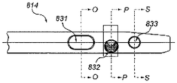
Fig. 55 is a cross-sectional view of the intramedullary nail taken along line O-O of fig. 54.
Fig. 56 is a cross-sectional view of the intramedullary nail taken along line P-P of fig. 54.
Fig. 57 is a cross-sectional view of the intramedullary nail taken along line S-S of fig. 54.
Fig. 58 is a side view of the intramedullary nail of fig. 47-57 including a bend, perpendicular to the AP plane of fig. 50.
Fig. 59 is an end view of the intramedullary nail of fig. 58.
FIG. 60 is a plan view of the lateral side of the nail of FIG. 58.
Detailed Description
Methods, devices, and systems according to embodiments of the present disclosure seek to provide improved treatment for femoral fractures. Fig. 1-6 show various views of one embodiment of an intramedullary nail 100. The intramedullary nail 100 has a longitudinal bore 130 therethrough to facilitate insertion into bone. The intramedullary nail 100 has a proximal portion 102, a transition portion 104, and a distal portion 106.
The proximal portion 102 of the particular structure shown in fig. 1-6 preferably has anatomically suggested shape characteristics that more accurately correspond to typical cortical bone. One version of this shape is shown in the cross-sectional view of proximal portion 102 of fig. 6. The particular cross-section of the proximal portion 102 shown in fig. 6 is generally non-circular and exists at least along some portion of the length of the intramedullary nail 100. The cross-section of fig. 6 has a lateral side or aspect 108 that is larger than a medial side or aspect 109. Lateral side 108 and medial side 109 are joined by a first side 110 and a second side 116. At the intersection of first side 110 and outer side 108 is a first fillet 112, and at the intersection of second side 116 and outer side 108 is a second fillet 114. First side 110, second side 116, and outer side 108 have approximately equal lengths. First side 110 and second side 116 are oriented at an acute angle with respect to lateral side 108 such that medial side 109 is smaller than lateral side 108. By making lateral side 108 larger than medial side 109, the rotational stability of intramedullary nail 100 is increased and resistance to bending and torsion may also be enhanced.
The inner side 109 shown in fig. 6 may be rounded. As can be seen in fig. 4, a rounded medial side 109 protrudes from the transition portion 104 and continues to the proximal end of the intramedullary nail 100. The protrusion of the medial side 109 corresponds to the talar region of the femur and improves the uniformity of load distribution between the bone and the intramedullary nail 100.
In addition, the general cross-sectional geometry of the proximal portion 102 reduces peak stresses in the proximal portion 102. More specifically, a typical failure mode of the combination of an intramedullary nail and a screw assembly is a tension failure of the nail on its outer side. Tension is created by a bending moment caused by the weight load applied to the screw assembly. Thus, it would be beneficial to reduce the stress in the proximal portion of the nail so as to include more material on the sides, i.e., outer sides, of the nail under tension to more effectively shape the cross-section so as to enhance strength and robustness, or both, in the side regions. The design shown in fig. 6 achieves this. Lateral side 108 is wider than medial side 109, thereby imparting, at least in part, a flange-like effect. The stress induced per unit area on lateral side 108 is less than if the lateral side were characterized by a smaller cross-sectional area (e.g., the cross-sectional area of medial side 109).
A structure in accordance with another embodiment of the present disclosure benefiting from the same principles is shown in fig. 1B and 1C, which illustrate an intramedullary nail 1100 having a generally circular cross-section with a generally circular bore 1128 disposed non-concentric with the perimeter of the cross-section. In the particular configuration shown in these two figures, offset holes 1128 are offset toward inner side 1109 so that a greater portion of the material is available to carry loads and reduce stresses on outer side 1108. Similarly, any cross-section that provides more material on the outside of the portion will reduce the stress per unit area on that side in the nail.
Regardless of the particular manner in which material or mass may be added to or removed from certain portions of the outer portion of the cross-section of proximal portion 102, in order to increase the strength and firmness, or both, of the outer portion, the effect may be characterized as imparting a moment of inertia to the cross-section oriented at least partially in the direction of the outer side or aspect 108. In a preferred embodiment, the moment of inertia (shown as being represented by the letter M on fig. 6) may be characterized as extending in a lateral direction, or at least partially toward the lateral aspect or lateral side 108, from a point P, which is the midpoint of a line L, extending from an intersection I1 of the line with a tangent T1 of the lateral aspect 108 to an intersection I2 of the line with a tangent T2 of the medial aspect 109. Stated another way, the effect will, at least in some instances, result in a cross-section characterized by a moment of inertia extending at least partially in an outboard direction from a center of the cross-section. Preferably, the center may be a midpoint between the lateral and medial edges of the cross-section. Alternatively, the center may be the center of mass of the cross-section. The radius of gyration, reflected by the moment of inertia, which is a function of the square of the distance of the incremental mass from the center, reflects the additional strength in the lateral portion of the proximal portion 102, which is caused by more mass or more strategically placed mass in the cross-section. In some configurations, the line L is coplanar with the axis of the longitudinal bore 130, and coplanar with the plane of the cross-section, and thus defined by the intersection of these planes. One as reflected in fig. 1A and the other as reflected in fig. 1B and 1C, and bearing in mind that these are but two of the myriad of structures that may impart additional strength and robustness to such an outer side, the cross-section may be, but need not be, asymmetrical with respect to at least one of its axes. Additionally, the longitudinal bore 130 may be positioned to share its central axis with the geometric center of the cross-section, or it may be offset to help impart lateral strength or for other purposes.
In the particular arrangement shown in fig. 1-6, first side 110, second side 116, and outer side 108 have flat portions. Alternatively, the sides may be curved. In the embodiment shown in fig. 1-6, the medial side 109 is rounded, but one skilled in the art will appreciate that the medial side may be flat, or have one or more flat portions.
The proximal portion 102 has a proximal transverse bore 118 that receives a fastening or screw assembly 200 (various versions of which are shown in fig. 19-41) through the intramedullary nail 100. One embodiment of the proximal transverse bore 118 shown in fig. 1-4 is formed by two overlapping circular bores 120,122, wherein the proximal circular bore 120 is smaller in diameter than the distal circular bore 122. The proximal circular hole 120 is shown with a shoulder 132 for limiting the insertion depth of the screw assembly, as will be explained in more detail below. Those skilled in the art will appreciate that various other holes may be used that allow insertion of various screw assemblies. For example, fig. 33 shows an intramedullary nail with a circular hole. The embodiment of fig. 33 will be described in more detail below. Fig. 45-47 illustrate another non-circular aperture, which will be described in more detail below.
The proximal portion 102 shown in fig. 3 has a proximal aperture 128. The proximal bore 128 is threaded to allow insertion of a set screw, which may be used to fix the rotational and translational position of the screw assembly in the proximal transverse bore 118. The set screw may also include a mechanism for spanning the compression screw 204 (fig. 19) and interfering with the lag screw 202 (fig. 19) to independently limit rotation or translation of the lag screw 202.
As shown in fig. 1-6, the transition portion 104 tapers from the proximal portion 102 to the distal portion 106. The tapered nature of the transition section 104 creates a press fit in the intramedullary canal that controls collapse. The tapered transition portion 104 helps to prevent the nail 100 from being pressed down further into the intramedullary canal of the femur than intended.
In the embodiment of the intramedullary nail 100 shown in fig. 1-6, the transition portion 104 is circular in cross-section, but the cross-section may vary as known to those skilled in the art. The cross-section may be anatomically similar to the cross-section of proximal portion 102, oval or non-circular. In the embodiment shown in fig. 1-6, the transition portion 104 includes a distal transverse bore 124. The distal hole 124 allows insertion of a distal locking screw through the intramedullary nail 100 for locking the intramedullary nail 100.
The distal portion 106 of the intramedullary nail 100 is generally cylindrical and is configured to provide reduced bending stiffness. The embodiment shown in fig. 1-5 has a longitudinal slot 126 through the center of the distal portion 106 that forms two sides 134, 136. The slots reduce the bending stiffness at the distal end of the intramedullary nail 100 and reduce the chance of circumferential fracture of the prosthesis.
Fig. 1D shows an intramedullary nail 100 according to another embodiment of the present disclosure. The nail is characterized by a non-circular cross-section of its proximal portion, which is symmetrical with respect to its lateral-medial axis (in this case, an elliptical cross-section is preferred but not necessary), and by a central longitudinal bore (in this case, a circular cross-section is preferred but not necessary). The nail obtains additional stability to the extent that it can resist twisting in the medullary canal. It also achieves the goal of placing more mass towards the outside edge or aspect of the proximal cross-section. In addition, it places additional mass toward the inboard edge or aspect and thus provides additional structure that acts as a fulcrum to reduce the mechanical advantage of the fastener assembly, which is the member that applies tensile stress to the outboard edge or aspect when loaded.
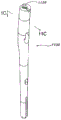
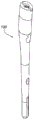
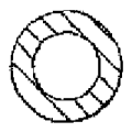
Fig. 7-18 show an intramedullary nail 100 according to other embodiments of the present disclosure. Fig. 7 and 13 show the intramedullary nail 100 without a through longitudinal bore.
Fig. 8 and 14 show an intramedullary nail 100 having reduced stiffness slots 140 in the transition portion 104 and the distal portion 106. The stiffness reducing slots 140 reduce the bending stiffness at the distal end of the intramedullary nail 100 and may be used to receive locking screws in some embodiments.
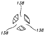
Fig. 9 and 15 show the intramedullary nail 100 having three longitudinal grooves 138 forming a cloverleaf pattern in the distal portion 106 and a portion of the transition portion 104. Such a pattern more readily allows blood flow near the intramedullary nail 100 and also reduces bending stiffness at the distal end of the nail 100.
Fig. 10 and 16 show the intramedullary nail 100 with a series of longitudinal grooves 146 in a portion of the distal portion 106 and the transition portion 104. The longitudinal grooves 146 reduce bending stiffness at the distal end, provide rotational resistance, and enhance blood flow near the intramedullary nail 100.
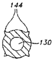
Fig. 11 and 17 show the intramedullary nail 100 in which the transition portion 104 and the distal portion 106 have fins 144. The fins 144 provide rotational resistance to the intramedullary nail 100.
Fig. 12 and 18 show an intramedullary nail 100 having barbs 142 positioned in a portion of the distal portion 106 and the transition portion 104. Barbs 142 provide rotational resistance to intramedullary nail 100.
Intramedullary nails according to the present disclosure may be inserted into a patient by any suitable known technique. Typically, the intramedullary canal of the bone will be prepared with a suitable tool to create a void for insertion of the nail. Some portion of the void may be prepared about 1 millimeter larger than the perimeter of the spike to allow sufficient space for blood flow after insertion of the spike. Optionally, a guide pin or guide wire is inserted into the prepared medullary canal. The nail is then introduced into the desired position. If the staple is cannulated, the staple may be guided over a guide wire. The position of the pin can be confirmed by image enhancement techniques.
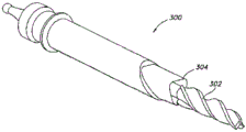
Fig. 19 shows one embodiment of a tool 300 for preparing a medullary canal. The tool has a drill bit 302 for reaming and also has a mortise 304. In operation, the drill bit 302 reams the medullary canal of the femur and the mortice 304 cuts a larger portion of the more proximal end of the bone. As shown in fig. 19, the mortise chisel 304 has an anatomically derived cross-section that is substantially the same shape as the proximal region of the intramedullary nail. By applying this type of shaped mortice, it will be better to enable the proximal end of the nail to sit on cortical bone that has undergone only minimal changes. The tongue 304 may have a wide variety of shapes, even complex asymmetric shapes. This is advantageous because it can accept a wide variety of intramedullary nail shapes using the device and method for preparing a void, rather than merely over reaming a circular void. The provision of a precisely conforming void is valuable to avoid unnecessary removal of healthy bone and to ensure stable seating of the nail.
During operation, the tool 300 is advanced as a unit, wherein reaming of the drill bit 302 and cutting of the mortise 304 are simultaneous. The drill 302 may be rotated using a powered driver or by hand. Similarly, the entire tool 300 may be advanced into the medullary canal manually, or by mechanical advantage or powered device. In other configurations, the drill bit 302 may be fitted with a cannula (not shown) so that the entire tool 300 may be operated over and guided by a guide wire that has been inserted into the medullary canal.
In other embodiments, the drill bit used for reaming is a more conventional reamer that is separate from the cutting tool, such as the mortise 304. The method for preparing the void in this case would include first reaming out the opening with a conventional reamer. The void will then be prepared using a device, such as a chisel or broach, shaped similar to the intramedullary nail to be implanted. The chisel or broach may be driven by hand with a hammer or mallet, or by other power means. A nail corresponding to the prepared void will then be implanted.
Other custom instruments such as profiled broach or custom router bits and templates may also be used. Broaches have long been used to prepare the opening of a hip stem and the use of broaches will be well known to those skilled in the art. The router bit and template may be effectively used to mill out a desired shape in bone. This method may also be used in conjunction with reaming or broaching to create the desired void.
The intramedullary nail of the present disclosure may be used to treat proximal femoral fractures and femoral shaft fractures (in addition to other long bone fractures). When used to treat femoral shaft fractures, intramedullary nails are secured in the femur by one or more fastening devices. When used to treat a proximal femoral fracture, the intramedullary nail is preferably used in conjunction with a proximal fastening assembly.
Fig. 20 and 21 show the intramedullary nail 100 used in combination with the fastening assembly 200. This type of fastener assembly can be used in a variety of other bones and for treating many other conditions, but for purposes of providing examples it is described herein as being used with a proximal femur. In general, the fastening assembly 200 is useful in any situation in which one section of bone will be pulled back toward or pushed away from another section of bone in a controlled manner. The fastening assembly provides such additional advantages: which may be arranged to allow the assembly to slide in a desired direction after movement of the bone segments has been completed.
As shown in fig. 21, the axis of the proximal transverse hole 118 in the intramedullary nail 100 is angled relative to the proximal portion 102 and is oriented toward the femoral head during use. In this embodiment of the fastening assembly 200, an engagement member such as a lag screw 202 is used in conjunction with a compression device such as a compression screw 204 or compression peg. The screws are arranged such that, in use, the perimeter of the lag screw 202 partially intersects the perimeter of the compression screw 204 such that the compression screw 204 partially nests within the perimeter of the lag screw 202. This particular combination of lag screw 202 and compression screw 204 is further illustrated in fig. 22-32. Briefly, the lag screw 202 shown in these figures is intended to engage the femoral head and slide within the transverse bore 118 of the nail 100. The compression screw 204 engages the shoulder 132 or other structure of the nail 100 in the transverse bore 118 and is also threaded into a portion of the lag screw 202 in which the compression screw 204 nests such that rotation of the compression screw 204 controls sliding of the lag screw 202 relative to the nail 100 and thus compression of the femoral head against the fracture site.
The lag screw 202 shown in these figures includes an elongated body 206 and a threaded end 208. As shown in fig. 24 and 25, the threaded end 208 does not include a sharp tip, which reduces the likelihood of cutting through the femoral head. The elongated body 206 includes a channel 212 that allows the compression screw 204 to be positioned partially inside the perimeter of the lag screw 202. The channel 212 includes a threaded portion 210 that is complementary to and cooperates with a threaded portion 214 of the compression screw 204. Compression screw 204 includes a threaded portion 214 and a head portion 215. The threaded portion 214 of the compression screw 204 is configured so that the threads are relatively flat and smooth at the outer surface so that it can easily slide in the hole and also reduces the likelihood of cutting out.
The compression screw 204 may also be received in a pre-drilled hole in the femoral head through the proximal transverse bore 118. The threaded portion 214 of the compression screw 204 engages the threaded portion of the channel 212 of the lag screw 202. The proximal transverse bore 118 includes an internal shoulder 132 (fig. 21) to limit the sliding movement of the compression screw 204 in a generally medial direction and thereby limit the sliding movement of the lag screw 202 through the bore 118. When the compression screw 204 is tightened, the compression screw threads 214 engage the lag screw channel threaded portion 210 and the compression screw 204 moves along the lag screw 202 in a generally medial direction. The head portion 215 of the compression screw 204 engages the shoulder 132 of the proximal transverse bore 118 to prevent further movement of the compression screw 204 in a generally medial direction. When the compression screw 204 is tightened, the lag screw 202 is pulled in a generally lateral direction toward the intramedullary nail, thereby providing compression to the fracture. The compression screw 204, which partially intersects the perimeter of the lag screw 202, provides greater surface resistance and helps prevent rotation of the femoral head. The compression screw 204 thus not only serves as part of the mechanism for moving the segments of fractured bone relative to one another, but also is in direct contact with the bone of the femoral head, thereby helping to prevent rotation of the femoral head about the axis of the lag screw 202.
In one embodiment, a set screw (not shown) positioned in the proximal bore 128 of the intramedullary nail is used to engage the compression screw 204 and secure the compression screw 204 and the lag screw 202 in place. The use of a set screw to secure the fastening assembly 200 in place depends on the type of fracture. If a set screw is not used to engage the fastener assembly, the fastener assembly 200 can slide in the proximal bore, which is limited by the shoulder 132.
In the lag and compression screw embodiments shown in fig. 20-32, the diameter of the compression screw 204 is smaller than the diameter of the lag screw 202. The diameters of the lag screw 202 and compression screw 204 may be the same, or the lag screw 202 may have a smaller diameter than the compression screw 204. The threads of the lag screw 202 and compression screw 204 may be of various different shapes known to those skilled in the art. Generally, the purpose of the lag screw 202 is to obtain a grip in the bone, and the purpose of the compression screw 204 is to engage and pull or move the lag screw. Any configuration that allows these functions is within the scope of the present disclosure.
The fastening assembly 200 may additionally be provided to allow for the addition of a prosthetic femoral head and neck. In such an embodiment, the lag screw 202 would be replaced by a prosthetic head and neck. The neck will fit into the proximal transverse bore 118 in the nail 100. This design would be beneficial in cases where a repaired femoral fracture and deterioration or re-injury of the hip joint must be followed by Total Hip Arthroplasty (THA). The determination of the completion of THA may be made intraoperatively or after a certain period of time. Rather than having to prepare the femur to accept the hip stem as is known with THA, only a small portion of the bone will need to be removed along with the fastening assembly 200. The prosthetic head and neck may then be inserted into the proximal transverse bore 118, preparing the acetabulum, and completing the remainder of the THA.
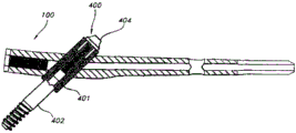
Fig. 33 is a cross-sectional view of an intramedullary nail 100 having an alternative fastening assembly 400 according to another embodiment of the present disclosure. The illustrated fastening assembly 400 is very similar to Smith, which is more fully disclosed in U.S. Pat. No.5,032,125 and various related International patents&IMHS of Nephew corporation®The compression fastening assembly of the system, which is hereby incorporated by reference. The improvement of the illustrated device is that it includes an intramedullary nail 100 having the anatomically derived shape discussed above and its many advantages. During operation, the sleeve 401 fits through the intramedullary nail 100 and may be secured to the nail by a set screw or other effective mechanism. The sliding lag screw 402 is axially movable in the sleeve 401. The compression screw 404 is threaded into the sliding lag screw 402 such that tightening of the compression screw 404 draws the sliding lag screw 402 back into the bushing 401. With this mechanism, the bone segments can be brought into the desired position, but once positioned still allow for sliding compression.
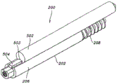
Fig. 34-35 show a fastening assembly 200 having a lag screw 202 and a compression peg 502 according to another embodiment of the present disclosure. As shown in fig. 34, the lag screw 202 and compression peg 502 are arranged such that, in use, the perimeter of the lag screw 202 partially intersects the perimeter of the compression peg 502, although in some embodiments, the perimeters may be adjacent rather than intersecting. The lag screw 202 includes an elongated body 206 and a threaded end 208. The lag screw 202 has a key 504 located on the channel 212. The compression bolt 502 has a slot 503 adapted to receive a key 504 of the lag screw 202. The key 504 and slot 503 may be of various complementary shapes when considered in cross-section, such as triangular, D-shaped, key-hole, and other shapes apparent to those skilled in the art. During operation, the compression bolt 502 may be moved relative to the lag screw 202 by a compression tool (not shown) that applies different forces between the compression bolt 502 and the lag screw 202, or between the entire assembly and the intramedullary nail 100.
In the fastening assembly 200 shown in fig. 34-35, the lag screw 202 is received for sliding in the proximal bore of the intramedullary nail such that the lag screw 202 extends across the break and into the femoral head. The threaded end 208 of the lag screw 202 engages the femoral head. Once the lag screw 200 has been properly engaged with the femoral head, the compression peg 502 is inserted into the proximal bore to enter the predrilled bore of the femoral head to prevent further rotation of the lag screw 202 when the slot 503 of the compression peg 502 receives the key 504 of the lag screw 202. The compression peg 502 helps prevent rotation of the femoral head on the lag screw 202 by providing more area for resistance. The compression peg 502 is fixed in place in the intramedullary nail 100 by a set screw positioned in the proximal bore of the nail. The lag screw 202 may slide over a compression peg 502 that passes through the proximal bore. In another embodiment, the compression peg 502 has barbs on its surface.
A fastening assembly 200 according to another embodiment of the present disclosure is shown in fig. 36-37 and has a compression peg 502 and a lag screw 202 similar to the embodiment shown in fig. 34-35, except that a key 504 of the lag screw 202 and a slot 503 of the compression peg 502 have complementary ratchet teeth 506. The compression peg 502 is fixed in place in the intramedullary nail by a set screw positioned in the proximal bore. Compression of the fracture may be achieved by tightening the lag screw in a generally lateral direction. The ratchet 506 allows the lag screw 202 to move in a generally lateral direction, but prevents the lag screw 202 from moving in a generally medial direction. A compression tool similar to that described with respect to fig. 34-35 may be used to accomplish this movement.
Fig. 38-39 show a fastening assembly 200 having a lag screw 602, a cross-wire screw 610, and a compression screw 604. The lag screw 602 includes an elongated body 606 and a threaded end 608. The elongated body 606 is semi-circular in cross-section. The screw 602,604,610 is positioned such that the perimeter of the lag screw 602 intersects the perimeter of the cross-hair screw 610 and the compression screw 604. The elongated body 606 of the lag screw 602 is threaded to complement and cooperate with the threaded portion of the cross-wire screw 610. The cross-wire screw 610 is threaded to engage the lag screw 602 and the compression screw 604. Compression screw 604 includes a threaded portion 614 and a head portion 612.
In the embodiment of fig. 38-39, lag screw 602, cross-wire screw 610, and compression screw 604 are simultaneously received for sliding in the proximal bore of the intramedullary nail. Lag screw 602 extends across the break and into the femoral head. The threaded end 608 of the lag screw 602 engages the femoral head. When the compression screw 604 is tightened, the compression screw threads 614 engage the threads of the cross-wire screw 610 and the lag screw 602, thereby moving the lag screw 602 in a generally lateral direction toward the intramedullary nail to provide compression of the femoral head. The cross-wire screw 610 is then rotated, causing the compression screw 604 to move in a distal direction away from the lag screw 602. The fastening assembly 200 may alternatively be configured such that the compression screw 604 moves proximally relative to the lag screw 602. The compression screw 604, which is separate from the lag screw 602, helps prevent rotation of the femoral head on the lag screw 602 by increasing the area for resistance.
Fig. 40-41 show the fastening assembly 200 with a lag screw 702 and a compression peg 704. Lag screw 702 includes an elongated body 706 and a threaded end 708. The elongated body 706 is semi-circular to allow the compression bolt 704 to be positioned partially inside the perimeter of the lag screw 702 for insertion into the femur, and has a key 712 positioned on the medial side of the elongated body 706. The elongated body 706 also has a bore 710 therethrough. The compression peg 704 is generally cylindrical and is sized to fit within the semi-circular body 706 of the lag screw. The tension screw key 712 is received in the compression peg 704 through a slot 714. The key 712 and slot 714 contain complementary ratchet teeth.
The lag screw 702 and compression bolt 704 are simultaneously received for sliding in the proximal bore of the intramedullary nail and into the predrilled bore of the femur. Lag screw 702 extends across the break and into the femoral head. The threaded end of the lag screw 702 engages the femoral head. A compression tool similar to that described with respect to fig. 34-35 may be used to accomplish movement between the compression peg 704 and the lag screw 702 or between the entire assembly and the intramedullary nail 100. The set screw may be used to fix the position of the fastening assembly. The set screw is configured such that when the set screw is tightened, a protrusion on the set screw is received through the slot 710 of the lag screw 702 and moves the compression screw 704 away from the lag screw 702. The compression screw 704, which is separate from the lag screw 702, helps prevent rotation of the femoral head on the lag screw by increasing the area for more resistance.
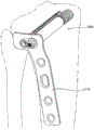
Fig. 42 shows another embodiment in which a fastening assembly 200 is employed in cooperation with the compression plate 150. As shown, the device is being applied to the femur. The various embodiments of the fastening assembly 200 disclosed above may be used with similar compression plates, and various compression plates may be provided that may be adapted for use with other anatomical portions. For example, FIG. 43 shows another embodiment in which the fastening assembly 200 is used with the periarticular plate 170. The plate and fastening assembly shown is being applied to the proximal tibia.
Fig. 44 shows another embodiment in which a fastener assembly 200 is used in conjunction with a humeral nail 190. As shown, the head portion 212 of the compression screw 204 bears against the humerus to induce compression of the humerus. The bone segment may be pulled into position for proper treatment using a compressive force applied to the lag screw 202 and the lag screw 202 secured to the bone segment by its threaded end 208. In some cases, it may be advantageous to place a washer or bearing surface (not shown) between the head portion 212 and the humerus against which the head portion 212 is pressed. In yet another variation, the opening in the humerus can be enlarged, allowing the head portion 212 to penetrate the humerus and rest on a portion of the humeral nail 190. In such an embodiment, the fastening assembly 200 would be shorter than shown in FIG. 45 to obtain purchase with the threaded end 208 in the same bone region.
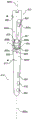
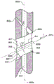
Referring to fig. 45-47, a universal femoral nail 800 defines a reconstruction aperture 801 for treating and targeting a fracture or other injury of the femoral head and neck in a reconstruction mode as described above, and an antegrade aperture 802 for treating a fracture of the femoral shaft in an antegrade mode and targeting the lesser tuberosity. The nail 800 includes a central long axis 800a, a head 800b, and a shaft 813, the head 800b being formed on a proximal portion 812 of the nail 800, and the shaft 813 extending from the head 800b to a distal portion 814 of the nail 800. The cross-sectional shape of the head 800b, in a plane perpendicular to the long axis 800a, is generally non-circular. As shown in fig. 50, the cross-sectional shape of the head 800b is generally trapezoidal and includes a rounded portion. For example, at least a portion of outer side 800d is flat. However, inner side 800e is generally circular. As also shown in fig. 50, the medial-lateral plane M-L bisects the head 800b, including the central through axis 801a of the reconstruction aperture, and including the central long axis 800a of the peg 800. Thus, as shown, the medial-lateral plane M-L is coplanar with the coronal plane of the nail 800, which separates the front face of the nail from the back face of the nail. It should be noted that this plane does not necessarily relate to the coronal plane of the patient's body or even the coronal plane of the patient's femur. Additionally, in some embodiments, the reconstruction aperture 801 is not centrally disposed in the head 800b such that the medial-lateral plane M-L does not include the central through axis 801a, but the medial-lateral plane M-L is parallel to the central through axis 801a of the reconstruction aperture 801 and to the coronal plane of the nail 800.
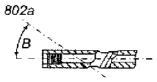
The reconstitution transverse holes 801 are "light bulb" shaped and oriented offset from the long axis 800a of the nail 800 and are configured to receive tension members (lag members) and compression members, such as the tension screws 202 and compression screws 204 described above. To target the femoral head and neck in the reconstruction mode, the central through axis 801a of the reconstruction bore 801 lies in the medial-lateral plane M-L and is oriented at an angle a of about 122 degrees relative to the central long axis 800 a. The antegrade transverse bore 802 is also oriented at an angle B of about 35 degrees from the long axis 800 a. The antegrade aperture 802 is oriented such that a central through axis 802a of the antegrade aperture 802 lies in the antegrade plane AP, which is parallel to the long axis 800a and is radially offset from the medial-lateral plane M-L by an angle C of about 12 degrees. As shown in fig. 50, the antegrade hole 802 is not centered in the head 800b such that a central through axis 802a of the antegrade hole 802 does not intersect the long axis 800a of the nail 800. In certain embodiments, as shown in FIG. 50, central through axis 802a intersects medial-lateral plane M-L near medial side 800 e.
As shown in fig. 48 and 49, the staple 800 further includes three holes 831,832 and 833 positioned in the distal portion 814 of the staple that can receive pins or screws to stabilize the distal portion of the staple 800 during use. The proximal-most aperture 831 is formed as a slot, and the central aperture 832 and the distal-most aperture 833 are formed as circular apertures. When treating fractures of the femoral shaft, as discussed above, a bone pin or other fastener (not shown) may be disposed in one or more of the three holes 831,832 and 833 and secured to healthy bone.
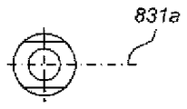
The most proximal and distal holes 831 and 833 are formed such that the respective central through axes 831a and 833a of the most proximal and distal holes 831 and 833 lie in a plane parallel to the antegrade plane AP. In other words, central through- axes 831a and 833a are radially offset from medial-lateral plane M-L by the same angle (offset) as central through-axis 802c of antegrade aperture 802. Thus, it can be said that the antegrade, most proximal and most distal holes 802, 831, 833 are parallel, or lie in parallel planes-even though they may be oriented differently with respect to the central axis 800a of the nail 800. For example, as discussed above, the central through axis 802a of the antegrade aperture 802 is oriented at an angle of 35 degrees relative to the central long axis 800a of the nail 800. However, the proximal-most and distal-most apertures 831 and 833 can be formed to be oriented at approximately 90 degrees or other angles with respect to the central long axis 800 a. In some embodiments, the central through axis 831a of the most proximal bore 831 lies in the same plane as the central through axis 833a of the most distal bore 833. Additionally, central through axes 831a and 833a of proximal-most and distal-most apertures 831 and 833 may lie in the antegrade plane AP, such that central through axes 802a, 831a and 833a are coplanar.
The central through axis 832a of the central aperture 832 is also radially offset from the medial-lateral plane M-L. However, central through axis 832a is offset from medial-lateral plane M-L by a different amount than central through axes 831a and 833 a. For example, the central through axis 832a of the central aperture 832 is offset 37 degrees from the medial-lateral plane M-L and is offset 25 degrees in a radial direction from the antegrade plane AP.
When treating fractures of the neck, head and intertrochanteric region of the femur, the nail 800 may be used in conjunction with first and second components, such as a lag screw 202 and a compression screw 204, received in the reconstruction bore 801. When treating only fractures in the femoral shaft, the nail 800 would be used in conjunction with a bone pin received in the antegrade hole 802. Extending along the long axis 800a of the nail 800 is a bore 816. Set screws (not shown) may be disposed in the bores 816 for locking the first and second components or bone pins.
The reconstitution hole 801 has a first semi-cylindrical hole 810 associated with a first portion 811 (FIG. 46) of the reconstitution hole 801 and a second U-shaped hole 820 associated with a second portion 821 (FIG. 46) of the reconstitution hole 801. The nail 800 includes an inner wall 805 (fig. 47) that defines a reconstitution aperture 801. The inner wall 805 includes a first semi-cylindrical portion 807 that defines a semi-cylindrical bore 810, and a second U-shaped portion 809 that defines a U-shaped bore 820. As shown, the reconstruction aperture 801 has a constant cross-sectional shape along the length dimension L of the reconstruction aperture 801, except for the shoulder 803. Shoulder 803 is defined by an outward step 818 in U-shaped portion 809.
The U-shaped portion 809 of the inner wall 805 includes a semi-cylindrical arc 809a opposite a face 841 of the semi-cylindrical portion 807 and two opposing walls 809b and 809c extending from the semi-cylindrical arc 809a opposite each other. The U-shaped portion 809 of the inner wall 805 also includes a face 845 defined by a plane between the edges 809e and 809f of the walls 809b and 809 c. As shown, the face 845 of the U-shaped portion 809 is coplanar with the face 841 of the semi-cylindrical portion 807. Semi-cylindrical arc segment 809a includes a face 843 that opposes face 841 of semi-cylindrical portion 807 of inner wall 805 (and face 845 of U-shaped portion 809 of inner wall 805) and is spaced apart by opposing walls 809b and 809 c.
In certain embodiments, the face 843 of the semi-cylindrical arc 809a is spaced a distance D from the first open face 841 of the first semi-cylindrical bore 810 such that, when disposed in and abutting the semi-cylindrical arc 809a, a cylindrical member having a circular cross-section (which has a diameter substantially the same as the diameter of the semi-cylindrical arc 809 a) extends into the first portion 811 of the reconstruction bore 801. For example, where the semi-cylindrical arc 809a is a 180 degree arc, the parallel walls 809b and 809c extend from the semi-cylindrical arc 809a (that is, from the face 843 of the semi-cylindrical arc 809 a) a distance D that is less than the radius of the semi-cylindrical arc 809 a. In certain embodiments, the semi-cylindrical arc 809a is between about 5 millimeters and about 15 millimeters in diameter and the amount of overlap of such a cylindrical component with the cylindrical component received in semi-cylindrical portion 807 is between about 1 millimeter and 5 millimeters.
As shown, the opposing walls 809b and 809c are parallel, and the semi-cylindrical arc 809a is a 180 degree arc. Alternatively, however, the opposing walls 809b and 809c can be diverging and/or the semi-cylindrical arc 809a can be an arc of less than 180 degrees. Thus, when a part sized to fit in the semi-cylindrical arc 809a is disposed in the U-shaped hole 820, the part is not constrained by the narrowing of the U-shaped hole 820. Thus, a component sized to fit within semi-cylindrical arc 809a is constrained from moving into semi-cylindrical hole 810 only when a second component is disposed within semi-cylindrical hole 810. For example, when compression screw 204 is disposed in U-shaped portion 809 of inner wall 805 and lag screw 202 is disposed in semi-cylindrical portion 807 of inner wall 805, compression screw 204 is constrained to remain in U-shaped portion 809 and lag screw 202 and compression screw 204 cooperate to resist a moment applied to one or both of lag screw 202 and compression screw 204. However, if lag screw 202 is not present in semi-cylindrical portion 807 of inner wall 805, compression screw 204 may move in response to forces exerted on compression screw 204 such that the occurrence of bending or fracture of compression screw 204 is reduced.
With additional reference to fig. 48-52, the antegrade aperture 802 includes a first opening (or entry) 802a formed in the lateral side 800d of the nail 800 proximate to a first opening (or entry) 801a of the reconstitution aperture 801 formed on the lateral side 800d of the nail 800. The first opening 801a of the reconstitution hole 801 is generally centered on the lateral side 800d of the nail 800, and the first opening 802a of the antegrade hole 802 is not centered on the lateral side 800d of the nail 800. The non-circular cross-sectional shape of head 800b having lateral side 800d that is larger than medial side 800e provides additional surface area for eccentrically positioning first opening 802a of antegrade hole 802 in head 800b and may provide increased strength as compared to a head having a circular cross-sectional shape when antegrade hole 802 is oriented offset from medial-lateral plane M-L.
In addition, while the reconstruction bore 801 is oriented in the direction of the femoral neck such that the second opening (or outlet) 801b of the reconstruction bore 801 formed in the medial side 800e of the nail 800 is proximate to the first opening 801a of the reconstruction bore 801, the antegrade bore 802 is oriented distally toward the second opening (or outlet) 802b formed in the inner wall 805 at a location proximate to the second opening 801b of the reconstruction bore 801, which second opening 801b of the reconstruction bore 801 is formed in the medial side 800e forming the nail 800. However, in certain embodiments, the second opening 802b of the antegrade aperture 802 may be formed in the medial side 800e of the staple 800, and the second opening 802b may be positioned proximal or distal to the second opening 801b of the reconstitution aperture 801.
As shown in fig. 51 and 52, outlet opening 802b is formed on the inner side surface 800e of spike 800 such that outlet opening 802b is fully contained within outlet opening 801b of reconstitution hole 801. For a given size of antegrade and reconstitution holes 802 and 801, the co-location of outlet openings 802b and 801b reduces the amount of material removed from the inner side 800e of the nail 800. As mentioned above, the non-circular cross-sectional shape of head 800b, in combination with the radial offset of the antegrade plane AP from the medial-lateral plane M-L, allows for co-location of outlet openings 802b and 801b while maintaining the structural strength of head 800 b.
In some embodiments, as shown in fig. 58 and 59, the head 800b of the nail 800 is angled at an angle D (e.g., 5 degrees) relative to the shaft 813. A bend is formed in the antegrade plane AP such that a tangent to the long axis 800a at a location 831 in the head 800b makes an angle of about 5 degrees with respect to a tangent to the long axis 800a at a location 833 in the shaft 813. As shown, both the head 800b and the shaft 813 are generally straight in the antegrade plane AP. As shown in fig. 59 and 60, the peg 800 is curved, perpendicular to the antegrade plane AP, such that the antegrade plane AP is also curved. The curves shown in fig. 60 are compound, having more than one radius of curvature perpendicular to the antegrade plane AP.
Those skilled in the art will appreciate that the specific embodiments described above and illustrated in the drawings are provided for purposes of illustration and that various modifications may be made in the structure and materials of the illustrated embodiments. For example, while the non-circular apertures of fig. 45-47 are shown as having semi-cylindrical portions that are circular, the non-circular apertures may have semi-cylindrical portions with other cross-sectional shapes (e.g., elliptical or rectangular). Thus, fastening members having a corresponding shape, i.e., cylindrical fasteners having a square, rectangular, oval, crescent, or other cross-sectional shape, may be used. Further, the non-circular hole may have additional portions, which may or may not be cylindrical. Additionally, one or more of the apertures 831,832,833 positioned near the distal end 800c may be angled in a manner other than perpendicular to the axis 800a, with the first opening positioned proximal or distal to its second opening. Further, in general, the cross-sectional shape of the shaft 813 in a plane perpendicular to the long axis 800a is substantially circular, but the diameter of the shaft 813 may vary along the long axis 800 a. For example, all or a portion of the shaft 813 may be tapered. In addition, the head 800b may be formed in other cross-sectional shapes including, for example, circular, oval, or polygonal. However, with other shapes selected for the head 800b, the medial-lateral plane M-L still includes the central long axis 800a and is parallel to or includes the central through axis 801a of the reconstitution hole 801. Additionally, the transverse bore 801 may be oriented such that the angle a may be about 110 degrees to about 150 degrees, or about 120 degrees to about 130 degrees. The central through axis 832a of the central aperture 832 may be offset from the medial-lateral plane M-L and the forward plane AP by other amounts, such as by an angle of about 20 to about 75 degrees, or about 30 to about 60 degrees. Angle C may be about 0 degrees to about 30 degrees, about 0 degrees to about 20 degrees, or about 10 degrees to about 15 degrees. Angle D may be about 0 degrees to about 20 degrees, or about 0 degrees to about 10 degrees. The central through axis 832a of the central aperture 832 may be radially offset from the antegrade plane by an angle of about 0 degrees to about 90 degrees, or about 0 degrees to about 45 degrees.
Claims (7)
1. An orthopaedic implant comprising:
a nail having a long axis, an inner wall defining a through-hole oriented offset from the long axis, and a first transverse hole proximate the through-hole, the inner wall comprising:
a first semi-cylindrical portion having an arc of more than 180 degrees and defining a first portion of the through-hole, and
a second U-shaped portion having a pair of parallel walls and a semi-cylindrical section having an arc of about 180 degrees, the second U-shaped portion defining a second portion of the through-hole;
the arc of the first semi-cylindrical portion defines a first open face of a first portion of the through-hole and the parallel walls of the second U-shaped portion define a second open face of a second portion of the through-hole opposite the first open face such that a cylindrical component having a diameter substantially the same as the diameter of the semi-cylindrical section of the second U-shaped portion can pass out of the second portion of the through-hole toward the first portion of the through-hole; and is
Wherein the outlet opening of the first transverse bore is formed on the inner side of the nail such that it is completely contained in the outlet opening of the through hole.
2. The orthopaedic implant of claim 1, wherein the exit opening of the first transverse hole is positioned in the inner wall.
3. The orthopaedic implant of claim 1, wherein the first transverse hole extends along an axis that is radially offset with respect to the orientation of the through-hole.
4. The orthopaedic implant of claim 1, wherein the peg further comprises a second transverse hole positioned near a distal end of the peg.
5. The orthopaedic implant of claim 4, wherein the second transverse hole extends along an axis that is non-perpendicular to the long axis of the nail.
6. The orthopaedic implant of claim 1, wherein the first transverse hole is oriented offset from the long axis and has an entrance positioned in a head of the nail, the head of the nail being angled relative to the long axis of the nail.
7. The orthopaedic implant of claim 1, further comprising a second transverse hole positioned near the distal end of the peg, the second transverse hole having an opening aligned with the entrance of the first transverse hole.
Applications Claiming Priority (3)
| Application Number | Priority Date | Filing Date | Title |
|---|---|---|---|
| US22207809P | 2009-06-30 | 2009-06-30 | |
| US61/222078 | 2009-06-30 | ||
| CN201080030243.XA CN102639074B (en) | 2009-06-30 | 2010-06-30 | Orthopedic implants and fastening components |
Related Parent Applications (1)
| Application Number | Title | Priority Date | Filing Date |
|---|---|---|---|
| CN201080030243.XA Division CN102639074B (en) | 2009-06-30 | 2010-06-30 | Orthopedic implants and fastening components |
Publications (2)
| Publication Number | Publication Date |
|---|---|
| CN105726112A CN105726112A (en) | 2016-07-06 |
| CN105726112B true CN105726112B (en) | 2021-04-27 |
Family
ID=43411728
Family Applications (2)
| Application Number | Title | Priority Date | Filing Date |
|---|---|---|---|
| CN201610086929.XA Active CN105726112B (en) | 2009-06-30 | 2010-06-30 | Orthopaedic implant and fastening assembly |
| CN201080030243.XA Active CN102639074B (en) | 2009-06-30 | 2010-06-30 | Orthopedic implants and fastening components |
Family Applications After (1)
| Application Number | Title | Priority Date | Filing Date |
|---|---|---|---|
| CN201080030243.XA Active CN102639074B (en) | 2009-06-30 | 2010-06-30 | Orthopedic implants and fastening components |
Country Status (10)
| Country | Link |
|---|---|
| US (1) | US8834469B2 (en) |
| EP (1) | EP2448505B1 (en) |
| JP (2) | JP5801297B2 (en) |
| KR (1) | KR101743051B1 (en) |
| CN (2) | CN105726112B (en) |
| AU (2) | AU2010266297B2 (en) |
| BR (1) | BRPI1011556A2 (en) |
| CA (1) | CA2765376C (en) |
| RU (1) | RU2580978C2 (en) |
| WO (1) | WO2011002903A2 (en) |
Families Citing this family (65)
| Publication number | Priority date | Publication date | Assignee | Title |
|---|---|---|---|---|
| EP2214572B1 (en) | 2007-11-26 | 2013-09-25 | Biedermann Motech GmbH & Co. KG | Bone nail for the heel |
| WO2009136386A2 (en) | 2008-05-07 | 2009-11-12 | Tornier | Surgical technique and apparatus for proximal humeral fracture repair |
| CN102686177B (en) * | 2009-11-10 | 2015-11-25 | 史密夫和内修有限公司 | Control bone compression |
| US10588647B2 (en) | 2010-03-01 | 2020-03-17 | Stryker European Holdings I, Llc | Computer assisted surgery system |
| WO2012112495A1 (en) * | 2011-02-14 | 2012-08-23 | Synthes Usa, Llc | Intramedullary nail having self-retaining compression slot |
| US9265541B2 (en) | 2011-10-28 | 2016-02-23 | Stryker Trauma Gmbh | Intramedullary nail locking hole arrangement |
| ES2527240T3 (en) * | 2011-10-28 | 2015-01-21 | Stryker Trauma Gmbh | Locking hole arrangement |
| EP2785283B1 (en) * | 2011-11-30 | 2021-01-13 | Smith&Nephew, Inc. | Orthopaedic implant with dynamic trans-fixation slot |
| USD693470S1 (en) * | 2012-04-13 | 2013-11-12 | Lance Fagan | Nail for bone fracture fixation |
| US9427266B2 (en) * | 2012-04-16 | 2016-08-30 | DePuy Synthes Products, Inc. | Bump cut on hole edge |
| DE202012103384U1 (en) * | 2012-09-05 | 2012-09-24 | Signus Medizintechnik Gmbh | Pelvic ring implant |
| WO2014048447A1 (en) | 2012-09-27 | 2014-04-03 | Stryker Trauma Gmbh | Rotational position determination |
| EP2732783B1 (en) | 2012-11-14 | 2016-04-27 | Biedermann Technologies GmbH & Co. KG | Bone nail for the heel |
| USD693929S1 (en) * | 2012-12-13 | 2013-11-19 | Orthopedic Designs North American, Inc. | Intramedullary tang actuator |
| DE102013005414A1 (en) * | 2013-03-28 | 2014-10-02 | Dietmar Wolter | Osteosynthesis system for the multidirectional, angularly stable treatment of fractures of long bones including an intramedullary nail and bone screws |
| CN103654933A (en) * | 2013-12-27 | 2014-03-26 | 杨鹏 | Acetabular anterior wall anatomical steel plate |
| US9839454B2 (en) * | 2014-03-21 | 2017-12-12 | Biomet C.V. | Intramedullary device with compound fastener trajectories |
| JP6562595B2 (en) * | 2014-05-21 | 2019-08-21 | ディトマール・ヴォルター | Osteosynthesis system for multi-directional, angle-stable treatment of tubular fractures with intramedullary nails and bone screws |
| US10398482B2 (en) | 2014-11-25 | 2019-09-03 | Swemac Innovation Ab | Intramedullary nail |
| US20220151664A1 (en) * | 2015-04-16 | 2022-05-19 | Texas Tech University System | Ankle (Tibio-Talar) Fusion Nail |
| CA2983664C (en) | 2015-04-24 | 2023-09-19 | Scott Van Dyke | Humeral nail |
| KR101722252B1 (en) * | 2016-03-18 | 2017-04-03 | 이동훈 | Intramedullary nail having an anti-tilting fuction |
| WO2017188261A1 (en) * | 2016-04-25 | 2017-11-02 | 山田 郁史 | Internal fixator for bone fracture |
| JP6204638B1 (en) * | 2016-04-25 | 2017-09-27 | 山田 郁史 | Fracture fixation device |
| WO2018042595A1 (en) * | 2016-09-01 | 2018-03-08 | 株式会社オーミック | Thighbone fixing tool |
| US10682168B2 (en) | 2016-09-15 | 2020-06-16 | Wright Medical Technology, Inc. | Intramedullary implant with proximal plate and method for its use |
| US10492803B2 (en) | 2016-09-22 | 2019-12-03 | Globus Medical, Inc. | Systems and methods for intramedullary nail implantation |
| US11083503B2 (en) | 2016-09-22 | 2021-08-10 | Globus Medical, Inc. | Systems and methods for intramedullary nail implantation |
| US12594108B2 (en) | 2016-09-22 | 2026-04-07 | Globus Medical Inc. | Systems and methods for intramedullary nail implantation |
| US11045242B2 (en) | 2016-09-22 | 2021-06-29 | Globus Medical, Inc. | Systems and methods for intramedullary nail implantation |
| US10751096B2 (en) | 2016-09-22 | 2020-08-25 | Bala Sundararajan | Systems and methods for intramedullary nail implantation |
| US10299847B2 (en) | 2016-09-22 | 2019-05-28 | Globus Medical, Inc. | Systems and methods for intramedullary nail implantation |
| BR112019007255B1 (en) * | 2016-10-10 | 2022-10-04 | Francisco Ferrero Manzanal | VARIABLE ANGLE INTRAMEDULAR FIXATION SYSTEM TO TREAT FEMURAL FRACTURES |
| RU2632706C1 (en) * | 2016-11-30 | 2017-10-09 | Олег Андреевич Стрелецкий | Method for anti-adhesive antibacterial coating application on orthopedic implants from titanium and stainless steel |
| CN106618719B (en) * | 2017-01-11 | 2023-04-18 | 海口市人民医院 | Hollow lag screw guide pin aiming fixer for reduction through posterior femoral lesser tuberosity |
| EP3585287B1 (en) * | 2017-02-27 | 2024-11-13 | Paragon 28, Inc. | Intramedullary nail fixation systems |
| CN107280749B (en) * | 2017-08-03 | 2023-06-16 | 大博医疗科技股份有限公司 | Blade structure, hip screw and femoral fracture treatment device |
| CN107320168A (en) * | 2017-08-03 | 2017-11-07 | 大博医疗科技股份有限公司 | Femur fixing device |
| US11446072B2 (en) | 2017-10-10 | 2022-09-20 | DePuy Synthes Products, Inc. | Self-retaining nail to insertion handle interface |
| EP3694430A1 (en) | 2017-10-11 | 2020-08-19 | Tornier, Inc. | Humeral fixation plate guides |
| US10881436B2 (en) | 2017-10-27 | 2021-01-05 | Wright Medical Technology, Inc. | Implant with intramedullary portion and offset extramedullary portion |
| CN107837120B (en) * | 2017-12-05 | 2024-07-12 | 苏州口腔医院(集团)有限公司 | Support nail with adjustable support wire tension |
| ES3034064T3 (en) | 2018-04-13 | 2025-08-12 | Stryker European Operations Holdings Llc | Femoral nail with enhanced bone conforming geometry |
| CN108670502B (en) * | 2018-05-24 | 2021-05-11 | 大博医疗科技股份有限公司 | Femoral stem of femoral joint prosthesis and femoral joint prosthesis |
| KR102153796B1 (en) | 2018-10-16 | 2020-09-08 | 주식회사 아이키 | Intramedulary lod for bone joint |
| US11660201B2 (en) | 2018-10-25 | 2023-05-30 | Wright Medical Technology, Inc. | Systems, apparatuses, and methods for correcting a bone defect |
| CN109925040B (en) * | 2019-04-29 | 2024-06-18 | 大博医疗科技股份有限公司 | Intramedullary nail |
| US11633219B2 (en) | 2019-06-26 | 2023-04-25 | Globus Medical, Inc. | Fenestrated pedicle nail |
| US11285008B1 (en) * | 2019-11-08 | 2022-03-29 | Omnes Medical Inc. | Hip implant with compression resistance and self-centering features |
| JP7693964B2 (en) * | 2020-01-23 | 2025-06-18 | 株式会社シミズテック | Artificial hip stem |
| CN111281510A (en) * | 2020-02-27 | 2020-06-16 | 天津市威曼生物材料有限公司 | Combined anatomical intramedullary fixation device for proximal femur fracture |
| CN111281511A (en) * | 2020-02-27 | 2020-06-16 | 天津市威曼生物材料有限公司 | Anatomical proximal femoral intramedullary nail |
| CN111658109B (en) * | 2020-06-22 | 2025-01-14 | 常州市康辉医疗器械有限公司 | Main nail for intramedullary nail system and intramedullary nail system |
| CN112022321B (en) * | 2020-09-12 | 2024-10-11 | 陈聚伍 | Fracture composite structure fixing nail and fracture nail plate assembly |
| TR202017292A1 (en) * | 2020-10-30 | 2022-05-23 | Tst Rakor Ve Tibbi Aletler Sanayi Ve Ticaret Ltd Sirketi | ARTRODESIA NAIL |
| CN112353475B (en) * | 2020-11-06 | 2025-03-07 | 陈聚伍 | Femoral trochanteric fracture fixation device |
| CN113768599A (en) * | 2021-02-02 | 2021-12-10 | 浙江德康医疗器械有限公司 | Bone cement intramedullary nail fixing system |
| CN113576637A (en) * | 2021-08-19 | 2021-11-02 | 宁波兆盈医疗器械有限公司 | Femoral intramedullary nail device and use method and application thereof |
| US12004785B2 (en) | 2022-04-21 | 2024-06-11 | DePuy Synthes Products, Inc. | Retrograde femoral intramedullary nail, and related systems and methods |
| EP4268742A1 (en) * | 2022-04-26 | 2023-11-01 | Stryker European Operations Limited | Internal brace plate |
| KR102713912B1 (en) * | 2022-07-18 | 2024-10-11 | 주식회사 코렌텍 | Humeral Stem for Fractures |
| EP4712879A1 (en) * | 2023-05-15 | 2026-03-25 | Smith&Nephew, Inc. | Orthopedic intramedullary nail system for greater trochanter fixation |
| WO2025078262A1 (en) * | 2023-10-12 | 2025-04-17 | Orthoxel Dac | An intramedullary nail system |
| US20250204963A1 (en) * | 2023-12-23 | 2025-06-26 | George J. Haidukewych | Interconnected implants and methods |
| WO2025193393A1 (en) * | 2024-03-15 | 2025-09-18 | Smith & Nephew, Inc. | Intramedullary femoral nail with a flexible distal end region |
Family Cites Families (200)
| Publication number | Priority date | Publication date | Assignee | Title |
|---|---|---|---|---|
| US2267925A (en) | 1941-02-11 | 1941-12-30 | Herbert A Johnston | Fracture securing apparatus |
| US2699774A (en) | 1952-05-12 | 1955-01-18 | Livingston Herman Harrison | Bone pin locking device |
| US3374786A (en) | 1964-12-15 | 1968-03-26 | George R. Callender Jr. | Fractured bone setting fastener assembly |
| US3630261A (en) | 1968-02-27 | 1971-12-28 | Rex Chainbelt Inc | Frictional antirotation device |
| US3530854A (en) | 1968-07-11 | 1970-09-29 | John Kearney | Fracture nail assembly |
| US3990438A (en) | 1975-04-21 | 1976-11-09 | Pritchard Rowland W | Bone fracture fixation and compression apparatus |
| US4103683A (en) | 1977-06-03 | 1978-08-01 | Neufeld John A | Sub-trochanteric nail |
| US4172452A (en) | 1978-05-15 | 1979-10-30 | Howmedica, Inc. | Fracture nail plate assembly |
| CH648197A5 (en) | 1980-05-28 | 1985-03-15 | Synthes Ag | IMPLANT AND SCREW FASTENING ON ITS BONE. |
| US4438762A (en) | 1981-12-30 | 1984-03-27 | Richard F. Kyle | Orthopedic hip fixation device |
| US4641640A (en) | 1982-01-18 | 1987-02-10 | Calvin Griggs | Compression screw assembly |
| US4432358A (en) | 1982-01-22 | 1984-02-21 | Fixel Irving E | Compression hip screw apparatus |
| US4657001A (en) | 1984-07-25 | 1987-04-14 | Fixel Irving E | Antirotational hip screw |
| US4612920A (en) | 1984-11-06 | 1986-09-23 | Zimmer, Inc. | Compression hip screw |
| US4622959A (en) * | 1985-03-05 | 1986-11-18 | Marcus Randall E | Multi-use femoral intramedullary nail |
| US4621629A (en) | 1985-08-12 | 1986-11-11 | Harrington Arthritis Research Center | Compression hip screw |
| US5190544A (en) | 1986-06-23 | 1993-03-02 | Pfizer Hospital Products Group, Inc. | Modular femoral fixation system |
| US4776330A (en) | 1986-06-23 | 1988-10-11 | Pfizer Hospital Products Group, Inc. | Modular femoral fixation system |
| DE8620399U1 (en) | 1986-07-30 | 1986-10-09 | Howmedica GmbH Werk Schönkirchen, 2314 Schönkirchen | Osteosynthesis aids for the treatment of subtrochanteric fractures |
| US4827917A (en) | 1986-12-30 | 1989-05-09 | Richards Medical Company | Fermoral fracture device |
| US5312406A (en) | 1986-12-30 | 1994-05-17 | Smith & Nephew Richards Inc. | Method of treating an intertrochanteric fracture |
| US5167663A (en) | 1986-12-30 | 1992-12-01 | Smith & Nephew Richards Inc. | Femoral fracture device |
| GB8722370D0 (en) | 1987-09-23 | 1987-10-28 | Halder S C | Fixating device |
| US5176681A (en) | 1987-12-14 | 1993-01-05 | Howmedica International Inc. | Intramedullary intertrochanteric fracture fixation appliance and fitting device |
| EP0355411A1 (en) | 1988-08-10 | 1990-02-28 | Ace Medical Company | Intramedullary rod for femur stabilization |
| DE8900121U1 (en) | 1989-01-04 | 1990-02-15 | Mecron Medizinische Produkte Gmbh, 1000 Berlin | Compression screw connection device |
| US4978349A (en) | 1989-08-03 | 1990-12-18 | Synthes (U.S.A.) | Fixation plate |
| US5032125A (en) | 1990-02-06 | 1991-07-16 | Smith & Nephew Richards Inc. | Intramedullary hip screw |
| US5112333A (en) | 1990-02-07 | 1992-05-12 | Fixel Irving E | Intramedullary nail |
| US5041116A (en) | 1990-05-21 | 1991-08-20 | Wilson James T | Compression hip screw system |
| US5122141A (en) | 1990-08-30 | 1992-06-16 | Zimmer, Inc. | Modular intramedullary nail |
| US5100404A (en) | 1990-09-04 | 1992-03-31 | Beth Israel Hospital | Intramedullary nailing method and apparatus |
| US5514138A (en) | 1991-02-08 | 1996-05-07 | Pfizer Inc. | Connector having a stop member |
| GB9113578D0 (en) | 1991-06-24 | 1991-08-14 | Howmedica | Intramedullary intertrochanteric fracture fixation appliance |
| DE9109883U1 (en) | 1991-08-09 | 1991-09-26 | Howmedica GmbH, 2314 Schönkirchen | Locking nail for the treatment of femoral fractures in the middle and trochanteric region |
| CH686339A5 (en) | 1991-12-10 | 1996-03-15 | Synthes Ag | Nut for the plate fixation. |
| IT1257628B (en) | 1992-01-14 | 1996-02-01 | ENDOMIDOLLAR NAIL FOR DYNAMIC OSTEOSYNTHESIS WITH A DISTAL SELF-LOCKING END FOR FRACTURES OF THE FEMORAL TROCANTERIC REGION | |
| DE4318150C2 (en) | 1993-06-01 | 1996-08-01 | Endocare Ag | Osteosynthesis tools for the treatment of subtrochanteric and pertrochanteric fractures as well as fractures of the femoral neck |
| IT1257859B (en) | 1992-07-13 | 1996-02-13 | ENDOPROTESIS FOR OSTEOSYNTHESIS OF THE PROXIMAL FEMOR | |
| FR2698261B1 (en) | 1992-11-24 | 1995-03-17 | Lacaffiniere Jean Yves De | Device for guiding a double screw of the neck of the femur for locked trochantero-diaphyseal nail. |
| US5429640A (en) | 1992-11-27 | 1995-07-04 | Clemson University | Intramedullary rod for fracture fixation of femoral shaft independent of ipsilateral femoral neck fracture fixation |
| AU2940092A (en) | 1992-12-04 | 1994-07-04 | Synthes Ag, Chur | Modular marrow nail |
| US5364399A (en) | 1993-02-05 | 1994-11-15 | Danek Medical, Inc. | Anterior cervical plating system |
| US5324292A (en) | 1993-02-10 | 1994-06-28 | Zimmer, Inc. | Fracture fixation assembly with selectively removable protrusion |
| IL109929A (en) | 1994-06-08 | 1998-04-05 | Gotfried Yehiel | Surgical instrument for use during connection of a fractured bone |
| IL105183A (en) | 1993-03-28 | 1996-07-23 | Yehiel Gotfried | Surgical device for connection of fractured bones |
| IT1272537B (en) | 1993-08-30 | 1997-06-23 | Synos Medical Spa | ENDOMIDOLLAR NAIL FOR THE SYNTHESIS OF THE PROXIMAL FEMORE FRACTURES AND EQUIPMENT FOR ITS POSITIONING |
| FR2711505B1 (en) | 1993-10-25 | 1995-12-29 | Tornier Sa | Device for synthesizing fractures of the upper end of the femur. |
| US5514137A (en) | 1993-12-06 | 1996-05-07 | Coutts; Richard D. | Fixation of orthopedic devices |
| FR2717674B1 (en) | 1994-03-23 | 1996-06-28 | Smith & Nephew Richards France | Osteosynthesis device for femoral neck fractures and instrument for actuating this device. |
| FR2718013B1 (en) | 1994-04-01 | 1996-06-07 | Medinov Sa | Central medullary nailing device especially for sub-cervical fractures of the femur. |
| US5855579A (en) | 1994-07-15 | 1999-01-05 | Smith & Nephew, Inc. | Cannulated modular intramedullary nail |
| US5549610A (en) * | 1994-10-31 | 1996-08-27 | Smith & Nephew Richards Inc. | Femoral intramedullary nail |
| JP3077049B2 (en) | 1994-11-01 | 2000-08-14 | 有限会社エーアンドエフ | Internal fixation member for treatment of rotational femoral head osteotomy and femoral neck fracture |
| DK0715832T3 (en) | 1994-11-17 | 2002-04-22 | Treu Instr Gmbh | Marrow seam for hip compression |
| US5888204A (en) | 1996-04-15 | 1999-03-30 | Fastenetix, Llc | Acetabular cup having capped polyaxial locking screws |
| FR2737968B1 (en) | 1995-08-23 | 1997-12-05 | Biomat | IMPLANT FOR OSTEOSYNTHESIS OF SUPERIOR FEMALE EPIPHYSIS |
| JPH0966061A (en) | 1995-08-31 | 1997-03-11 | Mizuho Ika Kogyo Kk | Intramedullary nail |
| JP3307805B2 (en) | 1995-08-31 | 2002-07-24 | 瑞穂医科工業株式会社 | Intramedullary nail |
| WO1997008999A1 (en) | 1995-09-08 | 1997-03-13 | Depuy Ace Medical Company | Internal bone fracture fixator |
| US5749872A (en) | 1995-09-08 | 1998-05-12 | Ace Medical Company | Keyed/keyless barrel for bone plates |
| FR2741256A1 (en) | 1995-11-21 | 1997-05-23 | Advanced Technical Fabrication | CENTROMEDULAR NAIL |
| US5984970A (en) | 1996-03-13 | 1999-11-16 | Bramlet; Dale G. | Arthroplasty joint assembly |
| US5976139A (en) | 1996-07-17 | 1999-11-02 | Bramlet; Dale G. | Surgical fastener assembly |
| US5658288A (en) | 1996-03-19 | 1997-08-19 | Kim; Andrew C. | Universal dynamic compression device for intramedullary system |
| US5779704A (en) | 1996-03-19 | 1998-07-14 | Kim; Andrew C. | Bi-directional universal dynamic compression device |
| US6087446A (en) | 1996-03-20 | 2000-07-11 | Hercules Incorporated | Masterbatch formulations for polyolefin applications |
| IT1287271B1 (en) | 1996-04-05 | 1998-08-04 | Antonio Chemello | ENDOMIDOLLAR NAIL FOR THE OSTEOSYNTHESIS OF LONG BONE FRACTURES |
| DE19619093B4 (en) | 1996-05-06 | 2004-02-26 | Aap Implantate Ag | Intramedullary nail system for fracture healing or bone extension |
| WO1998002105A1 (en) | 1996-07-17 | 1998-01-22 | Bramlet Dale G | Surgical fastener assembly |
| DE59610122D1 (en) | 1996-07-31 | 2003-03-13 | Synthes Ag | DEVICE FOR FIXING BROKEN HIP HEADS |
| IT242435Y1 (en) | 1996-10-24 | 2001-06-14 | Hit Medica Srl | NAIL FOR THE REDUCTION OF TROCANTERIC FRACTURES AND OF THE NECK DELFEMORE. |
| US5741256A (en) | 1997-01-13 | 1998-04-21 | Synthes (U.S.A.) | Helical osteosynthetic implant |
| IT1293934B1 (en) | 1997-01-21 | 1999-03-11 | Orthofix Srl | ENDOMIDOLLAR NAIL FOR THE TREATMENT OF HIP FRACTURES |
| US6106528A (en) | 1997-02-11 | 2000-08-22 | Orthomatrix, Inc. | Modular intramedullary fixation system and insertion instrumentation |
| AU6268798A (en) | 1997-02-11 | 1998-08-26 | Gary Karlin Michelson | Anterior cervical plating system, instrumentation, and method of installation |
| US6228086B1 (en) | 1997-03-19 | 2001-05-08 | Stryker Trauma-Selzach Ag | Modular intramedullary nail |
| US5810821A (en) | 1997-03-28 | 1998-09-22 | Biomet Inc. | Bone fixation screw system |
| JPH10323351A (en) | 1997-05-27 | 1998-12-08 | Terumo Corp | Bone fixation pin and manufacture thereof |
| DE19723339C2 (en) | 1997-06-04 | 1999-05-06 | Aesculap Ag & Co Kg | Implant |
| US5954722A (en) | 1997-07-29 | 1999-09-21 | Depuy Acromed, Inc. | Polyaxial locking plate |
| US6270499B1 (en) | 1997-10-20 | 2001-08-07 | Synthes (U.S.A.) | Bone fixation device |
| DE19750493A1 (en) | 1997-11-14 | 1999-06-02 | Medos Medizintechnik Gmbh | Fracture stabilization implant and screw for use in surgery |
| US6139552A (en) | 1998-05-13 | 2000-10-31 | K. K. Hollyx | Bone jointer and a bone jointer fixing tool |
| DE29811670U1 (en) | 1998-06-30 | 1998-09-24 | Aesculap AG & Co. KG, 78532 Tuttlingen | Device for the care of broken bones |
| DE19829228C1 (en) | 1998-06-30 | 1999-10-28 | Aesculap Ag & Co Kg | Bone fracture fixture with locking-nail with through-hole |
| US6228085B1 (en) | 1998-07-14 | 2001-05-08 | Theken Surgical Llc | Bone fixation system |
| US6102913A (en) | 1998-10-22 | 2000-08-15 | Jackson; Roger P. | Removeable set screw for medical implant |
| DE29823113U1 (en) | 1998-12-28 | 2000-05-11 | Howmedica GmbH, 24232 Schönkirchen | Femoral neck screw |
| US6123708A (en) | 1999-02-03 | 2000-09-26 | Pioneer Laboratories, Inc. | Intramedullary bone fixation rod |
| EP1158915B1 (en) | 1999-03-09 | 2004-09-01 | SYNTHES AG Chur | Bone plate |
| US6296645B1 (en) | 1999-04-09 | 2001-10-02 | Depuy Orthopaedics, Inc. | Intramedullary nail with non-metal spacers |
| DE50015249D1 (en) | 1999-05-12 | 2008-08-21 | Zimmer Gmbh | Locking nail for the treatment of femoral stem fractures |
| US7008425B2 (en) | 1999-05-27 | 2006-03-07 | Jonathan Phillips | Pediatric intramedullary nail and method |
| US6221074B1 (en) | 1999-06-10 | 2001-04-24 | Orthodyne, Inc. | Femoral intramedullary rod system |
| US7018380B2 (en) * | 1999-06-10 | 2006-03-28 | Cole J Dean | Femoral intramedullary rod system |
| JP4113575B2 (en) | 1999-07-07 | 2008-07-09 | ジンテーズ ゲゼルシャフト ミト ベシュレンクテル ハフツング | Bone screw with two parts screw head |
| US6926719B2 (en) * | 1999-10-21 | 2005-08-09 | Gary W. Sohngen | Modular intramedullary nail |
| WO2001034045A1 (en) | 1999-11-11 | 2001-05-17 | Synthes Ag Chur | Radially expandable intramedullary nail |
| DK1233712T3 (en) | 1999-12-03 | 2004-06-01 | Synthes Ag | Intramedullary stitch |
| BR0017018A (en) | 2000-01-27 | 2002-11-05 | Synthes Ag | Bone plate |
| US6767351B2 (en) | 2000-02-01 | 2004-07-27 | Hand Innovations, Inc. | Fixation system with multidirectional stabilization pegs |
| US6562042B2 (en) | 2000-02-02 | 2003-05-13 | Owen A. Nelson | Orthopedic implant used to repair intertrochanteric fractures and a method for inserting the same |
| US6235031B1 (en) | 2000-02-04 | 2001-05-22 | Encore Medical Corporation | Intramedullary fracture fixation device |
| US6409768B1 (en) | 2000-03-16 | 2002-06-25 | Slobodan Tepic | Screw anchored joint prosthesis |
| US6533789B1 (en) | 2000-04-04 | 2003-03-18 | Synthes (Usa) | Device for rotational stabilization of bone segments |
| US6645209B2 (en) | 2000-04-04 | 2003-11-11 | Synthes (Usa) | Device for rotational stabilization of bone segments |
| US6235033B1 (en) | 2000-04-19 | 2001-05-22 | Synthes (Usa) | Bone fixation assembly |
| ES2264692T3 (en) | 2000-05-31 | 2007-01-16 | Vese, Silvana | DEVICES FOR FIXING AN OSEA PLATE. |
| DE20012877U1 (en) | 2000-07-26 | 2001-12-06 | stryker Trauma GmbH, 24232 Schönkirchen | Locking nail |
| JP4278289B2 (en) | 2000-07-27 | 2009-06-10 | 有限会社ケイオーアイ | Intramedullary nail |
| JP4018327B2 (en) | 2000-09-04 | 2007-12-05 | 株式会社ホムズ技研 | Osteosynthesis device |
| US6527775B1 (en) | 2000-09-22 | 2003-03-04 | Piper Medical, Inc. | Intramedullary interlocking fixation device for the distal radius |
| US6740088B1 (en) | 2000-10-25 | 2004-05-25 | Sdgi Holdings, Inc. | Anterior lumbar plate and method |
| YU73000A (en) | 2000-11-22 | 2003-02-28 | Milorad Mitković | Internal fixator of bones |
| US6413259B1 (en) | 2000-12-14 | 2002-07-02 | Blackstone Medical, Inc | Bone plate assembly including a screw retaining member |
| DE20101917U1 (en) | 2001-02-03 | 2002-06-06 | stryker Trauma GmbH, 24232 Schönkirchen | Osteosynthesis aids made of a steel, cobalt and / or titanium alloy |
| ITMI20010100U1 (en) * | 2001-02-27 | 2002-08-27 | Ortomedical S R L | ENDOMIDOLLAR NAIL FOR THE OSTEOSYNTHESIS OF THE FEMORE TRONCANTERIC FRACTURES |
| JP4418122B2 (en) | 2001-03-01 | 2010-02-17 | 瑞穂医科工業株式会社 | Intramedullary nail |
| CN1511013A (en) | 2001-03-30 | 2004-07-07 | 特雷埃吉医药有限公司 | Distal Bone Anchor for Secondary Compression Bone Fixation |
| US6887243B2 (en) | 2001-03-30 | 2005-05-03 | Triage Medical, Inc. | Method and apparatus for bone fixation with secondary compression |
| US6511481B2 (en) | 2001-03-30 | 2003-01-28 | Triage Medical, Inc. | Method and apparatus for fixation of proximal femoral fractures |
| FI115382B (en) | 2001-04-03 | 2005-04-29 | Inion Ltd | Implant |
| US6565573B1 (en) | 2001-04-16 | 2003-05-20 | Smith & Nephew, Inc. | Orthopedic screw and method of use |
| US6648889B2 (en) | 2001-04-24 | 2003-11-18 | Dale G. Bramlet | Intramedullary hip nail with bifurcated lock |
| US6443954B1 (en) | 2001-04-24 | 2002-09-03 | Dale G. Bramlet | Femoral nail intramedullary system |
| US6488684B2 (en) | 2001-04-25 | 2002-12-03 | Dale G. Bramlet | Intramedullary nail |
| DE10131993A1 (en) | 2001-07-02 | 2003-01-23 | Aesculap Ag & Co Kg | Surgical instrument |
| US6652528B2 (en) | 2001-07-17 | 2003-11-25 | Biomet, Inc. | Intramedullary nail with modular sleeve |
| JP4416359B2 (en) | 2001-08-03 | 2010-02-17 | 株式会社ホリックス | Osteosynthesis device |
| DE20113345U1 (en) | 2001-08-17 | 2003-01-02 | Tantum AG, 24534 Neumünster | Femurfrakturnagel |
| US6524314B1 (en) | 2001-08-24 | 2003-02-25 | John C. Dean | Interlocking intramedullary nail |
| ITTO20010854A1 (en) | 2001-09-07 | 2003-03-07 | Biotek S R L | OSTEOSYNTHESIS DEVICE FOR FEMORAL FRACTURES. |
| US6652529B2 (en) | 2001-09-12 | 2003-11-25 | Todd V. Swanson | Method and apparatus for treating supracondylar fractures of the femur |
| US6835197B2 (en) | 2001-10-17 | 2004-12-28 | Christoph Andreas Roth | Bone fixation system |
| KR100379194B1 (en) | 2001-10-31 | 2003-04-08 | U & I Co Ltd | Apparatus for fixing bone |
| US6533788B1 (en) | 2001-11-01 | 2003-03-18 | Hand Innovations, Inc. | Locking device for intramedullary pin fixation |
| IL147783A0 (en) | 2002-01-23 | 2002-08-14 | Disc O Tech Medical Tech Ltd | Locking mechanism for intramedulliary nails |
| DE20204655U1 (en) | 2002-03-21 | 2002-06-13 | stryker Trauma GmbH, 24232 Schönkirchen | Locking nail and target device |
| ITBO20020200A1 (en) | 2002-04-15 | 2003-10-15 | Hit Medica Srl | DEVICE FOR THE POSITIONING OF A SCREW TO BE ASSOCIATED AND AN ENDOMIDULAR NAIL FIXED IN THE FEMORE MEDILLARY CHANNEL |
| FR2841459B1 (en) | 2002-06-28 | 2004-08-27 | Sanortho | MINIMALLY INVASIVE OSTEOSYNTHESIS DEVICE, PARTICULARLY HIP SCREWS |
| JP3977205B2 (en) | 2002-08-29 | 2007-09-19 | 有限会社ケイオーアイ | Intramedullary nail |
| DE60213800T2 (en) | 2002-09-03 | 2007-08-16 | Pennig, Dietmar, Dr.med. Priv. Doz. | Nail and screw for surgical fixation system |
| EP1398001B1 (en) | 2002-09-03 | 2008-08-06 | Dietmar Prof. Dr. Pennig | System for fixation of bone fractures |
| US7476228B2 (en) | 2002-10-11 | 2009-01-13 | Abdou M Samy | Distraction screw for skeletal surgery and method of use |
| JP4218837B2 (en) | 2002-10-29 | 2009-02-04 | ジンテーズ ゲゼルシャフト ミト ベシュレンクテル ハフツング | Device for treating femoral fractures |
| EP1415605B1 (en) | 2002-11-04 | 2010-10-13 | Zimmer GmbH | Bone fixation system |
| NZ543421A (en) * | 2003-04-09 | 2008-10-31 | Synthes Gmbh | Intramedullary nail for femur fracture fixation |
| US6945973B2 (en) | 2003-05-01 | 2005-09-20 | Nuvasive, Inc. | Slidable bone plate system |
| US20060241606A1 (en) | 2003-06-12 | 2006-10-26 | Disc-O-Tech, Ltd. | Plate device |
| US7135023B2 (en) | 2003-07-07 | 2006-11-14 | Watkins William T | Compression bone screw device |
| US7455673B2 (en) | 2003-07-08 | 2008-11-25 | Yechiel Gotfried | Intramedullary nail system and method for fixation of a fractured bone |
| US7780667B2 (en) * | 2003-09-08 | 2010-08-24 | Smith & Nephew, Inc. | Orthopaedic plate and screw assembly |
| US20050055024A1 (en) * | 2003-09-08 | 2005-03-10 | James Anthony H. | Orthopaedic implant and screw assembly |
| US7799030B2 (en) * | 2003-09-08 | 2010-09-21 | Smith & Nephew, Inc. | Orthopaedic plate and screw assembly |
| ES2228273B1 (en) | 2003-09-23 | 2006-08-01 | Enrique Instituto Tecnologico De Canarias, S.A. | FIXING DEVICE FOR HIP AND FRACTURE OSTEOTOMIES, IN CHILDREN AND ADOLESCENTS. |
| US7267678B2 (en) | 2003-09-30 | 2007-09-11 | Robert J. Medoff | Intramedullary implant for fracture fixation |
| US6932818B2 (en) | 2003-10-30 | 2005-08-23 | Alfred F. Behrens | Intramedullary nail-based bone fracture treatment |
| AU2003280078B2 (en) | 2003-11-18 | 2010-07-01 | Synthes Gmbh | Set of osteosynthesis plates |
| US7601153B2 (en) | 2003-12-25 | 2009-10-13 | Homs Engineering Inc. | Intramedullary nail |
| US7947043B2 (en) * | 2004-01-20 | 2011-05-24 | Depuy Products, Inc. | Intramedullary nail and associated method |
| US8157801B2 (en) | 2004-02-09 | 2012-04-17 | Doubler Robert L | Intramedullary screw and tang for orthopedic surgery |
| WO2005094707A2 (en) | 2004-03-26 | 2005-10-13 | Smith & Nephew, Inc. | Methods for treating fractures of the femur and femoral fracture devices |
| US7771428B2 (en) * | 2004-06-11 | 2010-08-10 | Synthes Usa, Llc | Intramedullary rod with spiraling flutes |
| US20060036248A1 (en) | 2004-07-01 | 2006-02-16 | Ferrante Joseph M | Fixation elements |
| FR2873913A1 (en) | 2004-08-06 | 2006-02-10 | Fournitures Hospitalieres Ind | INTRAMEDULAR FIXING ASSEMBLY FOR FEMALE HEAD |
| EP1639953B1 (en) | 2004-09-27 | 2008-05-21 | ORTHOFIX S.r.l. | Intramedullary nail for the treatment of proximal femur fractures |
| AU2004323972A1 (en) | 2004-10-14 | 2006-04-20 | Synthes Gmbh | Intramedullary pin for insertion into the medullary space of a femur |
| US20060106384A1 (en) | 2004-11-12 | 2006-05-18 | Reber Erik W | Intramedullary nail assembly |
| DE102005007674B4 (en) | 2005-02-19 | 2007-02-01 | Aesculap Ag & Co. Kg | Orthopedic fixation system |
| GB0504382D0 (en) * | 2005-03-03 | 2005-04-06 | Depuy Int Ltd | Intra-medullary fixation device |
| US20060293668A1 (en) | 2005-06-10 | 2006-12-28 | Sdgi Holdings, Inc. | Bone screw locking mechanism and method of use |
| CN101262828B (en) | 2005-07-13 | 2011-06-15 | 精密医疗责任有限公司 | Bone plate with removable locking elements |
| AU2006294767A1 (en) | 2005-09-28 | 2007-04-05 | Smith & Nephew, Inc | Instrumentation for reducing fractures , particularly femoral neck |
| US20070123875A1 (en) * | 2005-10-31 | 2007-05-31 | Czartoski Timothy J | Intramedullary nail |
| US20070123874A1 (en) * | 2005-10-31 | 2007-05-31 | Czartoski Timothy J | Multiple purpose nail with oblique openings |
| US20070123873A1 (en) * | 2005-10-31 | 2007-05-31 | Czartoski Timothy J | Intramedullary nail with oblique openings |
| US7670341B2 (en) | 2005-12-16 | 2010-03-02 | Depuy Products, Inc. | Orthopaedic device with locking barrel |
| CA2646386A1 (en) | 2006-03-20 | 2007-09-27 | Smith & Nephew, Inc. | Orthopaedic plate and screw assembly |
| US20070270846A1 (en) * | 2006-03-31 | 2007-11-22 | Metzinger Anthony J | Fixture, intramedullary nail kit and method of presetting a nail assembly |
| US7503919B2 (en) | 2006-04-28 | 2009-03-17 | James Albert Shaw | Locking compression hip screw |
| WO2008022136A2 (en) | 2006-08-14 | 2008-02-21 | Smith & Nephew, Inc. | Fracture fixation device |
| US20080119856A1 (en) | 2006-11-20 | 2008-05-22 | Yechiel Gotfried | Intramedullary nail system and method for fixation of a fractured bone |
| US8303590B2 (en) * | 2007-01-26 | 2012-11-06 | Ebi, Llc | Lockable intramedullary fixation device |
| US9320551B2 (en) * | 2007-01-26 | 2016-04-26 | Biomet Manufacturing, Llc | Lockable intramedullary fixation device |
| US7763023B2 (en) | 2007-02-09 | 2010-07-27 | Yechiel Gotfried | Intramedullary nail system and method for fixation of a fractured bone |
| WO2008098728A2 (en) | 2007-02-12 | 2008-08-21 | Stryker Trauma Gmbh | Fixation device |
| US7988691B2 (en) | 2007-02-13 | 2011-08-02 | Depuy Products, Inc. | Orthopaedic trauma bone plate kit |
| RU64503U1 (en) * | 2007-02-26 | 2007-07-10 | Сергей Валерьевич Глиняный | DEVICE FOR REMOTE LOCKING OF INTRAMEDOLLAR PINS |
| US7918853B2 (en) * | 2007-03-20 | 2011-04-05 | Smith & Nephew, Inc. | Orthopaedic plate and screw assembly |
| US8177786B2 (en) | 2007-03-30 | 2012-05-15 | Depuy Products, Inc. | Orthopaedic trauma hip screw assembly and associated method |
| ES2619649T3 (en) | 2007-04-19 | 2017-06-26 | Stryker European Holdings I, Llc | Hip fracture device with static locking mechanism that allows compression |
| ES2393679T3 (en) | 2007-04-19 | 2012-12-27 | Stryker Trauma Gmbh | Hip fracture device with cylinder and end cap for load control |
| FR2916338B1 (en) | 2007-05-22 | 2009-07-31 | Groupe Lepine Sarl | OSTEOSYNTHESIS EQUIPMENT OF THE "SCREW-PLATE" TYPE. |
| US7837689B2 (en) | 2007-09-27 | 2010-11-23 | Depuy Products, Inc. | Plate holder assembly having bone plate seating confirmation arrangement |
| CN101827560A (en) * | 2007-10-16 | 2010-09-08 | Ebi有限责任公司 | Method and apparatus for orthopedic fixation |
| US8114079B2 (en) * | 2008-03-31 | 2012-02-14 | Depuy Products, Inc. | Intramedullary nail with coupled shafts |
| US8100911B2 (en) * | 2008-06-30 | 2012-01-24 | Depuy Products, Inc. | Fracture fixation apparatus |
| US20110196372A1 (en) | 2008-10-31 | 2011-08-11 | Robert Reid, Inc. | Bone Fixing Material and Thighbone Fixing System |
| US8449544B2 (en) * | 2009-06-30 | 2013-05-28 | Smith & Nephew, Inc. | Orthopaedic implant and fastener assembly |
-
2010
- 2010-06-30 CN CN201610086929.XA patent/CN105726112B/en active Active
- 2010-06-30 CA CA2765376A patent/CA2765376C/en not_active Expired - Fee Related
- 2010-06-30 KR KR1020127002527A patent/KR101743051B1/en active Active
- 2010-06-30 EP EP10794718.6A patent/EP2448505B1/en active Active
- 2010-06-30 AU AU2010266297A patent/AU2010266297B2/en active Active
- 2010-06-30 WO PCT/US2010/040631 patent/WO2011002903A2/en not_active Ceased
- 2010-06-30 JP JP2012517894A patent/JP5801297B2/en active Active
- 2010-06-30 BR BRPI1011556A patent/BRPI1011556A2/en not_active Application Discontinuation
- 2010-06-30 RU RU2012101964/14A patent/RU2580978C2/en not_active IP Right Cessation
- 2010-06-30 US US13/380,438 patent/US8834469B2/en active Active
- 2010-06-30 CN CN201080030243.XA patent/CN102639074B/en active Active
-
2015
- 2015-06-02 JP JP2015112340A patent/JP6138856B2/en active Active
-
2016
- 2016-04-08 AU AU2016202215A patent/AU2016202215B2/en active Active
Also Published As
| Publication number | Publication date |
|---|---|
| US8834469B2 (en) | 2014-09-16 |
| RU2580978C2 (en) | 2016-04-10 |
| AU2010266297A1 (en) | 2012-01-19 |
| CA2765376A1 (en) | 2011-01-06 |
| JP2012531955A (en) | 2012-12-13 |
| AU2016202215B2 (en) | 2017-08-31 |
| EP2448505B1 (en) | 2019-06-26 |
| CA2765376C (en) | 2017-06-06 |
| CN102639074A (en) | 2012-08-15 |
| AU2010266297B2 (en) | 2016-02-25 |
| WO2011002903A3 (en) | 2011-04-28 |
| RU2012101964A (en) | 2013-08-10 |
| EP2448505A2 (en) | 2012-05-09 |
| WO2011002903A2 (en) | 2011-01-06 |
| BRPI1011556A2 (en) | 2016-03-29 |
| US20120143192A1 (en) | 2012-06-07 |
| KR101743051B1 (en) | 2017-06-02 |
| JP2015155032A (en) | 2015-08-27 |
| JP6138856B2 (en) | 2017-05-31 |
| EP2448505A4 (en) | 2014-11-26 |
| CN105726112A (en) | 2016-07-06 |
| JP5801297B2 (en) | 2015-10-28 |
| CN102639074B (en) | 2016-03-16 |
| KR20120090932A (en) | 2012-08-17 |
Similar Documents
| Publication | Publication Date | Title |
|---|---|---|
| CN105726112B (en) | Orthopaedic implant and fastening assembly | |
| AU2009202766B2 (en) | Orthopaedic implant and fastener assembly | |
| US7780667B2 (en) | Orthopaedic plate and screw assembly | |
| US7799030B2 (en) | Orthopaedic plate and screw assembly | |
| US8617161B2 (en) | Orthopaedic plate and fastener assembly | |
| EP1996102A2 (en) | Orthopaedic plate and screw assembly | |
| AU2014240244A1 (en) | Orthopaedic implant and bone screw assembly |
Legal Events
| Date | Code | Title | Description |
|---|---|---|---|
| C06 | Publication | ||
| PB01 | Publication | ||
| C10 | Entry into substantive examination | ||
| SE01 | Entry into force of request for substantive examination | ||
| GR01 | Patent grant | ||
| GR01 | Patent grant | ||
| TR01 | Transfer of patent right | ||
| TR01 | Transfer of patent right |
Effective date of registration: 20210707 Address after: Part B, fourth floor, general workshop building, 188 ona Road, Pudong New Area, Shanghai Patentee after: Smith & nephew medical products international trade (Shanghai) Co., Ltd Address before: Tennessee, USA Patentee before: SMITH & NEPHEW, Inc. |