CN1057718C - Slide gate valve having a cementless joint between the valve and a metallurgical vessel - Google Patents
Slide gate valve having a cementless joint between the valve and a metallurgical vessel Download PDFInfo
- Publication number
- CN1057718C CN1057718C CN94190210A CN94190210A CN1057718C CN 1057718 C CN1057718 C CN 1057718C CN 94190210 A CN94190210 A CN 94190210A CN 94190210 A CN94190210 A CN 94190210A CN 1057718 C CN1057718 C CN 1057718C
- Authority
- CN
- China
- Prior art keywords
- refractory slab
- composition surface
- discharge opeing
- movable
- tap
- Prior art date
- Legal status (The legal status is an assumption and is not a legal conclusion. Google has not performed a legal analysis and makes no representation as to the accuracy of the status listed.)
- Expired - Fee Related
Links
Images


Classifications
-
- B—PERFORMING OPERATIONS; TRANSPORTING
- B22—CASTING; POWDER METALLURGY
- B22D—CASTING OF METALS; CASTING OF OTHER SUBSTANCES BY THE SAME PROCESSES OR DEVICES
- B22D41/00—Casting melt-holding vessels, e.g. ladles, tundishes, cups or the like
- B22D41/14—Closures
- B22D41/22—Closures sliding-gate type, i.e. having a fixed plate and a movable plate in sliding contact with each other for selective registry of their openings
- B22D41/24—Closures sliding-gate type, i.e. having a fixed plate and a movable plate in sliding contact with each other for selective registry of their openings characterised by a rectilinearly movable plate
-
- B—PERFORMING OPERATIONS; TRANSPORTING
- B22—CASTING; POWDER METALLURGY
- B22D—CASTING OF METALS; CASTING OF OTHER SUBSTANCES BY THE SAME PROCESSES OR DEVICES
- B22D41/00—Casting melt-holding vessels, e.g. ladles, tundishes, cups or the like
- B22D41/14—Closures
- B22D41/22—Closures sliding-gate type, i.e. having a fixed plate and a movable plate in sliding contact with each other for selective registry of their openings
- B22D41/28—Plates therefor
-
- B—PERFORMING OPERATIONS; TRANSPORTING
- B22—CASTING; POWDER METALLURGY
- B22D—CASTING OF METALS; CASTING OF OTHER SUBSTANCES BY THE SAME PROCESSES OR DEVICES
- B22D41/00—Casting melt-holding vessels, e.g. ladles, tundishes, cups or the like
- B22D41/14—Closures
- B22D41/22—Closures sliding-gate type, i.e. having a fixed plate and a movable plate in sliding contact with each other for selective registry of their openings
- B22D41/28—Plates therefor
- B22D41/30—Manufacturing or repairing thereof
-
- B—PERFORMING OPERATIONS; TRANSPORTING
- B22—CASTING; POWDER METALLURGY
- B22D—CASTING OF METALS; CASTING OF OTHER SUBSTANCES BY THE SAME PROCESSES OR DEVICES
- B22D41/00—Casting melt-holding vessels, e.g. ladles, tundishes, cups or the like
- B22D41/14—Closures
- B22D41/22—Closures sliding-gate type, i.e. having a fixed plate and a movable plate in sliding contact with each other for selective registry of their openings
- B22D41/28—Plates therefor
- B22D41/34—Supporting, fixing or centering means therefor
-
- B—PERFORMING OPERATIONS; TRANSPORTING
- B22—CASTING; POWDER METALLURGY
- B22D—CASTING OF METALS; CASTING OF OTHER SUBSTANCES BY THE SAME PROCESSES OR DEVICES
- B22D41/00—Casting melt-holding vessels, e.g. ladles, tundishes, cups or the like
- B22D41/14—Closures
- B22D41/22—Closures sliding-gate type, i.e. having a fixed plate and a movable plate in sliding contact with each other for selective registry of their openings
- B22D41/40—Means for pressing the plates together
Landscapes
- Engineering & Computer Science (AREA)
- Mechanical Engineering (AREA)
- Manufacturing & Machinery (AREA)
- Casting Support Devices, Ladles, And Melt Control Thereby (AREA)
- Carbon Steel Or Casting Steel Manufacturing (AREA)
- Sliding Valves (AREA)
- Furnace Charging Or Discharging (AREA)
- Lift Valve (AREA)
Abstract
一种滑动闸阀,其一般包括一个具有设置成与冶炼炉桶的龙头孔口对齐的流动孔口的固定耐火板,一块具有至少一个流动孔口的活动耐火板、用于相对于固定板往复推移活动板以控制各流动孔口的搭盖状况以便调节经过闸阀的熔融金属流量的气缸、用于把活动板压紧于固定板以形成各板间静力与动力两种密封的弹簧组件,以及冶炼炉桶的液流龙头与固定耐火板之间的一种非胶结接合,还有压缩装置,用于密封地压紧相互贴合的两接合表面,以形成一种不需要额外的粘合剂或胶结剂的接合。
A sliding gate valve generally includes a fixed refractory plate having flow orifices configured to align with the faucet orifice of a smelting furnace ladle; a movable refractory plate having at least one flow orifice; a cylinder for reciprocatingly pushing the movable plate relative to the fixed plate to control the overlap of each flow orifice in order to regulate the flow rate of molten metal through the gate valve; a spring assembly for pressing the movable plate against the fixed plate to form both static and dynamic seals between the plates; a non-adhesive joint between the molten flow faucet of the smelting furnace ladle and the fixed refractory plate; and a compression device for sealingly pressing the two mating surfaces together to form a joint that does not require additional adhesives or binders.
Description
本发明涉及一种滑动闸阀,其在阀与诸如炼钢转炉的冶炼炉桶的液流龙头之间具有非胶结接合。本发明特别适合于使用以下类型的滑动闸阀:它包括至少一块固定的耐火板,该耐火板具有一般设置成与炉桶的龙头孔口对齐的液流孔口;至少一块活动的耐火板,其具有至少一个液流孔口;诸如气缸那样的、用于相对于固定板推移活动板的装置,以便通过控制固定板和活动板中的各相应液流孔口搭盖状况来控制液态金属的流动;以及把活动板压紧靠在固定板上以提供各板之间的静力与动力两种密封的装置。The present invention relates to a sliding gate valve having a non-cemented joint between the valve and a liquid tap of a smelting furnace barrel such as a steelmaking converter. The present invention is particularly suitable for use with sliding gate valves of the type comprising at least one fixed refractory plate having a flow orifice generally positioned in line with the tap orifice of the hob; at least one movable refractory plate which having at least one flow orifice; means, such as a cylinder, for displacing the movable plate relative to the fixed plate to control the flow of liquid metal by controlling the overlapping of respective flow orifices in the fixed and movable plates ; and means for pressing the movable plate against the fixed plate to provide both static and dynamic seals between the plates.
这种类型的滑动闸阀是为人所知的。在大多数这种闸阀中,闸阀的固定板是胶结于排液龙头的端部的,此端部位于冶炼炉桶之外。为此目的,龙头的端部涂上胶结剂,并把固定板压贴于龙头端部。Sliding gate valves of this type are known. In most of these gate valves, the retaining plate of the gate valve is cemented to the end of the drain spigot, which end is outside the smelting furnace barrel. For this purpose, the end of the faucet is coated with cement and the fixing plate is pressed against the end of the faucet.
由于主要由滑阀运动所造成的各耐火板的磨蚀,因而必需定期更换各耐火板。这种更换需要破坏胶结接合,接着清洁龙头的外端面以除去胶结剂,而胶结剂本来是用于固定要被更换的使用过的板的。一般,从事这种清除要使用锤子和錾子。最后,人们必须制成新的胶结接合,以把新板固定于龙头孔口。Periodic replacement of the refractory plates is necessary due to abrasion of the refractory plates mainly caused by the movement of the spool valve. Such replacement requires breaking of the cemented joint followed by cleaning of the outer face of the faucet to remove the cement that would have been used to secure the used plate to be replaced. Typically, hammers and chisels are used for this removal. Finally, one must make a new glued joint to secure the new plate to the faucet opening.
这种已知的方法存在有许多缺点。其中工作人员在其中必须进行清洁龙头孔口的外端面的工作而该外端面是非常灼热的。一般不可能有效地冷却冶炼炉桶,因为这种冷却会化费过长的时间,而这些时间算作是炉桶停产时间。此外,清洁龙头带有损伤孔口的风险,这种损伤会降低孔口的使用寿命。再有,在已经施加胶结剂于新接合处之后,固定板的孔口必须迅速而准确地一次就位在龙头上,因为在排液龙头具有高温的情况下,胶结剂会很快凝结。如果板的位置放错了,接合就必须全部重来(亦即,断开、清洁并重新胶结)。This known method suffers from a number of disadvantages. Wherein the worker must carry out the work of cleaning the outer end face of the faucet aperture and this outer end face is very scorching hot. It is generally not possible to effectively cool the smelting furnace barrels because such cooling would take an inordinately long time which counts as furnace downtime. Furthermore, cleaning the tap carries the risk of damaging the orifice, which would reduce the service life of the orifice. Also, after the cement has been applied to the new joint, the orifice of the fixing plate must be seated on the tap quickly and precisely once, since the cement will set very quickly at the high temperature of the drain tap. If the boards are misplaced, the joint must all be redone (ie, disconnected, cleaned and re-cemented).
在转炉情况下这些缺点更为严重,而为此停炉会带来生产损失。于是有必要尽量减少清洗所需的时间。这就恶化了本已繁重的工作条件,特别是由于转炉上闸阀的尺寸远远大于其他炉桶(比如浇包、中间包)上闸阀的尺寸,而且与其他炉桶相反,转炉无法从操作环境中挪开。These disadvantages are even more serious in the case of converters, for which a shutdown of the furnace would result in a loss of production. It is then necessary to minimize the time required for cleaning. This aggravates the already heavy working conditions, especially since the size of the gate valve on the converter is much larger than that of other furnace barrels (such as ladles, tundishes), and contrary to other furnace barrels, the converter cannot be removed from the operating environment. out of the way.
法国专利2436923也公开了一种闸阀,其配有一块密实的并带有金属通行的孔口的封隔板。此封隔板设置在另外两块板,即一块上板和一块下支承板之间,排液嘴或管固定在不支承板上。在这种类型的装置中,上板是工作板,随着封隔板的每一次滑移运动,封隔板磨刮上板的下端面。因而,上板的下端面磨蚀得比较快,使得每当替换封隔板时就需要更换上板。French patent 2436923 also discloses a gate valve with a solid bulkhead with a metal passage opening. This bulkhead is placed between two other plates, an upper plate and a lower support plate, and the discharge nozzles or pipes are fixed to the non-support plate. In this type of device, the upper plate is the working plate, and with each sliding movement of the packing plate, the packing plate scrapes the lower surface of the upper plate. Thus, the lower end surface of the upper plate wears out relatively quickly, so that the upper plate needs to be replaced every time the packing plate is replaced.
本发明的一个目的在于设计能解决上述各种问题的一种滑动闸阀和一种操作此阀的方法。SUMMARY OF THE INVENTION It is an object of the present invention to devise a sliding gate valve and a method of operating the valve which solve the various problems mentioned above.
本发明的这些目的是这样来实现的,其中,冶炼炉桶的龙头孔口包括一个可以与阀的固定封隔板相接合的接合表面。固定板具有一个围绕其液流孔口的适合于接合龙头的接合表面的接合表面。提供有以弹簧形式或类似物的压缩装置,其把固定板的接合表面压紧于龙头的接合表面,以便形成这两个表面之间的密封,而不采用胶泥、接合胶结剂、纤维、粘合剂或其他附加密封手段。These objects of the present invention are achieved in that the tap opening of the smelting furnace barrel includes an engagement surface engageable with the fixed bulkhead of the valve. The mounting plate has an engagement surface around its flow opening adapted to engage the engagement surface of the faucet. Compression means in the form of springs or the like are provided which press the engaging surface of the fixing plate against the engaging surface of the faucet so as to form a seal between the two surfaces without the use of mastic, joint cement, fibers, sticky Mixture or other additional sealing means.
由于通过单纯依靠两个接合表面相互压紧在一起而获得密封,所以就不再需要象按照先有技术所需要的那样进行接合胶结,或者采用其他的诸如纤维填充件或粘合剂等为附加密封手段。因而,也就没有必要在旧的固定板卸除之后去清洗龙头并在新的固定板上进行胶结。这样可以节省相当多的时间,并避免工人暴露于严酷而又灼热的工作条件之下。再有,本方法是比较可靠的,因为与先有技术相反,必须更新失效的胶结接合的风险是最小的,或根本无有。Since the seal is obtained simply by relying on the mutual pressing of the two joint surfaces together, it is no longer necessary to carry out joint cementation as required by the prior art, or to use other additional components such as fibrous fillers or adhesives. means of sealing. Thus, there is no need to clean the faucet and glue the new fixing plate after the old fixing plate has been removed. This saves considerable time and saves workers from being exposed to harsh and hot working conditions. Furthermore, the method is relatively reliable because, contrary to the prior art, there is minimal or no risk of having to renew a failed cemented joint.
可取的是,炉桶龙头的接合表面和固定板的接合表面都是平面的。虽然这一特性并非至关重要,但这两个表面的平面性质却使得固定板的嵌装和拆除变得容易了,即可使龙头和固定板的两接合表面在板的安装和拆卸期间彼此滑移。Preferably, both the engagement surfaces of the hob tap and the engagement surface of the fixing plate are planar. Although this feature is not critical, the planar nature of the two surfaces makes the installation and removal of the fixing plate easy, that is, the two engaging surfaces of the faucet and the fixing plate are in contact with each other during the installation and removal of the plate. slip.
在一个优选实施例中,龙头的接合表面包括一个圆形的耐火板。在此板需要更换时,其更换是在两个排液循环之间进行的,此时冶炼炉桶是空的,没有钢水流出。因而,熔融金属不可能进入此连接板与固定板之间。法国专利2436923的上板就不是这种情况。其熔融钢水会渗透入固定上板与封隔板之间,因为后者是在钢水存在的情况下使用的。可取的是,本发明还提供有一种装置,其通过把固定板的接合表面滑进与平面的接合表面对齐的位置而轻易进行至少是固定板的安装和/或拆除。这种供安装和/或拆除变得容易的装置可以由至少一个侧向导向表面构成,此表面设置在固定板由此嵌入的一侧上,有效地延伸了龙头的接合表面,以便为固定板提供相对于龙头的接合表面的预先导引。理想的是,此导向表面处于与接合表面正好相同的高度上。不过,由于制造公差,这是不可能的。因而,导向表面的高度并非完全地对齐龙头的接合表面(亦即,两个表面偏离一致对齐的程度是在制造公差以内的),而且设置有倒角,以便容易把固定板安装到龙头的接合表面上面。In a preferred embodiment, the engaging surface of the faucet comprises a circular refractory plate. When this plate needs to be replaced, its replacement is carried out between two draining cycles, when the smelting furnace barrel is empty and no molten steel flows out. Therefore, there is no possibility of molten metal entering between the connection plate and the fixed plate. This is not the case with the upper plate of French patent 2436923. Its molten steel penetrates between the fixed upper plate and the bulkhead, since the latter is used in the presence of molten steel. Preferably, the present invention also provides a means for at least mounting and/or removal of the mounting plate by sliding the engaging surface of the mounting plate into alignment with the planar engaging surface. The means for facilitating installation and/or removal may consist of at least one lateral guide surface provided on the side from which the fixing plate is embedded, effectively extending the engagement surface of the faucet so that the fixing plate Provides pre-guiding relative to the engagement surface of the faucet. Ideally, this guide surface is at exactly the same height as the engagement surface. However, this is not possible due to manufacturing tolerances. Thus, the height of the pilot surface is not perfectly aligned with the joint surface of the faucet (that is, the degree to which the two surfaces deviate from consistent alignment is within manufacturing tolerances), and chamfers are provided to facilitate the installation of the fixing plate to the joint of the faucet. above the surface.
可取的是,用于把固定板的接合表面压紧于龙头的接合表面以形成密封的装置设计成在滑动安装和/或拆除至少是固定板期间是很起作用的,以便可以擦除可能存在于这些表面上的任何碎屑。用于安装和/或拆除固定板的推移装置,使固定板滑过龙头的接合表面,最好是在阀的操作期间相对于固定板推移活动板即控制熔融金属流量的装置为同一装置。It is desirable that the means for pressing the engaging surface of the mounting plate against the engaging surface of the faucet to form a seal is designed to be effective during sliding installation and/or removal of at least the mounting plate so that any existing any debris on these surfaces. The pushing means for installing and/or removing the fixed plate, which slides the fixed plate over the engaging surface of the tap, is preferably the same means which moves the movable plate relative to the fixed plate, i.e. controls the flow of molten metal, during operation of the valve.
最好是,本发明的装置包括如下:一箱罩;一用于固定板的托架;一用于活动板的托架;采用诸如一气缸,用于推移活动板的托架的装置,它就是上述的推移活动板的装置;以及用于把固定板的托架与或者箱罩、或者活动板的托架保持在一起的装置。Preferably, the device of the present invention comprises the following: a case cover; a bracket for the fixed panel; a bracket for the movable panel; adopting a device such as an air cylinder for moving the bracket of the movable panel, which It is the above-mentioned means for moving the movable plate; and the means for holding the bracket of the fixed plate with either the case cover or the bracket of the movable plate.
保持装置可以是安装在固定板的托架上面的双位锁栓,其中在第一位置上,锁栓相对于箱罩止动固定板的托架,而在第二位置上,它相对于活动板的托架止动所述托架,用于推移活动板的托架的装置具有一活动范围,能够把包括两部托架的组件推移得很远,足以使固定板从把固定板压紧于龙头的接合表面的压缩装置的影响区域中解脱出来。The retaining means may be a double-position latch mounted on the bracket of the fixed plate, wherein in the first position the latch stops the bracket of the fixed plate relative to the enclosure, and in the second position it stops the bracket of the fixed plate relative to the movable The brackets of the plates stop said brackets, and the means for moving the brackets of the movable plates have a range of motion capable of moving the assembly comprising the two brackets far enough to allow the fixed plate to press the fixed plate from Released in the area of influence of the compression device on the joint surface of the faucet.
可取的是,本发明的装置具有相对于箱罩固定的阻止器,其中,固定板在固定板安装终上时紧贴阻止器,而锁栓具有用于消除游动的装置,通过把所述固定板以固定板的托架为中介保持贴住阻止器,从而固定板和固定板的托架相对于箱罩一起被固定住。Preferably, the device of the present invention has a stopper fixed relative to the enclosure, wherein the fixing plate bears against the stopper when the fixing plate is installed, and the locking bolt has means for eliminating play by placing the The fixed plate is held against the stopper through the bracket of the fixed plate, so that the fixed plate and the bracket of the fixed plate are fixed together with respect to the case cover.
把固定板压紧于龙头的接合表面以形成密封的装置最好同用于把活动板压紧于固定板的压缩装置是一样的。The means for compressing the fixed plate against the engaging surface of the faucet to form a seal are preferably the same compression means used to compress the movable plate against the fixed plate.
龙头的接合表面可以包括一个围绕龙头孔口并装在金属支座上的圆形耐火板,此支座可使所述板刚性地固定于冶炼炉桶。金属支座可以使其至少部分表面与耐火板共平面,以便可以有效地加宽固定板贴合龙头的接合表面的支承表面的面积。The engaging surface of the tap may consist of a circular refractory plate surrounding the tap opening and mounted on metal supports which allow the plate to be rigidly secured to the smelting furnace barrel. The metal standoff can have at least part of its surface coplanar with the refractory plate so as to effectively widen the area of the support surface of the fixing plate against the engagement surface of the faucet.
从借助于同样工具从事机加工作业(比如研磨等)的角度来看与耐火板材料兼容的材料所制成的各个挡块可以刚性地固定于金属支座上,并且可以加工(比如研磨)成与耐火板共平面,以便可以有效地加宽固定板的贴合龙头的接合表面的支承表面的面积。From the point of view of machining operations (such as grinding, etc.) Coplanar with the refractory plate, so that the area of the bearing surface of the fixing plate to the engagement surface of the faucet can be effectively widened.
本发明还包括对装置操作的方法。这一方法涉及至少是闸阀固定板的更换,其包括如下步骤,即通过把固定板的接合表面压紧于龙头的接合表面以形成密封的方式在冶炼炉桶的龙头与闸阀的固定板之间形成一种非胶结接合。最好是,至少固定板相对于龙头自侧面装入和/或拆除,并且在固定板开始覆盖和/或敞开炉桶的龙头之前其在压缩装置的作用下滑移(亦即,达到处于压缩装置影响之下的位置)。The invention also includes methods of operating the device. This method involves at least the replacement of the gate valve fixing plate, which includes the steps of forming a seal between the tap of the smelting furnace barrel and the fixing plate of the gate valve by pressing the joint surface of the fixing plate against the joint surface of the tap to form a seal. Forms a non-cemented joint. Preferably, at least the fixing plate is inserted and/or removed from the side with respect to the tap, and it slides under the action of the compression means (i.e., until it is in compression) before it begins to cover and/or open the tap of the hob. location under the influence of the device).
从以下参照附图所作的有关各实施例的说明中可以明显看出本发明的其他一些特性和优点,提供这些实施例只是为了说明目的,不是为限制本发明的范围。其中:Other characteristics and advantages of the present invention will become apparent from the following description of various embodiments with reference to the accompanying drawings, which are provided for illustrative purposes only and not to limit the scope of the present invention. in:
图1是表示结合有本发明的非胶结接合的滑动闸阀的整体透视图;1 is an overall perspective view showing a sliding gate valve incorporating an uncemented joint of the present invention;
图2是图1所示的本发明接合及接合方法的滑动闸阀的示意性的截面图;Fig. 2 is a schematic sectional view of the sliding gate valve of the joining and joining method of the present invention shown in Fig. 1;
图3是本发明滑动闸阀的另一优选实施例的截面图;Fig. 3 is a sectional view of another preferred embodiment of the sliding gate valve of the present invention;
图4是图3所示阀的实施例处于其垂直面内的截面图,其特别地表示出本发明所采用的压缩装置;Figure 4 is a sectional view in the vertical plane of the embodiment of the valve shown in Figure 3, in particular showing the compression means employed by the present invention;
图5是图3和图4所示实施例的一种变型,其表示处于打开位置(也即准备更换耐火阀板的位置);Fig. 5 is a kind of modification of the embodiment shown in Fig. 3 and Fig. 4, and it represents to be in the open position (that is, the position of preparing to replace the refractory valve plate);
图6是本发明的龙头开口接触表面的一个特定实施例的截面图;和Figure 6 is a cross-sectional view of a particular embodiment of the faucet opening contact surface of the present invention; and
图7是本发明的又一特定实施例的接触表面的截面图。Figure 7 is a cross-sectional view of the contact surface of yet another particular embodiment of the present invention.
图1表示结合有本发明的滑动闸阀10的整体透视图,此阀安装在冶炼炉桶上。冶炼炉桶可以是一个中间包,浇包,或者如实例所示,是炼钢转炉。闸阀10固定于炉桶的下侧。盛放在转炉中的熔融钢水正排放入浇包3中。Figure 1 shows an overall perspective view of a sliding
图2是本发明装置的示意性的横截面示意图。炉桶1的钢壁2用一种由耐火材料(例如耐火砖)防护层4覆盖。龙头6可使金属从转炉排出。龙头6的出口由一外表面8围绕并限定,此外表面在所示实例中是平面的。外表面8构成了一接合表面。Figure 2 is a schematic cross-sectional view of a device of the present invention. The
固定在炉桶下面的闸阀10具有一固定在冶炼炉桶的外壁2上的箱罩或框架12。箱罩12的里面可容纳由两块板构成的组件,即一块固定板14和一块活动板16。每一块板都具有一个或多个孔口,用于通过熔融金属,并且各板分别由框架20、22所围绕。两块板14、16封装在壳体24之中。压缩装置,其用弹簧26简略表示,把固定板14压靠于活动板16,以在两块板之间形成静力和动力密封。活动板可以由推移装置,比如具有图示柱塞44的液力缸28,使之相对于固定板移动。液力缸28的柱塞44连接到活动板16的框架22上。这种相对移动可以使工作人员能以熟知的方式来改变两块板的流动孔口的搭盖状况,以便调节或者完全阻止熔融金属的流动。在所示实例中,闸阀只具有除连接板之外的两块工作板14、16;不过,它可以具有更多的工作板,比如总共三块或更多。The
壳体24本身由压缩装置30促动,紧贴于龙头出口处的表面8,以致固定板14的背面,该背面具有匹配表面8的接合表面32,被足够强劲地紧压在表面8上,以产生对液态金属的密封效应。各接触表面的公差特性以及形状更具有充分的品质以确保密封。各接合表面应当足够大,以使压缩装置不会以显著的侧向力矩施加一应力。由于在本实施例中用于把固定板14和活动板16紧压在一起以提供滑动密封的压缩装置26不同于把固定板14的接合表面压靠在龙头6的接合表面8上的压缩装置30,所以有可能相互独立地改变单位表面面积上的各压缩力。The
因为固定板14相对于接合表面没有相对运动,而且压缩装置30聚集在龙头6周围,所以没有必要把固定板14紧贴接合表面8的任何支承表面配置在承受压缩装置30作用的区域之外。因而,接合表面8要小于固定板14的整个横向表面。为此,提供一种装置供至少固定板14易于安装和/或拆卸是有利的,这种装置利用了在平面的接合表面上的侧向运动。此装置包括一块导板34,它相对于龙头6沿侧向设置在龙头的一边,固定板14即从这一边装入,且它一般设置在接合表面的平面内。不过,从制造公差的角度看,两个表面完全共面地对齐是不可能的。因此,导板34可以稍许从接合表面的平面退后一些,如图2所示。随后在固定板14或接合表面上设有倒角,以便借助于逐步过渡而易于安装固定板14。Since there is no relative movement of the fixing
在所示实例中,人们不只是更换固定板14,而且更换包括两块板14、16在内的整个壳体24。更换工作以如下方式进行:In the example shown, one replaces not only the fixing
首先,借助于气动缸体28或类似装置(此后,称作“气缸”)通过沿着接合表面8并随后沿着导板34滑移,使包括所使用的固定板14和活动板16在内的壳体24被拆卸下来,直至它不再承受压缩装置30的作用为止。这一动作的效果是,剪切掉有可能留置在接合表面上的废料。具体地说,如果在龙头6的接合表面8与固定板14的接合表面32之间的交接处形成一圈钢屑,则此圈钢屑会被剪切掉,而碎屑则会通过固定板14上的孔口被清除。接着,壳体24脱开与气缸28的柱塞44的连接,并被拆除掉。First, the fixed
一个包括新的各板在内的新壳体24沿着支承板34被装入,再接上气缸28的柱塞44,并随后通过沿着导板34滑移新壳体而完成其安装。新壳体24是在固定板14的接合表面32滑过龙头6的接合表面之前在压缩装置30作用下装入的。随着滑移的进行,压缩装置26的效果是,擦净各接合表面(即龙头6和固定板14的对置表面8和32)。A
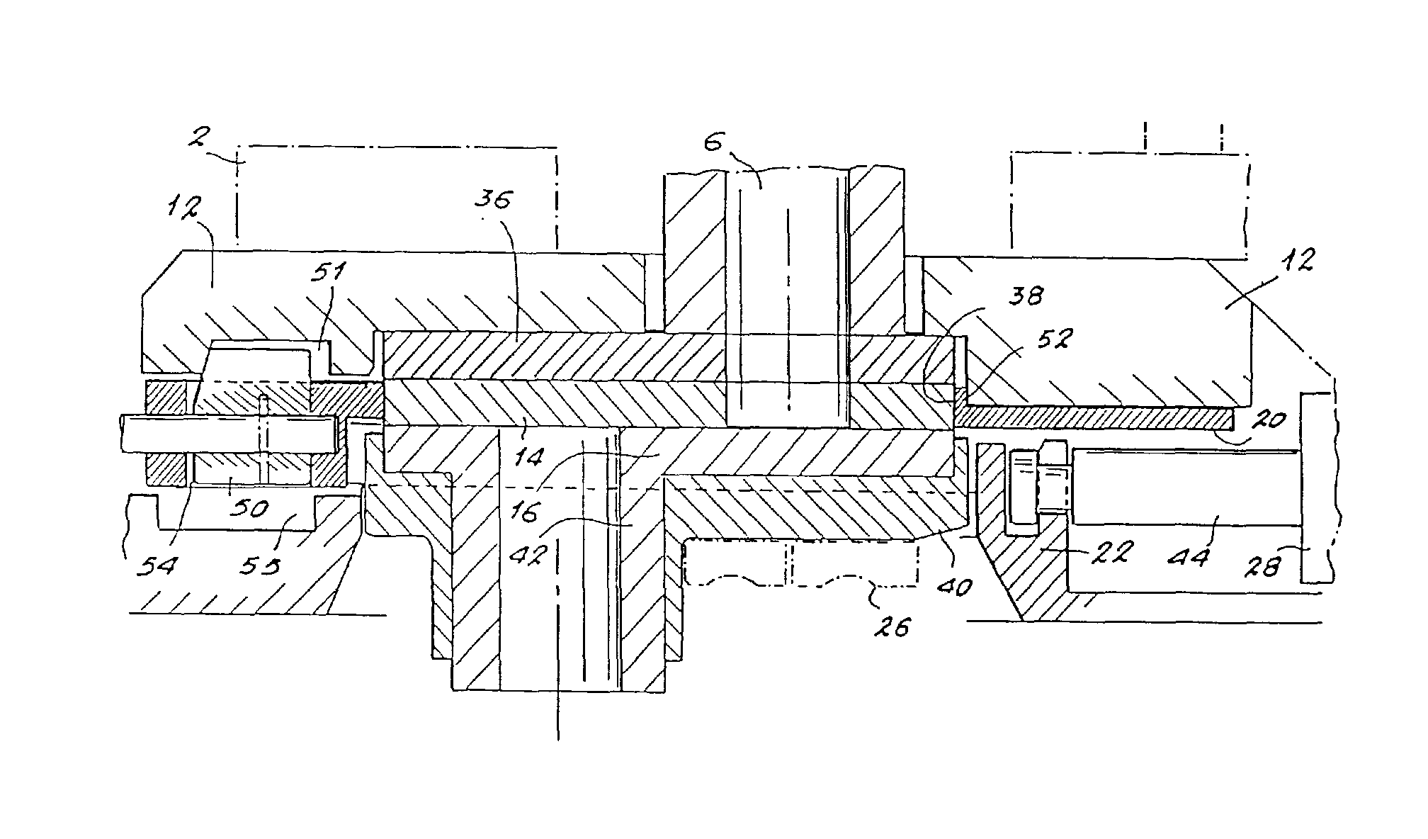
图3和图4表示出符合本发明的闸阀装置的另一实施例。此装置具有一个固定在冶炼炉桶1的外壁2上面的密实箱罩或框架12。一连接板36装设在箱罩12内的凹槽之中,并且安装在和胶合于龙头6的端部。板36的外表面构成了接合表面8。在此实施例中的固定板是由一耐火板本体14和一外壳38构成。而活动板由一耐火板本体16、一支座40和一排出嘴42组成,此排出嘴可以是单独的一件,或者是与耐火板16构成的整体结构。压缩装置26将在下面结合图4予以详细说明。这里只是指出,在该实施例中,以压缩方式保持固定板紧贴龙头6的接合表面以提供静力密封的装置是同压紧固定板14贴靠住活动板16以提供动力滑动密封的装置一样的。因而同一装置26实现两种显然不同的功能。Figures 3 and 4 show another embodiment of the gate valve assembly according to the invention. The device has a solid enclosure or
固定板14安置在用于固定板的托架20里面,而活动板16安置在用于活动板的托架22之中。气缸28的柱塞44被保持在用于活动板16的托架22之中的凹槽里面。气缸28可以沿着固定板14推移活动板16,以便以熟知的方式控制熔融金属排出冶炼炉桶1。The fixed
图4表示出图3所示实施例在一垂直平面(即垂直于柱塞44运动方向的平面)内的横截面视图。此图具体地表明一般由标号26代表的压缩装置的细节。所述装置26包括螺旋弹簧46,其一端紧靠箱罩12,而其另一端紧靠摇臂48,该摇臂把弹簧力(沿相反的方向)传递给活动板16,且再传给固定板14,并从此传递给连接板36。FIG. 4 shows a cross-sectional view of the embodiment shown in FIG. 3 in a vertical plane (ie, a plane perpendicular to the direction of movement of the plunger 44). This figure shows in particular details of the compression means generally indicated by the numeral 26 . Said means 26 comprises a
现在转向图3,来说明一下把固定板14的托架20牢牢地固定于箱罩12和活动板的托架22上的装置。该装置是由可转动地安装在固定板14的托架20上面的双位锁栓50组成的。在第一位置上,如图3所示,锁栓的制动件伸入到箱罩12中的凹槽51。而在其第二位置上(如图5所示),制动件伸入到设在活动板16的托架22中的凹槽53。在第一位置上,它相对于箱罩12止动固定板的托架20,而在第二位置上,它相对于活动板16的托架22而止动托架20。气缸的柱塞4 4的运动范围足以使包括两块板14和16的组件从压缩装置26解脱出来,此压缩装置紧压固定板14靠住龙头孔口的接合表面。Turning now to FIG. 3, the means by which the
由于使用双位锁栓50,同一装置,即气缸28,可以连续地实现两种显然不同的功能。首先,当锁栓50处于第一位置时,气缸28可以以通常的方式推移活动板。其次,当锁栓50处于第二位置时,气缸28可使有待更换的零件得以卸除并安装新的固定板14。在这方面,气缸28可使固定和活动二板14和16作为单一整体件被推移,同时所述各板借助于锁栓50而彼此相对地保持固定。Thanks to the use of the two-
在箱罩12上设有一固定台肩52。固定板14在其边缘处支靠在此台肩52上。锁栓50具有一表面54,此表面带有消除游动致使固定板14以固定板14的托架2 0为中介而保持贴紧台肩52的装置。表面54是,比如说,一种包括螺旋凸轮用以消除固定板14与固定板14的托架20之间相对于箱罩12产生游动的表面。这种结构的目的在于防止固定板14相对于接合表面的运动。活动板16可向固定板16传递显著的剪切力,这种力趋向于推移固定板14。如果没有保持固定板14就位的设置,那么它就会相对于龙头孔口的接合表面被向侧面推移,从而造成固定板14和接合表面的各接触面的不适当的磨损。A fastening shoulder 52 is provided on the
图5表示出图3中所示闸阀装置的一种变型实施例,其中阀处于开启(即准备更换)位置。同样的零件被赋予同样的参照标号。在图5中,锁栓50处于其第二位置,在此,它把固定板14的托架20和活动板16的托架22保持在一起。在气缸28的柱塞44连接于活动板的托架22的情况下,气缸28用来把由两个托架20、22连同设置在这些托架的凹槽中的板14、16所构成的组装件推向左方。这一运动的范围是以完全使固定板14和活动板16摆脱压缩装置26的作用。因而,板14、16可以轻易地卸掉,而不是非要象先有技术中的装置一般所要求的那样,打开一扇门等等。Figure 5 shows a modified embodiment of the gate valve arrangement shown in Figure 3 with the valve in the open (ie ready for replacement) position. Like parts are given like reference numerals. In FIG. 5, the
新板14、16以同样的通用方式安装。首先,新的固定板14嵌入固定板的托架20的凹槽内,抵住与接合表面想像中的延长部对齐(在制造公差范围之内)的箱罩12的一支承表面。活动板16随后被安置在固定板14上面,置于活动板16的托架2 2的凹槽之中。并不需要进行任何连接或解脱操作,因为在这种拆卸和安装过程中,气缸28的柱塞44始终固定在活动板16的托架22上。The
随后启动气缸28,以把两板的组装体相对于龙头沿侧向向内拉动,在锁栓装置50的作用下不需任何其他操作;锁栓装置50把两板14、16彼此相对地固定在一起。固定板14略微被导引和/或缩回,并且在固定板14开始搭盖冶炼炉桶的龙头6以前,其在压缩装置26的作用下滑动。The
图6和图7表示出连接板的两个变型的实施例。在图6中,龙头6的连接板是由围绕龙头孔口的圆形耐火板或环圈56构成,此板56牢固地固定于一金属支座58上,此支座可使它依靠设置在孔眼60中的诸如螺钉、螺栓、沉头螺栓等类似连接件刚性地固定到冶炼炉桶上。金属支座58的表面与接合表面8至少是部分共面的。在圆形耐火板56固装于金属支座58之后,通过对这两个表面作精细研磨可以获得这种共面特性。金属支座58的表面使人们可以有效地加宽固定板14贴合接合表面8的支承表面的面积,并避免作用于固定板14的非均布应力。Figures 6 and 7 show two variant embodiments of the connection plate. In Fig. 6, the connecting plate of the
人们在研磨一种耐火材料的同时又研磨一种诸如钢之类的金属并非易事。适于钢的研磨工具并不适于耐火材料,反之亦然,因此,图7的实施例使这一难题得以克服。挡块62刚性地固定于金属支座58上,并研磨得与圆形耐火板56共面,从而有效地加宽了固定板14贴合接合表面8的支承表面的面积。挡块62,从研磨工艺的角度来看,是由与耐火板56兼容的一种材料构成的;比如,这种材料可以是与板56相同的耐火材料。在这种情况下,挡块62和板56可以毫无困难地同时研磨。It is not easy for people to grind a refractory material and a metal such as steel at the same time. Abrasive tools that are suitable for steel are not suitable for refractory materials and vice versa, so the embodiment of Figure 7 overcomes this difficulty.
Claims (16)
Applications Claiming Priority (2)
| Application Number | Priority Date | Filing Date | Title |
|---|---|---|---|
| EP93401008.3 | 1993-04-19 | ||
| EP93401008A EP0621098B2 (en) | 1993-04-19 | 1993-04-19 | Method and apparatus for casting with a cement-free joint of a metallurgical vessel and a casting gate |
Publications (2)
| Publication Number | Publication Date |
|---|---|
| CN1107274A CN1107274A (en) | 1995-08-23 |
| CN1057718C true CN1057718C (en) | 2000-10-25 |
Family
ID=8214700
Family Applications (1)
| Application Number | Title | Priority Date | Filing Date |
|---|---|---|---|
| CN94190210A Expired - Fee Related CN1057718C (en) | 1993-04-19 | 1994-04-19 | Slide gate valve having a cementless joint between the valve and a metallurgical vessel |
Country Status (13)
| Country | Link |
|---|---|
| US (2) | US5400930A (en) |
| EP (1) | EP0621098B2 (en) |
| JP (1) | JP3259962B2 (en) |
| CN (1) | CN1057718C (en) |
| AT (1) | ATE220588T1 (en) |
| AU (1) | AU666624B2 (en) |
| BR (1) | BR9404968A (en) |
| CA (1) | CA2137372C (en) |
| DE (1) | DE69332116T3 (en) |
| ES (1) | ES2176196T5 (en) |
| MX (1) | MXPA94002807A (en) |
| RU (1) | RU2145534C1 (en) |
| WO (1) | WO1994023867A1 (en) |
Families Citing this family (13)
| Publication number | Priority date | Publication date | Assignee | Title |
|---|---|---|---|---|
| BE1005987A3 (en) * | 1992-06-16 | 1994-04-12 | Int Ind Eng Sa | Control device of casting speed. |
| ES2117110T3 (en) * | 1993-04-19 | 1998-08-01 | Vesuvius France Sa | SET OF REFRACTORY ELEMENTS FOR A CAST SHUTTER AND PROCEDURE TO CHANGE SUCH SET. |
| ATE178823T1 (en) * | 1995-02-17 | 1999-04-15 | Stopinc Ag | SLIDE CLOSURE SYSTEM FOR A CONTAINER CONTAINING MOLTEN METAL |
| ZA975908B (en) * | 1996-07-18 | 1998-03-30 | Stopinc Ag | Sliding gate valve for a vessel containing molten metal. |
| DE10033904A1 (en) * | 2000-07-12 | 2002-01-31 | Stopinc Ag Huenenberg | Slider closure for casting molten metal, as well as an associated fireproof plate unit |
| WO2005024069A2 (en) * | 2003-08-29 | 2005-03-17 | Stopinc Aktiengesellschaft | Tapping device for a crucible, especially for a converter |
| CN102006952B (en) * | 2008-04-17 | 2016-03-23 | 斯托品克股份公司 | Latch plate and the slip dead lock in the exit of the container for metal bath |
| JP5481374B2 (en) * | 2008-05-16 | 2014-04-23 | 黒崎播磨株式会社 | Sliding nozzle device |
| US20130048897A1 (en) * | 2011-08-31 | 2013-02-28 | P D K Llc | Exchangeable valve plate assembly for a molten metal slide gate valve |
| PL2979777T3 (en) * | 2013-03-27 | 2019-01-31 | Krosakiharima Corporation | Sliding nozzle device |
| CN103525973B (en) * | 2013-09-30 | 2015-07-29 | 马鞍山利尔开元新材料有限公司 | A kind of slide plate slag-stopping tapping converter mechanism |
| EP3587002B1 (en) * | 2018-06-26 | 2020-12-16 | Refractory Intellectual Property GmbH & Co. KG | Sliding closure for a metallurgical vessel |
| PL3930941T3 (en) * | 2019-02-28 | 2024-02-26 | Vesuvius Group, S.A. | Sliding gate valve comprising a carriage |
Citations (3)
| Publication number | Priority date | Publication date | Assignee | Title |
|---|---|---|---|---|
| GB2043217A (en) * | 1979-03-02 | 1980-10-01 | Flogates Ltd | Spring device for sliding gate valve |
| DE2924118A1 (en) * | 1979-06-15 | 1980-12-18 | Zimmermann & Jansen Gmbh | Bottom pour sliding stopper for pouring ladles - where spring pressure on overhanging end of sliding stopper plate is released when stopper is closed |
| US4415103A (en) * | 1979-09-07 | 1983-11-15 | Uss Engineers And Consultants, Inc. | Full throttle valve and method of tube and gate change |
Family Cites Families (16)
| Publication number | Priority date | Publication date | Assignee | Title |
|---|---|---|---|---|
| DE2027881B2 (en) * | 1970-06-06 | 1979-12-13 | Schloemann-Siemag Ag, 4000 Duesseldorf | Device for renewing the steel supply from the intermediate container to the mold of a continuous caster |
| JPS6015429B2 (en) * | 1973-02-13 | 1985-04-19 | 黒崎窯業株式会社 | Surface pressure load setting method for sliding nozzle equipment |
| BE841397A (en) * | 1975-05-30 | 1976-09-01 | SLIDE CLOSURE DEVICE INTENDED, IN PARTICULAR, FOR CONVERTERS | |
| NL187197C (en) * | 1978-09-25 | 1991-07-01 | Uss Eng & Consult | DEVICE FOR CONTROLLING THE FLOW OF LIQUID METAL. |
| US4545512A (en) * | 1981-01-19 | 1985-10-08 | Uss Engineers & Consultants, Inc. | Full throttle valve and method of tube and gate change |
| US4582232A (en) * | 1984-06-19 | 1986-04-15 | Flo-Con Systems, Inc. | Valve, clamp, refractory and method |
| DE3512798C1 (en) * | 1985-04-10 | 1986-02-06 | Stopinc Ag, Baar | Sliding closure for vessels containing molten metal |
| DE8514458U1 (en) * | 1985-05-15 | 1985-07-04 | Brohltal-Deumag AG, 5401 Urmitz | Slide plate |
| DE8528085U1 (en) * | 1985-10-02 | 1987-02-05 | Dahlhoff, Friedrich-Wilhelm, 5804 Herdecke | Slide valve for pouring out containers containing molten metal |
| AT386422B (en) * | 1986-11-13 | 1988-08-25 | Voest Alpine Ag | DEVICE FOR REMOVING HOLE STONES INSERTED IN THE TAPPING OPENING OF METALLURGICAL VESSELS |
| DE3731021A1 (en) * | 1987-09-11 | 1989-03-23 | Mannesmann Ag | RING FOR TURNOVER LOCK |
| DE4006064A1 (en) * | 1990-02-26 | 1991-08-29 | Zimmermann & Jansen Gmbh | LOCKING DEVICE FOR THE FLOOR POUR OPENING OF A WATER PAN |
| US5004131A (en) * | 1990-04-16 | 1991-04-02 | Bethlehem Steel Corporation | Molten metal slide gate valve |
| DE4023484A1 (en) * | 1990-07-24 | 1992-02-06 | Didier Werke Ag | Pouring tube - slides on head plate for exchange and controls metal flow by sliding in the pouring position |
| US5118016A (en) * | 1990-09-27 | 1992-06-02 | Martin & Pagenstecher, Inc. | Bottom pour tiles with self sealing joint for pouring liquid steel |
| FR2681804B1 (en) * | 1991-09-27 | 1993-11-19 | Boulonnais Terres Refractaires | IMPROVEMENTS TO THE SHUTTERS OF A CONVERTER CAST. |
-
1993
- 1993-04-19 DE DE69332116T patent/DE69332116T3/en not_active Expired - Fee Related
- 1993-04-19 ES ES93401008T patent/ES2176196T5/en not_active Expired - Lifetime
- 1993-04-19 EP EP93401008A patent/EP0621098B2/en not_active Expired - Lifetime
- 1993-04-19 AT AT93401008T patent/ATE220588T1/en not_active IP Right Cessation
-
1994
- 1994-03-17 US US08/214,286 patent/US5400930A/en not_active Ceased
- 1994-04-19 BR BR9404968A patent/BR9404968A/en not_active IP Right Cessation
- 1994-04-19 MX MXPA94002807A patent/MXPA94002807A/en not_active IP Right Cessation
- 1994-04-19 WO PCT/EP1994/001211 patent/WO1994023867A1/en not_active Ceased
- 1994-04-19 JP JP52277194A patent/JP3259962B2/en not_active Expired - Fee Related
- 1994-04-19 AU AU65693/94A patent/AU666624B2/en not_active Ceased
- 1994-04-19 RU RU94046258A patent/RU2145534C1/en active
- 1994-04-19 CA CA002137372A patent/CA2137372C/en not_active Expired - Fee Related
- 1994-04-19 CN CN94190210A patent/CN1057718C/en not_active Expired - Fee Related
-
1997
- 1997-09-29 US US08/939,332 patent/USRE36364E/en not_active Expired - Lifetime
Patent Citations (3)
| Publication number | Priority date | Publication date | Assignee | Title |
|---|---|---|---|---|
| GB2043217A (en) * | 1979-03-02 | 1980-10-01 | Flogates Ltd | Spring device for sliding gate valve |
| DE2924118A1 (en) * | 1979-06-15 | 1980-12-18 | Zimmermann & Jansen Gmbh | Bottom pour sliding stopper for pouring ladles - where spring pressure on overhanging end of sliding stopper plate is released when stopper is closed |
| US4415103A (en) * | 1979-09-07 | 1983-11-15 | Uss Engineers And Consultants, Inc. | Full throttle valve and method of tube and gate change |
Also Published As
| Publication number | Publication date |
|---|---|
| CA2137372C (en) | 2007-06-26 |
| ES2176196T5 (en) | 2006-05-01 |
| ATE220588T1 (en) | 2002-08-15 |
| BR9404968A (en) | 1999-06-15 |
| EP0621098B2 (en) | 2005-11-23 |
| EP0621098B1 (en) | 2002-07-17 |
| JPH07508223A (en) | 1995-09-14 |
| JP3259962B2 (en) | 2002-02-25 |
| ES2176196T3 (en) | 2002-12-01 |
| RU2145534C1 (en) | 2000-02-20 |
| MXPA94002807A (en) | 2005-01-28 |
| CA2137372A1 (en) | 1994-10-27 |
| CN1107274A (en) | 1995-08-23 |
| WO1994023867A1 (en) | 1994-10-27 |
| AU666624B2 (en) | 1996-02-15 |
| DE69332116T2 (en) | 2003-03-06 |
| EP0621098A1 (en) | 1994-10-26 |
| AU6569394A (en) | 1994-11-08 |
| US5400930A (en) | 1995-03-28 |
| USRE36364E (en) | 1999-11-02 |
| DE69332116D1 (en) | 2002-08-22 |
| DE69332116T3 (en) | 2006-09-28 |
| RU94046258A (en) | 1996-10-27 |
Similar Documents
| Publication | Publication Date | Title |
|---|---|---|
| CN1057718C (en) | Slide gate valve having a cementless joint between the valve and a metallurgical vessel | |
| EP2045310B1 (en) | Improved coke drum de-heading system | |
| US4063668A (en) | Ladle gate valve | |
| TWI515300B (en) | Sliding closure for a container containing molten metal and cassette for a sliding closure | |
| CA1067672A (en) | Apparatus for regulating the flow of molten metal | |
| CN1079040C (en) | Sliding gate valve for vessel containing molten metal | |
| US4978108A (en) | Gas washing sink without integral closure member | |
| JPH1060516A (en) | Slide gate valve of vessel for incorporating molten metal | |
| JPH0735245A (en) | Slide valve | |
| JP2860284B2 (en) | Refractory plate structure for sliding gate valve assembly | |
| GB2122315A (en) | Pressure fluid teeming valve and method | |
| KR100328117B1 (en) | Injection pipe fittings for molten metal containers | |
| AU762762B2 (en) | Iron ore slide valve with internal support clamp | |
| AU667275B2 (en) | Slide gate valve having replaceable refractory valve plate assembly and method of replacing the same | |
| JPS5841142B2 (en) | Sliding gate closing mechanism to control the flow of molten metal | |
| KR20200083477A (en) | Self-locking internal nozzle system | |
| JPS59225876A (en) | Slide type sealing device for steel or metallurgical container | |
| EP1838478B1 (en) | A sliding gate valve for a metallurgical vessel | |
| JP2026505457A (en) | Assembly for casting molten metal including a sand casting mold, a short shroud, and a mold/shroud coupling mechanism, casting apparatus, and method for casting molten metal parts | |
| DE3500866A1 (en) | Sliding gate for the nozzle on metallurgical vessels, in particular steel-casting ladles | |
| KR0132368Y1 (en) | Casting Thickness Variable Molds for Continuous Casting | |
| JPH10132093A (en) | Valve device | |
| KR19980065827U (en) | Gate sealing device of sedimentation channel | |
| JP3427120B2 (en) | Magnetic suction device for temporary fixing of gate plate at molten metal discharge gate | |
| WO1992009839A1 (en) | Slide valve |
Legal Events
| Date | Code | Title | Description |
|---|---|---|---|
| C06 | Publication | ||
| PB01 | Publication | ||
| C10 | Entry into substantive examination | ||
| SE01 | Entry into force of request for substantive examination | ||
| C14 | Grant of patent or utility model | ||
| GR01 | Patent grant | ||
| C17 | Cessation of patent right | ||
| CF01 | Termination of patent right due to non-payment of annual fee |
Granted publication date: 20001025 Termination date: 20100419 |