The technology for eliminating of signal distortion
The present invention relates to device in order to the distortion of erasure signal multipath.
Though the present invention describes with " eliminating oneself to send the ghost of TV signal " this technical term, it can be used for eliminating from widely, the multipath composition or the ghost image of various transmission signals.Work out a lot of methods already and eliminated the multipath distortion (" removing ghost ") of vision signal.Put it briefly, these methods all are to utilize the acceptance test signal to compare with the test signal of an ideal type, eliminate the method for the multi-path component of received signal to constitute a filter in receiver.
Making one of in this way main difficulty is exactly to select suitable test signal.Some system the saltus step of the vertical synchronization component of vision signal as test signal.Other system all increases a training signal and is used for " removing ghost " specially in broadcast singal.Nominally this training signal was added in the between-line spacing in the vertical blanking cycle of vision signal, and the form of employing 2T pulse or sin x/x type signal.For 2T pulse and sin x/x the two or vertical synchronizing signal, the normal frequency band limits of broadcast singal is often taken into account " removing ghost " performance.In addition, because the power density of these signals is quite low, this tends to reduce " removing ghost " performance under noisy situation.
The signal that now has been used as the another kind of type of training signal is a pseudo random sequence that is inserted in the horizontal interval.Pseudo random sequence has effective power density and can be transmitted.Usually, the pseudo random sequence that is transmitted is relevant with sequence in the errorless type at receiver place in time-domain.Relevant result produces the pulse of " direct signal and each multi-path signal occur ".Mensuration corresponding to the pulse of direct signal and corresponding to the interval between the pulse of multi-path signal so that the information about the multi-path signal time delay to be provided.The relative amplitude of measuring pulse is to provide the information about multi-path signal intensity.Utilize these timings and amplitude information to go out a filter that is suitable for eliminating multi-path signal by structure.Please read the United States Patent (USP) 4,594,479 and 4,578,544 of the ghost cancelling system that for example uses pseudo random sequence, this paper lists these patent documentations for your guidance.The shortcoming that such time-domain is handled is, tend in relevant output signal to produce tangible secondary lobe at frequency band limits that sends the channel in the signal and noise, this makes that to have a detection of the multi-path component that prolongs in short-term with respect to direct signal smudgy.
Also worked out the system that some frequency domains that comprise that multipath distortion (or ghost image) is eliminated are handled already.In these systems, the training signal that has sent is carried out Fourier transform, an errorless training signal is calculated Fourier transform, with the Fourier transform that sent Fourier transform divided by errorless training signal, and this merchant carried out inverse Fourier transform, to draw a sequence, this sequence is corresponding to the one group of filter factor that constitutes a correcting filter.See also people such as W.Ciciora at Consumer Electronics(consumer electronics), the IEEE proceedings, Vol.CE-25, in February, 1979, the the 9th to the 44 page of article that is entitled as " A Tutorial on Ghost Cancelling in Television Systems " (eliminating the introduction of ghost in the television system) of going up publication is as an example, and this article is listed in for reference here.
Usually, in consumer products, can not comprise the Fourier transform device, because realize that the required hardware of this function is very considerable.Fourier transform hardware and processing time are by using fast Fourier transform (FFT) to be reduced, yet, in order to ensure using FFT to obtain reliable result, the training signal of specific type should be provided, for example help to carry out the form that the FFT signal is normally taked the finite duration sequence.Moreover for connecing the efficient that preface realizes FFT, this sequence must have a series of many sample values that equal 2 power.
The optimal sequence that is used as training signal is maximum pseudo random sequence, can be in this sequence each bit related gain that all offers the best.Maximum pseudo random sequence has (2
n-1) bit length (wherein n is an integer).Therefore, in general, maximum pseudo random sequence does not help FFT to handle.
The included multipath elimination of the present invention has the advantage of pseudo random sequence training signal and the hardware efficiency of the FFT that frequency domain is handled.(2-1) bit pseudo-random sequence training signal is inserted in the horizontal line of TV signal.Before sending at the transmitter place, or after receiving this TV signal at the receiver place, this training signal is videoed one 2 by grating
nThe sample value space.The signal that receives through grating reflection carries out conversion through the FFT device, and with errorless, carry out " deconvoluting " through the FFT of the identical sequence of grating reflection, with generation multipath correction filter factor.
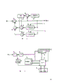
Fig. 1 and Fig. 3 illustrate and embody alternative block diagram that goes to the ghost system of the present invention;
Fig. 2 illustrates the block diagram that removes the ghost filter segment shown in Fig. 1;
Fig. 4 illustrates the flow chart of presentation graphs 3 processing of circuit steps;
Fig. 5 illustrates a series of pseudo random sequence presentation graphs, has the ghost time delay indication that detects in order to ghost in each sequence among the figure;
Fig. 6 illustrates in order to determine the flow chart of a kind of exemplary algorithm of ghost time-delay from " constituting the deconvoluting of finite duration sequence of the repetition of pseudo random sequence shown in Figure 5 ".
The process of elimination multi-path signal is usually directed to determining of transmission channel characteristics and filter is programme to provide the transfer function that becomes the transmission channel inverse, so that eliminate multi-path component.If be sent out signal X(ω) expression, received signals Y(ω) expression, channel characteristic H(ω) expression, then
Y(ω)=X(ω)H(ω)(1)
Y(ω in the formula), X(ω) and H(ω) all be time-domain signal y(t), x(t) and time domain characteristic h(t) Fourier transform.Channel characteristic H(ω) can be by the signal Y(ω that sends a known signal in predetermined training interim and receive in training interim) determine divided by the form that is stored of training signal.That is
H(ω)=Y(ω)/X(ω)(2)
Determine Function Y (ω)/X(ω) process be called as " deconvoluting ".
Signal of present consideration is made up of the finite duration sequence of a repetition, and each sequence takes place on the I of interval.As everyone knows, the convolution of sort signal circulates, and that is to say, all available known array in any a moment in the duration I of this signal carries out convolution, produces an identical correlated results, although displacement in time.That is, if two a moment I (t) and I (t+ △ t) respectively by convolution, then correlated results moves apart △ t.In frequency domain, the product of the Fourier transform of all signals that the convolution of all finite duration sequences is briefly rolled up exactly.Y(t) and convolution s(t) corresponding to product Y(ω) S(ω).Consider S(ω)=1/X(ω), H(ω then)=Y(ω)/X(ω) also be a convolution function, and will circulate for the finite duration sequence.
Can determine the time of delay of the multi-path component that exists in received signal from the logarithmetics cepstrum of formula (2), X(ω in the formula) and Y(ω) be respectively training signal x(t) and received signal y(t) power spectrum.This logarithmetics cepstrum is quotient Y(ω)/X(ω) the inverse Fourier transform of logarithm.Usually, this logarithmetics cepstrum produces pulse train, and each pulse all determines the multi-path component relevant with time data, and the selected interval of deconvoluting corresponding to execution.In another way, each pulse in the logarithmetics cepstrum all indicates the relative position of the non-zero coefficient amplitude of ghost filter, and this filter is used corresponding to the transfer function of sendaisle anti-espionage and programme.
The actual enforcement of determining the said method of multi-path signal component time-delay is the method that must utilize FFT in consumer's television receiver.This often limits training sequence and takes place in 2 sampling periods.In order to finish the maximal correlation response in the convolution process, this training sequence should (a) have the such big amplitude that this system signal form allows; And (b) be with the form of maximum pseudo random sequence (for example 2-1 bit code).
The bi-level signal that maximum pseudo random sequence is made up of the predetermined sequence of binary one and 0.When they being used as a training signal, then the amplitude modulation(PAM) through carrier wave is sent out away later.Receiving the reconciliation timing, this sequence is analog form normally.Fft processor is a digital device, for example comes work by binary signal, for this reason, must earlier received signals be converted into digital form through an A/D converter (ADC).This ADC is synchronous with the synchronized component that is sent out signal usually.The sampling rate of ADC is selected as four times of color subcarrier usually, and phase locking is to the colour burst component.For 1 and 0 sequence that this ADC faithful reappearance is sent out, the sequence that is sent out should be regularly synchronous with the sampling of ADC.In other words, if ADC with four times sample at rates of colour subcarrier frequency, then the bit of this training signal should be produced with the speed of four times of colour subcarrier frequencies or with the subharmonic speed of the even number of colour subcarrier frequency at the transmitter place.In addition, the beginning of this sequence should be with reference to the predetermined time data such as the horizontal synchronization pulse edge.Under these conditions, specific transmission sequence is corresponding to the predetermined sequence of sample value, and that is a pseudo random sequence, and for example 255 bits that produce with four times of subcarriers will be represented by 255 continuous sample values at receiver place.
As mentioned above, for the FFT conversion, the sample value sequence must contain 2
nIndividual sample value.2
nThe pseudo random sequence of-1 bit is converted into 2 in the FFT by the grating reflection handles
nIndividual sample value.The grating reflection is the process of a signal of interpolation, and this signal is to take place on a given sample value space, to occupy a bigger or less sample value space.Be entitled as " Videosignal Time Expansion/Compression Apparatus Using Programmed Output Values " (planting vision signal temporal extension/compression device) with the programmable output valve, as a reference U.S. Pat 4 here side by side, 914,507 have exemplarily described degree grid mapping device.Be somebody's turn to do (2
n-1) grating of bit pseudo-random sequence training signal reflection can carry out at the transmitter place, also can carry out at the receiver place.
At last, in order to utilize the finite duration sequence of circular convolution, this training signal should comprise this pseudo random sequence of several repetitions.Fig. 5 illustrates a sequence that contains three repetitions is arranged training signal within the delegation of the vision signal that sends schematic diagram.
With reference to Fig. 1, baseband video signal is applied on the video encoder 10, this signal by the form of the composite video signal of standard for example NTSC form.The vision signal of having encoded is applied on the input of multiplex switch 16.The pseudo random sequence of maximum length (below abbreviate " PRS " as) is supplied with by pseudo-random sequence generator 12, and be applied on second input of this multiplex switch 16, this multiplex switch 16 is controlled by timing circuit (not drawing among the figure), PRS during one of the perpendicular separation of the composite video signal predetermined between-line spacing is applied on the transmitter 18, and in other time, composite video signal is applied on the transmitter.Transmitter 18 these multiplexed signalss of control are through the transmission of broadcast channel, cable etc.
PRS generator 12 can be a read only memory ROM, and its each continuous memory cell is to be programme by the successive bits of this sequence.Timing in it and address circuit are controlled for example continuous, the identical sequence (for example 3) among one 255 bit PRS of this ROM output.Perhaps, generator 12 also can be one (2
n-1) bit shift register makes it contain required sign indicating number and makes it locked to export the bit of above-mentioned sign indicating number in the serial bit stream.Be coupled to a low pass filter from the PRS of generator 12 output, with the bandwidth constraints of PRS bandwidth to composite video signal.If the grating of this PRS reflection is to carry out at the transmitter place, then the grating projection instrument 13 shown in the dotted line is located between generator 12 and the low pass filter 14.Grating projection instrument 13 is with 2
nThe training signal that takes place on-1 sample value space is converted into 2
nThe signal that takes place on the sample value space.
If being binary format, this vision signal will be converted to analog form for 18 li at transmitter, and this generator 12 is ROM forms, then the form through the grating of low-pass filtering reflection of this PRS can be programmed preface with binary format in this ROM, thereby can cancel grating projection instrument 13 and low pass filter 14.
The timing of PRS circuit 12 should be arranged to provide a synchronous bit sequence of one-component (for example colour subcarrier) with composite video signal, so that can carry out the synchronous detecting of PRS at the receiver place.
The signal that is sent out is detected by the tuning circuit 22 of a routine at the receiver place, and is applied on intermediate frequency (IF) treatment circuit 24.The signal that is drawn by this IF circuit is coupled to ADC 26, for example changes it into the pulse code modulation (pcm) of binary format sample value.The frequency of the sampling value of this ADC is for example synchronous with colour subcarrier, so that the sample value space of this PRS sequence meets the sample value of predetermined number.
The sample value that is produced by ADC is coupled to ghost filter 42, and this filter can be eliminated the multi-path signal component basically.Vision signal by filter 42 outputs is applied on the conventional video processing circuit (draw among the figure and show), and brightness and chromatic component are separated in this circuit shows or record with being controlled to.
Sample value from ADC 26 also is added on the FFT treatment circuit 30, and the frequency spectrum of this signal produces within it.If this PRS is videoed by grating at the transmitter place, then the sample value with ADC is directly coupled on the FFT 30.On the contrary, if this PRS is not videoed by grating at the transmitter place, then the sample value of ADC 26 outputs will be applied on the grating projection instrument 28, with 2 of this PRS
n-1 sample value is converted to 2 sample values at interval at interval.The grating image signal that is provided by projection instrument 28 then is coupled on the fft circuit 30.
Fft circuit 30 is controlled confirming that between-line spacing contains this PRS by timing circuit (among the figure draw show), and only carries out fast Fourier transform on this part of received signal.The output signal of fft circuit 30 is corresponding to the signal Y(ω in the formula (1)).Signal Y(ω from fft circuit 30) in linearity/logarithmic converter 32, be converted to logarithmic form log(Y(ω)), this logarithm value is coupled on the minuend input of subtraction circuit 36.
The PRS training signal X(ω of grating reflection) errorless kenel for example is stored among the ROM 44.This signal is converted into logarithmic form in linearity/logarithmic converter 34, and is applied on the subtrahend input of subtraction circuit 36.Subtracter 36 provides signal log(Y(ω))-log(X(ω)), it equals log(Y(ω)/X(ω)).
Deposit signal in the circuit 44 in corresponding to the repetition of PRS.Timing from the generation of the sample value of circuit 44 will be arranged corresponding to the specific interval that is received sequence.But, should be noted that because the circular convolution characteristics of finite duration sequence, therefore there is no need the timing of the sequence that restricting circuits 44 provides, with part corresponding to a uniqueness of received signals.
The logarithmic difference that is provided by subtracter 36 is applied on the fft circuit 38, so that log(Y(ω to be provided)/X(ω)) inverse Fourier transform, it is corresponding to logarithmetics cepstrum H(ω).This logarithmetics cepstrum is a pulse train, and the relative time that it takes place is corresponding to the time delay interval of each multi-path component.This inverse transformation is applied on the circuit 40, and this circuit produces the time-delay coefficient corresponding to each multi-path component.In fact, circuit 40 is compared the pulse that fft circuit 38 provides with timing data, to produce the time-delay coefficient.
The coefficient of will delaying time is applied on the ghost filter 42.In this embodiment, suppose that the ghost filter includes the element of a plurality of Variable delay, each element all has the time delay interval by the control of a time-delay coefficient.(please refer to United States Patent (USP) 4,727,424, this is an example that is used for the variable delay circuit of multipath distortion cancellation element.) Fig. 2 illustrates such embodiment who removes the ghost filter.Filter shown in Figure 2 is a recursion type, has a plurality of feedback networks, and each feedback network comprises a variable delay and a scaling circuit.Input signal is applied to the minuend input of subtraction circuit 50, the output signal that subtraction circuit 50 provides is coupled to each feedback network (58,62), on the input of (60,64), wherein, output signal postponed in each delay element (58,60) by the different time intervals, and carried out amplitude calibration in each scaling circuit (62,64).Each feedback network is supplied with a signal, and this signal is corresponding to the estimated value of one of each multi-path signal component.Each feedback signal is sued for peace in adder 68, should and count to be applied on the subtrahend input of subtraction circuit 50.The feedback signal that is applied to subtraction circuit 50 is eliminated the multi-path component in the received signal basically.
The amplitude calibration coefficient produces and is applied on the scaling circuit 62-64 via circuit element 52-56.This is to compare with the output signal of subtraction circuit 50 by the errorless kenel of the training signal that in time-domain receiver memory is stored up to carry out.The sequence signal that receives and the difference of storage sequence for example utilize the lowest mean square process to estimate, to produce calibration coefficient.These methods are known for the multipath cancellation element, thereby repeat no more.Yet with reference to U.S. Pat 4,686,510, this article has been explained in detail in order to draw an exemplary means of amplitude calibration coefficient.
Multi-path component is eliminated the operation of system and is carried out as follows: estimate in frequency domain at the training signal that an interim receives, to determine the relative delay of each multi-path signal component, and the generation retardation coefficient, it is applied on each corresponding of variable delay element in the filter 42.Next interval and predetermined number with back court interim, this filter circuit is analyzed the training signal of these receptions, to produce the amplitude calibration coefficient iteratively.Note that the calculating of multipath delay and the calculating of amplitude calibration coefficient have nothing to do, although it is not necessarily irrelevant conversely.Yet, in case this system determines first group of retardation coefficient and is initialised usually, the calculating of retardation coefficient and amplitude calibration coefficient was carried out concurrently in each interim, whereby, allowed this system to adjust to the multi-path signal of those variations that produce such as the aircraft by motion rapidly.
Should be noted that FFT handles and goes the ghost filter process only to carry out on in-phase signal, or with relevant component of the quadrature phase in received signal of integrated treatment on carry out.Yet FFT handles preferably and carries out on the comprehensive or relevant component of quadrature phase of received signal.
With reference to Fig. 1, the hardware element of this system is simplified by using time division multiplexing to handle.For example, training signal can be used as 2
n-1 bit serial signal storage is (2
n-1) in the bit shift register, perhaps can directly produce by a n bit shift register.During non-existent this spacer segment of the training signal that is transmitted, two signals can be applied on the grating projection instrument 28, and it is videoed by grating, and FFT handles, and to number conversion, and are stored in the memory, to use when the training signal that receives and handle can obtain.In addition, the output of subtraction circuit 36 with from the signal of grating projection instrument by time division multiplexing, so that fft circuit 30 can be in order to carry out inverse transformation.In this manner, element 34,44 and 38 can be saved under the prerequisite of two multiplex switch of cost and some memory.
Fig. 3 is illustrated in the receiver in order to another embodiment of the device that multi-path component eliminates to be provided.In this embodiment, for example comprise that can handle level 80 through 1F from the signal of the multi-path component of conventional tuning circuit be coupled on the ADC 82.PCM sample value from ADC 82 is coupled on ghost filter 90, RAM circuit RAM 86 and the microprocessor element μ pc 92.The signal of locating IF circuit 80 also is coupled on the sync separator 84, and this sync separator 84 provides vertical and horizontal-drive signal to μ pc 92, to set up necessary timing reference signal.The errorless kenel of training signal is provided by PRS ROM 94.The all FFT and the calculating of retardation coefficient are carried out by μ pc 92, in response to errorless training signal among training signal that has received among the RAM 86 and the PRS ROM 94.
The operating process of device shown in Figure 3 is shown in greater detail in the flow chart of Fig. 4 and Fig. 6.Yet before describing this operation, elder generation is with reference to Fig. 5 in order to illustrate the processing capacity part.
As what above show, handle and circular convolution for the ease of FFT, wish to transmit this training signal with as a finite duration sequence.This is represented by uppermost waveform DS among Fig. 5, delegation's (being preferably in vertical blanking period) in this vision signal of its graphical representation of exemplary, this vision signal comprises: repeat S1, S2 and S3 horizontal synchronization pulse SYNC, colour burst benchmark BURST and pseudo random sequence for three times.If signal DS is sent out in multi-path environment, then it will comprise a composite signal when receiving, and the process that this signal comprises this signal DS and itself postpones, becomes the kenel that subtracts.For example, received signal can comprise: the kenel after signal DS and its postpone is signal G for example, signal G closely be shown in signal DS below.Signal G represents to have postponed with respect to direct signal DS the multi-path signal of time interval t1.
Postpone computational process relate to utilize stored training signal once repeat received signal is deconvoluted.Once the repeating of this training signal has I at interval, and I equals T second at interval.Deconvolute in order to carry out, do not require that stored training signal aligns again in time with the single full weight of the training signal that is sent out, and stored training signal is deconvoluted with any a slice duration T of this transmission signal, but the interval of wishing not select the initiating terminal of the close S1 of repetition or answering the tail end of S3 is to avoid end effect.
Supposing deconvolutes carries out therebetween at the interval of duration T I-1, and detects a multi-path component G3.This component can be corresponding to time t3 with respect to the delay of direct signal, that is a ghost is equivalent to ghost G, but a period of time that moved right is about t3-t1.In this case, testing result is that to be stored signal relevant with the delay kenel that repeats S1.In another way, detected ghost may be the relevant result of delay kenel who is stored signal and repeats S2 or S3.In order to solve this fuzzy ghost image, carry out the calculating of deconvoluting of twice increase, one is comprising that more than half repeats on a slice of received signal of S2, and another is comprising that more than half repeats on a slice of S1.Represent with the interval of I-2 and I-3 mark respectively for these two.For for simplicity, suppose that three interval I-1, I-2 and I-3 are that " end-to-end " arranges, the ghost G1 with same delay time (t1) is detected in each interval, and then ghost has quite short delay, and this delay equals time t1.In addition, if ghost G2 at interval I-1 and I-2 rather than in I-3, be detected, then ghost G2 since in the I-3 of interval, take place relevant and at least time of delay T.Should be noted that delay calculating is relevant at interval with specific convolution.For this reason, if the delay of ghost G2 is calculated as t in I-1 and two intervals of I-2, then its t2 time of delay with respect to direct signal equals t and adds last repetition time T, i.e. t2=t+T.In like manner, only be detected in the I-1 of interval if having the ghost G3 of relative delay ti, then its absolute delay t3 equals ti+2T.
Owing to do not wish to use near for the first time and the intervals that are received training signal at last two ends of repeating, thereby the interval of deconvoluting can not be " end-to-end ".If two intervals are in fact such as overlapping at the interval of Fig. 5 I-3 and I-2, then detected identical ghost will occur by the identical computing relay time in these intervals.
The number of repetition that is included in the PRS in this training signal is the selection in a kind of design, yet detection sensitivity is bigger for the PRS with a greater number bit.If the bit rate of this PRS equals four times of color subcarrier of this vision signal, then three sequences of 255 bits or six sequences of 127 bits adapt to a between-line spacing easily.Moreover if the delay that multi-path component does not present greater than the duration T of the single repetition of PRS is known, then multipath postpones and can calculate with deconvoluting of carrying out on the monospace.In this case, only require that in this training signal full weight of PRS is multiple.Yet, should be attached to respectively on the full weight multiple front end and tail end corresponding to the tail end of identical PRS and the bit of front end, to allow to do circular convolution and eliminating end effect.
When considering above-mentioned discussion, come with reference to Fig. 3, Fig. 4 and Fig. 6.When this system is energized, go ghost or multipath to eliminate system once receiving vertical sync pulse be initialised (100).μ pc 92 count level lock-out pulses when its arrives the line number TS contain training signal till (101).If the training signal that is transmitted is videoed by grating at the transmitter place, then μ pc controls the training signal (102) that RAM 86 is transmitted with storage.From another point of view, if this training signal is not videoed by grating, then μ pc 92 can be programmed preface, to carry out the grating image function and the form device of grating reflection is gone among the RAM 86.Can not get at present because suppose the microprocessor that can carry out the economy of FFT in real time, therefore the training signal that has received is deposited in the memory.
In case the training signal that is transmitted is caught in RAM 86, μ pc just takes out training signal from RAM 86, and carries out FFT(103 on training signal).The power spectrum coefficient that produces is deposited among the RAM 86.On as complete three sequence S1, the S2 of a unit and S3, carry out FFT, yet, be preferably in 2 of the interval of deconvoluting corresponding to needs
nCarry out FFT separately on the sample value sheet.In this, the errorless training signal of having stored (the once repetition of PRS) takes out from ROM 94, and the power spectrum coefficient that deposits RAM 86 in also is removed, and goes up and carries out deconvolute (104) at an interval of received signal (for example interval I-1).The logarithm result of convolution is stored, and then this result is carried out inverse Fourier transform (105), to produce the logarithmetics cepstrum corresponding to multipath time of delay on the I-1 of interval.To estimate these time of delays (106 and Fig. 6 in 200).If do not detect ghost (multi-path signal) (202), then this system returns step 101.If detect ghost, then store this result (204), and check to determine whether on all intervals, having carried out deconvolute (206).Deconvolute if finished, then take out the delay result (210) that this has been stored, be all identical results at interval make comparisons (212).Suppose at interval for three in the present embodiment.In all three intervals, all be detected (212) if ghost Gi has identical time-delay ti, then produce retardation coefficient (214) corresponding to time ti.If ghost Gi is detected, but in all three intervals, do not have identical delay, then the same delay (216) of these ghosts of estimation in interval 1 and 2.If these are the ghost Gi with same delay in interval 1 and 2, then be that these ghosts produce the retardation coefficient (218) corresponding to (ti+T).At last, if detected ghost Gi only takes place in interval 1, then to the retardation coefficient (220) of these ghosts generations corresponding to (ti+2T).Then these retardation coefficients are applied on the ghost filter 90.
Returned for 206 steps, as look into deconvoluting on all intervals and all do not finish, then index I adds 1(108), this system turned back to for 104 steps.
Go ghost filter 90 similar to exemplary filters shown in Figure 2, it comprises the circuit that calculates the amplitude calibration coefficient.Replace filter 90 and removed the latter circuit, and the amplitude calibration coefficient can be calculated by μ pc 92.In this case, the output signal that is provided by filter 90 is coupled to μ pc 92 for calculating with (dotting).
Refer again to Fig. 4 operation in this manner.At computing relay coefficient (106) and after being applied to filter 90, μ pc is set up to count down to the row (110) that contains training signal again.During this between-line spacing, by subtracter 50(Fig. 2) the sample value difference that provides deposits memory (111) in.With these differences compare with the errorless kenel of the training signal that can obtain from ROM 94 (112).According to comparative result, produce amplitude calibration coefficient (113,114) by a kind of known algorithm, and these coefficients are applied on the scaling circuit in the filter 90.This system be arranged the calibration coefficient on several intervals of iterative computation, or it arranged alternately to recomputate by Fig. 4 like that postpone and the amplitude calibration coefficient.