CN1059986C - Method of controlling terminal crimping apparatus - Google Patents
Method of controlling terminal crimping apparatus Download PDFInfo
- Publication number
- CN1059986C CN1059986C CN95121704A CN95121704A CN1059986C CN 1059986 C CN1059986 C CN 1059986C CN 95121704 A CN95121704 A CN 95121704A CN 95121704 A CN95121704 A CN 95121704A CN 1059986 C CN1059986 C CN 1059986C
- Authority
- CN
- China
- Prior art keywords
- crimping
- crimper
- height
- crimping device
- value
- Prior art date
- Legal status (The legal status is an assumption and is not a legal conclusion. Google has not performed a legal analysis and makes no representation as to the accuracy of the status listed.)
- Expired - Lifetime
Links
Images






Classifications
-
- H—ELECTRICITY
- H01—ELECTRIC ELEMENTS
- H01R—ELECTRICALLY-CONDUCTIVE CONNECTIONS; STRUCTURAL ASSOCIATIONS OF A PLURALITY OF MUTUALLY-INSULATED ELECTRICAL CONNECTING ELEMENTS; COUPLING DEVICES; CURRENT COLLECTORS
- H01R43/00—Apparatus or processes specially adapted for manufacturing, assembling, maintaining, or repairing of line connectors or current collectors or for joining electric conductors
- H01R43/04—Apparatus or processes specially adapted for manufacturing, assembling, maintaining, or repairing of line connectors or current collectors or for joining electric conductors for forming connections by deformation, e.g. crimping tool
- H01R43/048—Crimping apparatus or processes
-
- H—ELECTRICITY
- H01—ELECTRIC ELEMENTS
- H01R—ELECTRICALLY-CONDUCTIVE CONNECTIONS; STRUCTURAL ASSOCIATIONS OF A PLURALITY OF MUTUALLY-INSULATED ELECTRICAL CONNECTING ELEMENTS; COUPLING DEVICES; CURRENT COLLECTORS
- H01R43/00—Apparatus or processes specially adapted for manufacturing, assembling, maintaining, or repairing of line connectors or current collectors or for joining electric conductors
- H01R43/04—Apparatus or processes specially adapted for manufacturing, assembling, maintaining, or repairing of line connectors or current collectors or for joining electric conductors for forming connections by deformation, e.g. crimping tool
- H01R43/048—Crimping apparatus or processes
- H01R43/0488—Crimping apparatus or processes with crimp height adjusting means
-
- B—PERFORMING OPERATIONS; TRANSPORTING
- B30—PRESSES
- B30B—PRESSES IN GENERAL
- B30B15/00—Details of, or accessories for, presses; Auxiliary measures in connection with pressing
- B30B15/0094—Press load monitoring means
-
- B—PERFORMING OPERATIONS; TRANSPORTING
- B30—PRESSES
- B30B—PRESSES IN GENERAL
- B30B15/00—Details of, or accessories for, presses; Auxiliary measures in connection with pressing
- B30B15/14—Control arrangements for mechanically-driven presses
-
- H—ELECTRICITY
- H01—ELECTRIC ELEMENTS
- H01R—ELECTRICALLY-CONDUCTIVE CONNECTIONS; STRUCTURAL ASSOCIATIONS OF A PLURALITY OF MUTUALLY-INSULATED ELECTRICAL CONNECTING ELEMENTS; COUPLING DEVICES; CURRENT COLLECTORS
- H01R43/00—Apparatus or processes specially adapted for manufacturing, assembling, maintaining, or repairing of line connectors or current collectors or for joining electric conductors
- H01R43/04—Apparatus or processes specially adapted for manufacturing, assembling, maintaining, or repairing of line connectors or current collectors or for joining electric conductors for forming connections by deformation, e.g. crimping tool
- H01R43/048—Crimping apparatus or processes
- H01R43/0486—Crimping apparatus or processes with force measuring means
-
- Y—GENERAL TAGGING OF NEW TECHNOLOGICAL DEVELOPMENTS; GENERAL TAGGING OF CROSS-SECTIONAL TECHNOLOGIES SPANNING OVER SEVERAL SECTIONS OF THE IPC; TECHNICAL SUBJECTS COVERED BY FORMER USPC CROSS-REFERENCE ART COLLECTIONS [XRACs] AND DIGESTS
- Y10—TECHNICAL SUBJECTS COVERED BY FORMER USPC
- Y10T—TECHNICAL SUBJECTS COVERED BY FORMER US CLASSIFICATION
- Y10T29/00—Metal working
- Y10T29/49—Method of mechanical manufacture
- Y10T29/49002—Electrical device making
- Y10T29/49117—Conductor or circuit manufacturing
- Y10T29/49174—Assembling terminal to elongated conductor
- Y10T29/49181—Assembling terminal to elongated conductor by deforming
- Y10T29/49185—Assembling terminal to elongated conductor by deforming of terminal
-
- Y—GENERAL TAGGING OF NEW TECHNOLOGICAL DEVELOPMENTS; GENERAL TAGGING OF CROSS-SECTIONAL TECHNOLOGIES SPANNING OVER SEVERAL SECTIONS OF THE IPC; TECHNICAL SUBJECTS COVERED BY FORMER USPC CROSS-REFERENCE ART COLLECTIONS [XRACs] AND DIGESTS
- Y10—TECHNICAL SUBJECTS COVERED BY FORMER USPC
- Y10T—TECHNICAL SUBJECTS COVERED BY FORMER US CLASSIFICATION
- Y10T29/00—Metal working
- Y10T29/53—Means to assemble or disassemble
- Y10T29/53039—Means to assemble or disassemble with control means energized in response to activator stimulated by condition sensor
-
- Y—GENERAL TAGGING OF NEW TECHNOLOGICAL DEVELOPMENTS; GENERAL TAGGING OF CROSS-SECTIONAL TECHNOLOGIES SPANNING OVER SEVERAL SECTIONS OF THE IPC; TECHNICAL SUBJECTS COVERED BY FORMER USPC CROSS-REFERENCE ART COLLECTIONS [XRACs] AND DIGESTS
- Y10—TECHNICAL SUBJECTS COVERED BY FORMER USPC
- Y10T—TECHNICAL SUBJECTS COVERED BY FORMER US CLASSIFICATION
- Y10T29/00—Metal working
- Y10T29/53—Means to assemble or disassemble
- Y10T29/5313—Means to assemble electrical device
- Y10T29/532—Conductor
- Y10T29/53209—Terminal or connector
- Y10T29/53213—Assembled to wire-type conductor
- Y10T29/53235—Means to fasten by deformation
Landscapes
- Engineering & Computer Science (AREA)
- Mechanical Engineering (AREA)
- Manufacturing & Machinery (AREA)
- Manufacturing Of Electrical Connectors (AREA)
Abstract
一种控制电线接头压接装置操作的方法,所述的压接装置装有用来把接头压接到电线的裸线导线部分的可作垂直往复运动的压接器及和所述的压接器相对的砧,其中所述的压接器被伺服电动机之类的装置沿垂直方向致动,所述的方法包括下列步骤:监视接头压接时施加到所述的致动装置上的负载;和比较所述的监视到的负载值与预定的参考值来判定接头是否正确地压接好。
A method of controlling the operation of a wire splice crimping apparatus incorporating a vertically reciprocating crimper for crimping a splice to a bare wire conductor portion of an electric wire and said crimper opposing anvils, wherein said crimper is actuated in a vertical direction by means of a servo motor or the like, said method comprising the steps of: monitoring the load applied to said actuating means during terminal crimping; and Comparing the monitored load value with a predetermined reference value to determine whether the joint is crimped correctly.
Description
本发明涉及控制电线接头压接装置操作的方法,该装置制造构成导线系统的带接头的电线。The present invention relates to a method of controlling the operation of a wire splice crimping apparatus which manufactures spliced wires constituting a wire system.
很久以来已有设有飞轮的电线接头压接装置(如图9)用作进行压接方法的一个装置。在装置中,由电动机(未示出)驱动的飞轮101以恒定速度沿箭头方向转动,与偏心销102作可绕枢轴转动的连接的曲柄103绕着枢轴104转动。另外,曲柄103通过连杆105使由轴向销106与曲柄103连接的推杆107作垂直往复运动,该推杆107又使与推杆107连成整体的压接器108作垂直往复运动。因此,压接器108和相配合的砧109把电线W的裸线端ω压住并把它与接头C的桶形片C压接起来。There has been a wire terminal crimping device provided with a flywheel such as FIG. 9 for a long time as a device for performing the crimping method. In the device, a flywheel 101 driven by an electric motor (not shown) rotates at a constant speed in the direction of the arrow, and a crank 103 pivotably connected to an eccentric pin 102 rotates about a pivot 104 . In addition, crank 103 vertically reciprocates
上述飞轮型压接装置适合于大批生产,因为压接器108可以高速度地垂直往复运动。但是压接器108瞬时通过其底部死点(也就是在底部死点不停顿),因此压接操作也是瞬时的,导致压接的接头拉伸强度不够。图11示出时间和压接器108之间的关系,说明了压接器108和接头C的压接接触时间t。只是瞬间的。另外,压接装置的缺点是飞轮101的尺寸确定了压接的深度(压接高度),使电动机运转成本大,并难以测出压接操作的不正常状态。压接高度不容易调整因为只有压接器一个最低位置选定使得在压接高度调节中要改变砧的高度。The flywheel type crimping device described above is suitable for mass production because the
另外,在日本实用新型公开Hei 6-25911提供了一种压接装置(如图10所示),具有一个可通过导程螺纹110的转动而垂直移动的压接器108′。标号111是一个伺服电动机,112是一个一次轮,113是一个二次轮,114是一个定时皮带。In addition, Japanese Utility Model Publication Hei 6-25911 provides a crimping device (as shown in FIG. 10 ), which has a crimping device 108' that can be moved vertically by the rotation of the
但是,上述导程螺旋型的压接装置也有缺点,就是要求尺寸比较大的装置以得到较大的压接负载,另外操作速度低导致低的生产率,并要很多传感器以确定接头是否正确地压接上,或者用人工确定。另外螺旋机构不适合压接高度的瞬间调整。However, the above lead screw type crimping device also has disadvantages, that is, a relatively large device is required to obtain a large crimping load, and the low operating speed results in low productivity, and many sensors are required to determine whether the joint is crimped correctly. connected, or manually determined. In addition, the screw mechanism is not suitable for instantaneous adjustment of crimp height.
为了解决现有技术的上述缺点,本发明的目的是提供一种控制电线接头压接装置操作的方法,它不用很多传感器来控制装置,另外可保证探测出由于非正常压接操作产生的有缺陷的压接接头。In order to solve the above-mentioned disadvantages of the prior art, it is an object of the present invention to provide a method for controlling the operation of a wire splice crimping device which does not require a large number of sensors to control the device and which additionally ensures the detection of defects due to abnormal crimping operations crimp connectors.
为了实现本发明上述目的,本发明的第一方面提供了一种控制电线接头压接装置操作的方法,所述的压接装置装有用来把接头压接到电线的裸线导线部分的可作垂直往复运动的压接器及和所述的压接器相对的砧,其中所述的压接器被伺服电动机之类的装置沿垂直方向致动,所述的方法包括下列步骤:监视接头压接时施加到所述的致动装置上的负载;和比较所述的监视到的负载值与预定的参考值来判定接头是否正确地压接好。In order to achieve the above objects of the present invention, the first aspect of the present invention provides a method of controlling the operation of a wire splice crimping device, said crimping device is equipped with a functioning part for crimping a splice to a bare wire conductor portion of an electric wire. a vertically reciprocating crimper and an anvil opposed to said crimper, wherein said crimper is vertically actuated by means of a servo motor or the like, said method comprising the steps of: monitoring terminal crimping a load applied to said actuating device at the time of connection; and comparing said monitored load value with a predetermined reference value to determine whether the joint is properly crimped.
最好,按照本发明的第二方面,所述的监视施加到所述的致动装置上的负载在接头压接位置时进行。Preferably, according to the second aspect of the present invention, said monitoring of the load applied to said actuating means is performed in the terminal crimping position.
按照本发明的第三方面,控制方法还包括基于预定时间中负载的最大值判定压接是否已正常地进行的步骤。According to the third aspect of the present invention, the control method further includes the step of judging whether or not the crimping has been normally performed based on a maximum value of the load for a predetermined time.
按照本发明的第四方面,控制方法还包括基于预定时间中所述的负载值与参考负载的差判定压接是否已正常地进行的步骤。According to a fourth aspect of the present invention, the control method further includes the step of judging whether crimping has been normally performed based on a difference between said load value and a reference load for a predetermined time.
按照本发明的第五方面,控制方法还包括基于预定的时间中所述的负载值的总和判定压接是否已正常进行的步骤。According to a fifth aspect of the present invention, the control method further includes the step of judging whether or not crimping has been normally performed based on the sum of said load values for a predetermined time.
按照本发明的第六方面,提供了一种控制电线接头压接装置操作的方法,所述的压接装置装有用来把接头压接到电线的裸线导线部分的可作垂直往复运动的压接器及和所述的压接器相对的砧,其中所述的压接器被伺服电动机之类的装置沿垂直方向致动,所述的方法包括下列步骤:In accordance with a sixth aspect of the present invention, there is provided a method of controlling the operation of a wire splice crimping device having a vertically reciprocable crimping crimp for crimping a splice to a bare wire conductor portion of an electric wire. A connector and an anvil opposite to said crimper, wherein said crimper is actuated in a vertical direction by means of a servo motor or the like, said method comprising the steps of:
监视接头压接时所述的压接器高度;和Monitor the stated crimper height when the connector is crimped; and
比较所述的监视到的压接器高度值与预定的参考值以判定接头是否正确地压接。The monitored crimper height value is compared with a predetermined reference value to determine whether the joint is crimped correctly.
本发明的第七方面是本发明的第六方面加上所述的监视所述的压接器高度步骤在接头压接位置进行。The seventh aspect of the present invention is the sixth aspect of the present invention plus the step of monitoring the height of the crimper is performed at the terminal crimping position.
本发明的第八方面是在本发明的第六方面的基础上还包括基于预定时间中压接器高度的最小值判定压接是否已正常进行的步骤。The eighth aspect of the present invention is based on the sixth aspect of the present invention and further includes the step of determining whether the crimping has been performed normally based on the minimum value of the height of the crimper within a predetermined time.
本发明的第九方面是在本发明的第六方面的基础上还包括基于预定时间中压接器高度与参考的压接器高度值之间的差判定压接是否已正常进行的步骤。A ninth aspect of the present invention is based on the sixth aspect of the present invention and further includes the step of determining whether the crimping has been performed normally based on a difference between the crimper height and a reference crimper height value for a predetermined time.
按照本发明的第十方面,提供了一种控制电线接头压接装置操作的方法,所述的压接装置装有用来把接头压接到电线的裸线导线部分的可作垂直往复运动的压接器及和所述的压接器相对的砧,其中所述的压接器被伺服电动机之类的装置沿垂直方向致动,所述的方法包括下列步骤:监视接头压接时施加到所述的致动装置上的负载;监视接头压接时所述的压接器的高度;和比较监视到的负载与预定的参考数据及比较监视到的压接器的高度与预定参考数据,判定压接是否已正常进行。In accordance with a tenth aspect of the present invention, there is provided a method of controlling the operation of a wire splice crimping device having a vertically reciprocable crimp for crimping a splice to a bare wire conductor portion of an electric wire. A connector and an anvil opposite to said crimper, wherein said crimper is actuated in a vertical direction by means of a servo motor or the like, said method comprising the steps of: the load on the actuating device; monitor the height of the crimper when the connector is crimped; and compare the monitored load with predetermined reference data and compare the monitored height of the crimper with predetermined reference data to determine Whether crimping has been carried out normally.
关于本发明的效果,通过监视接头压接时加到致动装置的负载(例如负载电流)可探测出不正常压接操作造成的有缺陷的压接接头。因此不需要很多传感器来测出压接器底部的死点位置,接头桶形片的压接高度,压接轮廓等,这样可提供简化的压接装置。Regarding the effects of the present invention, defective crimped terminals caused by abnormal crimping operations can be detected by monitoring the load (for example, load current) applied to the actuator during terminal crimping. Therefore, many sensors are not needed to detect the dead center position of the bottom of the crimper, the crimping height of the barrel-shaped piece of the joint, the crimping profile, etc., which can provide a simplified crimping device.
另外,本发明还包括监视接头压接时压接器高度的步骤和比较探测的压接器高度与预定的参考值来判定压接是否已正确进行的步骤,因此提供了可作出压接是否已正确进行的判定的简化的装置。In addition, the present invention also includes the step of monitoring the height of the crimping device when the terminal is crimped, and the step of comparing the detected height of the crimping device with a predetermined reference value to determine whether the crimping has been performed correctly, thus providing a method for determining whether the crimping has been completed. Simplified means of making decisions correctly.
下面通过附图及实施例说明本发明,附图中:Illustrate the present invention below by accompanying drawing and embodiment, in the accompanying drawing:
图1是示出本发明的电线接头压接装置的一个实施例的前视图;Fig. 1 is a front view showing an embodiment of a wire fitting crimping device of the present invention;
图2是图1的压接装置的侧视图;Fig. 2 is a side view of the crimping device of Fig. 1;
图3是示出图1的压接装置的控制系统的功能方框图;Fig. 3 is a functional block diagram showing a control system of the crimping device of Fig. 1;
图4是示出图3控制系统工作的流程图;Fig. 4 is a flowchart illustrating the work of the control system of Fig. 3;
图5是示出图3控制系统工作的流程图;Fig. 5 is a flow chart showing the work of the control system of Fig. 3;
图6A,6B,6C是分别示出图1的压接装置的操作步骤的示意图;6A, 6B, and 6C are schematic diagrams respectively showing the operation steps of the crimping device of FIG. 1;
图7A示出在由图3的控制系统控制的压接操作周期中时间与压接器的垂直往复运动速度之间的关系;Figure 7A shows the relationship between time and the vertical reciprocating speed of the crimper in a crimping operation cycle controlled by the control system of Figure 3;
图7B是示出时间和压接器的电动机电流之间的关系;Figure 7B is a graph showing the relationship between time and the motor current of the crimper;
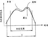
图8A是说明基于电动机的驱动电流判定压接是否正常的方法的曲线图;8A is a graph illustrating a method of determining whether crimping is normal based on a driving current of a motor;
图8B是说明基于压接器高度判定压接是否正常的方法的曲线;8B is a graph illustrating a method of judging whether crimping is normal based on the height of the crimper;
图9是说明现有技术电线接头压接装置的示意图;Fig. 9 is a schematic diagram illustrating a prior art wire connector crimping device;
图10是说明另一个现有技术电线接头压接装置的示意图;和10 is a schematic diagram illustrating another prior art wire splice crimping device; and
图11是示出相应于现有技术的电线接头压接装置在一个接头压接操作中时间和压接器的位置之间的关系的典型曲线图。Fig. 11 is a typical graph showing the relationship between time and the position of the crimper in a terminal crimping operation corresponding to the prior art wire terminal crimping apparatus.
在图1及图2中,标号1表示本发明电线接头压接装置A的外壳,它有一底板2及位于底板2各侧的侧板3,3。在两侧板3,3的后上方设置及固定着一个带有减速齿轮5的伺服电动机4。减速齿轮5有一输出轴6,该轴6轴向连接到带一偏心销8的圆板7。偏心销8是轴向可滑动地与曲柄9的上端部连接,该曲柄9的下端部通过轴向销10与推杆11作可绕枢轴转动的连接。推杆11装成可在设在两侧板3,3内表面上的推杆导向器12,12中上下滑动。圆板7、曲柄9、推杆11和推杆导向器12,12组成活塞-曲柄机构B。In FIGS. 1 and 2,
推杆11的下端有接合的凹部13。该接合的凹部13可脱开地与固定住压接器14的压接器夹具15中的接合凸部16接合。在压接器14的下面,在底板2上固定一个砧17,对着压接器14。标号18是对压接器夹具15导向的导向板18,该导向板18通过托架(未示出)固定在侧板3的内表面。The lower end of the
伺服电动机4可正反转,伺服电动机4通过推杆11垂直地使压接器14作往复运动,推杆11通过活塞-曲柄机构B可绕枢轴转动地与曲柄9连接。另外,伺服电动机4与驱动器34连接以控制伺服电动机的工作。驱动器34与参考数据输入单元22连接,该单元22输入压接器规格(或压接器尺寸),相应的电线尺寸,压接高度(压接器的降低的最低位置)和加在伺服电动机4上的负载(电流)等参考数据。另外,伺服电动机4的输出轴(未示出)上,连接着一个转动编码器33,该编码器33基于转数测出压接器14的位置并把它馈回到读出上述负载电流的驱动器34。The
标号32是测出对接头进行压接时压接器14的高度的高度传感器,该传感器把探测到的高度输到驱动器34以确定接头的压接操作是否正确。此外,标号31是探测伺服电动机4的线圈温度的温度传感器。
图3是操作中控制伺服电动机的驱动器34的功能方框图。如图所示,驱动器34结合成如中央处理单元之类的控制电路,它包括一个数据储存部23,速度控制部24,电流控制部25,判定部26,放大部27,电流探测部28,接口29-1至29-8,和微处理器单元(MPU)30。Figure 3 is a functional block diagram of the
下面,在说明本发明实施例的详细操作前,参照图6和7说明实施例的基本操作。Next, before explaining the detailed operation of the embodiment of the present invention, the basic operation of the embodiment will be described with reference to FIGS. 6 and 7. FIG.
图6A、6B和6C是说明电线接头压接装置的操作的示意图;图7A显示出操作中时间和压接器14的垂直往复运动速度之间的关系的曲线图;图7B是示出同样操作中时间和伺服电动机电流之间的关系的曲线图。另外图7B中的T1、T2和T3分别与图6A、6B和6C相应。6A, 6B and 6C are schematic diagrams illustrating the operation of the wire splice crimping device; FIG. 7A is a graph showing the relationship between time and the vertical reciprocating speed of the crimping
图6A示出电线接头压接操作中的开始阶段,其中,圆板7上的偏心销8处在最高位置,也就是压接器14处在顶部死点。这时,如图7A所示,压接器14的下降速度为零,伺服电动机4的负载电流也为零。Fig. 6A shows the initial stage in the wire splice crimping operation, wherein the
图6B示出开始压接阶段,其中圆板7沿箭头方向转动,偏心销8向下移动;压接器14在与接头C的桶形片C相贴合前以比较大的速度下降。但是在与桶形片C将贴合前,压接器14的下降速度变慢,并且伺服电动机的负载电流减小。Fig. 6B shows the initial crimping stage, in which the
图6C示出压接器14停下来处在进行压接操作,这时在圆板7已沿箭头方向转动使得偏心销8到达底部死点,而压接器14与砧17一起进行压接操作。这时,随着在制动周期t中压接器14已制动,压接器14保持对接头C的桶形片C加压以便继续对抗桶形片C的回弹。因此,负载电流到达最大。在制动阶段的加压消除了桶形片C的回弹而得到高的压接强度。Fig. 6C shows that the crimping
在对接后,伺服电动机4反转,也就是圆板7沿与图6C中箭头的相反方向转动,使得压接器上升到如图6A中的原始状态。After docking, the
在图7A中,在压接的开始阶段,也就是在T2时,压接器14的下降速度比压接器14从顶部位置降到开始压接位置的速度小得多。因此,由于不会产生在一般的飞轮型压接装置中所有的冲击噪音,其减少噪音改善了工作环境。In FIG. 7A, at the beginning of crimping, ie at T2, the descending speed of the
另外,再参见图3,在装置操作前,数据储存部23通过接口29-7从参考数据输入单元22储存用来操作压接装置A的数据用来判定接头是否已正确压接的数据。In addition, referring to FIG. 3 again, before the device is operated, the
用来操作压接装置A的储存数据是伺服电动机在时间T1开始正常转动后伺服电动机加速的速度,在由电动机转动致动的压接器14下降时压接器的下降速度达到均匀速度时压接器14的位置,在时间T2压接器从均匀速度减速时压接器14的位置和减低了的速度,在时间T3压接器的压接开始位置,给定时间t及在给定时间过程中驱动伺服电动机开始反转以升高压接器时伺服电动机的加速的速度,当压接器上升速度达到另一个均匀速度时压接器的位置,压接器从另一个均匀速度减速时压接器14的位置,以及压接器14的停止装置。The stored data used to operate the crimping device A is the speed at which the servo motor accelerates after the servo motor starts normal rotation at time T1, when the descending speed of the
另外,压接器14的位置数据储存相应于与伺服电动机4连接的转动编码器33的输出值。In addition, the position data of the
这些数据分别对要储存的各要压接的接头的尺寸预先通过试验得到。另外,与多种类型的接头相应的数据可以预先存入使得在压接操作中需要时可以读出任何数据。These data are obtained experimentally in advance in each case for the dimensions of the respective crimped joints to be stored. In addition, data corresponding to various types of splices can be stored in advance so that any data can be read out when necessary in a crimping operation.
另外,储存压接器14的位置数据以与转动编码器33的输出值,也就是与圆板7的转动角度相应。因此,即使对于不同的接头类型,可以立即改变压接高度而不用改变现有技术中砧17的高度,当需要时开始压接操作时,压接高度可以方便地精确地调整。In addition, the position data of the
另外,如后面要说明的,判定接头是否已正确压接的数据包括在图7B中示出的电流IU和IL或类似的。在图7B中,I表示某一接头正常地压接在相应尺寸的电线上探测到的电流,IU和IL分别表示测到的电流的上限和下限。IU和IL是基于预先的试验结果测出的。它表示正常的压接时电流I在IU和IL之间。In addition, as will be described later, the data for judging whether or not the terminal has been crimped correctly includes the currents IU and IL shown in FIG. 7B or the like. In FIG. 7B , I represents the current detected when a connector is normally crimped on a wire of corresponding size, and IU and IL represent the upper limit and lower limit of the measured current, respectively. IU and IL were measured based on previous test results. It indicates that the current I is between IU and IL during normal crimping.
另外,参见图4和5,讨论压接器14的操作。图4和5示出驱动器34的操作流程图。Additionally, referring to Figures 4 and 5, the operation of the
在步骤S1,速度控制部24确定开始压接操作的启动信号是否由接口29-8输入。如果判定结果是“否”,则不启动操作一直到判定为“是”时再启动。In step S1, the
在步骤S2,速度控制部24读出数据储存部23发来的对伺服电动机4的正转速度加速,并通过接口29-1把一信号输入到放大部27使得放大部27经伺服电动机4提供一电流,这样伺服电动机4以读出的加速的速度转动。In step S2, the
从转动编码器33通过接口29-4输出的值被差分而得到电动机的转速,进一步,转动速度差分而得到电动机的转动加速。The value output from the
在步骤S3,速度控制部24判定从转动编码器33通过接口29-4输出的值是否与储存在数据储存部23的值相等以及是否相应于开始均匀转速的位置。如果判定结果是“否”,步骤S2继续使电动机加速,如果判定结果是“是”,下一个步骤S4使电动机以均匀速度转动。In step S3, the
另外,在步骤S5,速度控制部24测出已到达电动机的减速开始位置,下面的步骤S2是使电动机转动减速,再下一步骤S7判定压接器是否已到达接头压接位置,如果判定为“是”在步骤S7输出一相应的信号到电流控制部25。In addition, in step S5, the
在电流控制部25,步骤S8读出储存在数据储存部23并为压接阶段伺服电动机要求的电流I。下一个步骤S9基于从温度传感器外通过接口29-4输出的温度值校正电流I使得电动机的力矩等于参考值。另外,下一个步骤S10通过接口29-1输出电流I。In the
在判定部26,步骤S11把判定参考数据记录在一储存器(未示出)中。判定参考数据将在下面详细讨论。In the judging
在电流控制部25,步骤S12判定在时间t伺服电动机4是否已接受电流I,如果判定为“否”则再进行步骤S10及S11。In the
在速度控制部24,步骤S13用预定的加速度使伺服电动机4反转,如果步骤S14判定电动机的转动已达到某一均匀的速度,下一步骤S15保持电动机在均匀速度转动。当下一步骤S16判定压接器到达减速度开始位置,再一步骤S17使电动机减速,在步骤S18基于到达止动位置而使电动机转动停止。In the
在判定部26,步骤S19基于步骤S11记录的数据判定最后的压接操作是否已正常。然后,下一步骤S20在压接监视器21中显示结果,在非正常的压接操作情况下也输出警告信号。In the
为了判定压接操作是否正常,如图8A所示,步骤S11记录在电流探测部28测得的、在正常的时间间隔中供入伺服电动机4中的电流值(驱动电流)。In order to determine whether the crimping operation is normal, as shown in FIG. 8A, step S11 records the current value (drive current) measured at the
图8A示出图7B中在压接操作供到电动机4的驱动电流。电流控制部25进行一个控制使得把标准电流,也就是储存在数据储存部的值,供到电动机。在电动机制动阶段,一个均匀的电流供送到电动机,而在电动机开始转动导致一个修改的控制平衡时电动机驱动电流改变。当接头刚压接时,如果电缆中无芯,或者如果对绝缘线压接,供送的电流比正常压接操作的标准电流更小或更大。因此,在本发明中,压接是否正常基于供到电动机的如此改变的电流来判定。FIG. 8A shows the drive current supplied to the
另外,图8B示出接头压接时高度传感器32的输出。自然,当接头刚压接时,如果电缆无芯或对绝缘线压接,在各时间间隔中输出的最终压接高度变成小于正常压接高度或与该值不同。因此,本发明中,压接是否正常是基于如此改变的压接高度而判定。In addition, FIG. 8B shows the output of the
第一种判定方法(如图8A所示),包括下面步骤:在预定时间读出在步骤S11记录的驱动电流中的最大值;判定该最大值是否在数据储存部23储存的标准值范围内;判定压接是否已基于最大值在标准值范围内而正常地进行。The first judgment method (as shown in Figure 8A) comprises the following steps: read out the maximum value in the driving current recorded in step S11 at a predetermined time; determine whether the maximum value is within the standard value range stored in the
第二种判定方法包括下列步骤:在预定时间把参考电流记在数据储存部23;求出在步骤S11记录的时间顺序电流值与参考电流之间的差;判定压接是否已基于该差值在预定的范围内而正常地进行。The second judging method includes the steps of: recording the reference current in the
第三种判定方法包括下列步骤:在预定的时间求出一定间隔中在步骤S11记录的电流值的总和;判定压接是否基于所述的总和在一个预定的范围内已正常进行。A third judging method includes the steps of: finding the sum of the current values recorded at step S11 at predetermined intervals at a predetermined time; and judging whether crimping has been normally performed within a predetermined range based on said sum.
第四种判定方法(如图8B所示)包括下面步骤:在步骤S11的数据记录中记录从高度传感器32通过接口29与输出的高度值;求出记录数据中的最小值;判定压接是否已基于该最小值在预定的范围内而已经正常进行。The 4th judgment method (as shown in Figure 8B) comprises the following steps: record in the data recording of step S11 from
第五种判定方法包括下列步骤:记录从高度传感器32输出的高度值;求出记录数据中的最小值;比较时间顺序的高度及相应的参考值;判定压接是否已基于上述的差值在一个预定范围而已正常进行。The fifth judgment method includes the following steps: record the height value output from the
另外,监视伺服电动机4中的负载电流I或监视压接器14的高度可确定压接操作是否正常,也就是在压接操作中产品是否无缺陷。另外,在压接操作中设有一止动周期t使得防止接头桶形片回弹,得到可靠的稳定的压接及可靠的产品。In addition, monitoring the load current I in the
在上述压接操作中,用正反转动伺服电动机4来垂直往复移动压接器14,伺服电动机可用液压伺服发动机来代替。In the above-mentioned crimping operation, the
Claims (10)
Applications Claiming Priority (3)
| Application Number | Priority Date | Filing Date | Title |
|---|---|---|---|
| JP328827/1994 | 1994-12-28 | ||
| JP328827/94 | 1994-12-28 | ||
| JP32882794 | 1994-12-28 |
Publications (2)
| Publication Number | Publication Date |
|---|---|
| CN1131833A CN1131833A (en) | 1996-09-25 |
| CN1059986C true CN1059986C (en) | 2000-12-27 |
Family
ID=18214532
Family Applications (1)
| Application Number | Title | Priority Date | Filing Date |
|---|---|---|---|
| CN95121704A Expired - Lifetime CN1059986C (en) | 1994-12-28 | 1995-12-28 | Method of controlling terminal crimping apparatus |
Country Status (5)
| Country | Link |
|---|---|
| US (1) | US5727409A (en) |
| KR (1) | KR100211228B1 (en) |
| CN (1) | CN1059986C (en) |
| DE (1) | DE19548533C2 (en) |
| MX (1) | MX9600168A (en) |
Families Citing this family (32)
| Publication number | Priority date | Publication date | Assignee | Title |
|---|---|---|---|---|
| JPH08279697A (en) * | 1995-04-10 | 1996-10-22 | Fuji Mach Mfg Co Ltd | Electronic component mounting head, electronic component mounting equipment and electronic component mounting method |
| JPH103978A (en) * | 1996-06-12 | 1998-01-06 | Yazaki Corp | Control method of terminal crimping device |
| JPH09330779A (en) * | 1996-06-12 | 1997-12-22 | Yazaki Corp | Control method of terminal crimping device |
| US6035775A (en) * | 1997-02-21 | 2000-03-14 | Novopres Gmbh Pressen Und Presswerkzeuge & Co. Kg | Pressing device having a control device adapted to control the pressing device in accordance with a servocontrol system of the control device |
| EP0884811B1 (en) * | 1997-06-12 | 2003-01-22 | komax Holding AG | Method and machine for making crimp connections |
| DE59806973D1 (en) | 1997-06-12 | 2003-02-27 | Komax Holding Ag Dierikon | Method and device for producing a crimp connection |
| DE19843156A1 (en) * | 1998-09-21 | 2000-04-20 | Sle Electronic Gmbh | Process for quality assurance of crimp connections produced in a crimping device, as well as crimping tool and crimping device |
| US6257042B1 (en) * | 1999-11-05 | 2001-07-10 | Lillbacka Oy | Open throat crimping machine |
| WO2001053016A1 (en) * | 2000-01-17 | 2001-07-26 | Amada Company, Limited | Method of monitoring ram speed of press brake, press brake using the method, and method and apparatus for controlling ram position of press brake |
| US6619088B1 (en) * | 2000-10-16 | 2003-09-16 | Aida Engineering Co., Ltd. | Bottom dead center correction device for servo press machine |
| US6487885B2 (en) * | 2000-10-30 | 2002-12-03 | Komax Holding Ag | Method and apparatus for producing a crimped connection |
| JP4031214B2 (en) * | 2001-03-19 | 2008-01-09 | 矢崎総業株式会社 | Terminal crimping state identification method |
| CN1297044C (en) * | 2001-06-15 | 2007-01-24 | 矢崎总业株式会社 | Detection method for terminal crimping state |
| JP3935034B2 (en) * | 2002-09-17 | 2007-06-20 | 矢崎総業株式会社 | Design support system |
| JP4436053B2 (en) * | 2003-02-13 | 2010-03-24 | 矢崎総業株式会社 | Crimping terminal state estimation device and crimping terminal pass / fail judgment device |
| JP4878490B2 (en) * | 2006-04-07 | 2012-02-15 | 矢崎総業株式会社 | Terminal crimping apparatus and terminal crimping method |
| US7784318B2 (en) * | 2008-03-27 | 2010-08-31 | National Machinery Llc | Turned blank monitor |
| DE102009027967B4 (en) | 2008-08-08 | 2023-06-15 | Volkswagen Ag | Method and device for monitoring the stripping of wire ends |
| JP5164819B2 (en) * | 2008-12-12 | 2013-03-21 | 矢崎総業株式会社 | Crimping method of crimping barrel, crimping barrel and crimping device |
| WO2010116339A1 (en) * | 2009-04-09 | 2010-10-14 | Schleuniger Holding Ag | Method of monitoring a crimping process, crimping press and computer program product |
| US8904616B2 (en) | 2009-04-09 | 2014-12-09 | Schleuniger Holding Ag | Method of monitoring a crimping process, crimping press and computer program product |
| EP2378615A1 (en) * | 2010-04-13 | 2011-10-19 | Schleuniger Holding AG | Crimp press |
| JP5883735B2 (en) * | 2012-07-12 | 2016-03-15 | 矢崎総業株式会社 | Crimp height measurement method and apparatus for crimp terminal, crimp height management method and apparatus |
| TWI608677B (en) | 2012-08-15 | 2017-12-11 | 威查格工具廠有限公司 | Exchanging adapter for a crimp machine |
| JP2014135122A (en) * | 2013-01-08 | 2014-07-24 | Sumitomo Wiring Syst Ltd | Wiring harness processing device |
| BR112015024131A2 (en) | 2013-03-21 | 2017-07-18 | Schleuniger Holding Ag | device for detecting contact of an electrical conductor and removal machine |
| CN103673965B (en) * | 2013-12-25 | 2016-03-30 | 青岛科技大学 | Based on the detection method of the terminal quality detecting system of DSP |
| KR20180079028A (en) * | 2016-12-30 | 2018-07-10 | 주식회사 유라코퍼레이션 | Terminal compressing apparatus and terminal pressing method |
| US10581213B2 (en) * | 2017-04-25 | 2020-03-03 | Te Connectivity Corporation | Crimp tooling having guide surfaces |
| US10566755B2 (en) * | 2017-04-25 | 2020-02-18 | Te Connectivity Corporation | Crimp tooling for terminal crimping machine |
| WO2019152689A2 (en) | 2018-01-31 | 2019-08-08 | Abb Schweiz Ag | Crimping tool with wireless communication system |
| CN113745923A (en) * | 2021-08-25 | 2021-12-03 | 深圳市速联技术有限公司 | High-precision tool process for preventing backward compression joint and preventing fool through bidirectional positioning |
Citations (1)
| Publication number | Priority date | Publication date | Assignee | Title |
|---|---|---|---|---|
| US5115735A (en) * | 1989-06-23 | 1992-05-26 | Amp Incorporated | Press with control circuit arrangement |
Family Cites Families (18)
| Publication number | Priority date | Publication date | Assignee | Title |
|---|---|---|---|---|
| DE3788349T2 (en) * | 1986-12-29 | 1994-05-11 | Mitoshi Ishii | POWER STEERING DEVICE FOR A PRESS. |
| DE3842009C1 (en) * | 1988-11-22 | 1990-03-22 | Kabelwerke Reinshagen Gmbh, 5600 Wuppertal, De | |
| DE4014221A1 (en) * | 1989-05-12 | 1990-11-15 | Siemens Ag | METHOD AND DEVICE FOR PRODUCTION MONITORING IN CRIMPING FLEXIBLE, STRIPED CORES OF CABLES |
| US4916810A (en) * | 1989-05-12 | 1990-04-17 | Amp Incorporated | Method and apparatus for terminating wires to terminals |
| US5129317A (en) * | 1989-06-23 | 1992-07-14 | Amp Incorporated | Press driven by an electric motor through reduction gearing |
| GB8927467D0 (en) * | 1989-12-05 | 1990-02-07 | Amp Gmbh | Crimped connection quality control |
| GB8927466D0 (en) * | 1989-12-05 | 1990-02-07 | Amp Gmbh | Electrical terminal crimping apparatus |
| US5271254A (en) * | 1989-12-05 | 1993-12-21 | The Whitaker Corporation | Crimped connector quality control method apparatus |
| DE4040410C1 (en) * | 1989-12-21 | 1991-11-07 | Bernhard Dr.-Ing. 4782 Erwitte De Juergenhake | Tooling for crimping electrical connectors - comprises crank press with spring-loaded plunger, connected torsionally to transducer providing displacement measurement |
| DE3942219C1 (en) * | 1989-12-21 | 1991-02-21 | Bernhard Dr.-Ing. 4782 Erwitte De Juergenhake | Crimped connection quality measurement method - measuring distance positionally fixed tool or press base and active tool or press head |
| US5197186A (en) * | 1990-05-29 | 1993-03-30 | Amp Incorporated | Method of determining the quality of a crimped electrical connection |
| GB9012058D0 (en) * | 1990-05-30 | 1990-07-18 | Amp Gmbh | Method of,and apparatus for,controlling the crimp height of crimped electrical connections |
| US5113679A (en) * | 1990-06-27 | 1992-05-19 | Burndy Corporation | Apparatus for crimping articles |
| DE9014442U1 (en) * | 1990-10-18 | 1991-09-12 | AAT Aston GmbH Geräte für Elektronikfertigung und Kabelbearbeitung, 8500 Nürnberg | Device for measuring the force when crimping cable lugs (crimping force) |
| JPH0529056A (en) * | 1991-07-18 | 1993-02-05 | Nippon Autom Mach Kk | Terminal crimping automatic adjustment device |
| JPH0625911Y2 (en) * | 1991-07-18 | 1994-07-06 | 日本オートマチックマシン株式会社 | Wire terminal crimping device |
| JPH0529055A (en) * | 1991-07-18 | 1993-02-05 | Nippon Autom Mach Kk | Terminal crimp automatic adjustment device |
| DE4215163C2 (en) * | 1992-05-08 | 1995-01-05 | Grote & Hartmann | Crimp monitoring method for crimp fault detection and device for carrying out the method |
-
1995
- 1995-12-21 US US08/576,019 patent/US5727409A/en not_active Expired - Lifetime
- 1995-12-22 DE DE19548533A patent/DE19548533C2/en not_active Expired - Lifetime
- 1995-12-28 CN CN95121704A patent/CN1059986C/en not_active Expired - Lifetime
- 1995-12-28 KR KR1019950061340A patent/KR100211228B1/en not_active Expired - Lifetime
-
1996
- 1996-01-09 MX MX9600168A patent/MX9600168A/en unknown
Patent Citations (1)
| Publication number | Priority date | Publication date | Assignee | Title |
|---|---|---|---|---|
| US5115735A (en) * | 1989-06-23 | 1992-05-26 | Amp Incorporated | Press with control circuit arrangement |
Also Published As
| Publication number | Publication date |
|---|---|
| US5727409A (en) | 1998-03-17 |
| CN1131833A (en) | 1996-09-25 |
| KR960021252A (en) | 1996-07-18 |
| MX9600168A (en) | 1997-01-31 |
| KR100211228B1 (en) | 1999-07-15 |
| DE19548533A1 (en) | 1996-07-11 |
| DE19548533C2 (en) | 2000-09-07 |
Similar Documents
| Publication | Publication Date | Title |
|---|---|---|
| CN1059986C (en) | Method of controlling terminal crimping apparatus | |
| CN1060886C (en) | Method of crimping terminal and apparatus for the same | |
| CN1041475C (en) | device for crimping connectors onto wires | |
| US4916810A (en) | Method and apparatus for terminating wires to terminals | |
| US5887469A (en) | Terminal crimping device | |
| CN1190122C (en) | Component mounting apparatus and device for detecting attachment of component on substrate | |
| CN1056959A (en) | Determine the method for the electrical connection quality of crimping | |
| JP3156841B2 (en) | Control method of terminal crimping device | |
| JPH09330779A (en) | Control method of terminal crimping device | |
| CN1284906A (en) | A placement device for a mechanical holding mechanism | |
| JPH103978A (en) | Control method of terminal crimping device | |
| CN101227055A (en) | Method for measuring metal terminals and device for measuring metal terminals | |
| JPH08236253A (en) | Control method of terminal crimping device | |
| JPH08236251A (en) | Terminal crimping method and device | |
| JPH11273823A (en) | Crimp failure detection method for terminal crimping equipment | |
| JP2001035628A (en) | Terminal crimping state determination method and device | |
| CN218525972U (en) | Wiring device and mobile terminal assembly system | |
| JP3107147B2 (en) | Terminal crimping method and equipment | |
| JPH06223951A (en) | Quality control device for crimp terminal | |
| JP3626722B2 (en) | Terminal crimping type and terminal crimping machine having the same | |
| CN108956155B (en) | Detection device | |
| JPH0625911Y2 (en) | Wire terminal crimping device | |
| CN223557296U (en) | Intelligent machining equipment for twist drills | |
| CN209979113U (en) | Torsion detection equipment | |
| JP3280333B2 (en) | Terminal crimping device |
Legal Events
| Date | Code | Title | Description |
|---|---|---|---|
| C06 | Publication | ||
| PB01 | Publication | ||
| C10 | Entry into substantive examination | ||
| SE01 | Entry into force of request for substantive examination | ||
| C14 | Grant of patent or utility model | ||
| GR01 | Patent grant | ||
| CX01 | Expiry of patent term |
Granted publication date: 20001227 |
|
| EXPY | Termination of patent right or utility model |