CN106347340B - Distribution valve for controlling conversion between inflation relief position and braking position of volume chamber - Google Patents
Distribution valve for controlling conversion between inflation relief position and braking position of volume chamber Download PDFInfo
- Publication number
- CN106347340B CN106347340B CN201611006208.XA CN201611006208A CN106347340B CN 106347340 B CN106347340 B CN 106347340B CN 201611006208 A CN201611006208 A CN 201611006208A CN 106347340 B CN106347340 B CN 106347340B
- Authority
- CN
- China
- Prior art keywords
- volume chamber
- inflation
- sleeve
- passage
- valve
- Prior art date
- Legal status (The legal status is an assumption and is not a legal conclusion. Google has not performed a legal analysis and makes no representation as to the accuracy of the status listed.)
- Active
Links
- 238000009826 distribution Methods 0.000 title claims description 14
- 238000006243 chemical reaction Methods 0.000 title abstract description 6
- 238000007789 sealing Methods 0.000 claims abstract description 27
- 238000000034 method Methods 0.000 claims description 6
- 230000008569 process Effects 0.000 claims description 6
- 239000002184 metal Substances 0.000 abstract description 3
- 230000006837 decompression Effects 0.000 description 6
- 239000003292 glue Substances 0.000 description 5
- 230000001603 reducing effect Effects 0.000 description 4
- 230000009471 action Effects 0.000 description 3
- 230000000694 effects Effects 0.000 description 2
- 230000003137 locomotive effect Effects 0.000 description 2
- 230000009467 reduction Effects 0.000 description 2
- 239000003381 stabilizer Substances 0.000 description 2
- 238000012546 transfer Methods 0.000 description 2
- 230000008859 change Effects 0.000 description 1
- 238000004891 communication Methods 0.000 description 1
- 230000001419 dependent effect Effects 0.000 description 1
- 230000005484 gravity Effects 0.000 description 1
- 238000012423 maintenance Methods 0.000 description 1
- 238000004519 manufacturing process Methods 0.000 description 1
- 230000007246 mechanism Effects 0.000 description 1
- 238000012986 modification Methods 0.000 description 1
- 230000004048 modification Effects 0.000 description 1
- 238000002360 preparation method Methods 0.000 description 1
- 230000007704 transition Effects 0.000 description 1
Images


Classifications
-
- B—PERFORMING OPERATIONS; TRANSPORTING
- B60—VEHICLES IN GENERAL
- B60T—VEHICLE BRAKE CONTROL SYSTEMS OR PARTS THEREOF; BRAKE CONTROL SYSTEMS OR PARTS THEREOF, IN GENERAL; ARRANGEMENT OF BRAKING ELEMENTS ON VEHICLES IN GENERAL; PORTABLE DEVICES FOR PREVENTING UNWANTED MOVEMENT OF VEHICLES; VEHICLE MODIFICATIONS TO FACILITATE COOLING OF BRAKES
- B60T15/00—Construction arrangement, or operation of valves incorporated in power brake systems and not covered by groups B60T11/00 or B60T13/00
- B60T15/02—Application and release valves
-
- B—PERFORMING OPERATIONS; TRANSPORTING
- B61—RAILWAYS
- B61H—BRAKES OR OTHER RETARDING DEVICES SPECIALLY ADAPTED FOR RAIL VEHICLES; ARRANGEMENT OR DISPOSITION THEREOF IN RAIL VEHICLES
- B61H11/00—Applications or arrangements of braking or retarding apparatus not otherwise provided for; Combinations of apparatus of different kinds or types
- B61H11/06—Applications or arrangements of braking or retarding apparatus not otherwise provided for; Combinations of apparatus of different kinds or types of hydrostatic, hydrodynamic, or aerodynamic brakes
Landscapes
- Engineering & Computer Science (AREA)
- Mechanical Engineering (AREA)
- Physics & Mathematics (AREA)
- Fluid Mechanics (AREA)
- Transportation (AREA)
- Transmission Of Braking Force In Braking Systems (AREA)
- Actuator (AREA)
Abstract
The utility model discloses a distributing valve for controlling the conversion between a volume chamber inflation relief position and a braking position, which comprises a valve body composition, wherein a main valve sleeve and a main control sleeve sleeved in the main valve sleeve are arranged in the valve body composition, the main valve sleeve is fixedly connected with the valve body composition, the main control sleeve moves up and down relative to the main valve sleeve under the control of a piston rod in the valve body composition, and a volume chamber exhaust passage R1p and a volume chamber inflation passage R1c which are respectively communicated with a volume chamber R1 are arranged on the main valve sleeve. The utility model divides the volume chamber passage into two parts, the main valve sleeve is respectively provided with the volume chamber exhaust passage and the volume chamber inflation passage which are communicated with the volume chamber, and the corresponding passages are separated, divided and communicated through the rubber sealing rings arranged between the cylindrical main valve sleeve and the main control sleeve, so that the metal plane sealing junctions of the original slide valve, the throttle valve and the slide valve seat are replaced, the opening, closing and sealing of the passages are realized, and the inflation and the exhaust of the volume chamber are orderly controllable without disorder.
Description
Technical Field
The utility model belongs to the technical field of air brake distribution valves for rail transit locomotives and particularly relates to a distribution valve for controlling the conversion of a volume chamber inflation relief position and a brake position.
Background
At present, main control mechanisms in an air brake distribution valve for rail transit locomotives are a slide valve, a throttle valve and a slide valve seat, and the slide valve, the throttle valve and the slide valve seat are relatively moved, and the slide valve, the throttle valve and the slide valve seat are mutually communicated by utilizing a metal plane sealing structure, so that the functions of braking, relieving, pressure maintaining and the like of the distribution valve are realized.
In the structure of the existing distribution valve, the conversion between the inflation relief position and the braking position of the volume chamber is realized by corresponding communication of one passage arranged on the slide valve seat and the inflation and exhaust passages arranged on the slide valve respectively.
Disclosure of Invention
The utility model aims at: aiming at the problems, the distribution valve for controlling the switching between the inflation release position and the braking position of the volume chamber can enable the inflation and the exhaust of the volume chamber to be orderly and controllable and can operate stably and reliably.
The technical scheme of the utility model is realized as follows: a distributing valve for controlling the transition between the inflation relief position and the braking position of a volume chamber comprises a valve body and is characterized in that: the valve body is internally provided with a main valve sleeve and a main control sleeve sleeved in the main valve sleeve, the main valve sleeve is fixedly connected with the valve body, the main control sleeve moves up and down relative to the main valve sleeve under the control of an inner piston rod in the valve body, the main valve sleeve is provided with a volume chamber exhaust passage R1p and a volume chamber inflation passage R1c which are respectively communicated with a volume chamber R1, the volume chamber exhaust passage R1p is communicated with the exhaust passage D1 on the main valve sleeve through a volume chamber exhaust ring groove D2 arranged on the main control sleeve, the volume chamber inflation passage R1c is communicated with one end of an inflation passage G3 in the main control sleeve through a volume chamber inflation ring groove G4 arranged on the main control sleeve, the other end of the inflation passage G3 is communicated with the inner passage of the piston rod, the inner passage of the piston rod is communicated with a working air cylinder, a lower chamber G1 formed by the piston in the valve body is communicated with the main valve, a rubber sealing ring is arranged between the main valve sleeve and the main valve sleeve, the rubber sealing ring is respectively arranged above the volume chamber exhaust ring groove D2, below the volume chamber G4 and the main valve sleeve are respectively communicated with the main control sleeve, and the volume chamber R1 is opened when the volume chamber G1 is opened and the volume chamber R1 is closed by the ring groove R1.
According to the distribution valve for controlling the conversion between the inflation release position and the braking position of the volume chamber, in the process of switching from the inflation release position to the braking position, the corresponding rubber sealing ring on the main control sleeve firstly closes the volume chamber exhaust passage R1p, and then opens the volume chamber inflation passage R1c through the corresponding rubber sealing ring; in the process of switching from the braking position to the inflation release position, the corresponding rubber sealing ring on the main control sleeve firstly closes the volume chamber inflation passage R1c, and then opens the volume chamber exhaust passage R1p through the corresponding rubber sealing ring.
The utility model divides the passage of the volume chamber into two parts, the main valve sleeve is respectively provided with the exhaust passage of the volume chamber and the inflating passage of the volume chamber, and the corresponding passages are separated, divided and communicated by the rubber sealing rings arranged between the cylindrical main valve sleeve and the main control sleeve, thereby replacing the metal plane sealing junctions of the original slide valve, the throttle valve and the slide valve seat, realizing the on-off and sealing of the passages, ensuring that the inflating and the exhausting of the volume chamber are orderly controllable without disorder, greatly improving the action reliability of the distributing valve, effectively prolonging the maintenance period of the distributing valve, having simple manufacturing process, low requirement on the skill of operators and small labor intensity.
Drawings
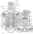
FIG. 1 is a schematic view of the present utility model in a gas filled alleviating position.
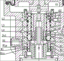
Fig. 2 is an enlarged view of the interior of the valve body assembly of fig. 1.
Fig. 3 is a schematic view of the present utility model in a braking position.
Fig. 4 is an enlarged view of the interior of the valve body assembly of fig. 3.
The marks in the figure: 1 is a valve body composition, 2 is a main valve sleeve, 3 is a main control sleeve, 4 is a piston rod, 4a is an internal passage of the piston rod, 5 is a piston composition, 6 is a rubber sealing ring, 7 is a main control inner sleeve, 8 is a stabilizer bar, and 9 is a transfer sleeve.
Detailed Description
The present utility model will be described in detail with reference to the accompanying drawings.
The present utility model will be described in further detail with reference to the drawings and examples, in order to make the objects, technical solutions and advantages of the present utility model more apparent. It should be understood that the specific embodiments described herein are for purposes of illustration only and are not intended to limit the scope of the utility model.
As shown in figures 1-4, the distribution valve for controlling the change of the inflation relief position and the braking position of the volume chamber comprises a valve body assembly 1, wherein a main valve sleeve 2 and a main control sleeve 3 sleeved in the main valve sleeve 2 are arranged in the valve body assembly 1, the main valve sleeve 2 is fixedly connected with the valve body assembly 1, the main control sleeve 3 moves up and down relative to the main valve sleeve 2 under the control of a piston rod 4 in the valve body assembly 1, a volume chamber exhaust passage R1p and a volume chamber inflation passage R1c which are respectively communicated with the volume chamber R1 are arranged on the main valve sleeve 2, the volume chamber exhaust passage R1p is communicated with an exhaust passage D1 on the main valve sleeve 2 through a volume chamber exhaust ring groove D2 arranged on the main control sleeve 3, the volume chamber inflation passage R1c is communicated with one end of an inflation passage G3 in the main control sleeve 3 through a volume chamber inflation ring groove G4 arranged on the main control sleeve 3, the other end of the inflation passage G3 is communicated with an inner passage 4a of the piston rod 4, the inner passage 4a of the piston rod 4 is communicated with a lower chamber G1 of a piston assembly 5 in the valve body assembly 1, the lower chamber G1 of the piston assembly 5 is communicated with a working air cylinder, a rubber sealing ring 6 is arranged between the main valve sleeve 2 and the main control sleeve 3, the rubber sealing ring 6 is respectively arranged above the volume chamber exhaust ring groove D2, below the volume chamber inflation ring groove G4 and between the volume chamber exhaust ring groove D2 and the volume chamber inflation ring groove G4, and through the up-and-down movement of the main control sleeve 3, when the distribution valve is in an inflation relief position, the volume chamber exhaust passage R1p is opened and the volume chamber inflation passage R1c is closed, and when the distribution valve is in a braking position, the volume chamber exhaust passage R1c is opened and the volume chamber exhaust passage R1p is closed.
In the process of switching from the inflation release position to the braking position, the corresponding rubber sealing ring 6 on the main control sleeve 3 firstly closes the volume chamber exhaust passage R1p, and then opens the volume chamber inflation passage R1c through the corresponding rubber sealing ring 6; in the process of switching from the braking position to the inflation release position, the corresponding rubber sealing ring 6 on the main control sleeve 3 firstly closes the volume chamber inflation passage R1c, and then opens the volume chamber exhaust passage R1p through the corresponding rubber sealing ring 6.
The working principle of the utility model is as follows:
as shown in fig. 1 and 2, the present utility model is schematically illustrated in the inflation relief position.
a. And (5) primary inflation.
When the train pipe is inflated, the pressure air reaches the distributing valve through the train pipe, the branch pipe and the like, then one path of pressure air reaches the upper cavity of the piston assembly 5 through the passage L1, the piston assembly 5 moves downwards, the piston assembly 5 drives the main control inner sleeve 7 through the piston rod 4 and simultaneously pushes the main control sleeve 3 to move downwards through the upper shoulder of the piston rod 4 until the lower end of the piston assembly 5 contacts the main valve body. At this time, the piston assembly 5, the piston rod 4, the main control inner sleeve 7 and the main control sleeve 3 are in the inflation relief position. The pressure air of the train pipe is respectively inflated to the working air cylinder, the auxiliary air cylinder and other air cylinders (chambers) through different passages, so that the working air cylinder, the auxiliary air cylinder and other air cylinders (chambers) are inflated to constant pressure (such as 500kPa or 600 kPa) for decelerating or stopping the train during running.
And (3) inflating the working air cylinder: train pipe pressure air- & gt L2- & gt a main valve sleeve corresponding passage- & gt a main control sleeve L8- & gt a main control sleeve G2- & gt a lower chamber G1 formed by pistons- & gt a working air cylinder.
And (5) inflating the auxiliary air cylinder: train pipe pressure air- & gt inflation part (controlled by working reservoir) & gt auxiliary reservoir.
The upper side F2 of the relay glue-pouring valve of the relay part is always communicated with the auxiliary air cylinder, and the pressure air of the auxiliary air cylinder waits on the upper side of the relay glue-pouring valve, so that preparation is made for the next braking action.
The train pipe pressure air- & gt L4- & gt the main valve sleeve corresponding passage- & gt the main control sleeve L5- & gt the main control sleeve L6 are prepared for the partial decompression in the first stage when the next braking is performed.
b. Re-inflation and relief.
After the train pipe is decompressed to brake the train, when the train pipe is inflated again, the pressure balance state of the two sides of the piston assembly 5 is destroyed when the brake is maintained due to the pressurization of the train pipe, and when the sum of the downward acting force generated by the pressure difference of the two sides of the piston assembly 5 and the gravity of the piston assembly 5 exceeds the friction resistance between the rubber sealing ring on the main control sleeve and the main control sleeve, the piston assembly 5 drives the main control sleeve and the main control sleeve to move downwards to an inflation relief position together. At this time, the working reservoir, the auxiliary reservoir and other reservoirs (chambers) are recharged, the volume chambers and the brake cylinders are exhausted (relieved), and the brake is in a relieved state.
All the passages mentioned above for "initial inflation" are also present for re-inflation.
Volume chamber relief: volume chamber pressure air- & gtR1- & gtMain valve sleeve R1p- & gtMain control sleeve D2- & gtD1- & gtatmosphere.
The relay part relays the pressure air of the lower cavity of the piston, R3, the internal passage of the valve body, the volume chamber, R1, the main valve sleeve R1p, the main control sleeve D2, D1 and the atmosphere.
Since this valve is a two-pressure-mechanism valve, the volume chambers together with the pressure air of the lower chamber of the relay piston are exhausted once, and their pressure drops to zero.
Brake cylinder relief: the upper cavity Z3 of the relay piston is communicated with the brake cylinder, and the lower cavity R3 is communicated with the volume chamber. Because the volume chambers are relieved, the original pressure balance state at the two sides of the relay piston is destroyed, the pressure of the brake cylinder enables the relay piston to move downwards, the upper end of the relay piston rod leaves the relay glue filling valve, and then the pressure air of the brake cylinder, the internal channel of the valve body, Z1, the relay piston rod D4, D3 and the atmosphere are all the same. The brake cylinder pressure is vented to atmosphere and the brake is brought into a state of alleviation. Meanwhile, the pressure air in the upper cavity Z3 of the relay piston passes through the shrinkage cavity C2 and the pressure air in the upper cavity Z2 of the relay glue filling valve together with the pressure air in the upper cavity Z2 of the relay piston and passes through the Z1-relay piston rod D4-D3-atmosphere.
It follows that the brake cylinder pressure is controlled by the volume chamber pressure. Since the pressure of the volume chamber is relieved to zero at one time, the pressure of the brake cylinder is correspondingly relieved to zero at one time, and the brake is completely relieved.
As shown in fig. 3 and 4, the present utility model is schematically illustrated in a braking position.
After partial decompression in the first stage, the pressure difference at two sides of the piston assembly 5 is promoted to be increased rapidly, and then the piston assembly 5 pushes the main control sleeve to overcome the friction resistance with the main control sleeve through the piston rod 4, the stabilizer rod 8 and the transfer sleeve 9, and further moves upwards to a braking position. Because the relative positions of the main control sleeve 3 and the main control sleeve 2 are changed, the Ju2 holes and the Ju1 holes on the main control sleeve 3 are staggered, so that the passage between the train pipe and the partial decompression chamber is cut off, and the partial decompression effect in the first stage is finished. Meanwhile, some holes on the main control sleeve 3 are respectively communicated with corresponding holes on the main control sleeve 2, so that the following passages are formed, and a braking effect is further generated.
a. Train pipe pressure air- & gt L4- & gt a main valve sleeve corresponding passage- & gt a main control sleeve L5- & gt a main control sleeve L3- & gt a hidden channel in a valve body- & gt a local limiting valve (opening state- & gt a brake cylinder. In this way, each vehicle is caused to introduce a portion of the train line pressure air through the valve of the host vehicle into the brake cylinder via the open partial pressure reducing restriction valve, which is the second stage partial pressure reducing action.
When the brake cylinder pressure increases to 50-70 kPa, the local pressure reducing limiting valve is closed, the passage is shut off, and the second-stage local pressure reducing action is stopped. The second stage of local decompression stopping can ensure that the train at the tail of the train has a certain braking force even if the train pipe is small in decompression amount.
b. The volume chamber is inflated: working reservoir pressure air- →g1- →g3- →g4- →r1c- →r1- →volume chamber.
c. And (3) inflating a brake cylinder: the volume chamber is always communicated with the lower cavity of the relay piston, so that the volume chamber is pressurized air, a channel inside the valve body, R3, the relay piston and the relay piston rod are pushed to move upwards, and the relay piston rod pushes up the relay glue filling valve.
Auxiliary air cylinder pressure air- & gt F2- & gt a jacking relay glue filling valve- & gt Z1- & gt a blind channel in a valve body and a brake cylinder. Thus, the brake cylinder pressure continues to increase. Meanwhile, one path of air under pressure of the brake cylinder enters the upper side Z2 of the relay glue filling valve, and the other path of air under pressure is contracted and blocked C2 to enter the upper cavity of the relay piston. The action of the shrinkage plug C2 synchronizes the boosting of the upper cavity of the relay piston with the boosting of the brake cylinder.
Since the second stage partial pressure reduction takes place substantially simultaneously with the inflation of the working reservoir into the volume chamber, i.e. immediately after the pressure air of the train pipe has entered the brake cylinder, the pressure air of the auxiliary reservoir also starts to enter the brake cylinder, so that the initial pressure of the brake cylinder is 50-70 kPa from both the train pipe and the auxiliary reservoir, and after this pressure is reached the partial pressure limiting valve is closed, whereupon the train pipe stops inflating the brake cylinder, only the auxiliary reservoir inflates the brake cylinder, as far as the brake cylinder continues to inflate, up to a pressure which is also dependent on the magnitude of the pressure reduction of the train pipe operated by the driver.
The foregoing description of the preferred embodiments of the utility model is not intended to be limiting, but rather is intended to cover all modifications, equivalents, and alternatives falling within the spirit and principles of the utility model.
Claims (1)
1. A dispensing valve for controlling the switching between a filling relief position and a braking position of a volume chamber, comprising a valve body (1), characterized in that: a main valve sleeve (2) and a main control sleeve (3) sleeved in the main valve sleeve (2) are arranged in the valve body component (1), the main valve sleeve (2) is fixedly connected with the valve body component (1), the main control sleeve (3) moves up and down relative to the main valve sleeve (2) under the control of a piston rod (4) in the valve body component (1), a volume chamber exhaust passage (R1 p) and a volume chamber inflation passage (R1 c) which are respectively communicated with a volume chamber (R1) are arranged on the main valve sleeve (2), the volume chamber exhaust passage (R1 p) is communicated with an exhaust passage (D1) in the main valve sleeve (2) through a volume chamber exhaust ring groove (D2) arranged on the main control sleeve (3), the volume chamber inflation passage (R1 c) is communicated with one end of an inflation passage (G3) in the main control sleeve (3) through a volume chamber inflation ring groove (G4) arranged on the main control sleeve (3), the other end of the inflation passage (G3) is communicated with an internal passage (4 a) of the piston rod (4), the internal passage (4 a) is communicated with a working chamber (5) in the piston cylinder (1) and the lower chamber (5) is communicated with the piston rod (1), a rubber sealing ring (6) is arranged between the main valve sleeve (2) and the main control sleeve (3), the rubber sealing ring (6) is respectively arranged above the volume chamber exhaust ring groove (D2), below the volume chamber inflation ring groove (G4) and between the volume chamber exhaust ring groove (D2) and the volume chamber inflation ring groove (G4), when the distribution valve is in an inflation relief position, the volume chamber exhaust passage (R1 p) is opened and the volume chamber inflation passage (R1 c) is closed through the up-down movement of the main control sleeve (3), and when the distribution valve is in a braking position, the volume chamber inflation passage (R1 c) is opened and the volume chamber exhaust passage (R1 p) is closed;
in the process of switching from the inflation release position to the braking position, the corresponding rubber sealing ring (6) on the main control sleeve (3) firstly closes the volume chamber exhaust passage (R1 p), and then opens the volume chamber inflation passage (R1 c) through the corresponding rubber sealing ring (6); in the process of switching from a braking position to an inflation relief position, the corresponding rubber sealing ring (6) on the main control sleeve (3) firstly closes the volume chamber inflation passage (R1 c), and then opens the volume chamber exhaust passage (R1 p) through the corresponding rubber sealing ring (6).
Priority Applications (1)
| Application Number | Priority Date | Filing Date | Title |
|---|---|---|---|
| CN201611006208.XA CN106347340B (en) | 2016-11-16 | 2016-11-16 | Distribution valve for controlling conversion between inflation relief position and braking position of volume chamber |
Applications Claiming Priority (1)
| Application Number | Priority Date | Filing Date | Title |
|---|---|---|---|
| CN201611006208.XA CN106347340B (en) | 2016-11-16 | 2016-11-16 | Distribution valve for controlling conversion between inflation relief position and braking position of volume chamber |
Publications (2)
| Publication Number | Publication Date |
|---|---|
| CN106347340A CN106347340A (en) | 2017-01-25 |
| CN106347340B true CN106347340B (en) | 2023-04-28 |
Family
ID=57862528
Family Applications (1)
| Application Number | Title | Priority Date | Filing Date |
|---|---|---|---|
| CN201611006208.XA Active CN106347340B (en) | 2016-11-16 | 2016-11-16 | Distribution valve for controlling conversion between inflation relief position and braking position of volume chamber |
Country Status (1)
| Country | Link |
|---|---|
| CN (1) | CN106347340B (en) |
Families Citing this family (1)
| Publication number | Priority date | Publication date | Assignee | Title |
|---|---|---|---|---|
| CN114834420B (en) * | 2022-05-13 | 2023-04-25 | 中车齐齐哈尔车辆有限公司 | Accelerating brake valve and air control valve with same |
Citations (2)
| Publication number | Priority date | Publication date | Assignee | Title |
|---|---|---|---|---|
| CN105313917A (en) * | 2014-07-28 | 2016-02-10 | 青岛四方车辆研究所有限公司 | Double-diaphragm-plate relay valve for high-speed EMU (electric multiple unit) and urban rail vehicle |
| CN205086904U (en) * | 2015-10-12 | 2016-03-16 | 四川制动科技股份有限公司 | Plunger type three -way valve |
Family Cites Families (15)
| Publication number | Priority date | Publication date | Assignee | Title |
|---|---|---|---|---|
| ES389901A1 (en) * | 1971-04-03 | 1974-06-16 | Franco Otegui | Improvements in main braking pump of double circuit, and producer of different and proportional pressures. (Machine-translation by Google Translate, not legally binding) |
| US4339155A (en) * | 1980-10-08 | 1982-07-13 | American Standard Inc. | Control valve arrangement for combined brake and air reservoir device |
| RU2296070C1 (en) * | 2005-11-29 | 2007-03-27 | Открытое акционерное общество МТЗ ТРАНСМАШ | Rail vehicle brake air distributor |
| US7658453B2 (en) * | 2006-02-16 | 2010-02-09 | Meritor Wabco Vehicle Control Systems | Service brake relay with integrated quick release valve |
| DE102008060912B4 (en) * | 2008-12-06 | 2013-11-21 | Haldex Brake Products Gmbh | Pneumatic brake system with a parking valve |
| CN201544951U (en) * | 2009-11-09 | 2010-08-11 | 天津机辆轨道交通装备有限责任公司 | Relay valve |
| CN102167026B (en) * | 2011-04-07 | 2013-01-09 | 北京南车时代机车车辆机械有限公司 | Electric control dual-chamber relay valve |
| CN102923118B (en) * | 2012-11-22 | 2016-06-01 | 四川制动科技股份有限公司 | A kind of locomotive distribution valve and method of work thereof |
| CN202987124U (en) * | 2012-11-22 | 2013-06-12 | 四川制动科技股份有限公司 | Locomotive distributing valve |
| CN104192122A (en) * | 2014-08-26 | 2014-12-10 | 王勤黄 | Anti-failure quadruple-control master brake valve |
| CN104309602B (en) * | 2014-10-16 | 2016-08-24 | 眉山中车制动科技股份有限公司 | A kind of relay valve with empty and load brake-cylinder pressure adjustment function |
| CN105151034B (en) * | 2015-10-12 | 2017-09-15 | 眉山中车制动科技股份有限公司 | A kind of plunger type triple valve |
| CN205202996U (en) * | 2015-10-30 | 2016-05-04 | 四川制动科技股份有限公司 | Bivalve mouth formula electric pneumatic valve |
| CN106043268B (en) * | 2016-06-30 | 2018-07-24 | 眉山中车制动科技股份有限公司 | A kind of double-heading valve with auto-conversion function |
| CN206141528U (en) * | 2016-11-16 | 2017-05-03 | 眉山中车制动科技股份有限公司 | A distribution valve for controlling volume room is aerifyd and is alleviated position and braking position conversion |
-
2016
- 2016-11-16 CN CN201611006208.XA patent/CN106347340B/en active Active
Patent Citations (2)
| Publication number | Priority date | Publication date | Assignee | Title |
|---|---|---|---|---|
| CN105313917A (en) * | 2014-07-28 | 2016-02-10 | 青岛四方车辆研究所有限公司 | Double-diaphragm-plate relay valve for high-speed EMU (electric multiple unit) and urban rail vehicle |
| CN205086904U (en) * | 2015-10-12 | 2016-03-16 | 四川制动科技股份有限公司 | Plunger type three -way valve |
Also Published As
| Publication number | Publication date |
|---|---|
| CN106347340A (en) | 2017-01-25 |
Similar Documents
| Publication | Publication Date | Title |
|---|---|---|
| CN107097770B (en) | Air brake valve for railway carriage | |
| CN104309602B (en) | A kind of relay valve with empty and load brake-cylinder pressure adjustment function | |
| CN106347341B (en) | Main control mechanism for keeping pressure of brake pressure maintaining position of distribution valve stable | |
| CN113525326B (en) | Three-pressure distribution valve | |
| CN102923118A (en) | Locomotive distribution valve and working method thereof | |
| CN102114854A (en) | Distribution valve for brake system of high-speed train | |
| CN202481072U (en) | Relay valve used for rail traffic vehicle through electric pneumatic braking system | |
| CN106347340B (en) | Distribution valve for controlling conversion between inflation relief position and braking position of volume chamber | |
| CN206826636U (en) | A kind of passenger train air brake valve | |
| CN204136976U (en) | A kind of relay valve with empty and load brake-cylinder pressure adjustment function | |
| CN204161350U (en) | A kind of anti-malfunctioning vehicle air brake system | |
| AU2017229218B2 (en) | Brake cylinder maintaining valve | |
| CN105151034A (en) | Plunger type three-way valve | |
| CN106627542B (en) | Multi-channel rubber cylinder sealing distribution valve | |
| CN105365805A (en) | Pneumatic braking system capable of preventing vehicle from having malfunctions | |
| CN206141528U (en) | A distribution valve for controlling volume room is aerifyd and is alleviated position and braking position conversion | |
| CN112361049A (en) | Pressure regulating valve of railway wagon | |
| CN114834420B (en) | Accelerating brake valve and air control valve with same | |
| CN103359102A (en) | Trailer valve with throttling function | |
| CN115214585B (en) | Air control valve | |
| CN114802160B (en) | Air control valve with acceleration relieving function | |
| CN206202278U (en) | A kind of multi-path rubber cylinder seals distributing valve | |
| CN104192123A (en) | Intelligent air cut valve | |
| CN205086904U (en) | Plunger type three -way valve | |
| CN104405712A (en) | Passenger and freight change-over valve |
Legal Events
| Date | Code | Title | Description |
|---|---|---|---|
| C06 | Publication | ||
| PB01 | Publication | ||
| SE01 | Entry into force of request for substantive examination | ||
| SE01 | Entry into force of request for substantive examination | ||
| GR01 | Patent grant | ||
| GR01 | Patent grant |