CN106436070B - Built-in sewing machine wire winding mechanism - Google Patents
Built-in sewing machine wire winding mechanism Download PDFInfo
- Publication number
- CN106436070B CN106436070B CN201611226938.0A CN201611226938A CN106436070B CN 106436070 B CN106436070 B CN 106436070B CN 201611226938 A CN201611226938 A CN 201611226938A CN 106436070 B CN106436070 B CN 106436070B
- Authority
- CN
- China
- Prior art keywords
- bobbin
- winding
- sewing machine
- connecting rod
- bevel gear
- Prior art date
- Legal status (The legal status is an assumption and is not a legal conclusion. Google has not performed a legal analysis and makes no representation as to the accuracy of the status listed.)
- Active
Links
- 230000007246 mechanism Effects 0.000 title claims abstract description 119
- 238000004804 winding Methods 0.000 title claims abstract description 104
- 238000009958 sewing Methods 0.000 title claims abstract description 65
- 230000005540 biological transmission Effects 0.000 claims abstract description 8
- 230000009471 action Effects 0.000 claims description 4
- 238000004519 manufacturing process Methods 0.000 description 8
- 238000010586 diagram Methods 0.000 description 4
- 230000000694 effects Effects 0.000 description 4
- 238000000034 method Methods 0.000 description 3
- 230000003993 interaction Effects 0.000 description 2
- 230000008569 process Effects 0.000 description 2
- 230000009286 beneficial effect Effects 0.000 description 1
- 230000026058 directional locomotion Effects 0.000 description 1
- 239000004744 fabric Substances 0.000 description 1
- 238000009434 installation Methods 0.000 description 1
- 230000033001 locomotion Effects 0.000 description 1
- 238000000926 separation method Methods 0.000 description 1
- 230000009466 transformation Effects 0.000 description 1
Images


Classifications
-
- D—TEXTILES; PAPER
- D05—SEWING; EMBROIDERING; TUFTING
- D05B—SEWING
- D05B59/00—Applications of bobbin-winding or -changing devices; Indicating or control devices associated therewith
Landscapes
- Engineering & Computer Science (AREA)
- Textile Engineering (AREA)
- Sewing Machines And Sewing (AREA)
Abstract
本发明公开一种内置式的缝纫机绕线机构,缝纫机包括机壳、设于机壳内的电机传动机构,缝纫机绕线机构内置于机壳内并可固定梭芯且可完成梭芯自动化绕线操作,包括支架、可摆动的连杆、与电机传动机构联动的锥齿轮机构、可随锥齿轮机构的转动而转动的绕线轴机构、拨叉机构,绕线轴机构包括可与锥齿轮机构相抵并转动的环形橡胶圈、可随环形橡胶圈的转动而转动的绕线轴,梭芯卡固在绕线轴上并可随环形橡胶圈的转动而转动从而可绕线。本发明利用环形橡胶圈与锥齿轮之间的离合状态来完成梭芯自动化绕线操作,本缝纫机绕线机构内置于机壳内,具有结构设计合理、自动化程度高、工作稳定性好等优点。
The invention discloses a built-in sewing machine winding mechanism. The sewing machine comprises a casing and a motor drive mechanism arranged in the casing. The sewing machine winding mechanism is built in the casing and can fix a bobbin and can complete the automatic winding of the bobbin. The operation includes a bracket, a swingable connecting rod, a bevel gear mechanism linked with the motor transmission mechanism, a winding shaft mechanism that can rotate with the rotation of the bevel gear mechanism, and a shifting fork mechanism. The rotating annular rubber ring and the bobbin can be rotated with the rotation of the annular rubber ring. The bobbin is clamped on the bobbin and can be rotated with the rotation of the annular rubber ring so that the bobbin can be wound. The invention utilizes the clutch state between the annular rubber ring and the bevel gear to complete the automatic winding operation of the bobbin.
Description
技术领域technical field
本发明涉及机械技术领域,特别涉及一种内置式的缝纫机绕线机构。The invention relates to the technical field of machinery, in particular to a built-in sewing machine winding mechanism.
背景技术Background technique
缝纫机通常通过底线和面线来完成布料缝制,而底线由梭子内绕有底线的梭芯提供,在具体缝纫过程中,梭芯会出现暂时的缺线情况,这时需要对梭芯进行绕线操作,如果将整个梭芯更换,则过于浪费,但用手工绕线则太过繁琐,费时费工,因此改进为借助缝纫机的电机传动机构来完成自动化绕线操作。现有缝纫机的绕线机构,结构复杂,体积大,且设计不合理,外置于机壳外,不仅影响缝纫机的美观度,而且对生产过程产生干扰,影响缝纫机的工作效率和工作稳定可靠性,即故障率高。另外,现有的缝纫机绕线机构在绕线过程中需要人手随时观察绕线情况,防止绕线过满,自动化程度低,工作效率低。The sewing machine usually completes the sewing of the fabric through the bottom thread and the top thread, and the bottom thread is provided by the bobbin with the bottom thread wound in the shuttle. During the specific sewing process, the bobbin will be temporarily short of thread. Thread operation, if the entire bobbin is replaced, it is too wasteful, but manual winding is too cumbersome, time-consuming and labor-intensive, so it is improved to use the motor drive mechanism of the sewing machine to complete the automatic winding operation. The winding mechanism of the existing sewing machine has a complex structure, a large volume, and an unreasonable design. It is placed outside the casing, which not only affects the aesthetics of the sewing machine, but also interferes with the production process, affecting the working efficiency and working stability of the sewing machine. Reliability , that is, the failure rate is high. In addition, the existing sewing machine winding mechanism requires human hands to observe the winding situation at any time during the winding process, so as to prevent the winding from being overfilled, the degree of automation is low, and the work efficiency is low.
因此,如何实现一种结构简单、设计合理、生产成本低、自动化程度高的内置式的缝纫机绕线机构是业内亟待解决的技术问题。Therefore, how to realize a built-in sewing machine winding mechanism with simple structure, reasonable design, low production cost and high degree of automation is an urgent technical problem to be solved in the industry.
发明内容SUMMARY OF THE INVENTION
本发明的主要目的是提供一种内置式的缝纫机绕线机构,旨在实现一种结构简单、设计合理、生产成本低、自动化程度高的内置式的缝纫机绕线机构。The main purpose of the present invention is to provide a built-in sewing machine winding mechanism, aiming to realize a built-in sewing machine winding mechanism with simple structure, reasonable design, low production cost and high degree of automation.
本发明提出一种内置式的缝纫机绕线机构,缝纫机包括机壳、设于机壳内的电机传动机构,电机传动机构包括电机、可随电机的工作而转动的主轴、设于主轴上并可随主轴的转动而转动的从动齿轮,机壳上端面在从动齿轮位置对应处设有一可容置梭芯的容置槽,容置槽上盖设有一面板,缝纫机绕线机构内置于机壳内并可固定梭芯且可完成梭芯自动化绕线操作,缝纫机绕线机构包括支架、连杆、与从动齿轮联动的锥齿轮机构、可随锥齿轮机构的转动而转动的绕线轴机构、拨叉 机构,绕线轴机构包括可与锥齿轮机构相抵并转动的环形橡胶圈、可随环形橡胶圈的转动而转动的绕线轴,绕线轴包括与环形橡胶圈固定连接的下端部、依次穿过支架和连杆的中间部、延伸至连杆外的上端部,梭芯卡固在上端部上并可随环形橡胶圈的转动而转动从而可绕线;连杆一端通过铆钉与支架转动连接另一端通过一插销与绕线轴转动连接从而使连杆可沿着铆钉摆动,在外力作用下拨叉 机构可拨动连杆沿着铆钉摆动从而使绕线轴机构随着连杆摆动进而使环形橡胶圈与锥齿轮机构联动并带动绕线轴转动最终使梭芯绕线;在梭芯的位置对应处设有一可顶住梭芯从而使绕线轴随着梭芯绕线量的增大而朝远离锥齿轮机构的方向移动进而使环形橡胶圈脱离锥齿轮机构最终停止梭芯绕线操作的限位偏心轮。The invention provides a built-in sewing machine winding mechanism. The sewing machine includes a casing and a motor transmission mechanism arranged in the casing. The motor transmission mechanism includes a motor, a main shaft that can rotate with the operation of the motor, and is arranged on the main shaft and can be The driven gear that rotates with the rotation of the main shaft, the upper end surface of the casing is provided with a accommodating groove that can accommodate the bobbin at the corresponding position of the driven gear, the upper cover of the accommodating groove is provided with a panel, and the sewing machine winding mechanism is built into the machine. The bobbin can be fixed in the shell and the automatic winding operation of the bobbin can be completed. The sewing machine winding mechanism includes a bracket, a connecting rod, a bevel gear mechanism linked with the driven gear, and a winding shaft mechanism that can rotate with the rotation of the bevel gear mechanism. , shift fork mechanism, the winding shaft mechanism includes an annular rubber ring that can abut and rotate with the bevel gear mechanism, and a winding shaft that can rotate with the rotation of the annular rubber ring. Through the middle part of the bracket and the connecting rod, and extending to the upper end of the connecting rod, the bobbin is clamped on the upper end and can be rotated with the rotation of the annular rubber ring, so that the wire can be wound; one end of the connecting rod is connected with the bracket through rivets The other end is rotatably connected with the spool through a pin, so that the connecting rod can swing along the rivet. Under the action of external force, the fork mechanism can move the connecting rod to swing along the rivet, so that the spool mechanism can swing with the connecting rod and make the ring rubber. The bobbin is linked with the bevel gear mechanism and drives the bobbin to rotate and finally winds the bobbin; there is a bobbin at the corresponding position of the bobbin that can withstand the bobbin so that the bobbin moves away from the cone as the amount of bobbin winding increases. The directional movement of the gear mechanism in turn disengages the annular rubber ring from the limit eccentric which finally stops the bobbin winding operation of the bevel gear mechanism.
优选地,锥齿轮机构包括固设于支架上的锥齿轴、通过第一挡圈转动套设于锥齿轴上并与从动齿轮联动的锥齿轮。Preferably, the bevel gear mechanism includes a bevel gear shaft fixed on the bracket, and a bevel gear that is rotatably sleeved on the bevel gear shaft through a first retaining ring and linked with the driven gear.
优选地,拨叉 机构包括换向拨叉 、弹簧。Preferably, the fork mechanism includes a reversing fork and a spring.
优选地,上端部设有开口槽,开口槽内嵌设有一可卡固梭芯的卡簧。Preferably, the upper end is provided with an open groove, and a retaining spring for clamping the bobbin is embedded in the open groove.
优选地,支架固定在机壳内,上端部穿过机壳并设于容置槽内,限位偏心轮设于容置槽内并穿过机壳与支架固定连接。Preferably, the bracket is fixed in the casing, the upper end passes through the casing and is arranged in the accommodating groove, and the limiting eccentric is arranged in the accommodating groove and passes through the casing and is fixedly connected to the bracket.
优选地,铆钉的端部设有可使连杆转动固定在支架上的第二挡圈。Preferably, the end of the rivet is provided with a second retaining ring which enables the connecting rod to be rotatably fixed on the bracket.
本发明内置式的缝纫机绕线机构,内置于机壳内并可与电机传动机构联动从而可使固定在缝纫机绕线机构上的梭芯可自动化绕线,包括支架、连杆、与从动齿轮联动的锥齿轮机构、可随锥齿轮机构的转动而转动的绕线轴机构、拨叉 机构,结构简单,设计合理,零部件少,生产成本低。本发明支架固定在机壳内,上端部穿过机壳并设于容置槽内,限位偏心轮设于容置槽内并穿过机壳与支架固定连接,可固定梭芯的上端部和限位偏心轮设于容置槽内,且容置槽上可盖设一面板,使得缝纫机绕线机构不外露在机壳外,缝纫机外型简约美观,同时缝纫机绕线机构内置于缝纫机内,不会干扰缝纫机的正常工作,提高缝纫机的工作稳定性和工作效率,另外通过拨叉 机构作用于连杆使其沿着铆钉摆动从而使绕线轴机构随着连杆的摆动而摆动进而使环形橡胶圈与锥齿轮机构相联动并带动绕线轴转动最终使梭芯绕线,操作方便,绕线速度快,且不会发生空转、打滑等现象,工作稳定性高,实用性强,而且在限位偏心轮的作用下,绕线轴会随着梭芯绕线量的增大而朝远离锥齿轮机构的方向移动从而在满线时使环形橡胶圈脱离锥齿轮机构进而停止梭芯绕线操作,可自动化停止绕线操作,自动化程度高,使用性能优越。本发明真正实现了一种结构简单且体积小,设计合理而新颖,零部件少,生产成本低,自动化程度高,使用性能优越的内置式的缝纫机绕线机构。The built-in sewing machine winding mechanism of the present invention is built in the casing and can be linked with the motor transmission mechanism so that the bobbin fixed on the sewing machine winding mechanism can be automatically wound, including a bracket, a connecting rod, and a driven gear The linked bevel gear mechanism, the winding shaft mechanism that can rotate with the rotation of the bevel gear mechanism, and the fork mechanism have the advantages of simple structure, reasonable design, few components and low production cost. The bracket of the present invention is fixed in the casing, the upper end part passes through the casing and is arranged in the accommodating groove, and the limiting eccentric wheel is arranged in the accommodating groove and passes through the casing to be fixedly connected with the bracket, and the upper end part of the bobbin can be fixed. And the limit eccentric wheel is arranged in the accommodating groove, and the accommodating groove can be covered with a panel, so that the sewing machine winding mechanism is not exposed outside the casing, the appearance of the sewing machine is simple and beautiful, and the sewing machine winding mechanism is built in the sewing machine. , will not interfere with the normal work of the sewing machine, improve the working stability and work efficiency of the sewing machine, in addition, the fork mechanism acts on the connecting rod to make it swing along the rivet, so that the winding shaft mechanism swings with the swinging of the connecting rod, thereby making the ring The rubber ring is linked with the bevel gear mechanism and drives the winding shaft to rotate, and finally the bobbin is wound. The operation is convenient, the winding speed is fast, and the phenomenon of idling and slippage will not occur. It has high working stability, strong practicability, and is limited in Under the action of the eccentric wheel, the winding shaft will move away from the bevel gear mechanism with the increase of the winding amount of the bobbin, so that when the thread is full, the annular rubber ring will be separated from the bevel gear mechanism and stop the bobbin winding operation. It can automatically stop the winding operation, with a high degree of automation and excellent performance. The invention truly realizes a built-in sewing machine winding mechanism with simple structure, small volume, reasonable and novel design, few parts and components, low production cost, high degree of automation and superior usability.
附图说明Description of drawings
图1为本发明的一种内置式的缝纫机绕线机构的一实施例的立体结构分解示意图之一;1 is one of the three-dimensional exploded schematic views of an embodiment of a built-in sewing machine winding mechanism of the present invention;
图2为本发明的一种内置式的缝纫机绕线机构的一实施例的立体结构分解示意图之二;FIG. 2 is the second exploded schematic diagram of the three-dimensional structure of an embodiment of a built-in sewing machine winding mechanism of the present invention;
图3为本发明的一种内置式的缝纫机绕线机构的一实施例的立体结构示意图;3 is a schematic three-dimensional structural diagram of an embodiment of a built-in sewing machine winding mechanism of the present invention;
图4为本发明的一种内置式的缝纫机绕线机构的一实施例的俯视结构示意图;FIG. 4 is a top-view structural schematic diagram of an embodiment of a built-in sewing machine winding mechanism of the present invention;
图5为本发明的一种内置式的缝纫机绕线机构的一实施例的仰视结构示意图;FIG. 5 is a bottom structural schematic diagram of an embodiment of a built-in sewing machine winding mechanism of the present invention;
图6为本发明的一种内置式的缝纫机绕线机构的一实施例的侧视结构示意图。6 is a schematic side view of the structure of an embodiment of a built-in sewing machine winding mechanism of the present invention.
本发明目的的实现、功能特点及优点将结合实施例,参照附图做进一步说明。The realization, functional characteristics and advantages of the present invention will be further described with reference to the accompanying drawings in conjunction with the embodiments.
具体实施方式Detailed ways
应当理解,此处所描述的具体实施例仅仅用以解释本发明,并不用于限定本发明。It should be understood that the specific embodiments described herein are only used to explain the present invention, but not to limit the present invention.
参照图1至图6,提出本发明的一种内置式的缝纫机绕线机构的一实施例,缝纫机包括机壳、设于机壳内的电机传动机构,电机传动机构包括电机、可随电机的工作而转动的主轴、设于主轴上并可随主轴的转动而转动的从动齿轮。机壳上端面在从动齿轮位置对应处设有一可容置梭芯100的容置槽,容置槽上盖设有一面板,面板使得容置槽不会外露而影响缝纫机的整体美观度,结构简单且实用,设计合理而新颖。1 to 6, an embodiment of a built-in sewing machine winding mechanism of the present invention is proposed. The sewing machine includes a casing and a motor transmission mechanism arranged in the casing. The main shaft rotates during work, and the driven gear is arranged on the main shaft and can rotate with the rotation of the main shaft. The upper end surface of the casing is provided with an accommodating groove that can accommodate the
本发明的缝纫机绕线机构内置于机壳内,缝纫机绕线机构可固定梭芯100并可完成梭芯100自动化绕线操作。The sewing machine winding mechanism of the present invention is built in the casing, and the sewing machine winding mechanism can fix the
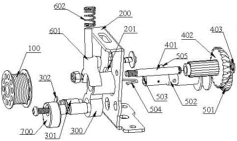
缝纫机绕线机构包括支架200、固定在支架200上的连杆300、与从动齿轮联动从而可随从动齿轮的转动而转动的锥齿轮机构、可随锥齿轮机构的转动而转动的绕线轴机构、可拨动连杆300摆动的拨叉 机构,支架200可把缝纫机绕线机构固定在机壳内,结构简单,组合安装方便。The sewing machine winding mechanism includes a
锥齿轮机构包括固设于支架200上的锥齿轴401、通过第一挡圈403转动套设于锥齿轴401上并与从动齿轮联动的锥齿轮402。The bevel gear mechanism includes a
绕线轴机构包括可与锥齿轮机构相抵并可随锥齿轮402的转动而转动的环形橡胶圈501、可随环形橡胶圈501的转动而转动的绕线轴502。绕线轴502包括与环形橡胶圈501固定连接的下端部、依次穿过支架200和连杆300的中间部、延伸至连杆300外的上端部,下端部、中间部和上端部设置为一体成型结构。绕线轴502的上端部设有开口槽503,开口槽503内嵌设有一可卡固梭芯100的卡簧504。梭芯100通过卡簧504卡固在上端部上,梭芯100可随绕线轴502的转动而转动(即梭芯100可随环形橡胶圈501的转动而转动)从而可绕线。连杆300一端通过铆钉301与支架200转动连接,另一端通过一插销505与绕线轴502转动连接,连杆300可沿着铆钉301摆动。铆钉301的端部设有可使连杆300转动固定在支架200上的第二挡圈302。外力作用于拨叉 机构,拨叉 机构拨动连杆300沿着铆钉301摆动从而使绕线轴机构随着连杆300而摆动进而使环形橡胶圈501与锥齿轮机构联动并带动绕线轴502转动最终使梭芯100绕线。在梭芯100的位置对应处设有一限位偏心轮700,限位偏心轮700可顶住梭芯100从而使绕线轴502随着梭芯100绕线量的增大而朝远离锥齿轮机构的方向移动进而使环形橡胶圈501脱离锥齿轮机构最终停止梭芯100绕线操作。The bobbin mechanism includes an
本实施例中,拨叉 机构包括换向拨叉 601、弹簧602。In this embodiment, the fork mechanism includes a reversing
本发明内置式的缝纫机绕线机构,内置于机壳内并可与电机传动机构联动从而可使固定在缝纫机绕线机构上的梭芯100自动绕线。缝纫机绕线机构包括支架200、连杆300、与从动齿轮联动的锥齿轮机构、可随锥齿轮机构的转动而转动的绕线轴机构、拨叉 机构,结构简单,设计合理,零部件少,生产成本低。支架200通过螺钉连接方式固定在机壳内从而使固定在支架200上的各部件内嵌于机壳内,而上端部穿过机壳并设于容置槽内,与支架200固定连接的限位偏心轮700穿过机壳并设于容置槽内,可固定梭芯100的上端部和限位偏心轮700均设于容置槽内,同时容置槽上可盖设一面板,当无需进行绕线操作时,面板盖设于容置槽上,缝纫机绕线机构不外露在机壳外,有效避免独立、外部设置的缝纫机绕线机构对生产过程形成干扰,确保缝纫机的工作效率和工作稳定可靠性,而且缝纫机整体外型平顺光滑,简约美观。当进行绕线操作时,打开面板,将梭芯100卡固在上端部上,然后盖上面板,拨动拨叉 机构,使连杆300沿着铆钉301摆动,由于绕线轴502穿过连杆300所以在连杆300摆动时带动绕线轴机构摆动并使绕线轴机构与锥齿轮机构相抵触,绕线轴机构的环形橡胶圈501可随锥齿轮402的转动而转动,隐藏在容置槽内的梭芯100随着绕线轴机构的转动而转动并进行绕线操作,梭芯100藏置在容置槽内,完全不占用地方,也不影响缝纫机的正常缝纫工作,提高缝纫机的工作效率,结构简单,设计合理而新颖,隐藏在机壳和容置槽内的缝纫机绕线机构,不影响缝纫机的整体架构,使得缝纫机外型简约美观。The built-in sewing machine winding mechanism of the present invention is built in the casing and can be linked with the motor transmission mechanism so that the
另外本发明的缝纫机绕线机构一改传统的结构样式,传统结构中环形橡胶圈501直接与主轴上的主齿轮的侧壁相抵连接从而使环形橡胶圈501随着主齿轮的转动而转动,环形橡胶圈501与主齿轮之间通过摩擦来相互转动,这样的结构,容易发生打滑、空转的现象,影响绕线效率,且环形橡胶圈501容易磨损,使用寿命短。本发明的缝纫机绕线机构,在支架200上转动固定一锥齿轮机构,锥齿轮机构的锥齿轮402与主轴上的从动齿轮啮合从而使锥齿轮402随着主轴的转动而转动,锥齿轮402与从动齿轮紧密啮合,不会发生接触不良、空转、打滑等现象,工作稳定性高,使用寿命长。设于绕线轴502上的环形橡胶圈501可相抵于锥齿轮402上并随锥齿轮402的转动而转动,环形橡胶圈501还可脱离锥齿轮402以实现环形橡胶圈501与锥齿轮402之间的离合效果。支架200上还设有一连杆300,连杆300一端通过铆钉301与支架200转动连接,另一端通过一插销505与绕线轴502转动连接,支架200上设有可供绕线轴502穿过并可供绕线轴502随着连杆300摆动的限位缺口201,当连杆300沿着铆钉301摆动时绕线轴502在限位缺口201内随着连杆300而摆动,通过拨叉 机构可拨动连杆300摆动从而实现环形橡胶圈501与锥齿轮402之间的离合效果,结构简单,设计合理而新颖。In addition, the sewing machine winding mechanism of the present invention is changed from the traditional structure. In the traditional structure, the
当外力作用于拨叉 机构,并通过换向拨叉 601拨动连杆300摆动,绕线轴502随着连杆300的摆动而在限位缺口201内摆动,同时固定在下端部上的环形橡胶圈501相抵于锥齿轮402外侧壁上以实现环形橡胶圈501与锥齿轮402之间的接合效果,环形橡胶圈501可随锥齿轮402的转动而转动,同时绕线轴502随着环形橡胶圈501的转动而转动,通过卡簧504卡固在上端部的梭芯100随着绕线轴502的转动而转动,最终完成梭芯100绕线操作。当梭芯100绕线量达到一定量后,梭芯100与限位偏心轮700相抵触,随着梭芯100绕线量的不断增加,梭芯100与限位偏心轮700之间的相互作用力越大,限位偏心轮700固定在支架200上,固定不动的,因此随着相互作用力的不断增大,梭芯100朝远离限位偏心轮700的方向移动,即绕线轴502随着梭芯100绕线量的增大而朝远离锥齿轮机构的方向移动从而使环形橡胶圈501脱离锥齿轮机构以实现环形橡胶圈501与锥齿轮402之间的断离效果,最终停止梭芯100绕线操作,实现自动化停止工作。操作方便,绕线速度快,梭芯100通过卡簧504卡固在上端部,绕线轴502与梭芯100之间不会发生空转、打滑等现象,工作稳定可靠,实用性强,而且在限位偏心轮700的作用下,绕线轴502会随着梭芯100绕线量的增大而朝远离锥齿轮机构的方向移动从而在满线时使环形橡胶圈501自动远离锥齿轮机构进而停止梭芯100绕线操作,可自动化停止绕线操作,自动化程度高,使用性能优越,工作效率高。When the external force acts on the fork mechanism, and the connecting
因此,本发明的一种内置式的缝纫机绕线机构解决了现有的缝纫机绕线机构结构复杂、体积大、工作效率低、自动化程度低、工作稳定性差的问题,实现了结构简单且体积小,设计合理而新颖,内置式的,零部件少,生产成本低,自动化程度高,使用性能优越等有益效果。Therefore, the built-in sewing machine winding mechanism of the present invention solves the problems of complex structure, large volume, low work efficiency, low degree of automation and poor work stability of the existing sewing machine winding mechanism, and realizes simple structure and small volume. , Reasonable and novel design, built-in type, less parts, low production cost, high degree of automation, superior performance and other beneficial effects.
以上所述仅为本发明的优选实施例,并非因此限制本发明的专利范围,凡是利用本发明说明书及附图内容所作的等效结构变换,或直接或间接运用在其他相关的技术领域,均同理包括在本发明的专利保护范围内。The above descriptions are only the preferred embodiments of the present invention, and are not intended to limit the scope of the present invention. Any equivalent structural transformation made by using the contents of the description and drawings of the present invention, or directly or indirectly applied to other related technical fields, will not limit the scope of the present invention. Similarly, it is included in the scope of patent protection of the present invention.
Claims (6)
Priority Applications (1)
| Application Number | Priority Date | Filing Date | Title |
|---|---|---|---|
| CN201611226938.0A CN106436070B (en) | 2016-12-27 | 2016-12-27 | Built-in sewing machine wire winding mechanism |
Applications Claiming Priority (1)
| Application Number | Priority Date | Filing Date | Title |
|---|---|---|---|
| CN201611226938.0A CN106436070B (en) | 2016-12-27 | 2016-12-27 | Built-in sewing machine wire winding mechanism |
Publications (2)
| Publication Number | Publication Date |
|---|---|
| CN106436070A CN106436070A (en) | 2017-02-22 |
| CN106436070B true CN106436070B (en) | 2022-05-03 |
Family
ID=58215603
Family Applications (1)
| Application Number | Title | Priority Date | Filing Date |
|---|---|---|---|
| CN201611226938.0A Active CN106436070B (en) | 2016-12-27 | 2016-12-27 | Built-in sewing machine wire winding mechanism |
Country Status (1)
| Country | Link |
|---|---|
| CN (1) | CN106436070B (en) |
Families Citing this family (3)
| Publication number | Priority date | Publication date | Assignee | Title |
|---|---|---|---|---|
| CN107190433A (en) * | 2017-07-05 | 2017-09-22 | 拓卡奔马机电科技有限公司 | A kind of winding mechanism of sewing machine |
| CN108130660B (en) * | 2018-01-27 | 2023-07-28 | 舒普智能技术股份有限公司 | Automatic winder for sewing machine and sewing machine |
| CN108265380B (en) * | 2018-03-06 | 2023-05-05 | 沈红 | Shuttle capable of quickly withdrawing weft yarn for silk tapestry |
Citations (5)
| Publication number | Priority date | Publication date | Assignee | Title |
|---|---|---|---|---|
| JP2002066184A (en) * | 2000-08-30 | 2002-03-05 | Brother Ind Ltd | Sewing machine lower thread winding device |
| CN1367286A (en) * | 2001-01-21 | 2002-09-04 | 李氏商贸株式会社 | Bobbin winding machine for sewing machine |
| JP3148341U (en) * | 2008-11-26 | 2009-02-12 | 株式会社鈴木製作所 | Sewing machine thread winding device |
| JP2012239667A (en) * | 2011-05-20 | 2012-12-10 | Juki Corp | Bobbin winder of sewing machine |
| CN104264386A (en) * | 2014-10-20 | 2015-01-07 | 杰克缝纫机股份有限公司 | Automatic bobbin changing and winding device and method |
Family Cites Families (12)
| Publication number | Priority date | Publication date | Assignee | Title |
|---|---|---|---|---|
| JPS5537092Y2 (en) * | 1975-11-13 | 1980-09-01 | ||
| CH642125A5 (en) * | 1979-12-19 | 1984-03-30 | Gegauf Fritz Ag | WINDING DEVICE ON A SEWING MACHINE. |
| JP2868735B2 (en) * | 1996-10-30 | 1999-03-10 | ジューキ株式会社 | Sewing machine lower thread supply device |
| CN2490187Y (en) * | 2000-10-23 | 2002-05-08 | 浙江中捷缝纫机有限公司 | Bobbin winding device on industrial bedjoints sewing machine |
| CN101581013A (en) * | 2008-05-13 | 2009-11-18 | 上海贵衣缝纫设备有限公司 | Motor drive internal winder |
| JP5786474B2 (en) * | 2011-06-13 | 2015-09-30 | アイシン精機株式会社 | sewing machine |
| CN202543582U (en) * | 2012-03-22 | 2012-11-21 | Juki株式会社 | Bobbin winder of sewing machine |
| CN203256460U (en) * | 2013-05-06 | 2013-10-30 | 温州欧罗华实业有限公司 | Full-automatic cop latch winding machine |
| CN203782378U (en) * | 2014-04-18 | 2014-08-20 | 桐乡市中昊机械模具有限公司 | Automatic winding machine of sewing machine |
| CN104264385B (en) * | 2014-10-20 | 2016-03-16 | 杰克缝纫机股份有限公司 | Peg or spindle overlaps bobbin case and threader and method automatically |
| CN105734850A (en) * | 2016-04-26 | 2016-07-06 | 杰克缝纫机股份有限公司 | Automatic thread winding and cutting integrated winder |
| CN206308477U (en) * | 2016-12-27 | 2017-07-07 | 中山市金冠电器科技有限公司 | A built-in sewing machine winding mechanism |
-
2016
- 2016-12-27 CN CN201611226938.0A patent/CN106436070B/en active Active
Patent Citations (5)
| Publication number | Priority date | Publication date | Assignee | Title |
|---|---|---|---|---|
| JP2002066184A (en) * | 2000-08-30 | 2002-03-05 | Brother Ind Ltd | Sewing machine lower thread winding device |
| CN1367286A (en) * | 2001-01-21 | 2002-09-04 | 李氏商贸株式会社 | Bobbin winding machine for sewing machine |
| JP3148341U (en) * | 2008-11-26 | 2009-02-12 | 株式会社鈴木製作所 | Sewing machine thread winding device |
| JP2012239667A (en) * | 2011-05-20 | 2012-12-10 | Juki Corp | Bobbin winder of sewing machine |
| CN104264386A (en) * | 2014-10-20 | 2015-01-07 | 杰克缝纫机股份有限公司 | Automatic bobbin changing and winding device and method |
Also Published As
| Publication number | Publication date |
|---|---|
| CN106436070A (en) | 2017-02-22 |
Similar Documents
| Publication | Publication Date | Title |
|---|---|---|
| CN106436070B (en) | Built-in sewing machine wire winding mechanism | |
| CN104372561A (en) | Variable-frequency simulated hand-wash motor reduction clutch and washing machine | |
| CN104264423A (en) | Drainage control device and washing machine with same | |
| CN203383596U (en) | Clutch mechanism for lock | |
| CN103790435B (en) | Handle rapid reverse mechanism | |
| CN206308477U (en) | A built-in sewing machine winding mechanism | |
| AU2013101234A4 (en) | Clutch Structure for Motor | |
| CN204391013U (en) | A kind of revolving body for miniature circuit breaker | |
| CN102606058A (en) | Automatic lifting roller blind retarder | |
| CN215214844U (en) | Ball valve with changeable flow control | |
| CN101424272B (en) | a fan | |
| CN111867697B (en) | Bouncing device and bouncing spinning toy | |
| CN203462257U (en) | Thread wiping device for sewing machine | |
| CN207527104U (en) | Valve actuator manual switching device | |
| CN209586221U (en) | Cord fabric winding and unwinding device | |
| CN104372571B (en) | A high-efficiency frequency conversion motor deceleration clutch device and washing machine | |
| CN207800539U (en) | A kind of axis connection driving structure of three axis stacked switch | |
| KR20110084476A (en) | Roll Drive of Roll Screen | |
| CN201981990U (en) | Retarder of automatic-ascending roller blind | |
| CN206887506U (en) | Washing machine and its drive system | |
| CN205752062U (en) | A circuit breaker energy storage drive mechanism | |
| CN204125763U (en) | Drain control unit and apply its washing machine | |
| CN204375591U (en) | Driving gear of auto transfer switch | |
| CN210768320U (en) | Automatic window opening and closing device easy to control clutch | |
| CN203132084U (en) | Air-conditioning panel supporting mechanism |
Legal Events
| Date | Code | Title | Description |
|---|---|---|---|
| C06 | Publication | ||
| PB01 | Publication | ||
| C10 | Entry into substantive examination | ||
| SE01 | Entry into force of request for substantive examination | ||
| GR01 | Patent grant | ||
| GR01 | Patent grant |