CN1065366C - Distribution slot with transmission bus - Google Patents
Distribution slot with transmission bus Download PDFInfo
- Publication number
- CN1065366C CN1065366C CN97126464A CN97126464A CN1065366C CN 1065366 C CN1065366 C CN 1065366C CN 97126464 A CN97126464 A CN 97126464A CN 97126464 A CN97126464 A CN 97126464A CN 1065366 C CN1065366 C CN 1065366C
- Authority
- CN
- China
- Prior art keywords
- contact
- link
- bus
- support
- distribution slot
- Prior art date
- Legal status (The legal status is an assumption and is not a legal conclusion. Google has not performed a legal analysis and makes no representation as to the accuracy of the status listed.)
- Expired - Fee Related
Links
Images

Classifications
-
- H—ELECTRICITY
- H02—GENERATION; CONVERSION OR DISTRIBUTION OF ELECTRIC POWER
- H02G—INSTALLATION OF ELECTRIC CABLES OR LINES, OR OF COMBINED OPTICAL AND ELECTRIC CABLES OR LINES
- H02G3/00—Installations of electric cables or lines or protective tubing therefor in or on buildings, equivalent structures or vehicles
- H02G3/02—Details
- H02G3/04—Protective tubing or conduits, e.g. cable ladders or cable troughs
-
- H—ELECTRICITY
- H01—ELECTRIC ELEMENTS
- H01R—ELECTRICALLY-CONDUCTIVE CONNECTIONS; STRUCTURAL ASSOCIATIONS OF A PLURALITY OF MUTUALLY-INSULATED ELECTRICAL CONNECTING ELEMENTS; COUPLING DEVICES; CURRENT COLLECTORS
- H01R25/00—Coupling parts adapted for simultaneous co-operation with two or more identical counterparts, e.g. for distributing energy to two or more circuits
- H01R25/16—Rails or bus-bars provided with a plurality of discrete connecting locations for counterparts
-
- H—ELECTRICITY
- H01—ELECTRIC ELEMENTS
- H01R—ELECTRICALLY-CONDUCTIVE CONNECTIONS; STRUCTURAL ASSOCIATIONS OF A PLURALITY OF MUTUALLY-INSULATED ELECTRICAL CONNECTING ELEMENTS; COUPLING DEVICES; CURRENT COLLECTORS
- H01R12/00—Structural associations of a plurality of mutually-insulated electrical connecting elements, specially adapted for printed circuits, e.g. printed circuit boards [PCB], flat or ribbon cables, or like generally planar structures, e.g. terminal strips, terminal blocks; Coupling devices specially adapted for printed circuits, flat or ribbon cables, or like generally planar structures; Terminals specially adapted for contact with, or insertion into, printed circuits, flat or ribbon cables, or like generally planar structures
- H01R12/50—Fixed connections
- H01R12/59—Fixed connections for flexible printed circuits, flat or ribbon cables or like structures
- H01R12/65—Fixed connections for flexible printed circuits, flat or ribbon cables or like structures characterised by the terminal
- H01R12/67—Fixed connections for flexible printed circuits, flat or ribbon cables or like structures characterised by the terminal insulation penetrating terminals
- H01R12/675—Fixed connections for flexible printed circuits, flat or ribbon cables or like structures characterised by the terminal insulation penetrating terminals with contacts having at least a slotted plate for penetration of cable insulation, e.g. insulation displacement contacts for round conductor flat cables
-
- H—ELECTRICITY
- H01—ELECTRIC ELEMENTS
- H01R—ELECTRICALLY-CONDUCTIVE CONNECTIONS; STRUCTURAL ASSOCIATIONS OF A PLURALITY OF MUTUALLY-INSULATED ELECTRICAL CONNECTING ELEMENTS; COUPLING DEVICES; CURRENT COLLECTORS
- H01R13/00—Details of coupling devices of the kinds covered by groups H01R12/70 or H01R24/00 - H01R33/00
- H01R13/02—Contact members
- H01R13/22—Contacts for co-operating by abutting
- H01R13/24—Contacts for co-operating by abutting resilient; resiliently-mounted
Landscapes
- Engineering & Computer Science (AREA)
- Architecture (AREA)
- Civil Engineering (AREA)
- Structural Engineering (AREA)
- Multi-Conductor Connections (AREA)
- Connector Housings Or Holding Contact Members (AREA)
- Details Of Connecting Devices For Male And Female Coupling (AREA)
Abstract
Description
本发明涉及一种配电线槽,它在一个盒子内包含电源配电连接件和具有一个双线通信信号传输和/或控制总线,下文也将通信信号称为低电位信号。The present invention relates to a distribution duct, which contains power distribution connections in a box and has a two-wire communication signal transmission and/or control bus, the communication signal is also referred to as a low-potential signal hereinafter.
配电线槽一般包括在盒体中每隔一定距离分布的分支架,该分支架设有合适的开口以便电源和控制总线能相互连接,该连接件本身还与用电设备,如由电源导线供电的负载相连接,以此它被用于交换低电位信号。The distribution wire duct generally includes sub-supports distributed at certain distances in the box body. The sub-supports are provided with suitable openings so that the power supply and the control bus can be connected to each other. connected to the load, so that it is used to exchange low-level signals.
这种类型的配电线槽公开在文献EP-673089中,它在每个分支架中包括两个总线连接部件,分别与支架和连接件相连接,这两个连接部件用机械和电学方法耦接在一起,以便在总线和与导线相连接的负载之间形成通信和/或控制连线。This type of distribution duct is disclosed in the document EP-673089, which includes two bus connection parts in each sub-support, respectively connected to the bracket and the connector, and these two connection parts are coupled mechanically and electrically. connected together to form a communication and/or control connection between the bus and the load connected to the wires.
毫无疑问,在恶劣的环境中的配电线槽,其坚固性和连接性能是总线连接的基本质量要求,特别是双扭线或其它双线总线。Undoubtedly, the sturdiness and connection performance of distribution ducts in harsh environments are the basic quality requirements for bus connections, especially twisted pair or other two-wire buses.
本发明的目的是改善在上述类型的配电线槽中的分支架的位置上低位信号传输总线的连接质量和其可靠性。The object of the present invention is to improve the connection quality and the reliability of the low-level signal transmission bus at the position of the sub-rack in a distribution duct of the above-mentioned type.
根据本发明,与支架(或连接件)相连接的连接部件设有两个插入绝缘体的两弹性接触支件,用于与总线中的每个导线相连接,同时,与连接件(或支架)相连接的连接部件设有刚性接触面,该接触面能与凸出绝缘体的两弹性支件的接触面形成接触。According to the present invention, the connection part connected with the bracket (or the connector) is provided with two elastic contact supports inserted into the insulator, used to be connected with each wire in the bus, and at the same time, connected with the connector (or bracket) The connected connecting parts are provided with rigid contact surfaces capable of coming into contact with the contact surfaces of the two elastic supports protruding from the insulator.
最好情况是,与支架相连接的连接部件包括折弯的导电件,每个导电件在其一端至少设有一个接触叉头,该叉头用于移去绝缘体并装入总线中的一根,在其另一端自身向后折弯的支脚形成具有接触面的弹性支件,这些接触面相互平行偏移并垂直于线槽的长度方向。Preferably, the connecting part to the bracket comprises bent conductors each provided at one end with at least one contact prong for removing the insulator and fitting into one of the bus lines. , the legs bent back on themselves at the other end form an elastic support with contact surfaces offset parallel to each other and perpendicular to the length direction of the slot.
与连接件相连接的连接部件可以插入支架上的专设的槽,这样每个连接件能被连接,它包括一个沿连接件插入的方向而延伸的金属连接支件,同时一绝缘条能模制地插入连接臂中,该绝缘条在垂直于线槽的长度方向和插入方向的方向上较薄。The connecting parts connected with the connecting parts can be inserted into the dedicated grooves on the bracket, so that each connecting part can be connected, and it includes a metal connecting support extending along the direction in which the connecting parts are inserted, while an insulating strip can The insulating strip is relatively thin in the direction perpendicular to the length direction of the slot and the insertion direction.
下面的说明是非限制性实施例,参考下面的附图,描述本发明的优点和效果。The following description is a non-limiting example, with reference to the following drawings, describing the advantages and effects of the invention.
图1是本发明的配电线槽的立体示意图;Fig. 1 is the three-dimensional schematic view of distribution wire groove of the present invention;
图2是图1的配电线槽中与支架相连接的连接部件及与分支连接件相连接的连接部件的部分分解透视图;Fig. 2 is a partial exploded perspective view of the connection parts connected to the bracket and the connection parts connected to the branch connectors in the distribution wire duct of Fig. 1;
图3是与分支架相连接的连接部件的分解透视图;Fig. 3 is the exploded perspective view of the connecting part connected with the sub-support;
图4是与连接件相连接的连接装置的透视图;Fig. 4 is the perspective view of the connecting device connected with the connecting piece;
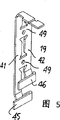
图5是用于制成图4中连接装置的导电件的扁片。FIG. 5 is a flat sheet used to form the conductive member of the connecting device in FIG. 4. FIG.
如图1所示,配电线槽包括一个成型金属盒10,例如是挤压成型的,它含有并行的导线,即电源导线11,它可以是单层导线,或者是带状电缆,或者是导电杆,还包含低电位、控制或仪表信号传输导线12;在此情况下,导线12是一个扭绞的或未扭绞的双电线总线。As shown in Figure 1, the distribution duct comprises a profiled metal box 10, such as extruded, which contains parallel conductors, namely power conductors 11, which may be single-layer conductors, or ribbon cables, or The conductive rod, also contains the low potential, control or instrumentation signal transmission conductor 12; in this case the conductor 12 is a twisted or untwisted two-wire bus.
配电线槽沿长度x-x′方向延伸,它包括由绝缘材料制成的、每隔一定间隔设置的固定的分支架13,这些支架制成盒体状,每个支架包括一个在盒体的纵面10a设置的开口14,该开口设有分支连接件15专有的连接插头沿垂直于x-x′方向的y-y′插入的槽16,18。槽16是用于电源连接插头17插入的,槽18是用于形成信号连接部件22的插销19插入的,插头和插销是沿y-y′方向设置的。The distribution duct extends along the length x-x' direction, and it includes fixed sub-supports 13 made of insulating material at regular intervals. These supports are made into a box shape, and each support includes a The opening 14 provided on the surface 10a is provided with slots 16, 18 into which the dedicated connecting plug of the branch connector 15 is inserted along the y-y' direction perpendicular to the x-x' direction. The slot 16 is used for inserting the power connection plug 17, and the slot 18 is used for inserting the
连接部件21是通过熔焊和/或定位销固定在支架20的侧壁上,该连接部件连接在导线12上以便它能通过移去或穿过绝缘体与该导线相连接。形成连接部件22的插销19沿y-y′方向向下凸出连接件15的本体。The connecting
如图2和3所示,将会看得更清楚,与支架相连接的连接部件2l由通过切削和折弯的金属扁片形成的两个导电件23,24组成,每个导电件23,24在其一端具有两个叉头25a,25b,它们用于移开绝缘体以便导线12能够插入叉头的底端,在叉头的另一端设有分别位于弹性臂27a,27b端部的两接触面26a,26b,弹性臂27a,27b是通过从导电件的扁片面29开始向后折弯支脚28而形成的,它们的主表面相互接触,接触面26是由设置在臂27端部的凸部30而形成的,它们的接触点位于这些凸部的边缘。As shown in Figures 2 and 3, it will be seen more clearly that the
导电件相对一个垂直x-x′的平面而对称。它们被容置在两个绝缘件31,32之间,两个绝缘件相互组装以形成一体和连接部件。绝缘件31包含夹持件33和定位件35,夹持件33与附加于支架侧壁上的夹持件34接合,定位件35固定在支架上。绝缘件32包括臂27的端部和它们的凸部30能通过的开口36,37,它们还能通过侧壁20上的一个开口插入槽18中。注意开口36,37首先沿纵向x-x′,然后沿连接件插入的方向y-y′相互偏移。The conductive member is symmetrical about a plane perpendicular to x-x'. They are housed between two
与连接件相连接的连接部件22设有通过折弯和切削金属条40(图5)而形成的两连接臂41,42。The connecting part 22 to which the connecting piece is connected is provided with two connecting
侧片41,42在一端和与负载相连接的连接件的导线43,44相连接,在另一端分别设有通过使片条沿x-x′方向折弯而形成的扁条45,46,每个扁条设计成能与导电件23,24的两接触面26a,26b相配合,扁条45,46的长度要适合于锁定连接件所必需的沿x-x′方向移动的距离。扁条40能模制地插入在与x-x′和y-y′相垂直的z-z′方向上较薄的绝缘扁条47中,这样,它在连接件中占有较小的空间;该扁条然后在48被穿孔以切削最初位于侧片41,42之间的连片49。
当连接件15沿y-y′方向插入线槽盒的开口14中时,它是通过沿y-y′方向设置的翼片15a插入支架13的槽(未示)中;沿相同方向设置的电源插头17插入槽16中,插销19插入槽18中。导电条45,46在臂27的凸部30插入槽18中时,两接触面26a,26b凸向槽的内侧,导电条通过使臂27弯曲,并沿z-z′方向推压导电条而能接合这些接触面。应该明白在此情况下,连接质量非常良好,连接性能也非常可靠。When the connector 15 is inserted into the opening 14 of the trunk box along the y-y' direction, it is inserted into the groove (not shown) of the bracket 13 through the fin 15a arranged along the y-y' direction; the power plug 17 arranged along the same direction is inserted into In the slot 16 , the
Claims (6)
Applications Claiming Priority (2)
| Application Number | Priority Date | Filing Date | Title |
|---|---|---|---|
| FR9615623 | 1996-12-17 | ||
| FR9615623A FR2757323B1 (en) | 1996-12-17 | 1996-12-17 | ELECTRICAL DISTRIBUTION PIPING TO TRANSMISSION BUS |
Publications (2)
| Publication Number | Publication Date |
|---|---|
| CN1185674A CN1185674A (en) | 1998-06-24 |
| CN1065366C true CN1065366C (en) | 2001-05-02 |
Family
ID=9498847
Family Applications (1)
| Application Number | Title | Priority Date | Filing Date |
|---|---|---|---|
| CN97126464A Expired - Fee Related CN1065366C (en) | 1996-12-17 | 1997-12-17 | Distribution slot with transmission bus |
Country Status (7)
| Country | Link |
|---|---|
| US (1) | US5967818A (en) |
| EP (1) | EP0849829B1 (en) |
| KR (1) | KR100450335B1 (en) |
| CN (1) | CN1065366C (en) |
| DE (1) | DE69713046T2 (en) |
| ES (1) | ES2176647T3 (en) |
| FR (1) | FR2757323B1 (en) |
Families Citing this family (12)
| Publication number | Priority date | Publication date | Assignee | Title |
|---|---|---|---|---|
| CA2356524C (en) * | 1998-12-30 | 2008-04-22 | Zumtobel Staff Gmbh | Lighting strip system and a method of mounting a lighting strip system |
| US6328596B1 (en) * | 2000-04-06 | 2001-12-11 | International Business Machines Corporation | Plug and cable for information appliances |
| US6445571B1 (en) * | 2000-06-01 | 2002-09-03 | Astec International Limited | Combined DC/data bus for electrical equipment |
| US6676281B2 (en) * | 2001-05-23 | 2004-01-13 | Sea Gull Lighting Products, Inc. | Rail lighting system |
| US6848933B1 (en) | 2001-11-13 | 2005-02-01 | Rockwell Automation Technologies, Inc. | System and methodology providing coordinated and modular conveyor zone control |
| AU2003251967A1 (en) | 2002-07-15 | 2004-07-14 | Haworth, Inc. | Solid wire modular electrical system for office areas |
| FR2844641B1 (en) * | 2002-09-16 | 2004-10-22 | Valeo Electronique Sys Liaison | WIRING ASSEMBLY AND CORRESPONDING CONNECTOR |
| JP2005176539A (en) * | 2003-12-12 | 2005-06-30 | Yazaki Corp | Box fixing structure |
| KR100689872B1 (en) | 2005-01-21 | 2007-03-09 | 김상용 | Distribution Bus Duct |
| DE102012013034A1 (en) * | 2012-06-29 | 2014-01-02 | Wolfgang Rixen | channel system |
| US9685730B2 (en) | 2014-09-12 | 2017-06-20 | Steelcase Inc. | Floor power distribution system |
| JP7265458B2 (en) * | 2019-09-26 | 2023-04-26 | 日本航空電子工業株式会社 | Connector and connection method |
Citations (4)
| Publication number | Priority date | Publication date | Assignee | Title |
|---|---|---|---|---|
| EP0419031A1 (en) * | 1989-08-28 | 1991-03-27 | The Whitaker Corporation | Electrical tap connector |
| EP0610786A2 (en) * | 1993-02-09 | 1994-08-17 | Molex Incorporated | Insulation displacement termination system for input-output electrical connector |
| EP0670197A2 (en) * | 1994-02-02 | 1995-09-06 | Deutsche Gardner-Denver GmbH & Co | Conveyor track with successive conveyor sections and common busbar. |
| EP0673089A1 (en) * | 1994-03-17 | 1995-09-20 | Schneider Electric Sa | Cable duct and its manufacturing process |
Family Cites Families (9)
| Publication number | Priority date | Publication date | Assignee | Title |
|---|---|---|---|---|
| US4085988A (en) * | 1977-01-27 | 1978-04-25 | Westinghouse Electric Corporation | Bus duct plug-in ground stab |
| FR2514576A1 (en) * | 1981-10-13 | 1983-04-15 | Telemecanique Electrique | PHASE SELECTOR CLAMP CONNECTOR FOR ELECTRICAL DISTRIBUTION PIPES |
| US5064380A (en) * | 1989-08-28 | 1991-11-12 | Amp Incorporated | Electrical tap and splice connector |
| US4954098A (en) * | 1989-11-01 | 1990-09-04 | Minnesota Mining And Manufacturing Company | Sealed insulation displacement connector |
| US5203711A (en) * | 1991-10-01 | 1993-04-20 | Molex Incorporated | Modular interchangeable power distribution system |
| FR2717011B1 (en) * | 1994-03-02 | 1996-03-29 | Telemecanique | Connector for electrical pipe. |
| JP2935165B2 (en) * | 1994-12-06 | 1999-08-16 | 矢崎総業株式会社 | Assembly method and structure of press-fit joint connector |
| JP3117379B2 (en) * | 1995-01-23 | 2000-12-11 | 矢崎総業株式会社 | Crimp joint connector |
| US5662491A (en) * | 1995-12-07 | 1997-09-02 | Chrysler Corporation | Electrical connector for vehicle power component switches |
-
1996
- 1996-12-17 FR FR9615623A patent/FR2757323B1/en not_active Expired - Fee Related
-
1997
- 1997-12-17 ES ES97403071T patent/ES2176647T3/en not_active Expired - Lifetime
- 1997-12-17 EP EP97403071A patent/EP0849829B1/en not_active Expired - Lifetime
- 1997-12-17 DE DE69713046T patent/DE69713046T2/en not_active Expired - Lifetime
- 1997-12-17 CN CN97126464A patent/CN1065366C/en not_active Expired - Fee Related
- 1997-12-17 KR KR1019970070205A patent/KR100450335B1/en not_active Expired - Fee Related
- 1997-12-17 US US08/992,469 patent/US5967818A/en not_active Expired - Lifetime
Patent Citations (4)
| Publication number | Priority date | Publication date | Assignee | Title |
|---|---|---|---|---|
| EP0419031A1 (en) * | 1989-08-28 | 1991-03-27 | The Whitaker Corporation | Electrical tap connector |
| EP0610786A2 (en) * | 1993-02-09 | 1994-08-17 | Molex Incorporated | Insulation displacement termination system for input-output electrical connector |
| EP0670197A2 (en) * | 1994-02-02 | 1995-09-06 | Deutsche Gardner-Denver GmbH & Co | Conveyor track with successive conveyor sections and common busbar. |
| EP0673089A1 (en) * | 1994-03-17 | 1995-09-20 | Schneider Electric Sa | Cable duct and its manufacturing process |
Also Published As
| Publication number | Publication date |
|---|---|
| EP0849829A1 (en) | 1998-06-24 |
| FR2757323B1 (en) | 1999-01-22 |
| KR19980064298A (en) | 1998-10-07 |
| CN1185674A (en) | 1998-06-24 |
| US5967818A (en) | 1999-10-19 |
| ES2176647T3 (en) | 2002-12-01 |
| KR100450335B1 (en) | 2005-01-17 |
| FR2757323A1 (en) | 1998-06-19 |
| DE69713046T2 (en) | 2002-10-31 |
| EP0849829B1 (en) | 2002-06-05 |
| DE69713046D1 (en) | 2002-07-11 |
Similar Documents
| Publication | Publication Date | Title |
|---|---|---|
| CN217881991U (en) | Electricity taking insertion sheet, plug box and bus system | |
| CN1074592C (en) | Electrical connector for power and signal contacts | |
| US4635359A (en) | Method of manufacturing multi-terminal electrical connector | |
| US6004163A (en) | Electrical multi-pole plug-and-socket-type connector with associated socket part | |
| KR950034297A (en) | Wire harness and manufacturing method thereof | |
| JP2016143665A (en) | Electrical contact means and electrical cable assemblies for the automotive industry | |
| IE53733B1 (en) | A connecting device | |
| US4223971A (en) | Electrical wiring assembly and method | |
| KR960006145A (en) | Flat cable with conductor end connectable to the connector | |
| JP2655073B2 (en) | Electrical connector | |
| CN1069450C (en) | Connector for electric cable | |
| US6059601A (en) | Single-sided press-pinching connector and a method of making same | |
| KR100450335B1 (en) | Electrical distribution duct with transmission bus | |
| CN1205120A (en) | 110-type wire connection device | |
| KR940010427B1 (en) | Electrical cable assembly with selected side cable entry | |
| JPH10507571A (en) | Flexible electrical conductor | |
| KR0122784Y1 (en) | Small electric motor with electrical connector | |
| WO1993003517A1 (en) | Flexible conductive track | |
| JPS6330121Y2 (en) | ||
| JP2568405B2 (en) | Multi-pair connector for cable | |
| JP2735488B2 (en) | Electrical connector | |
| US7201602B2 (en) | Terminal fitting for surface mounting | |
| CN2378847Y (en) | Plug type connector | |
| US5676557A (en) | Electrical trunking and method of manufacturing the same | |
| JPH0110863Y2 (en) |
Legal Events
| Date | Code | Title | Description |
|---|---|---|---|
| C06 | Publication | ||
| PB01 | Publication | ||
| C10 | Entry into substantive examination | ||
| SE01 | Entry into force of request for substantive examination | ||
| C14 | Grant of patent or utility model | ||
| GR01 | Patent grant | ||
| CF01 | Termination of patent right due to non-payment of annual fee |
Granted publication date: 20010502 Termination date: 20151217 |
|
| EXPY | Termination of patent right or utility model |