CN106802482B - Connector and Head Mounted Display - Google Patents
Connector and Head Mounted Display Download PDFInfo
- Publication number
- CN106802482B CN106802482B CN201610847808.2A CN201610847808A CN106802482B CN 106802482 B CN106802482 B CN 106802482B CN 201610847808 A CN201610847808 A CN 201610847808A CN 106802482 B CN106802482 B CN 106802482B
- Authority
- CN
- China
- Prior art keywords
- display device
- bracket
- electronic display
- front case
- electronic device
- Prior art date
- Legal status (The legal status is an assumption and is not a legal conclusion. Google has not performed a legal analysis and makes no representation as to the accuracy of the status listed.)
- Active
Links
Images


Classifications
-
- G—PHYSICS
- G02—OPTICS
- G02B—OPTICAL ELEMENTS, SYSTEMS OR APPARATUS
- G02B27/00—Optical systems or apparatus not provided for by any of the groups G02B1/00 - G02B26/00, G02B30/00
- G02B27/01—Head-up displays
- G02B27/017—Head mounted
- G02B27/0176—Head mounted characterised by mechanical features
-
- G—PHYSICS
- G06—COMPUTING OR CALCULATING; COUNTING
- G06F—ELECTRIC DIGITAL DATA PROCESSING
- G06F1/00—Details not covered by groups G06F3/00 - G06F13/00 and G06F21/00
- G06F1/16—Constructional details or arrangements
- G06F1/1613—Constructional details or arrangements for portable computers
- G06F1/1632—External expansion units, e.g. docking stations
-
- G—PHYSICS
- G02—OPTICS
- G02B—OPTICAL ELEMENTS, SYSTEMS OR APPARATUS
- G02B27/00—Optical systems or apparatus not provided for by any of the groups G02B1/00 - G02B26/00, G02B30/00
- G02B27/02—Viewing or reading apparatus
- G02B27/022—Viewing apparatus
-
- G—PHYSICS
- G02—OPTICS
- G02B—OPTICAL ELEMENTS, SYSTEMS OR APPARATUS
- G02B27/00—Optical systems or apparatus not provided for by any of the groups G02B1/00 - G02B26/00, G02B30/00
- G02B27/02—Viewing or reading apparatus
- G02B27/028—Viewing or reading apparatus characterised by the supporting structure
-
- G—PHYSICS
- G06—COMPUTING OR CALCULATING; COUNTING
- G06F—ELECTRIC DIGITAL DATA PROCESSING
- G06F1/00—Details not covered by groups G06F3/00 - G06F13/00 and G06F21/00
- G06F1/16—Constructional details or arrangements
- G06F1/1613—Constructional details or arrangements for portable computers
- G06F1/163—Wearable computers, e.g. on a belt
-
- G—PHYSICS
- G06—COMPUTING OR CALCULATING; COUNTING
- G06F—ELECTRIC DIGITAL DATA PROCESSING
- G06F3/00—Input arrangements for transferring data to be processed into a form capable of being handled by the computer; Output arrangements for transferring data from processing unit to output unit, e.g. interface arrangements
- G06F3/01—Input arrangements or combined input and output arrangements for interaction between user and computer
- G06F3/011—Arrangements for interaction with the human body, e.g. for user immersion in virtual reality
-
- G—PHYSICS
- G09—EDUCATION; CRYPTOGRAPHY; DISPLAY; ADVERTISING; SEALS
- G09G—ARRANGEMENTS OR CIRCUITS FOR CONTROL OF INDICATING DEVICES USING STATIC MEANS TO PRESENT VARIABLE INFORMATION
- G09G5/00—Control arrangements or circuits for visual indicators common to cathode-ray tube indicators and other visual indicators
-
- H—ELECTRICITY
- H05—ELECTRIC TECHNIQUES NOT OTHERWISE PROVIDED FOR
- H05K—PRINTED CIRCUITS; CASINGS OR CONSTRUCTIONAL DETAILS OF ELECTRIC APPARATUS; MANUFACTURE OF ASSEMBLAGES OF ELECTRICAL COMPONENTS
- H05K5/00—Casings, cabinets or drawers for electric apparatus
- H05K5/02—Details
- H05K5/0204—Mounting supporting structures on the outside of casings
-
- H—ELECTRICITY
- H05—ELECTRIC TECHNIQUES NOT OTHERWISE PROVIDED FOR
- H05K—PRINTED CIRCUITS; CASINGS OR CONSTRUCTIONAL DETAILS OF ELECTRIC APPARATUS; MANUFACTURE OF ASSEMBLAGES OF ELECTRICAL COMPONENTS
- H05K5/00—Casings, cabinets or drawers for electric apparatus
- H05K5/02—Details
- H05K5/0217—Mechanical details of casings
-
- H—ELECTRICITY
- H05—ELECTRIC TECHNIQUES NOT OTHERWISE PROVIDED FOR
- H05K—PRINTED CIRCUITS; CASINGS OR CONSTRUCTIONAL DETAILS OF ELECTRIC APPARATUS; MANUFACTURE OF ASSEMBLAGES OF ELECTRICAL COMPONENTS
- H05K5/00—Casings, cabinets or drawers for electric apparatus
- H05K5/02—Details
- H05K5/03—Covers
-
- H—ELECTRICITY
- H05—ELECTRIC TECHNIQUES NOT OTHERWISE PROVIDED FOR
- H05K—PRINTED CIRCUITS; CASINGS OR CONSTRUCTIONAL DETAILS OF ELECTRIC APPARATUS; MANUFACTURE OF ASSEMBLAGES OF ELECTRICAL COMPONENTS
- H05K5/00—Casings, cabinets or drawers for electric apparatus
- H05K5/10—Casings, cabinets or drawers for electric apparatus comprising several parts forming a closed casing
- H05K5/15—Casings, cabinets or drawers for electric apparatus comprising several parts forming a closed casing assembled by resilient members
-
- G—PHYSICS
- G02—OPTICS
- G02B—OPTICAL ELEMENTS, SYSTEMS OR APPARATUS
- G02B27/00—Optical systems or apparatus not provided for by any of the groups G02B1/00 - G02B26/00, G02B30/00
- G02B27/01—Head-up displays
- G02B27/0101—Head-up displays characterised by optical features
- G02B2027/0132—Head-up displays characterised by optical features comprising binocular systems
-
- G—PHYSICS
- G02—OPTICS
- G02B—OPTICAL ELEMENTS, SYSTEMS OR APPARATUS
- G02B27/00—Optical systems or apparatus not provided for by any of the groups G02B1/00 - G02B26/00, G02B30/00
- G02B27/01—Head-up displays
- G02B27/0101—Head-up displays characterised by optical features
- G02B2027/014—Head-up displays characterised by optical features comprising information/image processing systems
-
- H—ELECTRICITY
- H04—ELECTRIC COMMUNICATION TECHNIQUE
- H04M—TELEPHONIC COMMUNICATION
- H04M1/00—Substation equipment, e.g. for use by subscribers
- H04M1/02—Constructional features of telephone sets
- H04M1/04—Supports for telephone transmitters or receivers
Landscapes
- Engineering & Computer Science (AREA)
- Physics & Mathematics (AREA)
- General Physics & Mathematics (AREA)
- Theoretical Computer Science (AREA)
- General Engineering & Computer Science (AREA)
- Optics & Photonics (AREA)
- Computer Hardware Design (AREA)
- Human Computer Interaction (AREA)
- Microelectronics & Electronic Packaging (AREA)
- Casings For Electric Apparatus (AREA)
Abstract
本发明提供一种头戴式显示装置和联接器。该头戴式显示装置包括:主框架,包括透镜;前壳,包括安置区域和外围区域,电子装置安置于安置区域中,外围区域围绕电子装置的周边的至少一部分;连接器支架,从外围区域的一侧可水平地移动并在电子装置被安装时在围绕电子装置的一侧的至少一部分的同时电连接到电子装置的连接端口;以及固定支架,从外围区域的一侧可水平地移动并在电子装置被安装时围绕电子装置的相反侧表面的一部分。
The present invention provides a head mounted display device and a connector. The head-mounted display device includes: a main frame including a lens; a front case including a placement area and a peripheral area in which the electronic device is placed, the peripheral area surrounding at least a portion of the periphery of the electronic device; a connector bracket from the peripheral area one side of the electronic device is horizontally movable and electrically connected to a connection port of the electronic device while surrounding at least a part of one side of the electronic device when the electronic device is installed; and a fixing bracket horizontally movable from one side of the peripheral area and A portion of the opposite side surface surrounding the electronic device when the electronic device is mounted.
Description
技术领域technical field
本公开涉及头戴式显示装置。The present disclosure relates to head mounted display devices.
背景技术Background technique
近年来,已经开发了可以安装在用户的身体上的各种电子装置。该装置通常被称为可穿戴电子装置。In recent years, various electronic devices that can be mounted on a user's body have been developed. This device is often referred to as a wearable electronic device.
可安装在身体的任何部分上的可穿戴电子装置例如可以包括安装在用户的头上以显示图像的头戴式显示(HMD)装置、智能眼镜、智能手表或腕带、隐形眼镜型装置、戒指型装置、鞋型装置、衣服型装置以及手套型装置,并可以被各种各样地附着到人身体或衣服的一部分或者从身体或衣服的一部分分离,具体地,HMD装置可以具有护目镜形状或眼镜片形状。Wearable electronic devices that can be mounted on any part of the body can include, for example, head-mounted display (HMD) devices that are mounted on a user's head to display images, smart glasses, smart watches or wristbands, contact lens-type devices, rings type devices, shoe-type devices, clothing-type devices, and glove-type devices, and can be variously attached to or detached from a part of a person's body or clothing, in particular, HMD devices can have the shape of goggles or spectacle lens shape.
可穿戴电子装置可以改善用户的可携带性和可访问性,因为它直接安装到身体上。Wearable electronics can improve portability and accessibility for users as it mounts directly to the body.
HMD装置可以配置为使得电子装置安装在其框架上。然而,电子装置已经发展为具有各种尺寸和形状。因此,因为HMD装置需要根据电子装置的形式而被各种各样地制造,所以它们在生产线和销售的方面具有许多问题。The HMD device may be configured such that the electronic device is mounted on its frame. However, electronic devices have been developed to have various sizes and shapes. Therefore, since HMD devices need to be variously manufactured according to the form of electronic devices, they have many problems in terms of production lines and sales.
以上信息被给出作为背景信息,仅用于帮助本公开的理解。关于以上中的任何信息是否可应用作为关于本公开的现有技术,没有做出决定,也没有做出断言。The above information is presented as background information only to assist with an understanding of the present disclosure. No determination has been made, and no assertion is made, as to whether any of the above information is applicable as prior art with regard to the present disclosure.
发明内容SUMMARY OF THE INVENTION
本公开的方面将解决处理至少上述问题和/或缺点并提供至少如下所述的优点。因此,本公开的一方面是提供联接器以及包括该联接器的头戴式显示装置,该连接器可以安装和固定电子装置而电子装置的形式没有被限制。Aspects of the present disclosure are to address at least the above-mentioned problems and/or disadvantages and to provide at least the advantages described below. Therefore, an aspect of the present disclosure is to provide a connector and a head mounted display device including the same, which can mount and fix an electronic device without limitation in the form of the electronic device.
根据本公开的一方面,提供一种头戴式显示装置。该头戴式显示装置包括:主框架,包括透镜;前壳,包括电子装置安置于其中的安置区域和围绕电子装置的周边的至少一部分的外围区域;连接器支架,相对于前壳的安置区域的底部从外围区域的一侧可水平地移动,并在电子装置被安装时,在围绕电子装置的一侧的至少一部分的同时电连接到电子装置的连接端口;以及固定支架,相对于前壳的安置区域的底部从外围区域的一侧可水平地移动,并在电子装置被安装时,围绕电子装置的相反侧表面的一部分。According to an aspect of the present disclosure, a head-mounted display device is provided. The head-mounted display device includes: a main frame including a lens; a front case including a seating area in which an electronic device is seated and a peripheral area surrounding at least a portion of a periphery of the electronic device; a connector bracket, a seating area relative to the front case a bottom portion of which is horizontally movable from one side of the peripheral area, and is electrically connected to a connection port of the electronic device while surrounding at least a part of one side of the electronic device when the electronic device is installed; and a fixing bracket, relative to the front case The bottom of the mounting area is horizontally movable from one side of the peripheral area and surrounds a portion of the opposite side surface of the electronic device when the electronic device is mounted.
根据本公开的另一个方面,提供一种联接器。联接器包括:前壳,包括电子装置被安置于其中的安置区域和围绕电子装置的周边的外围区域,该前壳包括:连接器支架,配置为从相对于前壳的安置区域的底部从外围区域的一侧水平地移动,并在电子装置被安装时,在围绕电子装置的一侧的侧表面的至少一部分的同时电连接到电子装置的连接端口;以及固定支架,相对于前壳的安置区域的底部从外围区域的一侧水平地移动,并在电子装置被安装时围绕电子装置的相反侧表面的一部分。According to another aspect of the present disclosure, a coupling is provided. The connector includes a front case including a seating area in which the electronic device is seated and a peripheral area surrounding a periphery of the electronic device, the front case including a connector bracket configured to extend from the periphery from a bottom relative to the seating area of the front case one side of the area moves horizontally and is electrically connected to a connection port of the electronic device while surrounding at least a part of a side surface of one side of the electronic device when the electronic device is mounted; and a fixing bracket, relative to the placement of the front case The bottom of the area moves horizontally from one side of the peripheral area and surrounds a portion of the opposite side surface of the electronic device when the electronic device is mounted.
对于本领域的技术人员而言,本公开的其它方面、优点和显著的特征将从以下详细描述变得明显,该详细描述结合附图公开了本公开的各种实施方式。Other aspects, advantages, and salient features of the present disclosure will become apparent to those skilled in the art from the following detailed description, which, taken in conjunction with the accompanying drawings, discloses various embodiments of the present disclosure.
附图说明Description of drawings
本公开的某些实施方式的以上和其它的方面、特征和优点将从以下结合附图的描述而变得更明显,附图中:The above and other aspects, features and advantages of certain embodiments of the present disclosure will become more apparent from the following description taken in conjunction with the accompanying drawings, in which:
图1是根据本公开的一实施方式的头戴式显示(HMD)装置的构造的透视图;1 is a perspective view of a configuration of a head mounted display (HMD) device according to an embodiment of the present disclosure;
图2是在图1的HMD装置没有联接到根据本公开的一实施方式的电子装置的状态下主框架的透视图;2 is a perspective view of a main frame in a state in which the HMD device of FIG. 1 is not coupled to an electronic device according to an embodiment of the present disclosure;
图3是在电子装置和盖安装在根据本公开的一实施方式的HMD装置上的状态下图2的后部透视图;3 is a rear perspective view of FIG. 2 in a state in which the electronic device and the cover are mounted on the HMD device according to an embodiment of the present disclosure;
图4是根据本公开的一实施方式的使用者穿戴图2的HMD装置的状态视图;4 is a state view of a user wearing the HMD device of FIG. 2 according to an embodiment of the present disclosure;
图5A是示出根据本公开的一实施方式的处于第一状态的HMD装置的前壳的连接器支架的视图;5A is a view showing a connector bracket of a front case of an HMD device in a first state according to an embodiment of the present disclosure;
图5B是示出根据本公开的一实施方式的处于第二状态的HMD装置的前壳的连接器支架的视图;5B is a view showing a connector bracket of a front case of an HMD device in a second state according to an embodiment of the present disclosure;
图5C是示出根据本公开的一实施方式的处于第三状态的HMD装置的前壳的连接器支架的视图;5C is a view showing a connector bracket of a front case of an HMD device in a third state according to an embodiment of the present disclosure;
图5D是示出根据本公开的一实施方式的处于第四状态的HMD装置的前壳的连接器支架的视图;5D is a view showing a connector bracket of a front case of an HMD device in a fourth state according to an embodiment of the present disclosure;
图6A是根据本公开的一实施方式的连接器支架的分解透视图;6A is an exploded perspective view of a connector bracket according to an embodiment of the present disclosure;
图6B是示出根据本公开的一实施方式的处于第一状态的连接器支架的视图;6B is a view showing the connector bracket in a first state according to an embodiment of the present disclosure;
图6C是示出根据本公开的一实施方式的连接器支架的第一剖切面A-A'的视图;6C is a view showing a first cutaway plane AA' of a connector bracket according to an embodiment of the present disclosure;
图6D是示出根据本公开的一实施方式的连接器支架的第二剖切面B-B'的视图;6D is a view showing a second cutaway plane BB' of the connector bracket according to an embodiment of the present disclosure;
图6E是示出根据本公开的一实施方式的连接器支架的运动状态的视图;6E is a view showing a moving state of the connector holder according to an embodiment of the present disclosure;
图6F是示出根据本公开的一实施方式的处于第三状态的连接器支架的剖切面的视图;6F is a view showing a cutaway view of the connector bracket in a third state according to an embodiment of the present disclosure;
图6G是示出根据本公开的一实施方式的处于第四状态的连接器支架的剖切面的视图;6G is a view showing a cutaway view of the connector bracket in a fourth state according to an embodiment of the present disclosure;
图6H是根据本公开的一实施方式的连接器支架和前壳的分解透视图;6H is an exploded perspective view of a connector bracket and front housing according to an embodiment of the present disclosure;
图7A是示出根据本公开的一实施方式的处于第一状态的HMD装置的前壳的固定支架的视图;7A is a view showing a fixing bracket of a front case of an HMD device in a first state according to an embodiment of the present disclosure;
图7B是示出根据本公开的一实施方式的处于第二状态的HMD装置的前壳的固定支架的视图;7B is a view showing a fixing bracket of the front case of the HMD device in a second state according to an embodiment of the present disclosure;
图7C是示出根据本公开的一实施方式的处于第三状态的HMD装置的前壳的固定支架的视图;7C is a view showing a fixing bracket of the front case of the HMD device in a third state according to an embodiment of the present disclosure;
图8A是根据本公开的一实施方式的固定支架的分解透视图;8A is an exploded perspective view of a fixed bracket according to an embodiment of the present disclosure;
图8B是示出根据本公开的一实施方式的固定支架的第一状态的视图;8B is a view showing a first state of the fixing bracket according to an embodiment of the present disclosure;
图8C是示出根据本公开的一实施方式的处于第一状态的固定支架的透视图;8C is a perspective view showing the fixing bracket in a first state according to an embodiment of the present disclosure;
图8D是示出根据本公开的一实施方式的处于第二状态的固定支架的视图;8D is a view showing the fixing bracket in a second state according to an embodiment of the present disclosure;
图8E是示出根据本公开的一实施方式的固定支架的运动状态的视图;8E is a view illustrating a motion state of the fixing bracket according to an embodiment of the present disclosure;
图8F是示出根据本公开的一实施方式的处于第二状态的连接器支架的第一剖切面C-C'的视图;8F is a view showing a first cutaway plane CC' of the connector holder in a second state according to an embodiment of the present disclosure;
图8G是示出根据本公开的一实施方式的处于第三状态的连接器支架的第一剖切面A-A'的视图;8G is a view showing a first cutaway plane AA' of the connector bracket in a third state according to an embodiment of the present disclosure;
图8H是示出根据本公开的一实施方式的处于第三状态的连接器支架的第二剖切面D-D'的视图;8H is a view showing a second cutaway plane DD' of the connector bracket in a third state according to an embodiment of the present disclosure;
图8I是根据本公开的一实施方式的固定支架和前壳的分解透视图;8I is an exploded perspective view of a fixed bracket and front case according to an embodiment of the present disclosure;
图9A是根据本公开的一实施方式的侧壁保护器的分解透视图;9A is an exploded perspective view of a sidewall protector according to an embodiment of the present disclosure;
图9B是示出根据本公开的一实施方式的侧壁保护器和前壳的联接状态的视图;9B is a view showing a coupled state of the side wall protector and the front case according to an embodiment of the present disclosure;
图10是示意地示出根据本公开的一实施方式的HMD装置的构造的框图;10 is a block diagram schematically showing the configuration of an HMD device according to an embodiment of the present disclosure;
图11是根据本公开的一实施方式的HMD装置的正常模式、头戴模式(HMM)或虚拟现实(VR)模式的视图;以及11 is a view of a normal mode, a head mounted mode (HMM), or a virtual reality (VR) mode of an HMD device according to an embodiment of the present disclosure; and
图12是示出根据本公开的一实施方式的HMD装置通过使用智能手机的后部摄像头而提供透视模式的视图。FIG. 12 is a view illustrating that the HMD device provides a see-through mode by using a rear camera of a smartphone according to an embodiment of the present disclosure.
在整个图中,应当注意到,同样的附图标记用来示出相同或类似的元件、特征和结构。Throughout the drawings, it should be noted that the same reference numerals are used to designate the same or similar elements, features and structures.
具体实施方式Detailed ways
参照附图的以下描述被提供来帮助对如权利要求书及其等同物限定的本公开的各种实施方式的全面理解。它包括各种细节以帮助所述理解,但是这些将被认为仅是示范性的。因此,本领域普通技术人员将认识到,可以进行这里描述的各种实施方式的各种变化和变型,而没有脱离本公开的范围和精神。此外,为了清晰和简洁,对众所周知的功能和结构的描述可以被省略。The following description with reference to the accompanying drawings is provided to assist in a comprehensive understanding of various embodiments of the present disclosure as defined by the claims and their equivalents. It includes various details to aid that understanding, but these are to be considered exemplary only. Accordingly, those of ordinary skill in the art will recognize that various changes and modifications of the various embodiments described herein can be made without departing from the scope and spirit of the present disclosure. Also, descriptions of well-known functions and constructions may be omitted for clarity and conciseness.
在以下的描述和权利要求中使用的术语和词语不限于著书目录的意义,而是仅被发明人使用以使得能够清楚且一致地理解本公开。因此,对于本领域技术人员应当显然的是,本公开的各种实施方式的以下描述仅被提供用于说明的目的,而不是为了限制如权利要求及其等同物限定的本公开。The terms and words used in the following description and claims are not limited to the bibliographical meanings, but, are merely used by the inventor to enable a clear and consistent understanding of the present disclosure. Accordingly, it should be apparent to those skilled in the art that the following description of various embodiments of the present disclosure is provided for illustration purposes only and not for the purpose of limiting the present disclosure as defined by the claims and their equivalents.
将理解,单数形式“一”、“一个”和“该”也包括复数指示物,除非上下文另外清楚地指示。因此,例如,参照“一部件表面”包括参照一个或更多个这样的表面。It will be understood that the singular forms "a," "an," and "the" include plural referents as well, unless the context clearly dictates otherwise. Thus, for example, reference to "a component surface" includes reference to one or more of such surfaces.
这里使用的术语“具有”、“可以具有”、“包括”、“可以包括”、“包含”等指示对应特征(例如,数字、功能、操作或元件)的存在,而不排除另外特征的存在。The terms "having," "may have," "including," "may include," "comprising," etc. as used herein indicate the presence of corresponding features (eg, numbers, functions, operations, or elements), but do not preclude the presence of additional features .
术语“A或B”、“A和/或B中的至少一个”、或“A和/或B中的一个或更多个”可以包括一起列出的项目的所有可能组合。例如,术语“A或B”、“A和B中的至少一个”或“A或B中的至少一个”可以表示(1)包括至少一个A、(2)包括至少一个B以及(3)包括至少一个A和至少一个B的所有情形。The terms "A or B," "at least one of A and/or B," or "one or more of A and/or B" can include all possible combinations of items listed together. For example, the terms "A or B," "at least one of A and B," or "at least one of A or B" can mean (1) include at least one A, (2) include at least one B, and (3) include All cases of at least one A and at least one B.
这里使用的术语“第一”、“第二”等可以修饰各种元件,而与其次序和/或优先级无关,并仅用于将一个元件与另一个元件区别开,而不限制所述元件。例如,“第一用户装置”和“第二用户装置”可以指示不同的用户装置而与次序或优先级无关。例如,第一元件可以被称为第二元件,反之亦然,而没有背离本公开的范围。The terms "first", "second", etc., as used herein, may modify various elements regardless of their order and/or priority, and are used only to distinguish one element from another and not to limit the element . For example, "first user device" and "second user device" may refer to different user devices regardless of order or priority. For example, a first element could be termed a second element, and vice versa, without departing from the scope of the present disclosure.
将理解,当某一元件(例如第一元件)被称为“与……可操作地或通信地联接或者可操作地或通信地联接到”或“连接到”另一个元件(例如第二元件)时,该某一元件可以直接联接到所述另一个元件或者经由另一个元件(例如第三元件)联接到所述另一个元件。然而,当某一元件(例如第一元件)被称为“直接联接”或“直接连接”到另一个元件(例如第二元件)时,在该元件和所述另一个元件之间可以没有插入元件(例如第三元件)。It will be understood that when an element (eg, a first element) is referred to as being "operably or communicatively coupled or operatively or communicatively coupled to" or "connected to" another element (eg, a second element) ), the certain element may be directly coupled to the other element or coupled to the other element via another element (eg, a third element). However, when an element (eg, a first element) is referred to as being "directly coupled" or "directly connected" to another element (eg, a second element), there may be no intervening element between the element and the other element element (eg, a third element).
如这里使用的术语“配置(或设定)为”可以与术语例如“适于”、“具有……的能力”、“被设计为”、“适合于”、“被制成为”或“能够”可交换地使用。术语“配置(或设定)为”可以不必具有“专门设计为”的含义。在某些情形下,术语“配置为……的器件”可以指示该器件与其它器件或元件仪器一起“可以执行”。例如,术语“配置(或设定)为执行A、B、C……的处理器”可以表示用于执行对应操作的专用处理器(例如嵌入式处理器)、或用于执行存储在存储器件中的至少一个软件程序以执行对应操作的通用处理器(例如中央处理器(CPU)或应用处理器)。The term "configured (or configured) to be" as used herein may be combined with terms such as "adapted to", "capable of", "designed to", "adapted to", "made to be" or "capable of" " are used interchangeably. The term "configured (or set) to" may not necessarily have the meaning of "specifically designed to". In some cases, the term "a device configured to" may indicate that the device "may execute" in conjunction with other devices or component instruments. For example, the term "processor configured (or set up) to perform A, B, C..." may refer to a special purpose processor (eg, an embedded processor) for performing the corresponding operation, or a processor for performing storage stored in a memory device At least one software program in a general-purpose processor (eg, a central processing unit (CPU) or an application processor) to perform corresponding operations.
这里使用的术语仅用于描述具体的实施方式,而不旨在限制其他实施方式的范围。单数形式的术语可以包括复数形式,除非另作说明。这里使用的术语,包括技术或科学术语,具有与本领域的普通技术人员所理解的相同含义。在这里使用的术语当中,在通用词典中限定的术语可以被解释为具有与在现有技术中限定的上下文意义相同或类似的含义,而不应被解释为理想化或过度地形式化的含义,除非另外地明确地限定。取决于该情形,即使在这里限定的术语也不应被这样地解释而排除本公开的各种实施方式。The terminology used herein is used to describe particular embodiments only and is not intended to limit the scope of other embodiments. Terms in the singular may include the plural unless stated otherwise. Terms used herein, including technical or scientific terms, have the same meaning as understood by one of ordinary skill in the art. Among the terms used herein, terms defined in general dictionaries may be interpreted as having the same or similar meanings as the contextual meanings defined in the prior art, and should not be interpreted as idealized or overly formalized meanings , unless explicitly defined otherwise. Depending on the circumstances, even the terms defined herein should not be so construed as to exclude various embodiments of the present disclosure.
根据本公开的各种实施方式的电子装置可以包括智能手机、平板个人计算机(PC)、移动电话、可视电话、电子书阅读器、桌面PC、膝上型PC、笔记本计算机、工作站、服务器、个人数字助理(PDA)、便携式多媒体播放器(PMP)、运动图像专家组(MPEG-1或MPEG-2)音频层3(MP3)播放器、移动医疗装置、照相机或可穿戴装置中的至少一个。可穿戴装置可以包括附件型器件(例如手表、戒指、手镯、脚镯、项链、眼镜、隐形眼镜、头戴式显示(HMD)装置)、织物或衣服集成型器件(例如电子服装)、身体附着型器件(例如皮肤垫或纹身)、或可生物植入型器件(例如可植入电路)中的至少一个。Electronic devices according to various embodiments of the present disclosure may include smartphones, tablet personal computers (PCs), mobile phones, video phones, e-book readers, desktop PCs, laptop PCs, notebook computers, workstations, servers, At least one of a personal digital assistant (PDA), a portable multimedia player (PMP), a Moving Picture Experts Group (MPEG-1 or MPEG-2) audio layer 3 (MP3) player, a mobile medical device, a camera, or a wearable device . Wearable devices may include accessory-type devices (eg, watches, rings, bracelets, anklets, necklaces, glasses, contact lenses, head-mounted display (HMD) devices), fabric or clothing-integrated devices (eg, electronic clothing), body attachments at least one of a bioimplantable device (eg, a skin pad or tattoo), or a bioimplantable device (eg, an implantable circuit).
根据本公开的实施方式,电子装置可以是家用电器。该家用电器可以包括例如电视机(TV)、数字多用途盘(DVD)播放器、音频播放器、电冰箱、空气调节器、清洁器、烘箱、微波炉、洗衣机、空气净化器、机顶盒、家庭自动化控制面板、安全控制面板、电视盒(例如三星HomeSyncTM、苹果TVTM或谷歌TVTM)、游戏控制台(例如XboxTM或PlayStationTM)、电子词典、电子开关、录像摄像机或电子像框中的至少一个。According to an embodiment of the present disclosure, the electronic device may be a home appliance. The household appliances may include, for example, television sets (TVs), digital versatile disc (DVD) players, audio players, refrigerators, air conditioners, cleaners, ovens, microwave ovens, washing machines, air purifiers, set-top boxes, home automation Control panels, security control panels, TV boxes (such as Samsung HomeSync TM , Apple TV TM or Google TV TM ), game consoles (such as Xbox TM or PlayStation TM ), electronic dictionaries, electronic switches, video cameras or electronic picture frames at least One.
根据本公开的实施方式,一种电子装置可以包括各种医疗装置(例如各种便携式医学测量装置(例如血糖测量装置、心率测量装置、血压测量装置、体温测量装置等)、磁共振血管学(MRA)装置、磁共振成像(MRI)装置、计算机断层摄影(CT)装置、扫描仪、超声波设备等)、导航装置、全球导航卫星系统(GNSS)、事件数据记录器(EDR)、飞行数据记录器(FDR)、车辆信息娱乐装置、用于船的电子设备(例如导航系统、回转罗盘等)、航空电子学、安全装置、用于车辆的音响本体(head unit)、工业或家用机器人、自动取款机(ATM)、销售点(POS)终端或物联网(IoT)装置(例如灯泡、各种传感器、电或燃气表、喷洒器、火警、恒温器、街灯、烘炉、健身器材、热水槽、加热器、煮器等)中的中的至少一个。According to an embodiment of the present disclosure, an electronic device may include various medical devices (eg, various portable medical measurement devices (eg, blood glucose measurement device, heart rate measurement device, blood pressure measurement device, body temperature measurement device, etc.), magnetic resonance angiography ( MRA) devices, magnetic resonance imaging (MRI) devices, computed tomography (CT) devices, scanners, ultrasound equipment, etc.), navigation devices, global navigation satellite systems (GNSS), event data recorders (EDR), flight data recording devices (FDR), vehicle infotainment, electronics for boats (e.g. navigation systems, gyrocompass, etc.), avionics, safety devices, head units for vehicles, industrial or domestic robots, automatic Cash Machine (ATM), Point of Sale (POS) terminal or Internet of Things (IoT) devices (e.g. light bulbs, various sensors, electricity or gas meters, sprinklers, fire alarms, thermostats, street lights, ovens, fitness equipment, hot water tanks , heater, boiler, etc.) at least one.
根据本公开的实施方式,电子装置可以包括家具或建筑/结构的部分、电子板、电子签名接收装置、投影仪或测量仪器(例如水表、电量计、燃气表、波长计等)中的至少一个。电子装置可以是以上装置的一个或多个组合。电子装置可以是柔性装置。电子装置不限于上述装置,而是可以随着新技术的发展而包括新的电子装置。According to embodiments of the present disclosure, electronic devices may include at least one of furniture or parts of buildings/structures, electronic boards, electronic signature receivers, projectors, or measuring instruments (eg, water meters, electricity meters, gas meters, wavelength meters, etc.) . The electronic device may be one or more combinations of the above. The electronic device may be a flexible device. The electronic devices are not limited to the above-mentioned devices, but may include new electronic devices as new technologies are developed.
在下文,将参照附图描述根据本公开的实施方式的电子装置。如这里使用的术语“用户”可以指使用电子装置的人或可以指的是使用电子装置的装置(例如人工智能装置)。Hereinafter, an electronic device according to an embodiment of the present disclosure will be described with reference to the accompanying drawings. The term "user" as used herein may refer to a person using an electronic device or may refer to a device (eg, an artificial intelligence device) using the electronic device.
根据本公开的各种实施方式的HMD装置可以提供透视模式或不透视模式中的至少一个,透视模式提供增强现实(AR)模式,不透视模式通过显示器提供虚拟现实(AR)图像。The HMD device according to various embodiments of the present disclosure may provide at least one of a see-through mode that provides an augmented reality (AR) mode or a non-see-through mode that provides a virtual reality (AR) image through a display.
透视模式(see-through mode)可以通常指的是例如在谷歌GlassTM中向用户显示内容(例如图像或虚拟物体)使得用户在用户的视场内感知到该内容以及在外部环境中的物体的模式。当HMD装置处于透视模式时所显示的内容可以被显示在显示器或透明/半透明的眼镜上。在透视模式中,与用户的外部环境中的物体有关的附加信息和/或图像可以被提供给用户。See-through mode may generally refer to displaying content (eg, images or virtual objects) to a user such as in Google Glass ™ such that the user perceives the content and objects in the external environment within the user's field of view. model. The content displayed when the HMD device is in see-through mode can be displayed on a display or transparent/translucent glasses. In the see-through mode, additional information and/or images related to objects in the user's external environment may be provided to the user.
不透视模式(see-closed mode)可以通常指的是例如在索尼HMZTM中通过使用全息图向用户显示附加信息的模式。在不透视模式中,图像通过投射两个或更多光束产生从而使用光干涉产生立体图像,使得用户可以在HMD内观看作为三维图像的内容(例如游戏、电影、流媒体广播等)。当不透视模式被实现时,用户可以感觉沉浸在该内容中。因此,本公开的HMD装置可以与现有的HMD装置区别开。A see-closed mode may generally refer to a mode in which additional information is displayed to the user by using a hologram, eg in a Sony HMZ ™ . In no see-through mode, the image is created by projecting two or more light beams to create a stereoscopic image using optical interference, so that the user can view content (eg, games, movies, streaming broadcasts, etc.) as a three-dimensional image within the HMD. When no see-through mode is implemented, the user can feel immersed in the content. Therefore, the HMD device of the present disclosure can be distinguished from the existing HMD device.
根据本公开的各种实施方式的可拆卸地安装到HMD装置的主框架的电子装置还可以包括通信功能。The electronic device detachably mounted to the main frame of the HMD device according to various embodiments of the present disclosure may further include a communication function.
图1示出根据本公开的一实施方式的HMD装置的构造。FIG. 1 shows the configuration of an HMD device according to an embodiment of the present disclosure.
图2是示出其中既没有电子装置也没有盖安装在根据本公开的一实施方式的HMD装置上的状态的视图。2 is a view showing a state in which neither an electronic device nor a cover is mounted on the HMD device according to an embodiment of the present disclosure.
图3是示出其中电子装置和盖安装在根据本公开的一实施方式的HMD装置上的状态的透视图。3 is a perspective view showing a state in which an electronic device and a cover are mounted on an HMD device according to an embodiment of the present disclosure.
图4是示出用户穿戴根据本公开的一实施方式的HMD装置的视图。FIG. 4 is a view showing a user wearing an HMD device according to an embodiment of the present disclosure.
参照图1至图4,根据本公开的各种实施方式的HMD装置100可以包括主框架110和支撑件115(例如,带子(band))。根据各种实施方式,HMD装置100可以仅包括支撑件115的绕用户的头定位的部分,而不包括定位在用户的头上方的部分。1 to 4 , the
主框架110可以佩戴在用户的脸的至少一部分(例如脸面)上,并可以通过利用各种元件而被支撑在用户的脸面上。The
在一实施方式中,主框架110可以通过调整由回弹性(resilient)材料形成的支撑件115的带子的长度而固定为围绕用户的眼睛的周边。缓冲垫(cushion)可以附接到带子上以在HMD装置100操作达延长的一段时间时提供舒适或支撑。另外地或备选地,支撑件115可以包括眼镜腿、头盔和/或带(strap)。In one embodiment, the
主框架110的后表面可以包括与用户的脸面(facial side)接触的部分。例如,脸面接触部分130可以具有对应于用户的脸部的弯曲的结构并可以至少部分地包括回弹主体134。回弹主体134的至少一部分可以由诸如海绵或垫料(padding)的至少一个缓冲垫形成以在脸面接触部分130与用户接触时向用户提供舒适或支撑。回弹主体134可以包括一个海绵,或者可以是其中具有不同的压缩值或密度的一个或更多个海绵被结合的一个。例如,回弹主体134可以是其中三个层(例如上层、中间层和下层)被结合的海绵,其中上层和下层可以由具有低压缩值的海绵形成,中间层可以由具有高压缩值的海绵形成。The rear surface of the
根据另一个实施方式,回弹主体134可以可移除地附接到主框架110使得回弹主体134可以是从主框架110可分离的。回弹主体134的一个表面可以包括接合构件。包括在回弹主体134中的接合构件可以用于将回弹主体134附接到主框架110以及使回弹主体134从主框架110分离。接合构件可以是VelcroTM、胶带或者粘合剂,但是本公开不限于此,可以使用用于附接和分离的任何接合构件。通过使用可移除的回弹主体134,当一个HMD装置100被几个用户使用时,回弹主体134可以在不同的用户之间改变以最好地适合单独的用户。例如,回弹主体134可以配置用于成年人或孩子,或者回弹主体134可以包括不同的轮廓以对应于不同的面部特征和/或结构等。此外,当回弹主体134的表面被弄脏(例如,被化妆品、汗水等)或者回弹主体134的至少一部分由于其频繁使用而损坏时,在使用HMD装置100时,可以用另一个回弹主体134代替该回弹主体134。According to another embodiment, the
在本公开的HMD 100中,例如主框架110的形状或结构可以具有覆盖用户的眼睛的外部形状,并可以包括在内表面上的鼻凹陷120使得用户的鼻子可以位于鼻凹陷120中,从而HMD装置100可以容易地戴在用户的脸上。包括至少一个透镜的透镜组件可以在对应于用户的眼睛的位置处被插入脸面接触部分130中。当用户佩戴HMD装置100时,透镜的至少一个表面可以暴露到脸面接触部分130,使得用户可以看到电子装置200的屏幕。In the
此外,主框架110可以由重量轻并可以支撑电子装置200的材料例如塑料材料形成。Also, the
主框架110还可以包括用于保护本公开的HMD装置100的保护材料。作为另一个实施方式,保护材料可以包括各种材料例如玻璃、塑料(例如ABS或聚碳酸酯)、陶瓷、金属(例如铝)和金属合金(例如钢、不锈钢、钛或镁合金)中的至少一种,用于提高强度或刚性。The
主框架110可以包括触摸板112、显示位置调整部件114和透镜固定部件116。此外,具有用于联接的空间或结构的前壳122可以形成在主框架110的前表面上。主框架110还可以包括与已经可移除地联接到主框架110的电子装置200通信的连接器。The
在一实施方式中,连接器可以包括通用串行总线(USB)连接器,该USB连接器可以连接到电子装置200的电连接部分,例如USB端口,图形用户接口(GUI)的信号可以通过USB连接器的电连接部分被提供到电子装置200。In one embodiment, the connector may include a Universal Serial Bus (USB) connector, which may be connected to an electrical connection portion of the
主框架110的前壳122可以对应于电子装置200的外部形状。在一实施方式中,前壳122可以包括回弹性材料或柔性材料以接收各种尺寸的电子装置200。The
根据本公开的各种实施方式的HMD装置100还可以包括盖220。盖220可以将电子装置200的至少一部分固定到主框架110。The
盖220可以以钩的形式或以使用例如磁体或电磁体的方式物理地联接到主框架110。这样,盖220可以额外地防止电子装置200无意地从主框架110分离,并可以在构成主框架110的外观的同时改善美学方面。The
盖220还可以包括在其前表面上的窗口240。窗口240用于通过各种材料和各种颜色来改善美学方面。窗口240可以由一般的塑性材料诸如聚碳酸酯(PC)或压克力(acryl)形成,可以由陶瓷材料诸如玻璃、蓝宝石或透明陶瓷制造,还可以由金属材料诸如铝或不锈钢制造。当窗口240由透明材料形成时,它可以包括颜色或可以包括允许窗口240的透明性被调整的材料。The
此外,盖220还可以包括一个或多个开口222。开口222可以将由电子装置200产生的热容易地发射到盖220的外面,因此可以通过降低电子装置200的温度而防止电子装置200的性能由于热引起的退化。此外,盖220的重量可以由于一个或多个开口222而变轻,从而可以降低HMD装置100的总重量,这有益于重量减轻。Additionally, the
显示器或透明/半透明透镜260可以一体地或可拆卸地固定到主框架110的透镜固定部116。在一实施方式中,透镜组件可以被插入在电子装置200和用户之间。主框架110的后表面可以由柔软的材料(例如海绵或橡胶)形成,以防止主框架110不期望地附着于用户的眼睛的周边。The display or transparent/
在一实施方式中,主框架110可以包括可控制电子装置200或用户输入模块的控制器件。In one embodiment, the
控制器件可以包括在主框架110的侧表面上的触摸板112、物理按键、物理按钮、触摸式按键、操纵杆或转轮中的至少一个。The control device may include at least one of the
在本实施方式中,触摸板112可以显示GUI,电子装置200的功能可以通过该GUI控制。例如,从电子装置200输出的音频的音量可以通过用于声音的设定的GUI调整,或者由电子装置200显示的图像可以通过用于图像的再现的GUI控制。此外,触摸板112可以接收触摸输入(例如,通过直接触摸该触摸板112进行的输入)或用户的悬停(hovering)输入。由于本公开的HMD装置100通过使用USB等的接口连接到电子装置200,所以接收的触摸输入可以被传输到电子装置200。In this embodiment, the
电子装置200可以响应于已经从HMD装置100接收到的触摸输入而控制对应于该触摸输入的功能。例如,电子装置200可以响应于在触摸板112处收到的所接收的触摸输入而调整在电子装置200处的音量或控制图像的再现。The
根据一实施方式,显示位置调整部件114可以具有转轮或刻度盘的形式。如果用户转动被实现为显示位置调整部件114的转轮或刻度盘,则电子装置200可以移动以使得电子装置200的显示器和用户之间的距离可以被调整,结果,用户可以调整电子装置200的位置以观看适合于他或她的视线的图像或被最优地显示的图像。另外,主框架110的前壳122可以包括连接器支架500和固定支架600,该连接器支架500和固定支架600可以用于将电子装置200固定到主框架110。According to one embodiment, the display
图5A是示出根据本公开的一实施方式的处于第一状态的HMD装置的前壳的连接器支架的视图。5A is a view showing a connector bracket of a front case of an HMD device in a first state according to an embodiment of the present disclosure.
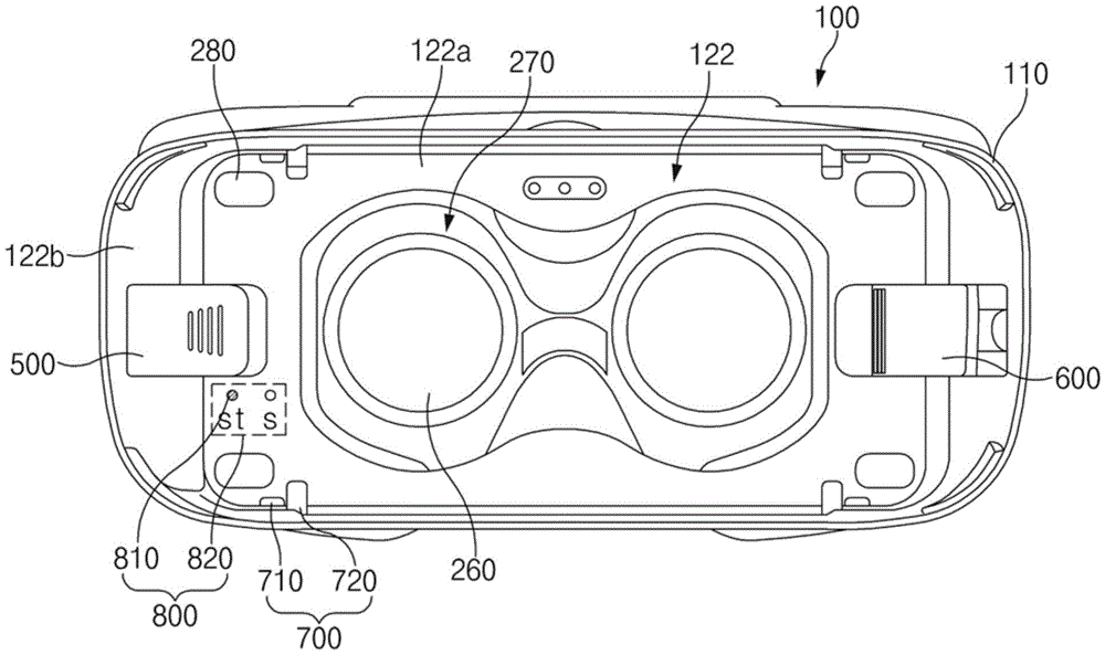
参照图5A,HMD装置100可以包括主框架110的前壳122。前壳122可以包括透镜260位于其中的透镜孔270、远离透镜孔270布置的装置保护部件280、装置侧壁保护部件700、连接器支架500、和固定支架600。此外,前壳122可以包括指示置的类型的指示部件800。前壳122还可以包括安置区域122a和围绕安置区域122a的外围区域122b,电子装置200在安置区域122a中安置在其中央部分处。透镜孔270、装置保护部件280和装置侧壁保护部件700可以布置在安置区域122a中。连接器支架500和固定支架600布置在外围区域122b中,连接器支架500和固定支架600中的至少一部分可以突出到安置区域122a。Referring to FIG. 5A , the
透镜孔270例如可以布置在前壳122的中央部处,并且透镜孔270可以具有特定的尺寸。例如,透镜孔270可以包括对应于用户的双眼的两个孔。备选地,透镜孔270可以包括一个孔。The
装置保护部件280可以在前壳122的在透镜孔270之外的特定位置处从前壳122的安置区域122a的底表面突出。当电子装置200安装在前壳122的安置区域122a上时,装置保护部件280可以物理地接触电子装置200。装置保护部件280可以由具有张力、缓冲或密度的材料形成。例如,装置保护部件280可以由各种材料诸如橡胶材料、绒布材料和丝材料形成。参照附图,尽管装置保护部件280可以位于安置区域122a的四个位置,但是本公开的实施方式不限于此。例如,可以布置一个或多个装置保护部件280。此外,装置保护部件280可以布置在安置区域122a的周边的对称位置处,使得电子装置200可以均匀地安置在安置区域122a中。The
装置侧壁保护部件700例如可以保护安置在前壳122的安置区域122a中的电子装置200的侧壁。装置侧壁保护部件700例如可以布置在与在其中布置装置保护部件280的区域相邻的区域中。可选地,装置侧壁保护部件700可以布置在安置区域122a的外围区域的至少一侧。装置侧壁保护部件700可以以对应于电子装置200的各种形式的形式布置。装置侧壁保护部件700例如可以包括保护一种类型的电子装置的侧壁的第一侧壁保护器710以及保护不同类型的电子装置的侧壁的第二侧壁保护器720。将参照图9A和图9B描述装置侧壁保护部件700的另一个示例。The device
连接器支架500例如可以布置在前壳122的左侧和右侧中的至少一个上。例如,可电连接到电子装置200的连接器可以布置在连接器支架500中。此外,连接器支架500可以具有在连接到连接器的同时围绕电子装置200的侧壁的形式(例如,C形状)。因此,当连接器和围绕电子装置200的侧壁的形状两者被布置时,连接器支架500可以具有E形状。连接器支架500可以通过外部压力调整为各种状态。例如,连接器支架500可以例如处于其朝向前壳122的安置区域122a进一步突出的状态、其朝向前壳122的外围区域122b倾斜的状态、其从朝向安置区域122a进一步突出的状态绕前壳122的安置区域122a的底部在第一方向上(例如向上)旋转的状态、以及其在从朝向外围区域122b倾斜的状态绕前壳122的安置区域122a的底部向上旋转的状态。The
如所示的,图5A的连接器支架500可以具有其朝向前壳122的外围区域122b倾斜的第一状态。如上所述,连接器支架500可以提供为关于平行于前壳122的方向朝向前壳122的中央部或前壳122的周边横向地移动。此外,连接器支架500可以绕前壳122的安置区域122a的底部向上旋转,然后可以再次朝向安置区域122a的底部旋转。As shown, the
固定支架600可以关于前壳122的纵向中心线与连接器支架500对称地布置在前壳122的外围区域122b中。如上所述,固定支架600的至少一部分可以朝向前壳122的安置区域122a突出。固定支架600可以在所示的附图中在前壳122的横向方向上移动特定的长度。根据各种实施方式,固定支架600可以包括回弹构件,该回弹构件可以提供朝向前壳122的安置区域122a的中央部的回弹力。The fixing
指示部件800可以包括指示安置在前壳122中的电子装置200的类型的多个印刷区域820以及暴露孔810,该暴露孔810根据连接器支架500的移动状态而暴露指示任一个电子装置200的类型的指示部件800的至少一部分。印刷区域820例如可以印刷在前壳122的安置区域122a的底部上。此外,印刷区域可以被浮雕或凹雕在安置区域122a的底部上。暴露孔810可以布置在安置区域122a的底部的一部分处,使得布置在暴露孔810下面的指示器的至少一部分可以暴露到外面。指示部件800可以布置在连接器支架500的一侧并且指示部件800的位置可以随着连接器支架500移动而变化。根据一实施方式,当连接器支架500朝向前壳122的外围区域122b倾斜时,指示部件800可以通过指示该指示部件800的印刷区域820中的与第一类型的电子装置相关的一个印刷区域的暴露孔810暴露。此外,当连接器支架500朝向前壳122的安置区域122a倾斜时,指示部件800可以通过指示该指示部件800的印刷区域820中的与第二类型的电子装置相关的一个印刷区域的暴露孔810暴露。The indicating
如上所述,在根据一实施方式的HMD装置100中,连接器支架500和固定支架600可以从前壳122的中央部朝向外面或者从外面朝向前壳122的中央部移动。因此,HMD装置100可以将具有各种尺寸和长度的电子装置的显示器固定在透镜孔270的区域的特定位置。此外,由于HMD装置100配置为使得连接器支架500和固定支架600关于前壳122的前表面是向上和向下可旋转的,所以电子装置200可以被容易地插入和分离。As described above, in the
图5B是示出根据本公开的一实施方式的处于第二状态的HMD装置的前壳的连接器支架的视图。5B is a view illustrating a connector bracket of a front case of an HMD device in a second state according to an embodiment of the present disclosure.
参照图5B,根据一实施方式,如所示的,HMD装置100的连接器支架500可以处于其可水平地移动以朝向前壳122的安置区域122a进一步突出的第二状态。根据各种实施方式,连接器支架500可以在通过被朝向主框架110的内部(例如朝向脸面)挤压特定高度并在面对前壳122的安置区域122a的底部的方向(垂直于前壳122的安置区域122a的方向)上从前壳122的上侧施加压力时在前壳122的水平方向上移动。根据一实施方式,用户可以在连接器支架500的上部分被朝向主框架110的安装侧挤压时通过朝向前壳122的左侧或右侧施加力而改变连接器支架500的位置。5B , according to an embodiment, as shown, the
图5B示出在垂直地向下施加力到图5A的连接器支架500时当朝向前壳122的安置区域122a的中央部(例如向右)施加力时连接器支架500的移动状态。随着连接器支架500移动,布置在连接器支架500的一侧并且其至少一部分通过形成在安置区域122a中的孔暴露的指示部件800可以指示表示另一个类型电子装置的指定印刷区域820。5B shows a moving state of the
图5C是示出根据本公开的实施方式的处于第三状态的HMD装置的前壳的连接器支架的视图。5C is a view illustrating a connector bracket of a front case of an HMD device in a third state according to an embodiment of the present disclosure.
参照图5C,如所示的,HMD装置100的连接器支架500可以配置为关于前壳122的安置区域122a的底部是向上可旋转的。因此,连接器支架500可以处于其从第一状态在一个方向上旋转的第三状态。例如,用户可以在紧握连接器支架500的一端(例如右端)时利用连接器支架500的弯曲运动施加力。因此,如所示的,平行于前壳122的安置区域122a布置的结合件510可以布置为面对前壳122的前侧。当结合件510面对前壳122的前侧(例如天空)时,可以暴露布置在结合件510内部的连接器514。用户可以将电子装置200的一侧插入到连接器514中。例如,电子装置200的USB端口可以与连接器514联接。根据各种实施方式,当电子装置200的长度是第一尺寸或第一长度时,如所示的,连接器支架500的结合件510朝向外围区域122b倾斜,用户可以在将电子装置200插入到连接器支架500中以固定电子装置200之后通过将电子装置200插入到固定支架600中而将具有第一尺寸或第一长度的电子装置200布置在透镜孔270的中央部。Referring to FIG. 5C , as shown, the
图5D是示出根据本公开的一实施方式的处于第四状态的HMD装置的前壳的连接器支架的视图。5D is a view showing a connector bracket of a front case of an HMD device in a fourth state according to an embodiment of the present disclosure.
参照图5D,HMD装置100的连接器支架500可以处于其从第二状态在特定的方向上旋转的第四状态。例如,连接器支架500可以从其移动以比在外围区域122b中朝向前壳122的安置区域122a进一步突出的状态旋转,使得结合件510面对上侧(例如,朝向天空)。Referring to FIG. 5D , the
图6A是根据本公开的一实施方式的连接器支架的分解透视图。6A is an exploded perspective view of a connector bracket according to an embodiment of the present disclosure.
参照图6A,连接器支架500可以包括结合件510和支撑构件520。结合件510可以包括连接装置支架511、连接帽512、第一回弹构件513、连接器514、指示器516和支架橡胶515。支撑构件520可以包括滑动按钮521、第二回弹构件523、连接滑块524、滑块帽525和滑动支撑件526。Referring to FIG. 6A , the
电子装置200的一侧(例如电子装置200的其中布置电连接支撑件的下端)可以插入结合件510中。同时,布置在结合件510内部的连接器514可以被插入布置在电子装置200的下端处的连接端口中。支撑构件520可以在支撑结合件510的同时允许结合件510水平地移动。支撑构件520可以允许结合件510被固定在特定位置处。One side of the electronic device 200 (eg, the lower end of the
例如,如所示的,连接装置支架511可以具有弯曲的外轮廓,并可以具有C形状使得其一侧围绕电子装置200的侧壁。此外,连接装置支架511可以包括至少一个销511a,该至少一个销511a在其一侧连接到提供在连接滑块524的一侧上的环524a,使得连接装置支架511在旋转特定角度以联接到连接滑块524时不与连接滑块524分离。连接装置支架511的外轮廓的至少一部分可以被纹理化,使得在用户施加力之后,当连接装置支架511被挤压时手指不滑动。For example, as shown, the connecting
连接帽512定位在连接装置支架511内部,并可以包括基本上面对电子装置200的侧壁的区域。连接帽512具有比连接装置支架511的尺寸小的尺寸,并可以定位在连接装置支架511内部。连接帽512可以具有C形状以围绕电子装置200的侧壁的一部分。此外,连接帽512可以包括至少一个孔,支架橡胶515通过该至少一个孔突出穿过其一侧。The
第一回弹构件513可以在连接器支架500旋转时提供回弹力以允许连接器支架500返回到初始状态(例如第一状态或第二状态)。例如,第一回弹构件513可以在联接到连接装置支架511的所述至少一个销511a中的任一个时定位在连接滑块524的一侧并固定到连接滑块524的一侧。因此,第一回弹构件513在连接器支架500在特定方向上旋转时被卷绕力推动,并且如果外部压力被释放,第一回弹构件513可以施加回弹力以使得连接器支架500返回到初始状态。例如,第一回弹构件513在连接器支架500从前壳122的安置区域122a的底部向上旋转时被推动以施加回弹力,使得连接器支架500返回到安置区域122a的底部。The first
连接器514可以布置为穿过形成在连接帽512的一侧的孔而突出到连接帽512的内部。虽然附图仅示出连接器514,但是连接器支架500还可以包括电联接到连接器514的配线(例如柔性印刷电路板(FPCB))。连接器514可以提供HMD装置100和电子装置200沿其在两者之间发送和接收信号的通道。The
支架橡胶515可以布置为使得其至少一部分穿过提供在连接帽512中的至少一个孔而突出到连接帽512的内部。支架橡胶515例如可以由橡胶材料或具有特定张力的各种材料形成。支架橡胶515例如可以用于抑制在电子装置200被插入时在电子装置200的侧表面(例如,其中布置连接端口的侧部区域)上可能产生的划痕。The
指示器516可以布置在连接滑块524的一侧上。指示器516例如可以包括印刷有特定颜色的结构。如上所述,指示器516的至少一部分可以通过提供在前壳122的指示部件800中的多个孔中的任一个暴露到外面。The
滑动按钮521可以包括支撑部件和至少一个柱。每个柱例如可以通过提供在滑块帽525中的至少一个导轨孔是可水平移动的。第二回弹构件523可以布置在所述柱的至少一个中。尽管附图示范地示出其中第二回弹构件523布置在所述柱的中央一个的形式,但是各种实施方式不限于此。滑动按钮521例如可以布置在邻近于连接滑块524的区域中。滑动按钮521的柱的端部可以联接到滑动支撑件526。The
第二回弹构件523可以布置为在被联接到滑动按钮521的柱中的至少一个时面对滑块帽525的表面。第二回弹构件523可以施加回弹力,使得当滑动按钮521被推动时滑动按钮521在被压的同时被向上推动。The second
连接滑块524可以包括支架橡胶515、连接帽512和连接装置支架511安置其中的在安置区域。根据各种实施方式,通道(或孔)可以形成在连接滑块524的一侧上,电路配线在该通道中电连接到连接器514。连接滑块524的一侧可以具有盖子形状,滑动按钮521的上端支撑件通过该盖子形状定位。连接滑块524可以包括至少一个环524a,该至少一个环524a联接到提供在连接装置支架511中的至少一个销511a。导轨可以提供在连接滑块524的下部,使得连接滑块524可以沿提供在滑块帽525中的导轨凹槽可水平地移动。The connecting
滑块帽525例如可以包括连接滑块524安置于其中的安置部件、滑块按钮521的柱的至少一些穿过的通孔、以及支撑连接滑块524的水平移动的导轨。根据各种实施方式,联接部件可以提供在滑块帽525的相反侧壁上,联接部件向外突出并可以通过联接器件(例如螺钉)联接到前壳122。至少一个凹陷可以布置在滑块帽525的下部,滑动支撑件526安置在该至少一个凹陷中以被固定。根据一实施方式,多个凹陷可以布置在滑块帽525的下部的区域中,其中滑动支撑件526布置为使得连接滑块524被防止通过仅水平地施加的力而水平地移动。例如,当滑动支撑件526联接到所述多个凹陷中的至少一个时,所述多个凹陷可以用作防止连接滑块524的水平移动的停止元件。此外,当滑动支撑件526向下垂直地移动并与所述多个凹陷分离时,所述多个凹陷可以允许连接滑块524水平地移动。The
滑动支撑件526例如可以包括孔,该孔可以联接到提供在滑动按钮521中的至少一个柱。此外,滑动支撑件526可以在联接到柱时沿提供在滑块帽525中的通孔水平地移动。根据一实施方式,滑动支撑件526可以包括向上(例如朝向滑块帽525)突出的至少一个突起。通过垂直地向下(例如,朝向主框架110的表面侧)施加外部压力或除去垂直向下施加的外部压力,突起可以从提供在滑块帽525的一侧上的所述多个凹陷释放,或可以联接到该多个凹陷。The sliding
图6B是示出根据本公开的实施方式的处于第一状态的连接器支架的视图。FIG. 6B is a view showing the connector bracket in the first state according to the embodiment of the present disclosure.
参照图6B,连接器支架500可以包括结合件510和支撑构件520。结合件510例如可以布置为围绕电子装置200的一侧。布置在结合件510中的连接器可以电连接到电子装置200。结合件510可以在第一回弹构件513联接到连接滑块524时在一个方向上施加逆着旋转的回弹力。因此,在向上旋转结合件510特定角度之后,电子装置200可以被插入布置在结合件510中的连接器中,同时结合件510被保持为通过施加恒定压力而指着向上的方向。至少一个被纹理化的突起(或被纹理化的凸起部,例如皱纹凸起部)布置在结合件510的上端处,使得当结合件510旋转或水平地移动时逆着用户的手指的摩擦力可以增大。如所示的,指示器516可以布置在连接滑块524的一侧。指示器516的位置可以响应于连接滑块524的水平移动而变化。Referring to FIG. 6B , the
图6C是示出根据本公开的一实施方式的连接器支架的第一剖切面A-A'的视图。6C is a view showing a first cutaway plane AA' of the connector bracket according to an embodiment of the present disclosure.
图6D是示出根据本公开的一实施方式的连接器支架的第二剖切面B-B'的视图。FIG. 6D is a view showing a second cutaway plane BB′ of the connector bracket according to an embodiment of the present disclosure.
参照图6C和图6D,关于连接器支架500的第一状态,连接器514可以水平地布置(例如,在平行于前壳122的安置区域122a的底部的方向上)。在这种状态下,滑动支撑件526可以布置在滑块帽525的下端的第一位置。多个凹陷,例如第一凹陷525a和第二凹陷525b,可以提供在滑块帽525的下部的一侧。当滑块帽525联接到第一类型的电子装置时,例如,可以使用第一凹陷525a,并且当滑块帽525联接到第二类型的电子装置时,例如,可以使用第二凹陷525b。根据各种实施方式,两个或更多个凹陷可以根据被HMD装置100支持的电子装置的类型而布置在滑块帽525的下部。此外,布置在滑块帽525的下部处的凹陷的间隔和形状可以根据被HMD装置100支持的电子装置的类型而改变。6C and 6D, with respect to the first state of the
第二回弹构件523可以在联接到滑动按钮521的柱的同时布置在滑块帽525和连接滑块524之间。在这种状态下,如果外部压力在与连接器514布置的方向垂直的方向上被施加,则第二回弹构件523可以被向下推动。当第二回弹构件523被压时,连接到滑动按钮521的柱的滑动支撑件526可以与滑块帽525的凹陷分离。在这种状态下,如果外部压力被水平地(例如在连接器514布置的水平方向上)施加,则结合件510可以被水平地移动。The second
如果在结合件510水平地移动之后去除外部压力,则当第二回弹构件523被恢复时滑动按钮521可以返回到起始位置。因此,连接到滑动按钮521的滑动支撑件526可以联接到处于与先前的凹陷不同的位置处的凹陷。If the external pressure is removed after the
图6E是示出根据本公开的一实施方式的连接器支架的运动状态的视图。6E is a view showing a moving state of the connector holder according to an embodiment of the present disclosure.
参照图6E,连接器支架500可以如所示地处于水平状态和旋转状态。在水平状态,连接器支架500的连接器514可以平行于前壳122的安置区域122a的底部布置。在旋转状态,连接器514可以布置为指向关于前壳122的安置区域122a的底部倾斜特定角度的方向。Referring to Figure 6E, the
连接器支架500可以通过旋转轴530旋转。上述的第一回弹构件513可以联接到旋转轴530。旋转轴530可以联接到提供在连接滑块524中的环524a。连接器支架500可以被操作为通过第一回弹构件513的回弹力而返回到水平状态。The
图6F是示出根据本公开的一实施方式的处于第四状态的连接器支架的剖切面的视图。6F is a view showing a cross-section of the connector bracket in a fourth state according to an embodiment of the present disclosure.
参照图6F,连接器支架500可以布置为具有从前壳122的安置区域122a的底部的特定倾斜同时进一步突出到前壳122的安置区域122a。根据一实施方式,关于第三状态,连接器支架500可以在不小于特定大小的外部压力(例如不小于用于恢复第一回弹构件513的回弹力的外部压力)被保持时处于第三状态。Referring to FIG. 6F , the
在这点上,连接器支架500可以通过垂直地和水平地施加的压力而水平地可移动。在被水平地移动之后,连接器支架500可以布置为朝向前壳122的安置区域122a倾斜(或布置在安置区域122a中在与外围区域122b间隔开一距离的位置处)。此后,如果在旋转方向(例如,从前壳122的安置区域122a的底部的向上方向(或朝向外围区域122b的弯曲方向))上施加外部压力,则连接器支架500可以如所示地处于第三状态。第三状态例如可以对应于与第一类型(或第二类型)的电子装置的联接相关的位置。在这点上,由于连接器支架500的指示器516指示该指示部件800的特定位置(例如,表示电子装置的类型的印刷区域),所以用户可以通过识别对应的指示器516的位置和印刷区域820而确定与电子装置的类型相关的连接器支架500的位置。In this regard, the
图6G是示出根据本公开的一实施方式的处于第三状态的连接器支架的剖切面的视图。6G is a view showing a cross-section of the connector holder in a third state according to an embodiment of the present disclosure.
参照图6G,在连接器支架500朝向前壳122的外围区域122b倾斜的状态(或在它偏离安置区域122a的状态)下,连接器支架500可以布置为具有从前壳122的安置区域122a的底部的特定倾斜。根据一实施方式,关于第四状态,连接器支架500可以在不小于特定大小的外部压力(例如不小于用于恢复第一回弹构件513的回弹力的外部压力)被保持时处于第四状态。6G , in a state where the
在这点上,连接器支架500可以水平地移动(例如,从安置区域122a朝向外围区域122b)。在被水平地移动之后,连接器支架500可以布置为朝向前壳122的外围区域122b倾斜。此后,如果外部压力在旋转方向上被施加达特定角度,则连接器支架500可以如所示地处于第四状态。第四状态例如可以对应于与第二类型(或第一类型)的电子装置的联接相关的位置。在这点上,由于指示部件800(例如,表示电子装置的类型的印刷区域820)的特定位置(例如,印刷区域820)在指示器516暴露于布置连接器支架500的位置时被指示,所以用户可以通过识别对应的指示器516的位置和印刷区域820而确定与电子装置的类型相关的连接器支架500的位置。In this regard, the
图6H是根据本公开的一实施方式的连接器支架和前壳的分解透视图。6H is an exploded perspective view of a connector bracket and front housing according to an embodiment of the present disclosure.
参照图6H,连接器支架500可以从前壳122的后表面朝向前壳122的前表面插入以被固定。在这点上,前壳122可以包括连接器支架孔123使得连接器支架500的至少一部分暴露到前侧。连接器支架500的结合件510可以布置为从前壳122的一侧的周边部分穿过连接器支架孔123突出。根据各种实施方式,在连接器支架500被安装在连接器支架孔123中之后,连接器支架500可以通过联接器件(例如钩子或螺钉)固定到连接器支架孔123。Referring to FIG. 6H , the
如所示的,连接器支架500可以包括滑块帽525,该滑块帽525具有联接到提供在滑动支撑件526中的凹陷的任一个的后表面。在联接过程中,其中布置连接器支架500的第一回弹构件513的区域可以被前壳122的外围区域122b覆盖。As shown, the
图7A是示出根据本公开的一实施方式的处于第一状态的HMD装置的前壳的固定支架的视图。7A is a view showing a fixing bracket of a front case of an HMD device in a first state according to an embodiment of the present disclosure.
参照图7A,在HMD装置100中,透镜孔270可以布置在前壳122的安置区域122a的中心处,连接器支架500和固定支架600可以布置在透镜孔270的周边部分处。固定支架600例如可以朝向前壳122的安置区域122a的中央部或从前壳122的安置区域122a朝向外围区域122b是可水平地移动的。根据一实施方式,如所示的,当没有施加单独的外部压力时,固定支架600可以处于它朝向安置区域122a倾斜的第一状态。尽管在附图中示出连接器支架500朝向外围区域122b倾斜,但是连接器支架500可以如上所述地通过垂直地和水平地施加的压力而水平地移动。7A , in the
图7B是示出根据本公开的一实施方式的处于第二状态的HMD装置的前壳的固定支架的视图。7B is a view illustrating a fixing bracket of the front case of the HMD device in a second state according to an embodiment of the present disclosure.
参照图7B,HMD装置100可以包括布置安置区域122a周围的连接器支架500和固定支架600,其中透镜孔270布置在安置区域122中。例如,固定支架600可以在远离前壳122的安置区域122a的中央部(或朝向外围区域122b)的方向上可水平地移动。根据一实施方式,当不小于一大小的外部压力被相对于壳体122的安置区域122a的底部水平地施加时,固定支架600可以处于它在一方向上倾斜的第二状态,其中它在所述一方向上远离安置区域122a或朝向外围区域122b移动,如所示的。第二状态可以在外部压力被保持时保持。如果外部压力被释放,则固定支架600例如可以朝向前壳122的安置区域122a的中央部是可水平地移动的。尽管在附图中示出连接器支架500朝向外围区域122b倾斜,但是连接器支架500可以通过垂直地和水平地施加的压力而水平地移动。Referring to FIG. 7B , the
图7C是示出根据本公开的一实施方式的处于第三状态的HMD装置的前壳的固定支架的视图。7C is a view showing a fixing bracket of the front case of the HMD device in a third state according to an embodiment of the present disclosure.
参照图7C,根据一实施方式的HMD装置100可以包括布置安置区域122a周围的连接器支架500和固定支架600,其中透镜孔270布置在安置区域122a中。固定支架600例如可以在远离前壳122的安置区域122a的中央部(或朝向外围区域122b)的方向上水平地移动。当固定支架600朝向外围区域122b水平地移动时,布置在固定支架600中的回弹构件的回弹力可以增大。7C , the
根据一实施方式,当不小于一大小的外部压力相对于前壳122的安置区域122a的底部被水平地提供使得参照图7B描述的第二状态被建立然后不小于一大小的外部压力被另外地施加时,固定支架600可以在第二状态在一位置旋转到与前壳122的安置区域122a的底部的特定倾斜。因此,如所示的,固定支架600可以平行于前壳122的安置区域122a的底部,然后可以随着它旋转而处于其从安置区域122a的底部倾斜特定倾角的第三状态。根据各种实施方式,当没有提供单独的外部压力(例如,从前壳122的外围区域122b朝向安置区域122a的中央部施加的力)时,可以保持第三状态。在这点上,通过将固定支架600联接到布置在外围区域122b中的停止元件使得固定支架600可以抵抗回弹构件的回弹力,可以保持第三状态。连接器支架500可以通过垂直地和水平地施加的压力而水平地移动。According to an embodiment, when an external pressure of not less than a magnitude is provided horizontally with respect to the bottom of the
图8A是根据本公开的一实施方式的固定支架的分解透视图。8A is an exploded perspective view of a fixing bracket according to an embodiment of the present disclosure.
参照图8A,固定支架600可以包括支架部件610和支撑部件620。支架部件610可以包括固定部主体611和固定部滑块612。支撑部件620可以包括第三回弹构件621、支架帽623和固定部支撑件625。Referring to FIG. 8A , the fixing
固定部主体611例如可以包括:弯曲部件611a,该弯曲部件611a整体地形成在特定角度范围的弯曲表面,同时外轮廓具有特定的宽度;支撑杆611b,从弯曲部件611a的下端在第一方向上(例如朝向前壳122的安置区域122a)延伸,同时具有特定的宽度;停止元件611c,从支撑杆611b的下侧在第二方向上(例如垂直于支撑杆611b的底表面的方向)延伸;突起611d,从弯曲部件611a的下端在第二方向上(例如垂直地向下或朝向前壳122的表面侧)突出;以及连接轴611e,布置在弯曲部件611a的侧表面上。The fixing part
弯曲部件611a的一侧(例如弯曲部件611a的上端)可以是倒圆的。此外,纹理可以形成在弯曲部件611a的表面的至少一部分上。根据各种实施方式,弯曲部件611a的上端可以包括具有拖尾(hangover)形状并在第一方向上突出的区域。因此,弯曲部件611a的整体形状可以具有钩子形状。One side of the
支撑杆611b例如可以具有随着它在第一方向上前进其厚度逐渐减小的形状。支撑杆611b例如可以是在电子装置200安置于HMD装置100中时面对电子装置200的侧表面的一部分的区域。由于支撑杆611b在第一方向上突出,所以固定支架600可以整体上具有C形状。此外,固定支架600整体上具有C形状,并且其上端处的突起可以比其下端处的突起短。基于此,电子装置200避免在面对支撑杆611b时与弯曲部件611a碰撞。停止元件611c可以布置在支撑杆611b下面。停止元件611c可以布置为被提供在固定部滑块612中的凹坑(depression)或开口停止。The
突起611d可以从弯曲部件611a的远侧下端向下(或朝向前壳122的与固定支架600联接的表面侧)突出,该远侧与第一方向相反。突起611d可以为多个台阶,使得具有不同的厚度和宽度的台阶连接到彼此。突起611d的一侧(例如,附图的下侧的第一台阶)例如可以连接到第三回弹构件621的一端,突起611d的相对两侧(位于附图中的第一台阶上的第二台阶)可以联接到支架帽623。突起611d例如可以用于将第三回弹构件621的一侧固定到固定部主体611。The
连接轴611e例如可以相对于弯曲部件611a的侧壁在深度方向(或从弯曲部件611a的侧壁的表面向上突出的方向)上延伸特定的厚度。连接轴611e可以联接到提供在固定部滑块612中的连接孔612c以支撑固定支架600的铰链运动(或特定角度范围内的旋转)。The
固定部滑块612可以包括:开口或凹坑612a,固定部主体611安置于其中;侧壁612b,围绕开口或凹坑612a;连接孔612c,形成在侧壁612b的侧部以联接到连接轴611e;第一安置部件612d,停止元件611c安置于其中;以及第二安置部件612e,支撑杆611b安置于其中。可以例如布置多个连接孔612c。第一安置部件612d可以布置在第二安置部件612e内部。第一安置部件612d可以相对于固定部滑块612的底部低于第二安置部件612e。因此,台阶可以形成在第一安置部件612d和第二安置部件612e之间。根据各种实施方式,其中布置第三回弹构件621的凹陷612f可以提供在固定部滑块612的前端(例如第二安置部件612e的前端)处。The
第三回弹构件621的一侧可以联接到安置于固定部滑块612中的固定部主体611的一侧(例如突起611d)。此外,第三回弹构件621的相反侧可以联接到形成在固定部支撑件625中的凹陷。第三回弹构件621的至少一部分可以例如包括水平地施加回弹力的弹簧形状。因此,第三回弹构件621的回弹力可以在固定部主体611和固定部滑块612基于固定部支撑件625而水平地移动(例如朝向前壳122的外围区域122b)时增大,从而回弹力被施加,使得固定部主体611和固定部滑块612朝向前壳122的安置区域122a移动。第三回弹构件621例如可以包括联接到突起611d的环以及联接到形成在固定部支撑件625中的凹陷的环。One side of the third
支架帽623可以用于固定第三回弹构件621使得第三回弹构件621的一侧在被联接到突起611d之后不分离。支架帽623例如可以具有U形状。支架帽623例如可以包括第三回弹构件621的一侧安置于其中的环以及联接到突起611d的联接部件。The
固定部支撑件625可以包括第三回弹构件621的一侧安置于其中以被固定的环。此外,固定部支撑件625可以包括导轨凹槽使得固定部滑块612水平地移动。提供在固定部滑块612的底部上的导轨可以安置于导轨凹槽中。此外,用于固定该固定部支撑件625的联接结构可以布置在固定部支撑件625的一侧(固定部支撑件625的侧壁)上。联接结构例如可以配置为通过钩子或螺钉固定前壳122的一侧和固定部支撑件625。The fixing
图8B是示出根据本公开的一实施方式的固定支架的第一状态的视图。8B is a view showing a first state of the fixing bracket according to an embodiment of the present disclosure.
图8C是示出根据本公开的一实施方式的处于第一状态的固定支架的透视图。8C is a perspective view showing the fixing bracket in a first state according to an embodiment of the present disclosure.
参照图8B和图8C,固定支架600例如在支架部件610位于支撑部件620上时水平地移动。根据一实施方式,如上所述,布置在支撑部件620中的第三回弹构件621可以在支架部件610在一个方向上移动时在支架部件610的位置被恢复的方向上施加回弹力,同时连接支架部件610和固定部支撑件625。示出的固定支架600的第一状态可以对应于其中第三回弹构件621收缩的状态。因此,支架部件610可以朝向前壳122的安置区域122a倾斜。Referring to FIGS. 8B and 8C , the fixing
根据各种实施方式,临时联接到支架部件610的固定部主体611(或弯曲部件611a)的下端的钩子625a可以布置在支撑部件620的固定部支撑件625的一侧。当支架部件610在朝向支撑部件620的周边移动之后旋转到特定倾角时,钩子625a例如可以联接到支架部件610。由于钩子625a的侧壁的一部分向内切去,所以钩子625a例如可以具有三角形凹陷。According to various embodiments, a
图8D是示出根据本公开的一实施方式的处于第二状态的固定支架的视图。8D is a view showing the fixing bracket in a second state according to an embodiment of the present disclosure.
参照图8D,例如,如果外部压力被施加到固定支架600的一侧,则固定支架600的支架部件610可以朝向外围区域122b倾斜,如所示的。根据一实施方式,当与支架部件610的上端的一部分接触的挤压物体从前壳122的安置区域122a的中央部朝向外围区域122b施加力时,支架部件610可以沿支撑部件620的导轨向后(例如朝向外围区域122b)水平地移动。8D, for example, if external pressure is applied to one side of the fixed
在以上描述的状态中,第三回弹构件621的回弹力可以由于它被延伸特定的长度而增大。如果支架部件610通过其朝向外围区域122b移动的外部压力被释放,则支架部件610可以返回到图8B的状态。In the above-described state, the resilience of the
图8E是示出根据本公开的一实施方式的固定支架的运动状态的视图。FIG. 8E is a view showing a moving state of the fixing bracket according to an embodiment of the present disclosure.
参照图8E,固定支架600可以在关于固定轴630的方向上的一角度内旋转。例如,当固定支架600的支架部件610移动到图8D中描述的位置时,固定支架600的支架部件610可以在相对于前壳122的底部倾斜的同时旋转。当支架部件610旋转时,即使在支架部件610的一侧(例如固定部主体611的一侧)联接到钩子625a的同时没有施加单独的外部压力,支架部件610也可以保持旋转状态。由于支架部件610旋转,支撑杆611b可以以特定的向上倾角倾斜。Referring to FIG. 8E , the fixed
根据各种实施方式,如果外部压力被释放或者钩子625a和支架部件610的联接状态被释放,则支架部件610可以自动地返回到第一状态。此外,如果朝向外围区域122b的外部压力被保持而用于释放钩子625a和支架部件610的联接状态的外部压力被施加,则支架部件610可以处于第二状态(例如,支架部件610朝向外围区域122b倾斜的状态)。According to various embodiments, if the external pressure is released or the coupling state of the
图8F是示出根据本公开的一实施方式的处于第二状态的连接器支架的第一剖切面C-C'的视图。8F is a view showing a first cross-sectional plane CC' of the connector holder in a second state according to an embodiment of the present disclosure.
参照图8F,固定支架600可以包括支架部件610和支撑部件620。当施加到支架部件610的外部压力朝向前壳122的外围区域122b施加时,支架部件610可以朝向外围区域122b移动。在这种情况下,与初始状态相比,第三回弹构件621可以在延伸时具有增大的回弹力。如果外部压力在这种状态被释放,则支架部件610可以返回到以前的状态(例如图8B的支架部件610的状态)。Referring to FIG. 8F , the fixing
图8G是示出根据本公开的一实施方式的处于第三状态的连接器支架的第一剖切面C-C'的视图。8G is a view showing a first cross-sectional plane CC' of the connector bracket in a third state according to an embodiment of the present disclosure.
图8H是示出根据本公开的一实施方式的处于第三状态的连接器支架的第二剖切面D-D'的视图。8H is a view showing a second cutaway plane DD' of the connector bracket in a third state according to an embodiment of the present disclosure.
参照图8G和8H,固定支架600可以包括支架部件610和支撑部件620。如果施加到支架部件610的外部压力朝向前壳122的外围区域122b进一步增大或者产生朝向前壳122的表面侧偏斜的弯曲形式的外部压力,则支架部件610可以如所示地以特定的倾角倾斜。在这种状态,即使支架部件610的下端的一侧联接到钩子625a并且没有施加单独的外部压力,支架部件610也可以保持第三状态(例如倾斜状态)。在这个操作中,可以在第三回弹构件621与初始状态相比延伸时朝向前壳122的安置区域122a的中央部施加回弹力。根据各种实施方式,即使施加了回弹力,支架部件610也可以在支架部件610联接到钩子625a时保持第三状态。根据各种实施方式,当朝向前壳122的安置区域122a的中央部施加力到支架部件610时,支架部件610可以通过第三回弹构件621的回弹力返回到图8B的第一状态。力例如可以包括被施加以使得支架部件610的下端与钩子625a分离的力。Referring to FIGS. 8G and 8H , the fixing
图8I是根据本公开的一实施方式的固定支架和前壳的分解透视图。8I is an exploded perspective view of a fixed bracket and a front case according to an embodiment of the present disclosure.
参照图8I,前壳122可以包括在其中布置透镜的透镜孔270、在其中布置连接器支架500的连接器支架孔123、以及固定支架600安置于其中的固定支架孔124。连接器支架孔123和固定支架孔124可以布置在相对于透镜孔270彼此对称的位置。8I , the
固定支架孔124例如可以对应于固定支架600的尺寸。根据一实施方式,联接到布置在固定支架600中的联接结构的结构可以布置在固定支架孔124的周边部分。例如,用于螺钉联接的至少一个凸起部可以绕固定支架孔124布置在前壳122中。The fixing
如所示的,固定支架600的后表面可以包括空间以使得第三回弹构件621可以延伸并压缩。此外,大于安置区域122a的内部空间可以提供在固定支架600的靠近外围区域122b的一侧,从而以第三状态操作。因此,固定支架600的靠近外围区域122b的部分可以比固定支架600的靠近安置区域122a的部分进一步突起。As shown, the rear surface of the fixing
根据各种实施方式,一种头戴式显示装置可以包括主框架,该主框架包括透镜和前壳,该前壳包括电子装置安置于其中的安置区域和围绕电子装置的周边的至少一部分的外围区域,并且还可以包括连接器支架和固定支架中的至少一个,该连接器支架从外围区域的一侧相对于前壳的安置区域的底部水平地移动并在安装电子装置时在围绕电子装置的一侧的至少一部分的同时电连接到电子装置的连接端口,该固定支架从外围区域的一侧相对于前壳的安置区域的底部水平地移动并在安装电子装置时围绕电子装置的相反侧表面的一部分。According to various embodiments, a head mounted display device may include a main frame including a lens and a front case including a seating area in which an electronic device is seated and a periphery surrounding at least a portion of a periphery of the electronic device area, and may further include at least one of a connector bracket and a fixing bracket, the connector bracket moving horizontally from one side of the peripheral area with respect to the bottom of the seating area of the front case and when the electronic device is installed, at a position surrounding the electronic device While at least a part of one side is electrically connected to the connection port of the electronic device, the fixing bracket moves horizontally from one side of the peripheral area with respect to the bottom of the seating area of the front case and surrounds the opposite side surface of the electronic device when the electronic device is mounted a part of.
根据各种实施方式,连接器支架可以包括在电连接到电子装置时通过外部压力水平地移动的结合件以及引导结合件的水平移动的支撑构件。According to various embodiments, the connector bracket may include a coupling that moves horizontally by external pressure when electrically connected to an electronic device, and a support member that guides the horizontal movement of the coupling.
根据各种实施方式,结合件可以包括第一回弹构件,该第一回弹构件对相对于前壳的安置区域的底部在第一方向上的旋转的恢复负责。According to various embodiments, the joint may comprise a first resilient member responsible for the restoration of rotation in the first direction relative to the bottom of the seating area of the front shell.
根据各种实施方式,支撑构件可以在被从第一方向至第二方向施加的第一外部压力挤压之后通过水平地施加的第二外部压力而水平地移动。According to various embodiments, the support member may be moved horizontally by the second external pressure applied horizontally after being pressed by the first external pressure applied from the first direction to the second direction.
根据各种实施方式,支撑构件可以包括:第二回弹构件,对其中支撑构件被第一外部压力挤压的状态的恢复负责;滑动按钮,联接到第二回弹构件;滑动支撑件,联接到滑动按钮并具有突起;滑动帽,具有根据第一外部压力的存在而联接到滑动支撑件的突起或与滑动支撑件的突起分离的至少一个凹陷;以及连接滑块,结合件安置于其中,并通过第二外部压力而在滑动帽上水平地移动。According to various embodiments, the support member may include: a second resilient member responsible for restoration of a state in which the support member is squeezed by the first external pressure; a sliding button coupled to the second resilient member; a sliding support member coupled to the sliding button and having a protrusion; a sliding cap having at least one recess coupled to the protrusion of the sliding support or separated from the protrusion of the sliding support according to the presence of the first external pressure; and a connecting slider in which the coupling is disposed, and is moved horizontally on the sliding cap by the second external pressure.
根据各种实施方式,头戴式显示装置可以包括提供在前壳的安置区域的一侧以暴露连接器支架的至少一部分的多个暴露孔以及邻近于该多个暴露孔布置的多个印刷区域。According to various embodiments, the head mounted display device may include a plurality of exposure holes provided at one side of a seating area of the front case to expose at least a portion of the connector bracket, and a plurality of printing areas arranged adjacent to the plurality of exposure holes .
根据各种实施方式,头戴式显示装置可以包括提供在支撑构件的一侧以在支撑构件的一部分移动时通过该多个暴露孔中的任一个暴露的指示器。According to various embodiments, the head mounted display device may include an indicator provided on a side of the support member to be exposed through any one of the plurality of exposure holes when a portion of the support member moves.
根据各种实施方式,固定支架可以包括联接到电子装置的侧表面的至少部分的支架部件以及支持支架部件的水平移动和旋转的支撑部件。According to various embodiments, the fixing bracket may include a bracket part coupled to at least a part of a side surface of the electronic device and a support part supporting horizontal movement and rotation of the bracket part.
根据各种实施方式,头戴式显示装置可以包括第三回弹构件,该第三回弹构件在支架部件通过外部压力在一方向上移动时提供对支架部件的恢复负责的回弹力。According to various embodiments, the head mounted display device may include a third resilient member that provides a resilient force responsible for recovery of the stand part when the stand part is moved in one direction by external pressure.
根据各种实施方式,支架部件可以包括固定部主体,该固定部主体具有围绕电子装置的侧表面的一侧的半圆形形式,并且其中围绕电子装置的第一侧表面的区域的突出长度比围绕电子装置的第二侧表面的区域的突出长度短。According to various embodiments, the bracket part may include a fixing part body having a semicircular form surrounding one side of a side surface of the electronic device, and wherein a protruding length ratio of an area surrounding the first side surface of the electronic device The protruding length of the region surrounding the second side surface of the electronic device is short.
根据各种实施方式,固定部主体可以包括围绕电子装置的第二侧表面的支撑杆以及布置在支撑杆下面以约束支架部件在第一方向上的移动距离的停止元件。According to various embodiments, the fixing part body may include a support rod surrounding the second side surface of the electronic device and a stop member disposed under the support rod to restrict a moving distance of the bracket part in the first direction.
根据各种实施方式,头戴式显示装置可以包括钩子,该钩子在支架部件从支架部件被移动指定长度或更大长度的状态旋转之后联接到支架部件的一侧以使其被固定。According to various embodiments, the head mounted display device may include a hook coupled to one side of the stand part to be fixed after the stand part is rotated from a state in which the stand part is moved by a specified length or more.
根据各种实施方式的联接器可以包括前壳,该前壳具有电子装置安置于其中的安置区域和围绕电子装置的周边的外围区域,前壳包括连接器支架和固定支架,该连接器支架配置为从外围区域的一侧相对于前壳的安置区域的底部水平地移动并在电子装置被安装时在围绕电子装置的一侧的侧表面的至少一部分的同时电连接到电子装置的连接端口,该固定支架从外围区域的一侧相对于前壳的安置区域的底部水平地移动并在电子装置被安装时围绕电子装置的相反侧表面的一部分。The coupler according to various embodiments may include a front case having a seating area in which the electronic device is seated and a peripheral area surrounding a perimeter of the electronic device, the front case including a connector bracket and a fixing bracket, the connector bracket configuration a connection port for moving horizontally from one side of the peripheral area with respect to the bottom of the seating area of the front case and being electrically connected to the electronic device while surrounding at least a part of the side surface of one side of the electronic device when the electronic device is mounted, The fixing bracket moves horizontally from one side of the peripheral area with respect to the bottom of the seating area of the front case and surrounds a portion of the opposite side surface of the electronic device when the electronic device is mounted.
图9A是根据本公开的一实施方式的侧壁保护器的分解透视图。9A is an exploded perspective view of a sidewall protector according to an embodiment of the present disclosure.
参照图9A,如上所述,HMD装置100可以包括用于保护各种类型的电子装置的侧壁的多个装置侧壁保护部件700。例如,装置侧壁保护部件700可以包括保护第一类型的电子装置的侧壁的第一侧壁保护器710和第二侧壁保护器720。第一侧壁保护器710和第二侧壁保护器720中的至少一个例如可以由具有特定张力的材料(例如橡胶材料或纤维材料)形成。此外,第一侧壁保护器710和第二侧壁保护器720中的剩余一个可以由具有特定的刚性(或强度)的材料(例如塑料、玻璃或木材)形成以支撑具有张力的部件。9A , as described above, the
根据各种实施方式,装置侧壁保护部件700可以包括联接到第一侧壁保护器710的第一回弹部件730、联接到第二侧壁保护器720的第二回弹部件740以及固定第一回弹部件730和第二回弹部件740的回弹支撑部件750。回弹支撑部件750例如可以包括弹簧形式的圆柱形凸起部,第一回弹部件730和第二回弹部件740安置于该弹簧形式的圆柱形凸起部中以被固定,并且该圆柱形的凸起部可以配置为使得包括在第一侧壁保护器710中的柱和包括在第二侧壁保护器720中的柱可以在经过圆柱形的凸起部的同时垂直地移动。According to various embodiments, the
装置侧壁保护部件700插入其中的插入孔125可以布置在前壳122的下端。联接到回弹支撑部件750的凸起部可以布置在前壳122周围的在其中布置插入孔125的区域中。The
图9B是示出根据本公开的一实施方式的侧壁保护器和前壳的联接状态的视图。9B is a view showing a coupling state of the side wall protector and the front case according to an embodiment of the present disclosure.
参照图9B,至少一个装置侧壁保护部件700可以布置在前壳122的一侧(例如外围区域)。装置侧壁保护部件700例如可以包括第一侧壁保护器710和第二侧壁保护器720,第一侧壁保护器710的上端的至少一部分在第一侧壁保护器710通过第一回弹部件730安置于前壳122中以被固定时从前壳122的安置区域122a的底部暴露,第二侧壁保护器720的上端的至少一部分在第二侧壁保护器720通过第二回弹部件740安置于前壳122中以被固定时从前壳122的安置区域122a的底部暴露。Referring to FIG. 9B , at least one device
因此,当压力从第一侧壁保护器710或第二侧壁保护器720的上侧向下施加(例如电子装置200联接到前壳122)时,第一侧壁保护器710或第二侧壁保护器720可以在向前壳122的后侧后退至少一长度时支撑电子装置200的侧壁。Therefore, when pressure is applied downward from the upper side of the
图10是示意地示出根据本公开的一实施方式的HMD装置的构造的框图。10 is a block diagram schematically showing the configuration of an HMD device according to an embodiment of the present disclosure.
参照图10,根据本公开的各种实施方式的HMD装置100可以包括微控制器单元(MCU)320、通信模块340、传感器模块360、输入单元380、电力管理模块400、电池410、眼球跟踪器420、电机430、聚焦单元或透镜组件440以及存储器450。10 , the
为描述的方便,其它的元件(例如显示器)没有在框图中示出。For convenience of description, other elements such as a display are not shown in the block diagrams.
在其它实施方式中,在框图中示出的元件的一些可以被包括在主框架110中,其它元件可以被包括在电子装置200的显示装置(例如可拆卸的智能手机)中。In other embodiments, some of the elements shown in the block diagram may be included in the
MCU 320例如可以包括处理器,并可以驱动操作系统(OS)或嵌入软件程序以控制连接到MCU 320的多个硬件元件。The
通信模块340可以通过使用有线和/或无线通信而电连接根据本公开的HMD装置100的主框架110和电子装置200,例如智能手机终端,以发送和接收数据。The
根据一实施方式,通信模块340可以包括USB模块、无线保真(Wi-Fi)模块、蓝牙(BT)模块、近场通信(NFC)模块以及全球定位卫星(GPS)模块。According to an embodiment, the
根据另一个实施方式,Wi-Fi模块、BT模块、GPS模块或NFC模块中的至少一些(例如两个或更多)可以被包括在一个集成芯片(IC)或IC封装中。According to another embodiment, at least some (eg, two or more) of the Wi-Fi module, BT module, GPS module, or NFC module may be included in one integrated chip (IC) or IC package.
传感器模块360可以测量物理量或感测HMD装置100的操作状态并且可以将测量或感测的信息转换成电信号。传感器模块360例如可以包括加速度传感器、陀螺仪传感器、地磁传感器、磁性传感器、接近度传感器、手势传感器、握持传感器或生物计量传感器中的至少一个。The
用户的在其上安装HMD装置100的头的运动可以通过使用加速度传感器、陀螺仪传感器和地磁传感器检测。The motion of the user's head on which the
HMD装置100的安装可以通过使用接近度传感器或握持传感器检测。The installation of the
在一实施方式中,传感器模块360中的至少一些元件可以被包括在可拆卸的电子装置200的智能手机中。In one embodiment, at least some elements of the
根据一实施方式,HMD装置100的被用户的安装可以通过检测IR的识别、压力的识别、和电容(或介电常数)变化中的至少之一而检测。According to one embodiment, installation of the
手势传感器可以检测用户的手或手指的运动以接收该运动作为根据本公开的HMD装置100的输入操作。The gesture sensor may detect the movement of the user's hand or fingers to receive the movement as an input operation of the
另外或可选地,传感器模块360例如可以通过使用生物计量识别传感器诸如电子鼻传感器、肌电图(EMG)传感器、脑电图(EEG)传感器、心电图(ECG)传感器或虹膜传感器来识别用户的生物计量信息。Additionally or alternatively, the
传感器模块360还可以包括用于控制包括在其中的一个或更多个传感器的控制电路。
输入单元380可以包括触摸板112和按钮。触摸板112例如可以识别电容方案、电阻方案、红外线方案和声波方案中的至少一个的触摸输入。触摸板112还可以包括控制电路。电容触摸板可以识别物理接触或接近。触摸板112还包括触觉层。在这种情况下,触摸板112可以提供对用户的触觉反应,例如,按钮可以包括物理按钮、光学按键或键区。The
眼球跟踪器420例如可以通过使用眼电图(EOG)传感器、线圈系统、双浦肯野(Purkinje)系统、明亮的瞳孔系统和暗淡的瞳孔系统中的至少一个来跟踪用户的眼睛。此外,眼球跟踪器420还可以包括用于跟踪眼球运动的微型照相机。聚焦单元440可以测量用户的瞳孔间距(IPD)使得用户可以观看适于他或她的视力的图像,从而调整透镜的距离和电子装置200的显示器的位置。The
存储器450可以包括内存储器或外存储器。例如,内存储器可以包括易失性存储器(例如动态随机存取存储器(DRAM)、静态RAM(SRAM)、同步动态RAM(SDRAM)等)和非易失性存储器(例如一次可编程只读存储器(OTPROM)、可编程ROM(PROM)、可擦除可编程ROM(EPROM)、电可擦编程可编程ROM(EEPROM)、掩模ROM、快闪ROM、NAND快闪存储器、NOR快闪存储器等)中的至少一个。根据一实施方式,内存储器可以为固态驱动器(SSD)。外存储器还可以包括快闪驱动器,例如紧凑快闪(CF)、安全数字(SD)、微安全数字(Micro-SD)、迷你安全数字(Mini-SD)、极端数字(xD)或记忆棒。外存储器可以通过各种接口在功能上连接到HMD装置100。根据一实施方式,HMD装置100还可以包括存储装置(或存储介质),诸如硬盘驱动器。The
存储器450可以存储指令或数据,或由通信模块340、输入单元380和传感器模块360产生的数据。存储器450可以包括程序模块,诸如内核、中间件、应用编程接口(API)或应用。The
内核可以控制或管理用于执行除了内核之外的程序模块(例如中间件、API或应用)中实现的操作或功能的系统资源(例如MCU 320或存储器450)。The kernel may control or manage system resources (eg,
内核可以提供中间件、API或应用可通过其访问HMD的个别元件的接口,以控制或管理该个别元件。The kernel may provide middleware, APIs, or interfaces through which applications may access individual elements of the HMD to control or manage the individual elements.
中间件可以执行中继的功能,使得API或应用可以通过通信而发送数据到内核以及从内核接收数据。与对从应用接收的操作的请求有关,中间件可以给应用中的至少之一分配优先级,HMD装置100的系统资源(例如MCU320或存储器450)通过该优先级控制(调度或加载平衡)该请求。The middleware can perform the function of relaying, so that the API or application can communicate to send data to and receive data from the kernel. In relation to a request for an operation received from an application, the middleware may assign a priority to at least one of the applications by which the system resource of the HMD device 100 (eg, the
API是用于控制由内核或中间件提供的功能的接口。例如,API可以包括用于控制文件、控制窗口、处理图像或控制文字的至少一个接口或功能(例如指令)。An API is an interface for controlling functionality provided by the kernel or middleware. For example, an API may include at least one interface or function (eg, an instruction) for controlling files, controlling windows, processing images, or controlling text.
应用可以包括短信息服务(SMS)/多媒体信息业务(MMS)应用、电子邮件应用、日历应用、报警应用、健康护理应用(例如用于监控物理活动或血糖的应用)以及环境信息应用(例如用于提供大气压力、湿度或温度信息的应用)。另外或可选地,应用可以是与HMD装置100和电子装置200之间的信息交换相关的应用。例如,信息交换应用可以包括用于运送特定信息到电子装置200的通知中继应用或用于管理电子装置200的装置管理应用。Applications may include Short Message Service (SMS)/Multimedia Messaging Service (MMS) applications, email applications, calendar applications, alarm applications, healthcare applications (such as those used to monitor physical activity or blood sugar), and environmental information applications (such as for applications that provide barometric pressure, humidity or temperature information). Additionally or alternatively, the application may be an application related to information exchange between the
例如,通知中继应用可以包括将在HMD装置100的另一个应用(例如SMS/MMS应用、电子邮件应用、保健应用或环境信息应用)中产生的通知信息传递到电子装置200的功能。另外或可选地,通知中继应用可以从电子装置200接收通知信息以提供所接收的通知信息到用户。例如,装置管理应用可以管理(例如安装、删除或更新)用于电子装置200的至少一部分与HMD装置100通信的功能(例如打开/关闭电子装置200本身(或其一些元件)或调整显示器的亮度(或分辨率))、在电子装置200中操作的应用、或从电子装置200提供的服务(例如电话呼叫服务或信息服务)。For example, the notification relay application may include a function of delivering notification information generated in another application of the HMD device 100 (eg, SMS/MMS application, email application, healthcare application, or environmental information application) to the
图11是示出根据本公开的一实施方式的HMD装置100的正常模式、头戴模式(HMM)或VR模式的视图。FIG. 11 is a view illustrating a normal mode, a head-mounted mode (HMM), or a VR mode of the
HMM或VR模式是提供透视模式或不透视模式中的至少一个的模式,透视模式提供AR,不透视模式通过显示器提供VR,并且例如,当智能手机安装在根据本公开的HMD装置100的主框架110上作为电子装置200时,正常模式可以转变为HMM模式或VR模式。HMM模式或VR模式可以表现以使得一个图像被分成两个图像。根据一实施方式,由于HMM模式或VR模式可以通过在主框架110中包括的透镜260而引起图像的畸变,所以平面图像可以根据透镜260的特性而相反地畸变以向用户提供无畸变的图像。The HMM or VR mode is a mode that provides at least one of a see-through mode or a non-see-through mode, the see-through mode provides AR, and the non-see-through mode provides VR through a display, and for example, when a smartphone is mounted on the main frame of the
图12是示出根据本公开的一实施方式的HMD装置100通过使用智能手机的后置摄像头而提供透视模式的视图。FIG. 12 is a view illustrating that the
参照图12,本公开的HMD装置是电子装置200,并可以通过使用智能手机的后置摄像头提供透视模式。Referring to FIG. 12 , the HMD device of the present disclosure is an
作为一实施方式,在用于提供透视模式的方法中,智能手机的后置摄像头可以被执行,如果透视模式切换按钮在VR模式中被按压。然后,由后置摄像头捕获的图像有关的预览屏幕可以以画中画(PIP)形式被显示在现有的VR屏幕的区域中,VR屏幕可以切换到背景并且照相机预览屏幕可以扩大到全部屏幕以被示出。通过此,用户可以在经历外部虚拟环境时通过图像识别周围环境,如果必要。As an embodiment, in the method for providing the see-through mode, the rear camera of the smartphone may be implemented if the see-through mode toggle button is pressed in the VR mode. Then, the preview screen related to the image captured by the rear camera can be displayed in a picture-in-picture (PIP) form in the area of the existing VR screen, the VR screen can be switched to the background and the camera preview screen can be enlarged to the full screen to is shown. Through this, the user can recognize the surrounding environment through the image, if necessary, while experiencing the external virtual environment.
根据本公开的各种实施方式,由于各种类型的电子装置可以安装在头戴式显示装置上并被固定到该头戴式显示装置而没有电子装置的形式被限制,所以可以提供具有相同形式的头戴式显示装置,而与电子装置的类型无关。According to various embodiments of the present disclosure, since various types of electronic devices can be mounted on and fixed to the head-mounted display device without limitation of the form of the electronic device, it is possible to provide the same form , regardless of the type of electronic device.
在本公开和附图中公开的实施方式被提供来帮助容易地说明本公开的技术内容,并建议具体的示例以帮助理解本公开的实施方式,但是本公开的实施方式的范围不限于此。The embodiments disclosed in the present disclosure and the accompanying drawings are provided to help easily explain the technical contents of the present disclosure, and specific examples are suggested to help understand the embodiments of the present disclosure, but the scope of the embodiments of the present disclosure is not limited thereto.
虽然已经参照本公开的各种实施方式示出和描述了本公开,但是本领域技术人员将理解,可以在其中进行形式和细节上的各种变化而没有背离由权利要求及其等同物限定的本公开的精神和范围。因此,本公开的范围应该被理解为包括在没有脱离本公开的技术精神的情况下可进行的任何和所有变型。本领域技术人员将理解,上面描述的特征能够以各种方式结合以形成本发明的多种变化。Although the present disclosure has been shown and described with reference to various embodiments thereof, it will be understood by those skilled in the art that various changes in form and details may be made therein without departing from the meaning defined by the appended claims and their equivalents spirit and scope of the present disclosure. Therefore, the scope of the present disclosure should be understood to include any and all modifications that can be made without departing from the technical spirit of the present disclosure. Those skilled in the art will appreciate that the features described above can be combined in various ways to form various variations of the invention.
Claims (15)
Applications Claiming Priority (2)
| Application Number | Priority Date | Filing Date | Title |
|---|---|---|---|
| KR10-2015-0136466 | 2015-09-25 | ||
| KR1020150136466A KR102568772B1 (en) | 2015-09-25 | 2015-09-25 | Connection Device for Display device and Head-mounted Display Device |
Publications (2)
| Publication Number | Publication Date |
|---|---|
| CN106802482A CN106802482A (en) | 2017-06-06 |
| CN106802482B true CN106802482B (en) | 2020-11-03 |
Family
ID=56990339
Family Applications (1)
| Application Number | Title | Priority Date | Filing Date |
|---|---|---|---|
| CN201610847808.2A Active CN106802482B (en) | 2015-09-25 | 2016-09-23 | Connector and Head Mounted Display |
Country Status (5)
| Country | Link |
|---|---|
| US (1) | US10123434B2 (en) |
| EP (1) | EP3147748B1 (en) |
| KR (1) | KR102568772B1 (en) |
| CN (1) | CN106802482B (en) |
| WO (1) | WO2017052156A1 (en) |
Families Citing this family (54)
| Publication number | Priority date | Publication date | Assignee | Title |
|---|---|---|---|---|
| JP1546653S (en) * | 2015-07-30 | 2016-03-28 | ||
| USD827015S1 (en) * | 2016-06-24 | 2018-08-28 | Shenzhen Wanney Science And Technology Co., Ltd. | Night vision goggles |
| CN106019597A (en) * | 2016-07-27 | 2016-10-12 | 北京小米移动软件有限公司 | Virtual reality glasses |
| KR102807668B1 (en) * | 2016-08-22 | 2025-05-14 | 삼성전자주식회사 | Image Display Apparatus and Operating Method for the same |
| US10168798B2 (en) * | 2016-09-29 | 2019-01-01 | Tower Spring Global Limited | Head mounted display |
| KR102656425B1 (en) * | 2016-12-07 | 2024-04-12 | 삼성전자주식회사 | Electronic apparatus and method for displaying an image |
| US20180192031A1 (en) * | 2017-01-03 | 2018-07-05 | Leslie C. Hardison | Virtual Reality Viewing System |
| EP3396436B1 (en) * | 2017-03-24 | 2020-10-07 | HTC Corporation | Head-mounted display device |
| US10133305B1 (en) * | 2017-04-24 | 2018-11-20 | Oculus Vr, Llc | Facial-interface systems for head-mounted displays |
| US10545349B1 (en) | 2017-05-12 | 2020-01-28 | Facebook Technologies, Llc | Facial-interface cushion, system, and method for head-mounted displays |
| US10848751B2 (en) * | 2017-05-19 | 2020-11-24 | Facebook Technologies, Llc | Interpupillary distance adjustment in a head-mounted display |
| US10653016B1 (en) | 2017-06-07 | 2020-05-12 | Facebook Technologies, Llc | Facial-interface cushion, system, and method for head-mounted displays |
| CN107238930A (en) * | 2017-07-19 | 2017-10-10 | 北京小米移动软件有限公司 | Virtual reality glasses |
| TWI626473B (en) * | 2017-07-25 | 2018-06-11 | 廣達電腦股份有限公司 | Head-mounted display |
| US10228727B1 (en) * | 2017-08-22 | 2019-03-12 | Facebook Technologies, Llc | Adjustable front assembly in head-mounted display |
| KR102464476B1 (en) * | 2017-08-22 | 2022-11-09 | 삼성전자주식회사 | Head mount wearable device |
| US11163155B1 (en) | 2017-12-18 | 2021-11-02 | Snap Inc. | Eyewear use detection |
| US11454783B2 (en) | 2018-04-25 | 2022-09-27 | Samsung Electronics Co., Ltd. | Tiled triplet lenses providing a wide field of view |
| US10905186B2 (en) * | 2018-05-03 | 2021-02-02 | Htc Corporation | Head-mounted display device |
| US11762207B2 (en) * | 2018-06-29 | 2023-09-19 | Magic Leap, Inc. | Head mounted audio-visual display system |
| CN110794579B (en) * | 2018-08-01 | 2022-05-03 | 宏星技术股份有限公司 | Head-mounted display device |
| TWI663428B (en) | 2018-08-01 | 2019-06-21 | 宏星技術股份有限公司 | Head-mounted display |
| TWI672104B (en) * | 2018-08-31 | 2019-09-21 | 宏星技術股份有限公司 | Head-mounted display |
| WO2020092271A1 (en) * | 2018-10-29 | 2020-05-07 | Holosports Corporation | Racing helmet with visual and audible information exchange |
| US11480801B1 (en) * | 2018-12-07 | 2022-10-25 | Meta Platforms, Inc. | Facial interface assemblies for head-mounted displays and related systems and methods |
| CN113196377B (en) * | 2018-12-20 | 2024-04-12 | Ns西日本株式会社 | Display light emitting device, head-up display device, image display system, and helmet |
| KR102742246B1 (en) * | 2018-12-27 | 2024-12-13 | 삼성전자주식회사 | Method for performing wireless communications and electronic device supporting the same |
| CN110083251B (en) * | 2019-06-03 | 2024-07-26 | 北京七鑫易维科技有限公司 | Eyeball tracking device and eyeball tracking equipment |
| CN112230428B (en) * | 2019-07-15 | 2022-08-02 | Oppo广东移动通信有限公司 | Head-mounted equipment support and head-mounted equipment |
| US11064188B2 (en) | 2019-07-29 | 2021-07-13 | Htc Corporation | Driving method for calculating interpupillary distance and related head-mounted device |
| TWI748631B (en) * | 2019-09-05 | 2021-12-01 | 仁寶電腦工業股份有限公司 | Head-mounted display device |
| CN110619769A (en) * | 2019-09-27 | 2019-12-27 | 浙江商业职业技术学院 | VR education interaction equipment |
| US11402642B2 (en) | 2019-11-03 | 2022-08-02 | Facebook Technologies, Llc | Head-mounted display assemblies and related methods for interpupillary distance adjustments |
| US11774770B2 (en) * | 2020-06-03 | 2023-10-03 | Universal City Studios Llc | Interface device with three-dimensional (3-D) viewing functionality |
| CN112145545B (en) * | 2020-10-20 | 2025-01-28 | 北京京东方光电科技有限公司 | Electronic equipment and its rotating shaft mechanism |
| CN112973132A (en) * | 2021-03-08 | 2021-06-18 | 北京正远展览展示有限公司 | VR virtual reality experience system |
| TWM630629U (en) * | 2022-01-24 | 2022-08-11 | 模里西斯商鴻建裕醫療投資股份有限公司 | Augmented reality head-mounted display device |
| KR102455306B1 (en) * | 2022-05-16 | 2022-10-19 | 주식회사 라훔나노테크 | Apparatus, method, and computer program for providing vision using head mount working with a smartphone |
| US20240273689A1 (en) * | 2023-02-15 | 2024-08-15 | Htc Corporation | Method for generating pass-through view according to tracker status and host |
| US12597219B2 (en) | 2023-05-15 | 2026-04-07 | Apple Inc. | Head mountable display |
| US12554323B2 (en) | 2023-05-15 | 2026-02-17 | Apple Inc. | Head mountable display |
| US12169283B2 (en) | 2023-05-15 | 2024-12-17 | Apple Inc. | Head mountable display |
| US12347051B2 (en) | 2023-05-15 | 2025-07-01 | Apple Inc. | Head mountable display |
| US12210169B2 (en) | 2023-05-15 | 2025-01-28 | Apple Inc. | Head mountable display |
| US12148332B1 (en) * | 2023-05-15 | 2024-11-19 | Apple Inc. | Head mountable display |
| US12075597B1 (en) * | 2023-05-15 | 2024-08-27 | Apple Inc. | Head mountable display |
| US12238909B2 (en) | 2023-05-15 | 2025-02-25 | Apple Inc. | Head mountable display |
| US12147598B1 (en) | 2023-05-15 | 2024-11-19 | Apple Inc. | Head mountable display |
| US12379595B2 (en) | 2023-05-15 | 2025-08-05 | Apple Inc. | Head mountable display |
| US20240385442A1 (en) * | 2023-05-15 | 2024-11-21 | Apple Inc. | Head mountable display |
| US12289874B2 (en) | 2023-05-15 | 2025-04-29 | Apple Inc. | Head mountable display |
| US12614483B2 (en) | 2023-05-15 | 2026-04-28 | Apple Inc. | Head mountable display |
| US12196974B2 (en) | 2023-05-15 | 2025-01-14 | Apple Inc. | Head mountable display |
| US20250247973A1 (en) * | 2024-01-31 | 2025-07-31 | Rohde & Schwarz Gmbh & Co. Kg | Microwave device for high frequency application |
Citations (7)
| Publication number | Priority date | Publication date | Assignee | Title |
|---|---|---|---|---|
| CN201576132U (en) * | 2009-08-11 | 2010-09-08 | 广东工业大学 | A head-mounted video see-through stereoscopic display |
| WO2014108693A1 (en) * | 2013-01-11 | 2014-07-17 | Sachin Patel | Head mounted display device |
| CN203773161U (en) * | 2014-04-14 | 2014-08-13 | 黃通兵 | Head-worn stereo imaging device capable of being folded at multiple parts |
| CN204116717U (en) * | 2014-09-09 | 2015-01-21 | 湖南维爱电子科技有限公司 | Wear-type mancarried electronic aid viewer |
| CN204229049U (en) * | 2014-12-02 | 2015-03-25 | 北京七鑫易维信息技术有限公司 | A kind of head-wearing display device of replaceable display module of active heat removal |
| CN104730730A (en) * | 2015-04-13 | 2015-06-24 | 刘东光 | Head wear type automatic flip glasses |
| CN204883056U (en) * | 2015-07-13 | 2015-12-16 | 铭异科技股份有限公司 | Head-mounted display device |
Family Cites Families (11)
| Publication number | Priority date | Publication date | Assignee | Title |
|---|---|---|---|---|
| JP3373411B2 (en) * | 1997-10-23 | 2003-02-04 | セイコーインスツルメンツ株式会社 | Station and information processing apparatus using the same |
| US8957835B2 (en) | 2008-09-30 | 2015-02-17 | Apple Inc. | Head-mounted display apparatus for retaining a portable electronic device with display |
| WO2011137034A1 (en) * | 2010-04-27 | 2011-11-03 | Kopin Corporation | Wearable electronic display |
| MX341037B (en) * | 2011-06-13 | 2016-07-28 | Treefrog Dev Inc | Housing for encasing a tablet computer. |
| US9615476B2 (en) * | 2011-06-13 | 2017-04-04 | Treefrog Developments, Inc. | Housing for encasing a mobile device |
| EP2766785B1 (en) | 2011-10-14 | 2019-03-13 | Ergotron, Inc. | Tablet mounting arm systems and methods |
| KR20140013676A (en) * | 2012-07-25 | 2014-02-05 | 허춘화 | Display terminal head-mounted apparatus |
| KR101419007B1 (en) * | 2013-01-08 | 2014-07-11 | 주식회사 고글텍 | Head mounted stereoscopy device for a smart phone |
| US9529194B2 (en) | 2013-11-21 | 2016-12-27 | Samsung Electronics Co., Ltd. | Head-mounted display apparatus |
| WO2015126987A1 (en) | 2014-02-18 | 2015-08-27 | Merge Labs, Inc. | Head mounted display goggles for use with mobile computing devices |
| US20150253574A1 (en) * | 2014-03-10 | 2015-09-10 | Ion Virtual Technology Corporation | Modular and Convertible Virtual Reality Headset System |
-
2015
- 2015-09-25 KR KR1020150136466A patent/KR102568772B1/en active Active
-
2016
- 2016-09-20 US US15/270,605 patent/US10123434B2/en active Active
- 2016-09-20 WO PCT/KR2016/010469 patent/WO2017052156A1/en not_active Ceased
- 2016-09-23 CN CN201610847808.2A patent/CN106802482B/en active Active
- 2016-09-23 EP EP16190355.4A patent/EP3147748B1/en active Active
Patent Citations (7)
| Publication number | Priority date | Publication date | Assignee | Title |
|---|---|---|---|---|
| CN201576132U (en) * | 2009-08-11 | 2010-09-08 | 广东工业大学 | A head-mounted video see-through stereoscopic display |
| WO2014108693A1 (en) * | 2013-01-11 | 2014-07-17 | Sachin Patel | Head mounted display device |
| CN203773161U (en) * | 2014-04-14 | 2014-08-13 | 黃通兵 | Head-worn stereo imaging device capable of being folded at multiple parts |
| CN204116717U (en) * | 2014-09-09 | 2015-01-21 | 湖南维爱电子科技有限公司 | Wear-type mancarried electronic aid viewer |
| CN204229049U (en) * | 2014-12-02 | 2015-03-25 | 北京七鑫易维信息技术有限公司 | A kind of head-wearing display device of replaceable display module of active heat removal |
| CN104730730A (en) * | 2015-04-13 | 2015-06-24 | 刘东光 | Head wear type automatic flip glasses |
| CN204883056U (en) * | 2015-07-13 | 2015-12-16 | 铭异科技股份有限公司 | Head-mounted display device |
Also Published As
| Publication number | Publication date |
|---|---|
| US10123434B2 (en) | 2018-11-06 |
| WO2017052156A1 (en) | 2017-03-30 |
| EP3147748A1 (en) | 2017-03-29 |
| US20170094816A1 (en) | 2017-03-30 |
| EP3147748B1 (en) | 2019-03-13 |
| KR102568772B1 (en) | 2023-08-22 |
| KR20170037210A (en) | 2017-04-04 |
| CN106802482A (en) | 2017-06-06 |
Similar Documents
| Publication | Publication Date | Title |
|---|---|---|
| CN106802482B (en) | Connector and Head Mounted Display | |
| US10684654B2 (en) | Head-mounted display device with detachable device | |
| US10095275B2 (en) | Band connecting device and head mounted display including the same | |
| US10168772B2 (en) | Head mounted electronic device | |
| CN105388614B (en) | Head-mounted display device | |
| KR102441686B1 (en) | head mounted device | |
| US10380716B2 (en) | Electronic device for providing omnidirectional image and method thereof | |
| KR102244222B1 (en) | A method for providing a visual reality service and apparatuses therefor | |
| KR102571818B1 (en) | Head mounted type electronic device | |
| CN111492298A (en) | Systems and methods for configuring HMDs for various mobile device sizes | |
| KR102297102B1 (en) | Head-mounted display apparatus | |
| KR200478490Y1 (en) | Head-mounted device | |
| KR101655792B1 (en) | Head-mounted display apparatus | |
| KR20180028796A (en) | Method, storage medium and electronic device for displaying images | |
| KR102400383B1 (en) | Method for obtaining sensor data and Electronic device using the same | |
| US20160357250A1 (en) | Wearable device having control panel | |
| KR102641881B1 (en) | Electronic device and method for acquiring omnidirectional image | |
| KR20180065727A (en) | Method for displaying object and electronic device thereof | |
| KR20170084782A (en) | Method and electronic device for displaying content |
Legal Events
| Date | Code | Title | Description |
|---|---|---|---|
| PB01 | Publication | ||
| PB01 | Publication | ||
| SE01 | Entry into force of request for substantive examination | ||
| SE01 | Entry into force of request for substantive examination | ||
| GR01 | Patent grant | ||
| GR01 | Patent grant |