CN106830644B - Curved glass thermal forming system - Google Patents
Curved glass thermal forming system Download PDFInfo
- Publication number
- CN106830644B CN106830644B CN201611201053.5A CN201611201053A CN106830644B CN 106830644 B CN106830644 B CN 106830644B CN 201611201053 A CN201611201053 A CN 201611201053A CN 106830644 B CN106830644 B CN 106830644B
- Authority
- CN
- China
- Prior art keywords
- mould
- platform
- curved glass
- stepping
- finished product
- Prior art date
- Legal status (The legal status is an assumption and is not a legal conclusion. Google has not performed a legal analysis and makes no representation as to the accuracy of the status listed.)
- Active
Links
- 239000011521 glass Substances 0.000 title claims abstract description 48
- 230000007246 mechanism Effects 0.000 claims abstract description 104
- 238000001816 cooling Methods 0.000 claims abstract description 33
- 230000017105 transposition Effects 0.000 claims abstract description 11
- 238000007599 discharging Methods 0.000 claims abstract description 5
- 238000010438 heat treatment Methods 0.000 claims description 18
- XLYOFNOQVPJJNP-UHFFFAOYSA-N water Substances O XLYOFNOQVPJJNP-UHFFFAOYSA-N 0.000 claims description 15
- IJGRMHOSHXDMSA-UHFFFAOYSA-N Atomic nitrogen Chemical compound N#N IJGRMHOSHXDMSA-UHFFFAOYSA-N 0.000 claims description 12
- 238000009413 insulation Methods 0.000 claims description 8
- 238000007664 blowing Methods 0.000 claims description 6
- 229910052757 nitrogen Inorganic materials 0.000 claims description 6
- 239000000523 sample Substances 0.000 claims description 5
- 238000007789 sealing Methods 0.000 claims description 5
- 238000003856 thermoforming Methods 0.000 claims 7
- 241000252254 Catostomidae Species 0.000 claims 1
- 238000004519 manufacturing process Methods 0.000 abstract description 4
- 238000007731 hot pressing Methods 0.000 abstract description 2
- 210000000707 wrist Anatomy 0.000 description 3
- 238000000465 moulding Methods 0.000 description 2
- OKTJSMMVPCPJKN-UHFFFAOYSA-N Carbon Chemical compound [C] OKTJSMMVPCPJKN-UHFFFAOYSA-N 0.000 description 1
- 239000000919 ceramic Substances 0.000 description 1
- 238000004140 cleaning Methods 0.000 description 1
- 238000010586 diagram Methods 0.000 description 1
- 229910002804 graphite Inorganic materials 0.000 description 1
- 239000010439 graphite Substances 0.000 description 1
- 238000000034 method Methods 0.000 description 1
- 230000003647 oxidation Effects 0.000 description 1
- 238000007254 oxidation reaction Methods 0.000 description 1
- 238000007493 shaping process Methods 0.000 description 1
Images


Classifications
-
- C—CHEMISTRY; METALLURGY
- C03—GLASS; MINERAL OR SLAG WOOL
- C03B—MANUFACTURE, SHAPING, OR SUPPLEMENTARY PROCESSES
- C03B23/00—Re-forming shaped glass
- C03B23/02—Re-forming glass sheets
- C03B23/023—Re-forming glass sheets by bending
- C03B23/03—Re-forming glass sheets by bending by press-bending between shaping moulds
- C03B23/0305—Press-bending accelerated by applying mechanical forces, e.g. inertia, weights or local forces
-
- C—CHEMISTRY; METALLURGY
- C03—GLASS; MINERAL OR SLAG WOOL
- C03B—MANUFACTURE, SHAPING, OR SUPPLEMENTARY PROCESSES
- C03B23/00—Re-forming shaped glass
- C03B23/02—Re-forming glass sheets
- C03B23/023—Re-forming glass sheets by bending
- C03B23/03—Re-forming glass sheets by bending by press-bending between shaping moulds
- C03B23/0307—Press-bending involving applying local or additional heating, cooling or insulating means
-
- Y—GENERAL TAGGING OF NEW TECHNOLOGICAL DEVELOPMENTS; GENERAL TAGGING OF CROSS-SECTIONAL TECHNOLOGIES SPANNING OVER SEVERAL SECTIONS OF THE IPC; TECHNICAL SUBJECTS COVERED BY FORMER USPC CROSS-REFERENCE ART COLLECTIONS [XRACs] AND DIGESTS
- Y02—TECHNOLOGIES OR APPLICATIONS FOR MITIGATION OR ADAPTATION AGAINST CLIMATE CHANGE
- Y02P—CLIMATE CHANGE MITIGATION TECHNOLOGIES IN THE PRODUCTION OR PROCESSING OF GOODS
- Y02P40/00—Technologies relating to the processing of minerals
- Y02P40/50—Glass production, e.g. reusing waste heat during processing or shaping
- Y02P40/57—Improving the yield, e-g- reduction of reject rates
Landscapes
- Chemical & Material Sciences (AREA)
- Engineering & Computer Science (AREA)
- Materials Engineering (AREA)
- Organic Chemistry (AREA)
- Casting Or Compression Moulding Of Plastics Or The Like (AREA)
- Re-Forming, After-Treatment, Cutting And Transporting Of Glass Products (AREA)
Abstract
The invention provides a curved glass hot forming system which can solve the technical problems of low production efficiency and potential safety hazard of the existing hot pressing forming equipment. It includes the mould, preheats mechanism, forming mechanism and cooling body, its characterized in that: the automatic sheet feeding device also comprises a flow conveying platform, a raw sheet feeding platform, a finished product discharging platform, a manipulator and a mould moving mechanism; the assembly line conveying platform is used for bearing the mold, the original sheet feeding platform is used for conveying glass original sheets, and the finished product blanking platform is used for conveying curved glass finished products; the manipulator is used for loading the glass original sheet on the original sheet loading platform into the mold, taking out the curved glass finished product in the mold and transferring the curved glass finished product to the finished product unloading platform; the mould moving mechanism comprises a mould stepping mechanism and a mould transposition mechanism, the mould stepping mechanism is provided with four groups which are distributed in a square shape and used for the advancing operation of the mould, and the mould transposition mechanism is provided with four groups which are respectively arranged at the corner parts intersected by the adjacent mould stepping mechanisms and used for changing the advancing direction of the mould; the preheating mechanism, the forming mechanism and the cooling mechanism are sequentially distributed on the flow conveying platform along the advancing direction of the die.
Description
Technical Field
The invention relates to glass processing equipment, in particular to a curved glass thermal forming system.
Background
Curved glass is applied to terminal products such as high-end smart mobile phone, panel computer, wearable equipment, instrument board and industrial computer more, and consumer's favor degree is high, and market demand is big.
Curved surface glass is many through hot briquetting equipment machine-shaping, because current hot briquetting equipment is many through artifical upper and lower unloading, not only production efficiency is low, has certain potential safety hazard moreover.
Disclosure of Invention
Aiming at the problems, the invention provides a curved glass hot forming system which can solve the technical problems of low production efficiency and potential safety hazard of the existing hot pressing forming equipment.
Its technical scheme is such, and it includes the mould, preheats mechanism, forming mechanism and cooling body, its characterized in that: the automatic sheet feeding device also comprises a flow conveying platform, a raw sheet feeding platform, a finished product discharging platform, a manipulator and a mould moving mechanism;
the water flow conveying platform is used for bearing a mold, the raw sheet feeding platform is used for conveying glass raw sheets, and the finished product feeding platform is used for conveying curved glass finished products;
the manipulator is used for loading the glass original sheet on the original sheet loading platform into the mold, and taking out the curved glass finished product in the mold and transferring the curved glass finished product to the finished product unloading platform;
the mould moving mechanism comprises a mould stepping mechanism and a mould transposition mechanism, the mould stepping mechanism is provided with four groups, is distributed in a square shape and is used for advancing operation of the mould, and the mould transposition mechanism is provided with four groups, is respectively arranged at the corner parts intersected by the adjacent mould stepping mechanisms and is used for changing the advancing direction of the mould;
the preheating mechanism, the forming mechanism and the cooling mechanism are sequentially distributed on the running water conveying platform along the advancing direction of the die.
Furthermore, the mold stepping mechanism comprises stepping pull rods, unit pull rods, electric cylinders and swing cylinders, the stepping pull rods of the adjacent mold stepping mechanisms are perpendicular to each other, two ends of each stepping pull rod are respectively connected with the output end of each electric cylinder and the output end of each swing cylinder, and the plurality of unit pull rods are fixed on the stepping pull rods at intervals and perpendicularly along the advancing direction of the mold; the mould transposition mechanism comprises a pushing cylinder.
Furthermore, a sealing cabin enclosing the preheating mechanism, the forming mechanism and the cooling mechanism is arranged on the flowing water conveying platform, and electric sliding doors and a nitrogen supply device are respectively arranged at two ends of the sealing cabin, which are located in the advancing direction of the die, and communicated with the sealing cabin.
Further, the mould comprises an upper mould and a lower mould, wherein the upper mould and the lower mould are respectively provided with a forming cavity surface matched with the curved glass finished product.
Further, preheat mechanism, forming mechanism and cooling body and all include pressure equipment mechanism, go up mould heat transfer unit and lower mould heat transfer unit, go up the mould heat transfer unit and connect on pressure equipment mechanism's output and set up in flowing water conveying platform top, lower mould heat transfer unit sets up in flowing water conveying platform bottom.
Furthermore, the press-fitting mechanism comprises a press-fitting cylinder, the press-fitting cylinder is fixed on the upper platen, the upper platen is arranged above the conveying platform in parallel, a piston rod of the press-fitting cylinder is connected with the suspender through a universal joint, the upper die heat transfer unit comprises an upper die cooling plate, a heat insulation pad and an upper die heating plate which are sequentially connected from top to bottom, the upper die cooling plate is fixed at the lower end of the suspender, the lower die heat transfer unit comprises a lower die heating plate, a lower die heat insulation pad and a lower die cooling plate which are sequentially connected from top to bottom, and the upper die heating plate and the lower die heating plate are respectively provided with a plurality of heating rods distributed along the plate body and a thermocouple.
Furthermore, preheat mechanism and forming mechanism and be equipped with 4 groups respectively, cooling body is equipped with 7 groups.
Furthermore, a support and an air blowing device are connected to the manipulator, and a sucker is arranged on the support.
Furthermore, the support is of a cross structure, the two transverse sides of the support are respectively provided with a pneumatic sucker, and one longitudinal side of the support is provided with a CCD probe.
Furthermore, the mechanical arm, the electric cylinder, the swing cylinder, the pushing cylinder, the electric sliding door, the pneumatic sucker, the blowing device, the nitrogen supply device, the thermocouple and the heating rod are respectively connected with the PLC in an electric control mode.
The curved glass thermal forming system is provided with a sheet feeding platform for conveying glass sheets, a flow conveying platform for bearing a mold, a finished product discharging platform for conveying a curved glass finished product, a manipulator for assembling the glass sheets and taking out the curved glass finished product, and a mold moving mechanism for circularly conveying the mold along a rectangle, so that the whole process of processing and forming the curved glass is mechanically operated, the production efficiency is improved, and the potential safety hazard is reduced.
Drawings
Fig. 1 is a schematic top view of the present invention.
Fig. 2 is a schematic structural diagram of the matching of the forming mechanism and the mold of the present invention.
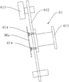
Fig. 3 is a schematic structural view of the stent of the present invention.
Detailed Description
In fig. 1, the arrow around the flowing water conveying platform 40 is the advancing direction of the mold, the arrow on the right side of the original sheet feeding platform is the conveying direction of the glass original sheet 90a, and the arrow on the left side of the finished product discharging platform is the conveying direction of the curved glass finished product 90b; wherein the mold stepping mechanism is shown in only one set and the remaining three sets are not shown.
As shown in fig. 1 to 3, the curved glass thermal forming system of the present invention includes a mold 80, a preheating mechanism 10, a forming mechanism 20, a cooling mechanism 30a, and a cooling mechanism 30b, wherein the mold includes an upper mold 80a and a lower mold 80b, the upper mold 80a and the lower mold 80b are respectively provided with a forming cavity surface matched with a curved glass product 90b, and further includes a flow conveying platform 40, a raw sheet feeding platform 50a, a finished product blanking platform 50b, a manipulator 60, and a mold moving mechanism 70;
the flow conveying platform 40 is used for bearing the mold, the original sheet feeding platform 50a is used for conveying glass original sheets 90a, and the finished product blanking platform 50b is used for conveying curved glass finished products 90b;
the manipulator 60 is used for opening the upper die 80a, loading the glass original sheet 90a on the original sheet feeding platform 50a into the lower die, and taking out the curved glass finished product 90b in the lower die and transferring the curved glass finished product to the finished product feeding platform 50 b;
the mold moving mechanism 70 includes four sets of mold stepping mechanisms and mold transposition mechanisms, the mold stepping mechanisms are distributed in a square shape and used for advancing operation of the molds, and the mold transposition mechanisms are provided with four sets of mold transposition mechanisms and respectively arranged at the corner positions where the adjacent mold stepping mechanisms intersect and used for changing the advancing direction of the molds;
the preheating mechanism 10, the molding mechanism 20 and the cooling mechanisms 30a, 30b are sequentially distributed on the flow conveying platform 40 along the advancing direction of the mold.
In this embodiment, the upper mold and the lower mold are made of graphite or ceramic.
In this embodiment, the water conveying platform 40 is composed of a platform 41, a platform 42, a platform 43 and a platform 44, wherein the platform 41, the platform 42, the platform 43 and the platform 44 may be an integral type or a split type.
In this embodiment, the mold stepping mechanism includes stepping pull rods 72, unit pull rods 74, electric cylinders 71 and swing cylinders 73, the stepping pull rods 72 of adjacent mold stepping mechanisms are perpendicular to each other, two ends of the stepping pull rods 72 are respectively connected with the output end of the electric cylinders 71 and the output end of the swing cylinders 73, the plurality of unit pull rods 74 are fixed on the stepping pull rods 72 at intervals and perpendicularly in the advancing direction of the mold, the swing cylinders 73 drive the stepping pull rods 72 to rotate, so that the unit pull rods 74 are inserted between the adjacent molds, then the electric cylinders drive the stepping pull rods to move forward, advancing operation of the mold is achieved, and resetting operations of the stepping pull rods 72 and the unit pull rods 74 are similar to each other.
In this embodiment, the mold indexing mechanism includes a pushing cylinder 75, and the pushing cylinder 75 pushes to change the traveling direction of the mold.
In this embodiment, the flowing water conveying platform 40 is provided with a sealed cabin enclosing the preheating mechanism 10, the forming mechanism 20 and the cooling mechanisms 30a and 30b, two ends of the sealed cabin in the advancing direction of the mold are respectively provided with an electric sliding door and communicated with a nitrogen supply device, and the sealed cabin is filled with nitrogen to prevent oxidation.
In this embodiment, the preheating mechanism 10 and the forming mechanism 20 are respectively provided with 4 sets, the cooling mechanisms 30a and 30b are provided with 7 sets, wherein the cooling mechanism 30a and the cooling mechanism 30b are only in different conveying directions, the forming temperature is 600 ℃ to 850 ℃, and the cooling temperature is 200 ℃. The preheating mechanism 10, the cooling mechanisms 30a and 30b and the forming mechanism 20 all comprise a press-fitting mechanism 21, an upper die heat transfer unit 22 and a lower die heat transfer unit 23, the upper die heat transfer unit 22 is connected to the output end of the lower portion of the press-fitting mechanism 21 and is arranged above the flowing water conveying platform 40, and the lower die heat transfer unit 23 is arranged at the bottom of the flowing water conveying platform 40. The mould 80 is conveyed to the position between the upper mould heat transfer unit and the lower mould heat transfer unit, the press-mounting mechanism drives the upper mould heat transfer unit to move downwards and abut against the upper mould, the mould is preheated and heated by the upper mould heat transfer unit 22 and the lower mould heat transfer unit 23, and when the forming temperature is reached, the press-mounting mechanism is further pressed downwards to complete the forming operation.
Specifically, taking a forming mechanism as an example, the press-fitting mechanism 21 includes a press-fitting cylinder 211, the press-fitting cylinder 211 is fixed on the upper platen 215 through a cylinder support 222, the upper platen 215 is disposed above the conveying platform in parallel, a piston rod of the press-fitting cylinder 211 is connected to the boom 214 through a universal joint 213, the upper mold heat transfer unit 22 includes an upper mold cooling plate 221, a heat insulation pad 222, and an upper mold heating plate 223, which are sequentially connected from top to bottom, the upper mold cooling plate is fixed at the lower end of the boom 214, the lower mold heat transfer unit 23 includes a lower mold heating plate, a lower mold heat insulation pad 232, and a lower mold cooling plate 233, which are sequentially connected from top to bottom, the lower mold cooling plate is fixed on the lower platen 234, the lower platen 234 is disposed below the conveying platform in parallel, the upper mold heating plate and the lower mold heating plate are respectively provided with a plurality of heating rods and a thermocouple, and the arrangement of the heat insulation pad and the heat insulation sleeve can prevent the external environment temperature from affecting the mold, thereby ensuring the forming quality.
The cooling mechanism differs from the forming mechanism in that the heating rod can be replaced by a cooling line.
In this embodiment, a bracket 61 and an air blowing device are connected to the robot arm 60. The bracket 61 comprises a bracket main body 612 with a cross structure, a connecting column 611 fixed at the center of the bracket main body, pneumatic suction cups 614 fixed at the two transverse sides of the bracket and a CCD probe 613 fixed at one longitudinal side of the bracket, the bracket is fixedly connected with the wrist of the manipulator 60 through a flange surface at the end part of the connecting column 611, the pneumatic suction cups are used for adsorbing the glass original sheet 90 a/curved glass finished product 90b, and the CCD probe is used for detecting the damage of the mold. The air blowing device comprises an air nozzle fixed on the wrist part of the mechanical wrist or the bracket main body, and the air nozzle is communicated with the air supply device and used for cleaning the surface of the molding cavity.
In this embodiment, the manipulator 60, the electric cylinder 71, the swing cylinder 73, the pushing cylinder 75, the electric sliding door, the pneumatic sucker, the CCD probe, the blowing device, the nitrogen supply device, the thermocouple and the heating rod are electrically connected to the PLC controller, respectively.
Claims (7)
1. Curved surface glass thermoforming system, it includes the mould, preheats mechanism, forming mechanism and cooling body, its characterized in that: the automatic sheet feeding device also comprises a flow conveying platform, a raw sheet feeding platform, a finished product discharging platform, a manipulator and a mould moving mechanism;
the water flow conveying platform is used for bearing a mold, the raw sheet feeding platform is used for conveying glass raw sheets, and the finished product feeding platform is used for conveying curved glass finished products;
the manipulator is used for loading the glass original sheet on the original sheet loading platform into the mold, and taking out the curved glass finished product in the mold and transferring the curved glass finished product to the finished product unloading platform;
the mould moving mechanism comprises a mould stepping mechanism and a mould transposition mechanism, the mould stepping mechanism is provided with four groups which are distributed in a square shape and used for the advancing operation of the mould, and the mould transposition mechanism is provided with four groups which are respectively arranged at the corner parts intersected by the adjacent mould stepping mechanisms and used for changing the advancing direction of the mould;
the preheating mechanism, the forming mechanism and the cooling mechanism are sequentially distributed on the running water conveying platform along the advancing direction of the die;
the mould stepping mechanisms comprise stepping pull rods, unit pull rods, electric cylinders and swing cylinders, the stepping pull rods of the adjacent mould stepping mechanisms are perpendicular to each other, two ends of each stepping pull rod are respectively connected with the output end of each electric cylinder and the output end of each swing cylinder, and the plurality of unit pull rods are fixed on the stepping pull rods at intervals and perpendicularly along the advancing direction of the mould; the mould transposition mechanism comprises a pushing cylinder.
2. The curved glass thermoforming system of claim 1, wherein: the flowing water conveying platform is provided with a sealing cabin which encloses the preheating mechanism, the forming mechanism and the cooling mechanism, and two ends of the sealing cabin, which are positioned in the advancing direction of the die, are respectively provided with an electric sliding door and communicated with a nitrogen supply device.
3. The curved glass thermoforming system of claim 1, wherein: the preheating mechanism, the forming mechanism and the cooling mechanism respectively comprise a press-fitting mechanism, an upper die heat transfer unit and a lower die heat transfer unit, the upper die heat transfer unit is connected to the output end of the press-fitting mechanism and arranged above the running water conveying platform, and the lower die heat transfer unit is arranged at the bottom of the running water conveying platform.
4. The curved glass thermoforming system of claim 3, wherein: the press-fitting mechanism comprises a press-fitting cylinder, the press-fitting cylinder is fixed on an upper platen, the upper platen is arranged above the conveying platform in parallel, a piston rod of the press-fitting cylinder is connected with a suspender through a universal joint, the upper die heat transfer unit comprises an upper die cooling plate, a heat insulation pad and an upper die heating plate which are sequentially connected from top to bottom, the upper die cooling plate is fixed at the lower end of the suspender, the lower die heat transfer unit comprises a lower die heating plate, a lower die heat insulation pad and a lower die cooling plate which are sequentially connected from top to bottom, and the upper die heating plate and the lower die heating plate are respectively provided with a plurality of heating rods and a thermocouple which are distributed along a plate body.
5. The curved glass thermoforming system of claim 1, wherein: the preheating mechanism and the forming mechanism are respectively provided with 4 groups, and the cooling mechanism is provided with 7 groups.
6. The curved glass thermoforming system of claim 1, wherein: the manipulator is connected with a support and an air blowing device, and the support is provided with a sucker.
7. The curved glass thermoforming system of claim 6, wherein: the support is of a cross structure, pneumatic suckers are respectively arranged on the two transverse sides of the support, and CCD probes are arranged on one longitudinal side of the support.
Priority Applications (1)
| Application Number | Priority Date | Filing Date | Title |
|---|---|---|---|
| CN201611201053.5A CN106830644B (en) | 2016-12-22 | 2016-12-22 | Curved glass thermal forming system |
Applications Claiming Priority (1)
| Application Number | Priority Date | Filing Date | Title |
|---|---|---|---|
| CN201611201053.5A CN106830644B (en) | 2016-12-22 | 2016-12-22 | Curved glass thermal forming system |
Publications (2)
| Publication Number | Publication Date |
|---|---|
| CN106830644A CN106830644A (en) | 2017-06-13 |
| CN106830644B true CN106830644B (en) | 2022-12-23 |
Family
ID=59135150
Family Applications (1)
| Application Number | Title | Priority Date | Filing Date |
|---|---|---|---|
| CN201611201053.5A Active CN106830644B (en) | 2016-12-22 | 2016-12-22 | Curved glass thermal forming system |
Country Status (1)
| Country | Link |
|---|---|
| CN (1) | CN106830644B (en) |
Families Citing this family (9)
| Publication number | Priority date | Publication date | Assignee | Title |
|---|---|---|---|---|
| CN107253818A (en) * | 2017-08-12 | 2017-10-17 | 哈尔滨奥瑞德光电技术有限公司 | The upper heating plate level adjusting structure of hot-bending machine |
| CN107365059B (en) * | 2017-08-30 | 2023-06-27 | 东莞恩特贝斯智能技术有限公司 | Conveying device and method for curved glass forming of mobile terminal |
| CN107673595A (en) * | 2017-11-21 | 2018-02-09 | 深圳市震仪实业有限公司 | Glass heat bender |
| CN107777864B (en) * | 2017-12-08 | 2023-12-01 | 河北陆源科技有限公司 | Compression molding system for reworking the shape of a glazing |
| CN108164127A (en) * | 2018-02-26 | 2018-06-15 | 哈尔滨奥瑞德光电技术有限公司 | A kind of 3D heat-bending glass automatic production line |
| CN108585452A (en) * | 2018-05-09 | 2018-09-28 | 深圳市太平洋自动化设备有限公司 | Forming method, formation system and the 3D bend glasses of 3D bend glasses |
| CN109836033A (en) * | 2019-01-04 | 2019-06-04 | 秦皇岛博硕光电设备股份有限公司 | Hot air forming method, hot gas move molding machine and hot gas moves formation system |
| CN110963680B (en) * | 2019-12-28 | 2024-02-06 | 嘉兴市云达智能科技有限公司 | Curved glass cover plate production device and production method thereof |
| CN114867137B (en) * | 2022-07-05 | 2022-09-23 | 中国飞机强度研究所 | Complex curved surface large-gradient strong-time-varying thermal field simulation heating system for testing aerospace plane |
Citations (7)
| Publication number | Priority date | Publication date | Assignee | Title |
|---|---|---|---|---|
| CN87215429U (en) * | 1987-11-14 | 1988-09-14 | 李德奎 | Curred glass forming machine |
| JPH06305755A (en) * | 1993-03-03 | 1994-11-01 | Pilkington Glass Ltd | Method and device for bending glass pane |
| CN104098254A (en) * | 2014-06-11 | 2014-10-15 | 程金贤 | Glass traction pressing forming machine and forming process thereof |
| CN104326645A (en) * | 2014-10-24 | 2015-02-04 | 太仓市黄发记机械模具制造有限公司 | Jump station glass molding machine |
| CN204356223U (en) * | 2014-12-31 | 2015-05-27 | 华玻科技股份有限公司 | A kind of continuous full-automatic pot cover glass tempering furnace |
| CN105271654A (en) * | 2015-11-18 | 2016-01-27 | 广东拓捷科技股份有限公司 | Hot press molding device for bent glass |
| CN206408100U (en) * | 2016-12-22 | 2017-08-15 | 无锡市凯创自动化科技有限公司 | A kind of bend glass thermoforming system |
-
2016
- 2016-12-22 CN CN201611201053.5A patent/CN106830644B/en active Active
Patent Citations (7)
| Publication number | Priority date | Publication date | Assignee | Title |
|---|---|---|---|---|
| CN87215429U (en) * | 1987-11-14 | 1988-09-14 | 李德奎 | Curred glass forming machine |
| JPH06305755A (en) * | 1993-03-03 | 1994-11-01 | Pilkington Glass Ltd | Method and device for bending glass pane |
| CN104098254A (en) * | 2014-06-11 | 2014-10-15 | 程金贤 | Glass traction pressing forming machine and forming process thereof |
| CN104326645A (en) * | 2014-10-24 | 2015-02-04 | 太仓市黄发记机械模具制造有限公司 | Jump station glass molding machine |
| CN204356223U (en) * | 2014-12-31 | 2015-05-27 | 华玻科技股份有限公司 | A kind of continuous full-automatic pot cover glass tempering furnace |
| CN105271654A (en) * | 2015-11-18 | 2016-01-27 | 广东拓捷科技股份有限公司 | Hot press molding device for bent glass |
| CN206408100U (en) * | 2016-12-22 | 2017-08-15 | 无锡市凯创自动化科技有限公司 | A kind of bend glass thermoforming system |
Also Published As
| Publication number | Publication date |
|---|---|
| CN106830644A (en) | 2017-06-13 |
Similar Documents
| Publication | Publication Date | Title |
|---|---|---|
| CN106830644B (en) | Curved glass thermal forming system | |
| CN105195585B (en) | Heat stamping and shaping production line | |
| CN103920780A (en) | Automated hot-stamping production line | |
| CN103480728A (en) | Automatic liner bottom plate forming production line | |
| CN107473573A (en) | A curved surface forming processing equipment | |
| CN105776828A (en) | Hot bending machine | |
| CN110978463A (en) | Female mold forming machine and its technological process | |
| CN102173568A (en) | Method and device for bending glass plate | |
| CN105107903A (en) | Elevator door seal head automatic flanging production line and production method thereof | |
| CN104540330A (en) | Dual-shaft flexible circuit board reinforcing laminating machine | |
| CN107879606A (en) | High-temperature mold is transported automatically and handling equipment, 3D cover-plate glass highly-efficient processing systems and its processing method | |
| CN110757885A (en) | Hot press | |
| CN106003096A (en) | Substrate cooling conveying robot | |
| CN206408100U (en) | A kind of bend glass thermoforming system | |
| CN116787785A (en) | A dual-station multi-point riveting hot riveting equipment with single-point temperature control | |
| CN109987826B (en) | Glass mold transfer equipment and glass processing system comprising same | |
| CN202367750U (en) | Full-automatic manipulator capable of delivering independently | |
| CN203804006U (en) | Hot stamping automatic production line | |
| KR101629182B1 (en) | Resistance heating and feeding apparatus | |
| CN110406159B (en) | Multi-station automatic hot press | |
| CN210048652U (en) | Hot bending machine | |
| CN207240168U (en) | A kind of mould putting frame | |
| CN204173574U (en) | Automatic transporting registration device between a kind of LCD nation locking equipment | |
| CN115139516A (en) | Full-automatic forming equipment for 3D or special-shaped film line | |
| CN203007116U (en) | Moving type pneumatic turnover robot |
Legal Events
| Date | Code | Title | Description |
|---|---|---|---|
| PB01 | Publication | ||
| PB01 | Publication | ||
| SE01 | Entry into force of request for substantive examination | ||
| SE01 | Entry into force of request for substantive examination | ||
| GR01 | Patent grant | ||
| GR01 | Patent grant | ||
| TR01 | Transfer of patent right |
Effective date of registration: 20240507 Address after: 126 Xishan New Village, Liangxi District, Wuxi City, Jiangsu Province, 214000 Patentee after: Wuxi Pusa Power Technology Co.,Ltd. Country or region after: China Address before: 2F, No. 60, Wangzhuang Road, New District, Wuxi City, Jiangsu Province, 214000 Patentee before: WUXI KAICHUANG AUTOMATION TECHNOLOGY Co.,Ltd. Country or region before: China |
|
| TR01 | Transfer of patent right |