CN1068732C - Motor start-up circuit - Google Patents
Motor start-up circuit Download PDFInfo
- Publication number
- CN1068732C CN1068732C CN97110755A CN97110755A CN1068732C CN 1068732 C CN1068732 C CN 1068732C CN 97110755 A CN97110755 A CN 97110755A CN 97110755 A CN97110755 A CN 97110755A CN 1068732 C CN1068732 C CN 1068732C
- Authority
- CN
- China
- Prior art keywords
- resistance
- triac
- circuit
- motor
- thermistor
- Prior art date
- Legal status (The legal status is an assumption and is not a legal conclusion. Google has not performed a legal analysis and makes no representation as to the accuracy of the status listed.)
- Expired - Lifetime
Links
- 238000010438 heat treatment Methods 0.000 description 11
- 239000002699 waste material Substances 0.000 description 4
- 239000013256 coordination polymer Substances 0.000 description 3
- 238000005516 engineering process Methods 0.000 description 3
- 230000006698 induction Effects 0.000 description 2
- 238000000034 method Methods 0.000 description 2
- 230000005855 radiation Effects 0.000 description 2
- 241000220317 Rosa Species 0.000 description 1
- 230000033228 biological regulation Effects 0.000 description 1
- 230000007423 decrease Effects 0.000 description 1
- 238000004519 manufacturing process Methods 0.000 description 1
- 230000001915 proofreading effect Effects 0.000 description 1
- 238000011084 recovery Methods 0.000 description 1
- 230000000630 rising effect Effects 0.000 description 1
- 230000035945 sensitivity Effects 0.000 description 1
Images


Classifications
-
- H—ELECTRICITY
- H02—GENERATION; CONVERSION OR DISTRIBUTION OF ELECTRIC POWER
- H02P—CONTROL OR REGULATION OF ELECTRIC MOTORS, ELECTRIC GENERATORS OR DYNAMO-ELECTRIC CONVERTERS; CONTROLLING TRANSFORMERS, REACTORS OR CHOKE COILS
- H02P1/00—Arrangements for starting electric motors or dynamo-electric converters
- H02P1/16—Arrangements for starting electric motors or dynamo-electric converters for starting dynamo-electric motors or dynamo-electric converters
- H02P1/42—Arrangements for starting electric motors or dynamo-electric converters for starting dynamo-electric motors or dynamo-electric converters for starting an individual single-phase induction motor
Landscapes
- Engineering & Computer Science (AREA)
- Power Engineering (AREA)
- Motor And Converter Starters (AREA)
- Control Of Ac Motors In General (AREA)
- Thermistors And Varistors (AREA)
- Control Of Motors That Do Not Use Commutators (AREA)
- Protection Of Generators And Motors (AREA)
- Valve Device For Special Equipments (AREA)
- Control Of Eletrric Generators (AREA)
Abstract
A motor start-up circuit is incorporated in a motor-driving circuit provided with an auxiliary coil which operates during a start-up time of the motor and a main coil for a steady-state operation of the motor. The start-up circuit in one form has a start-up thermistor with positive temperature characteristic and a Triac switch connected in series with the auxiliary coil and a triac-controlling thermistor with positive temperature characteristic connected in parallel to the start-up thermistor, and one of the terminals of the triac-controlling thermistor is connected to the gate of the Triac switch. The start-up circuit in another form has a Triac switch connected in series with the auxiliary coil and a triac-controlling thermistor with positive temperature characteristic connected in parallel to the auxiliary coil and the Triac switch and one of the terminals of the triac-controlling thermistor is connected to the gate of the Triac switch. In both forms, the triac-controlling thermistor has resistance 300 - 3000 OMEGA at 25 DEG C and volume of 30 - 60 mm<3> and doubles its value of resistance at 25 DEG C at 70 - 125 DEG C.
Description
The present invention relates to a kind of motor start-up circuit, relate in particular to the characteristic and the technical parameter that are used in the thermistor that has positive temperature profile in the sort circuit.
Fig. 9 has described the motor drive circuit that a kind of prior art is used for motor 1 (such as the monocyclic-start induction motor that is used in refrigerator compressor), the main coil 3 when it is included in the ancillary coil 2 that works when motor 1 starts and is used in steady operation.The motor start-up circuit that is used in this motor drive circuit generally includes the thermistor 4 with positive temperature characterisitic (PTC), and thermistor 4 is cascaded with the ancillary coil 2 of motor start-up.
But the resistance of thermistor can't infinitely increase.As a result, even after motor 1 starts, some unwanted electric current continues to flow to ancillary coil 2 by PTC thermistor 4, has wasted the electric energy of certain wattage.
The Tokkai 6-339291 patent application of Japanese publication has disclosed solution to this problem to a certain extent.According to this method, as shown in Figure 1, for convenience, adopt identical as shown in Figure 9 label to represent identical or equivalent element among the figure, ancillary coil 2 not only with as the PTC thermistor 4 that starts (" starting the PTC thermistor ") is connected, but also connects with Triac switch 7 (being designated hereinafter simply as " triac ").Another thermistor (" triac control PTC thermistor ") 8 with positive temperature characterisitic is in parallel with startup PTC thermistor 4, and an end of this triac control PTC thermistor 8 is connected with the grid G of triac7.
Electric power when power supply 6 when motor start-up offers in the motor 1, triggering signal is provided to the grid G of triac7 by triac control PTC thermistor 8, make triac7 be in the galvanization state, and make the motor start-up electric current flow through ancillary coil 2 by starting PTC thermistor 4.After starting, motor 1 in a period of time,, thereby reduced electric current by ancillary coil 2 owing to PTC thermistor self-heating makes the resistance increase.Simultaneously, also increase, thereby the electric current that flows through the triac7 grid G is reduced and disconnect triac7 owing to self thermal radiation makes the resistance of triac control PTC thermistor 8.
Subsequently, very little electric current continues to flow through triac control PTC thermistor.But, because the thermal capacity of triac control PTC thermistor 8 can be done more much smallerly than the thermal capacity that starts PTC thermistor 4, so it is more much smaller than the situation of circuit shown in Figure 9 to make it remain on electric power required under the high temperature high resistance condition.
Yet, if motor start-up circuit shown in Figure 1 really is used in the motor start-up (excursion that ambient temperature allowed is-10 to+100 ℃) of refrigerator compressor, tend to so to appear in short time of regulation (such as, about 1-10 second) can't cut off the situation of electric current reliably.For example be used in when outdoor in winter, the heating time that triac control PTC thermistor 8 increases resistance by himself heating can be very long, and the electric energy of wasting owing to electric moter noise and startup can be very big.Electric current even meeting can't be cut off.
On the other hand, if under the hot conditions of being used in (for example in summer), perhaps be connected on the compressor or be used near the compressor place, so before motor start-up, triac control PTC thermistor 8 may be under the heating condition or reach heating condition, and normal actuating motor.
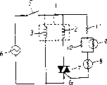
Disclose another kind of technology among the Tokkai patent application 7-123759 of Japanese publication, the time (" break time ") of cutting off the electric current that flows through ancillary coil is remained unchanged, and be not subjected to the influence of variation of ambient temperature.Figure 10 described according to this technology and adapted the motor drive circuit of motor start-up circuit.Among Figure 10, represent with identical label with element identical or equivalent among Fig. 9, and no longer repeat specification.
Shown in 10, according to this technology, triac7 connects with ancillary coil 2, and triac control PTC thermistor 8 links to each other with the grid of this triac7.This triac control PTC thermistor 8 is in parallel with correction thermistor 9 with positive temperature characterisitic and correction adjustment resistance 10, and this parallel circuits then links to each other with current-limiting resistance 11.In parallel with ancillary coil 2 and triac7 again by the series circuit that triac control PTC thermistor 8, parallel circuits and current-limiting resistance 11 are formed.
Adopt the motor start-up circuit of constructing like this, proofreading and correct parallel circuits that thermistor 9 and correction adjustment resistance 10 forms is used for variation according to ambient temperature and the electric current that flows through triac control PTC thermistor 8 is increased or reduces, thereby make thermal radiation controlled, and make keep constant the heating time of this triac control PTC thermistor 8.So, adopting this method, triac keeps the time length of conducting (ON) state thereby also is that the electric current that continues to flow through ancillary coil can be similar to and keeps constant, is not subjected to the influence of variation of ambient temperature.
The shortcoming of motor start-up circuit shown in Figure 10 is that it needs a large amount of components and parts.So, the cost height, and be difficult to make its miniaturization.Self-evident, a large amount of components and parts can produce the problem of its functional reliability.
In addition, if triac is used in the example shown in Fig. 1 and 10, so before electric current cuts off fully, depend on that the difference of grid sensitivity of the triac of triggering mode can cause the so-called half wave cycles shown in Figure 11 A and the 11B.If this half wave cycles oversize (for example above 3 seconds), motor can produce and clap noise (beatnoise) or beginning appearance fluctuation in it rotatablely moves so.
So, an object of the present invention is to provide a kind of improved motor start-up circuit that solves the prior art problem.
The present invention relates to a kind of motor start-up circuit that is used in motor drive circuit, it is included in the ancillary coil and the main coil that is used under the steady operation of work in the motor start-up time.
According to first kind of embodiment of the present invention, start-up circuit contains the startup thermistor of positive temperature characterisitic and the triac that connects with ancillary coil, and the triac control thermistor of the positive temperature characterisitic in parallel with starting thermistor, and a terminal of triac control thermistor is connected with the grid of triac.According to second kind of embodiment of the present invention, start-up circuit has the triac that connects with ancillary coil, and the positive temperature characterisitic triac control thermistor in parallel with ancillary coil and triac, and a terminal of triac control thermistor is connected with the grid of triac.According to any one this class embodiment of the present invention, triac control thermistor is at 25 ℃ of following and 30-60mm
3Volume under have the resistance of 300-3000 Ω, and double at 70-125 ℃ of following resistance.In the circuit of the foregoing description, can also introduce an additional resistance, the grid of triac and another terminal of triac grid the same side are coupled together.Specifically, triac control thermistor is at 25 ℃ and 30-50mm
3Volume under, should have the resistance of 1000-2000 Ω, and double at 85-110 ℃ of following resistance.Herein, the temperature that resistance doubles under 25 ℃ is referred to as " resistance doubles temperature ", and represents with symbol CP in the drawings.
According to the present invention,, thereby can prevent that the triac that occurs because of the grid current increase when voltage is big from leaking because triac control thermistor has the resistance value of 300-3000 Ω.And, even temperature also can make the triac operate as normal when low.
In addition, because the volume of triac control thermistor is 30 to 60mm
3, and CP is 70 to 125 ℃, so when temperature is higher, can prevent owing to lacking the motor internal driving operation that the turn-off time occurs.In addition, when temperature is low, can prevent that buzzing from appearring in motor.
And when the volume of thermistor be 30 to 50mm
3And CP is the resistance of 85 to 110 ℃ and thermistor when being 1000 to 2000 Ω, except above-mentioned advantage, can also reduce the consumption of power supply.
The same accompanying drawing that constitutes this specification part has been described embodiments of the invention, and they are used for illustrating principle of the present invention with specification.Among the figure:
Fig. 1 be according to first kind of embodiment adapted of the present invention the motor drive circuit figure of motor start-up circuit;
Fig. 2 is a circuit shown in Figure 1 when being used in ambient temperature and being 100 ℃, and it is 70 ℃ volume of triac control PTC thermistor 8 and the graph of a relation between opening time that resistance doubles temperature;
Fig. 3 is that circuit shown in Figure 1 is used in ambient temperature for-10 ℃ the time, and resistance doubles temperature at the volume of the control of the triac between 70 ℃ and 125 ℃ PTC thermistor and the graph of a relation between the half wave cycles;
Fig. 4 is a circuit shown in Figure 1 when being used in ambient temperature and being 100 ℃, and volume is 30mm
3The resistance of triac control PTC thermistor double temperature and the graph of a relation between opening time;
Fig. 5 is that circuit shown in Figure 1 is used in ambient temperature for-10 ℃ the time, and volume is 30-60mm
3The resistance of triac control PTC thermistor double graph of a relation between temperature and the half wave cycles;
Fig. 6 is the motor drive circuit figure that is furnished with another kind of motor start-up circuit according to second kind of embodiment of the present invention;
Fig. 7 is the motor drive circuit figure that is furnished with another motor start-up circuit according to the third embodiment of the present invention;
Fig. 8 is the motor drive circuit figure that is furnished with another motor start-up circuit according to the 4th kind of embodiment of the present invention;
Fig. 9 is the motor drive circuit figure that is furnished with the prior art motor start-up circuit;
Figure 10 is the motor drive circuit figure that is furnished with another kind of prior art motor start-up circuit;
What Figure 11 A and 11B described is to flow through the current waveform that is shown in the ancillary coil shown in Figure 10 and Fig. 1 respectively.
Among the figure, components and parts identical or equivalence at least are denoted by the same reference numerals, and do not do unnecessary repeat specification.
Although Fig. 1 is the structure that is used for describing the motor drive circuit of describing among the patent application 6-339291 of Japanese publication of being furnished with motor start-up circuit, it also represents the motor drive circuit of being furnished with according to the motor start-up circuit of first kind of embodiment of the present invention.But, feature according to circuit of the present invention shown in Figure 1 is that not only the triac control PTC thermistor 8 and the one terminal that include with starting 4 parallel connections of PTC thermistor link to each other with the grid G of triac7, and be at the resistance under 25 ℃ that between 300 and 3000 Ω its volume is between 30 and 60mm
3Between, and its resistance doubles temperature between 70-125 ℃.
When the switch 5 of this circuit is closed, electric current (" grid current ") will begin to flow to by triac control PTC thermistor 8 grid G of triac7.Triac control PTC thermistor 8 is under the normal temperature between 1 starting period at motor, and because its resistance is still very little, so grid current is connected even as big as making triac7.As a result, triac7 triggers once every half period, and the electric current of actuating motor 1 flows to ancillary coil 2 by starting PTC thermistor 4.Here suppose that motor 1 is a monocyclic-start induction motor.
After motor 1 has started, heated owing to start PTC thermistor 4, reduced so flow through the electric current of ancillary coil 2.Simultaneously, triac control PTC thermistor 8 also is heated, and make grid current very weak, thereby triac7 no longer is in conducting state.Owing to do not have electric current to flow through to start PTC thermistor 4 in this state, so, not only can avoid undesirable power wastage, and start PTC thermistor 4 and also be cooled, and its temperature drops to normal level very soon.
Subsequently, very weak electric current continues to flow through triac control PTC thermistor 8, still, because the volume of triac control PTC thermistor 8 has only 30-60mm
3, this is usually less than 1/5th of the volume that starts PTC thermistor 4, so waste of electric energy also can be reduced to less than 1/5th.In addition, motor 1 can being started once more also shortens required recovery time greatly.If in the scope of 300 to 3000 Ω, its volume restrictions is at 30-60mm with the resistance limits of 25 ℃ of following triac control PTC thermistors 8
3Scope in, and its resistance doubles temperature limitation in 70-125 ℃ scope, so, as long as ambient temperature remain on-10 and+100 ℃ scope in, the electric current that flows to ancillary coil 2 can be in the 1-10 time internal cutting off of second.
Above-mentioned restriction to the characteristic of triac control PTC thermistor 8 is then described below.
According to the present invention, the volume of triac control PTC thermistor 8 is in 30 and 60mm
3Between.The volume of triac control PTC thermistor 8 becomes positive correlation with its turn-off time, that is, volume is big more, and the turn-off time is long more.Fig. 2 has described the volume of triac control PTC thermistor 8 and the relation between the turn-off time, and here, when ambient temperature was 100 ℃ (upper limit of temperature range when this is to use), it was 70 ℃ that resistance doubles temperature.Generally speaking, temperature is higher, and heating process accelerates, and shorten heating time.What Fig. 2 described is because become opening time too short and motor 1 at volume less than 30mm
3And can't start the time, the volume that must make triac control PTC thermistor 8 under 100 ℃ is greater than 30mm
3
What Fig. 3 described is when ambient temperature is-10 ℃ (lower limit of temperature range during use), and half wave cycles is how to double temperature with the resistance of triac control PTC thermistor 8 to change during variation in the scope of 70 ℃ and 125 ℃.Increase with the increase of volume because heat the required time, so half wave cycles and volume also are positively related.Half wave cycles is elongated with the decline of ambient temperature.Under-10 ℃, if the volume of triac control PTC thermistor 8 surpasses 60mm
3, half wave cycles will become oversize so, and motor will produce bat noise and fluctuation in it rotatablely moves.
Here it is why the volume of triac control PTC thermistor 8 be selected at cause in the scope of 30-60mm.But, because waste of electric energy increases with the volume that triac controls PTC thermistor 8, so preferred range is 30-50mm
3
According to the present invention, the resistance of triac control PTC thermistor 8 doubles temperature value in 70-125 ℃ scope.Because using more, high resistance doubles the PTC thermistor 8 heating needs of temperature value than the long time, so the resistance of PTC thermistor doubles temperature and becomes positive correlation with heating time.What Fig. 4 described is that volume is 30mm
3Triac control PTC thermistor 8 when ambient temperature is 100 ℃, resistance doubles temperature and the relation between the turn-off time.In general, shorten with the rising of ambient temperature heating time.As shown in Figure 4, when ambient temperature was 100 ℃, the turn-off time became too short, and motor 1 can't start, unless the resistance of triac control PTC thermistor doubles temperature greater than 70 ℃.
What Fig. 5 described is that volume is 30mm when ambient temperature is-10 ℃
3To 60mm
3The resistance of PTC thermistor double relation between temperature and the half wave cycles.Resistance doubles to become positive correlation between temperature and the half wave cycles, still, and as shown in Figure 5, when ambient temperature is-10 ℃, surpass 125 ℃ if the resistance of PTC thermistor doubles temperature, then half wave cycles becomes too short, and motor produces bat noise and fluctuation in rotatablely moving.
In sum, the resistance of triac being controlled PTC thermistor 8 doubles in the scope that temperature is chosen in 70-125 ℃.Become big because waste of electric energy doubles increasing of temperature with resistance, be preferably lower than 110 ℃ so resistance doubles temperature.
From practice, not only the resistance of triac control PTC thermistor 8 doubles temperature and volume has fluctuation, and ambient temperature and source power supply all fluctuation can occur.So, be 70 ℃ if the resistance of PTC thermistor doubles temperature, and its volume is 30mm
3Even Fig. 2 shows owing to a certain little fluctuation, variation clearly also can appear in the turn-off time.This can make the startup of motor break down.Consider this possibility, the resistance of triac control PTC thermistor 8 doubles temperature and preferably is higher than 85 ℃.
The condition that is in 300-3000 Ω at the resistance of 25 ℃ of following triac control PTC thermistors 8 is discussed below.After the volume of having selected triac control PTC thermistor 8 as mentioned above and resistance double temperature, if at the resistance of 25 ℃ of following PTC thermistors 8 less than 300 Ω, when the voltage of source power supply 6 was higher, it is too big that grid current becomes, and can damage triac7 so so.On the other hand, if greater than 3000 Ω, when the voltage of power supply 6 hanged down, a little less than grid current became too, triac7 can can't connect, particularly under low ambient temperature so.
In sum, under 25 ℃, select the PTC thermistor of resistance between 300 Ω and 3000 Ω.Because can increase at 25 ℃ of following resistance, waste of electric energy is tending towards reducing, so preferably be chosen in the triac control PTC thermistor 8 of 25 ℃ of following resistance greater than 1000 Ω.Has 30-60mm in production
3When the triac of volume controlled the PTC thermistor, the viewpoint from restriction (for example resistivity and shape) preferably made its resistance under 25 ℃ be not more than 2000 Ω.
Selected like this after the volume under 25 ℃, resistance double temperature and resistance, even adopt a spot of element, also can be in the normal start-up time of motor (be generally 1-10 second), cut off the electric current that flows to ancillary coil 2 reliably, and be in ambient temperature-10 and+100 ℃ between the time, under all conditions, half wave cycles is reduced.
What Fig. 6 described is the motor drive circuit that is assembled with the another kind of start-up circuit of implementing present embodiment, among the figure, adopted with Fig. 1 in identical label represent identical or equivalent element.Circuit shown in Figure 6 is characterized in that triac7 connects with ancillary coil 2, and triac control PTC thermistor 8 is in parallel with the series circuit that ancillary coil 2 and triac7 form, and a terminal of this triac control PTC thermistor 8 links to each other with the grid of triac7.Employed triac control PTC thermistor 8 also satisfies following condition in this example, that is, under 25 ℃ of temperature, resistance is 300-3000 Ω, and volume is 30-60mm
3, and its resistance to double temperature be 70-125 ℃.The advantage of second kind of embodiment of the present invention shown in Fig. 6 is, can save the startup PTC thermistor 4 shown in Fig. 1, so circuit can form with the element of smaller amounts.
What Fig. 7 described is to be assembled with the motor drive circuit of implementing another start-up circuit of the present invention, has adopted identical as shown in Figure 1 label to represent identical or equivalent element among the figure.Circuit shown in Fig. 7 and circuit difference shown in Figure 1 only are that additional resistance 13 is inserted between the grid and this grid one side another terminal of triac7.
Shown in Fig. 8 is to be assembled with the motor drive circuit of implementing another start-up circuit of the present invention, adopted among the figure with Fig. 6 or Fig. 7 in employed same numeral represent identical or equivalent element.The difference of circuit shown in Fig. 8 and circuit shown in Figure 6 only is to have inserted an additional resistance 13 between the grid of triac7 and another terminal of this grid one side.
The advantage of the circuit shown in Fig. 7 and Fig. 8 is, because one part of current flows to additional resistance 13 by triac control PTC thermistor 8, so reduced to flow to the electric current of grid G.This guarantees that with increase the threshold value (gate trigger current) that triac7 is connected is equivalent.So, to compare with the related circuit of this additional resistance 13 (shown in Fig. 1 or 6) not, the turn-off time becomes shorter.Thereby half wave cycles also shortens.As mentioned above, because additional resistance 13 is used for reducing grid current, so when the voltage of source power supply 6 rose, additional resistance 13 also was used for preventing the damage of triac7.
In other circuit, the resistance of triac control PTC thermistor 8 is being preferably under 25 ℃ between the 1000-2000 Ω, and its volume is 30-50mm
3, and its resistance to double temperature be 85-110 ℃.
Claims (8)
1. motor start-up circuit that is assembled in the motor drive circuit, has an ancillary coil in the described motor drive circuit, only working in the time of described ancillary coil at motor start-up, described motor drive circuit also has a main coil that is used for carrying out described motor steady operation, it is characterized in that described motor start-up circuit comprises:
Startup thermistor with positive temperature characterisitic, and the Triac switch of connecting with described ancillary coil; And
Have positive temperature characterisitic and the triac control thermistor in parallel with described startup thermistor, a terminal of described triac control thermistor links to each other with the gate terminal of described Triac switch, the resistance of described triac control thermistor under 25 ℃ is 300-3000 Ω, and volume is 30-60mm
3, and the resistance between 70-125 ℃ is two times at 25 ℃ of following resistance.
2. motor start-up circuit as claimed in claim 1 is characterized in that, it also comprises the additional resistance that another terminal with the described gate terminal of described Triac switch and the described gate terminal of described Triac switch the same side couples together.
3. motor start-up circuit as claimed in claim 1 is characterized in that, the resistance of described triac control thermistor under 25 ℃ is 1000-2000 Ω, and volume is 30-50mm
3, and the resistance between 85-110 ℃ is two times of 25 ℃ of following resistance.
4. motor start-up circuit as claimed in claim 2 is characterized in that, the resistance of described triac control thermistor under 25 ℃ is 1000-2000 Ω, and volume is 30-50mm
3, and the resistance between 85-110 ℃ is two times of 25 ℃ of following resistance.
5. motor start-up circuit that is assembled in the motor drive circuit, one ancillary coil is arranged in the described motor drive circuit, described ancillary coil only works in the time at motor start-up, described motor drive circuit also has a main coil that is used for carrying out described motor steady operation, it is characterized in that described motor start-up circuit comprises:
The Triac switch of connecting with described ancillary coil; And
Have positive temperature characterisitic and with the triac of described ancillary coil and described Triac switch in parallel control thermistor, a terminal of described triac control thermistor links to each other with the gate terminal of described Triac switch, the resistance of described triac control thermistor under 25 ℃ is 300-3000 Ω, and volume is 30-60mm
3, and the resistance between 70-125 ℃ is two times of 25 ℃ of following resistance.
6. motor start-up circuit as claimed in claim 5 is characterized in that, it also comprises the additional resistance that another terminal with the described gate terminal of described Triac switch and the extreme the same side of described Triac switch gate couples together.
7. motor start-up circuit as claimed in claim 5 is characterized in that, the resistance of described triac control thermistor under 25 ℃ is 1000-2000 Ω, and volume is 30-50mm
3, and the resistance between 85-110 ℃ is two times of 25 ℃ of following resistance.
8. motor start-up circuit as claimed in claim 6 is characterized in that, the resistance of described triac control thermistor under 25 ℃ is 1000-2000 Ω, and volume is 30-50mm
3, and the resistance between 85-110 ℃ is two times of 25 ℃ of following resistance.
Applications Claiming Priority (3)
| Application Number | Priority Date | Filing Date | Title |
|---|---|---|---|
| JP94117/1996 | 1996-04-16 | ||
| JP8094117A JPH09285168A (en) | 1996-04-16 | 1996-04-16 | Circuit for starting up motor |
| JP94117/96 | 1996-04-16 |
Publications (2)
| Publication Number | Publication Date |
|---|---|
| CN1168022A CN1168022A (en) | 1997-12-17 |
| CN1068732C true CN1068732C (en) | 2001-07-18 |
Family
ID=14101496
Family Applications (1)
| Application Number | Title | Priority Date | Filing Date |
|---|---|---|---|
| CN97110755A Expired - Lifetime CN1068732C (en) | 1996-04-16 | 1997-04-16 | Motor start-up circuit |
Country Status (9)
| Country | Link |
|---|---|
| US (1) | US5898289A (en) |
| EP (1) | EP0802621B1 (en) |
| JP (1) | JPH09285168A (en) |
| KR (1) | KR100255711B1 (en) |
| CN (1) | CN1068732C (en) |
| AT (1) | ATE181470T1 (en) |
| DE (1) | DE69700272T2 (en) |
| DK (1) | DK0802621T3 (en) |
| TW (1) | TW445697B (en) |
Cited By (1)
| Publication number | Priority date | Publication date | Assignee | Title |
|---|---|---|---|---|
| WO2011094980A1 (en) * | 2010-02-08 | 2011-08-11 | 杭州星帅尔电器有限公司 | Electronic starter for refrigeration compressor |
Families Citing this family (16)
| Publication number | Priority date | Publication date | Assignee | Title |
|---|---|---|---|---|
| US6122153A (en) * | 1999-03-15 | 2000-09-19 | Eaton Corporation | Temperature protection control for a motor starter |
| MY125213A (en) * | 1999-11-12 | 2006-07-31 | Lg Electronics Inc | "device and method for controlling supply of current and static capacitance to compressor" |
| JP3785366B2 (en) * | 1999-11-12 | 2006-06-14 | エルジー エレクトロニクス インコーポレーテッド | Apparatus and method for controlling supply of current and capacitance to a compressor |
| US7018416B2 (en) * | 2000-07-06 | 2006-03-28 | Zimmer Spine, Inc. | Bone implants and methods |
| US6570359B2 (en) | 2000-07-15 | 2003-05-27 | Umakant Dipa Dubhashi | Motor starting circuit |
| JP4097034B2 (en) * | 2004-02-24 | 2008-06-04 | 株式会社センサータ・テクノロジーズジャパン | Power saving motor starter |
| JP4792826B2 (en) * | 2004-07-23 | 2011-10-12 | 株式会社村田製作所 | Single-phase induction motor start-up circuit |
| CN1294694C (en) * | 2004-11-24 | 2007-01-10 | 常熟市天银机电有限公司 | Mutual-inductance contactless starter |
| AU2006300169A1 (en) * | 2005-10-07 | 2007-04-19 | Lg Electronics Inc. | Power saving type compressor and refrigerator with the same and method for controlling the same |
| DE102006021256A1 (en) | 2006-04-28 | 2007-11-08 | Danfoss Compressors Gmbh | Motor start circuit |
| DE102006034499A1 (en) | 2006-07-19 | 2008-01-31 | Danfoss Compressors Gmbh | Motor start circuit |
| DE102006053524B4 (en) | 2006-11-07 | 2011-05-26 | Danfoss Flensburg Gmbh | Motor start circuit |
| KR101322316B1 (en) * | 2007-05-10 | 2013-10-25 | 엘지전자 주식회사 | Starting control apparatus and method for refrigerator |
| KR101301518B1 (en) * | 2012-06-22 | 2013-09-04 | 김영준 | Motor starter circuit including sparkless switches and low-cost motor protections for three phase induction motors |
| CN102969945B (en) * | 2012-12-10 | 2015-07-15 | 森萨塔科技(常州)有限公司 | Positive temperature coefficient thermistor starter |
| CN104426429B (en) * | 2013-08-26 | 2019-10-18 | 森萨塔科技公司 | Positive temperature coefficient thermistor starter |
Citations (1)
| Publication number | Priority date | Publication date | Assignee | Title |
|---|---|---|---|---|
| JPS6339291A (en) * | 1986-08-04 | 1988-02-19 | Sony Corp | Satellite broadcasting receiver |
Family Cites Families (12)
| Publication number | Priority date | Publication date | Assignee | Title |
|---|---|---|---|---|
| DE1613734B2 (en) * | 1967-10-07 | 1971-12-02 | Danfoss A/S, Nordborg (Dänemark) | OVER-TEMPERATURE PROTECTION FOR THE WINDING OF AC MOTORS |
| US3544869A (en) * | 1968-12-30 | 1970-12-01 | Texas Instruments Inc | A.c. motor starting control circuit utilizing triggerable semiconductor switching device with thermistor in gating circuit |
| US3683250A (en) * | 1970-07-29 | 1972-08-08 | Ecc Corp | Timed induction motor start switch utilizing positive temperature coefficient thermistor and semi-conductor switching device |
| US3965392A (en) * | 1974-01-02 | 1976-06-22 | Sprague Electric Company | Motor start system with two dissimilar PTCR elements |
| US4267635A (en) * | 1976-05-03 | 1981-05-19 | Texas Instruments Incorporated | Method of making a solid state electrical switch |
| US4161681A (en) * | 1977-03-17 | 1979-07-17 | General Electric Company | Prime mover, method of operating such and circuit |
| DE3021689A1 (en) * | 1980-06-10 | 1981-12-17 | Metabowerke GmbH & Co, 7440 Nürtingen | OVERLOAD PROTECTION FOR THE ENGINE, ESPECIALLY AN ELECTRIC HAND TOOL |
| CA2085202C (en) * | 1992-03-24 | 1996-10-22 | Ricky L. Bunch | Positive temperature coefficient start winding protection |
| JPH05328767A (en) * | 1992-05-25 | 1993-12-10 | Murata Mfg Co Ltd | Starting circuit of single-phase ac induction motor |
| JP3272493B2 (en) * | 1992-12-05 | 2002-04-08 | 山田電機製造株式会社 | Starting device for single-phase induction motor |
| JPH06349603A (en) * | 1993-06-04 | 1994-12-22 | Murata Mfg Co Ltd | Positive characteristic thermistor for demagnetizing circuit |
| JP3292877B2 (en) * | 1993-10-25 | 2002-06-17 | 山田電機製造株式会社 | Starting device for single-phase induction motor |
-
1996
- 1996-04-16 JP JP8094117A patent/JPH09285168A/en active Pending
-
1997
- 1997-04-01 US US08/831,992 patent/US5898289A/en not_active Expired - Lifetime
- 1997-04-08 TW TW086104407A patent/TW445697B/en not_active IP Right Cessation
- 1997-04-14 EP EP97106099A patent/EP0802621B1/en not_active Expired - Lifetime
- 1997-04-14 DE DE69700272T patent/DE69700272T2/en not_active Expired - Lifetime
- 1997-04-14 AT AT97106099T patent/ATE181470T1/en active
- 1997-04-14 DK DK97106099T patent/DK0802621T3/en active
- 1997-04-16 CN CN97110755A patent/CN1068732C/en not_active Expired - Lifetime
- 1997-04-16 KR KR1019970013936A patent/KR100255711B1/en not_active Expired - Lifetime
Patent Citations (1)
| Publication number | Priority date | Publication date | Assignee | Title |
|---|---|---|---|---|
| JPS6339291A (en) * | 1986-08-04 | 1988-02-19 | Sony Corp | Satellite broadcasting receiver |
Cited By (1)
| Publication number | Priority date | Publication date | Assignee | Title |
|---|---|---|---|---|
| WO2011094980A1 (en) * | 2010-02-08 | 2011-08-11 | 杭州星帅尔电器有限公司 | Electronic starter for refrigeration compressor |
Also Published As
| Publication number | Publication date |
|---|---|
| DE69700272D1 (en) | 1999-07-22 |
| ATE181470T1 (en) | 1999-07-15 |
| DE69700272T2 (en) | 2000-01-05 |
| KR100255711B1 (en) | 2000-05-01 |
| JPH09285168A (en) | 1997-10-31 |
| EP0802621A1 (en) | 1997-10-22 |
| US5898289A (en) | 1999-04-27 |
| TW445697B (en) | 2001-07-11 |
| DK0802621T3 (en) | 1999-11-22 |
| CN1168022A (en) | 1997-12-17 |
| EP0802621B1 (en) | 1999-06-16 |
| KR970072623A (en) | 1997-11-07 |
Similar Documents
| Publication | Publication Date | Title |
|---|---|---|
| CN1068732C (en) | Motor start-up circuit | |
| EP1683398B2 (en) | Thermal protection for lamp ballasts | |
| US5708330A (en) | Resonant voltage-multiplication, current-regulating and ignition circuit for a fluorescent lamp | |
| CN1337143A (en) | Ballast circuit | |
| WO2011127009A2 (en) | Method of striking a lamp in an electronic dimming ballast circuit | |
| JP5154319B2 (en) | Ceramic glow plug heating method and glow plug control device | |
| US20050151485A1 (en) | Method of soft-starting a switching power supply having time-based pulse triggering control | |
| KR0120598Y1 (en) | High pressure discharge lamp with pulsed inverter operating circuit and method of operating a discharge lamp | |
| KR910009146B1 (en) | Apparatus for discharge lamp | |
| CN1199335C (en) | Power circuit and method | |
| CN1288941C (en) | A device for rapidly reaching maximum brightness for fluorescent lamps | |
| US8502475B2 (en) | Discharge lamp ballast with feedback current control during an electrode heating operation | |
| US6153983A (en) | Full wave electronic starter | |
| US20060152168A1 (en) | Resonant circuit for halogen lighting | |
| CN1297612A (en) | Device having variable-speed motor | |
| US6696791B2 (en) | Method for starting a discharge lamp | |
| CN1458814A (en) | Circuit device for operating discharge lamp | |
| JPH1131445A (en) | Switch device | |
| JP2985047B2 (en) | Power control circuit | |
| GB2147750A (en) | Lamp starting circuits | |
| US7812545B2 (en) | Circuit arrangement for controlling the operation of an electronic transformer | |
| KR20100031088A (en) | Method and circuit arrangement for increasing the dielectric strength of metal oxide transistors at low temperatures | |
| Gonthier et al. | Low-loss Electronic Starter for Single-Phase Compressors | |
| CN1750730A (en) | Soft starting electronic ballast | |
| WO1997011586A1 (en) | Method of regulating lamp current through a fluorescent lamp by pulse energizing a driving supply |
Legal Events
| Date | Code | Title | Description |
|---|---|---|---|
| C10 | Entry into substantive examination | ||
| SE01 | Entry into force of request for substantive examination | ||
| C06 | Publication | ||
| PB01 | Publication | ||
| C14 | Grant of patent or utility model | ||
| GR01 | Patent grant | ||
| CX01 | Expiry of patent term | ||
| CX01 | Expiry of patent term |
Granted publication date: 20010718 |