CN106908824B - Be applied to railway accurate positioning system - Google Patents
Be applied to railway accurate positioning system Download PDFInfo
- Publication number
- CN106908824B CN106908824B CN201710253689.2A CN201710253689A CN106908824B CN 106908824 B CN106908824 B CN 106908824B CN 201710253689 A CN201710253689 A CN 201710253689A CN 106908824 B CN106908824 B CN 106908824B
- Authority
- CN
- China
- Prior art keywords
- module
- gnss
- conversion unit
- station module
- mobile station
- Prior art date
- Legal status (The legal status is an assumption and is not a legal conclusion. Google has not performed a legal analysis and makes no representation as to the accuracy of the status listed.)
- Active
Links
- 238000006243 chemical reaction Methods 0.000 claims abstract description 41
- 238000012545 processing Methods 0.000 claims abstract description 27
- 238000012544 monitoring process Methods 0.000 claims abstract description 23
- 230000005540 biological transmission Effects 0.000 claims abstract description 21
- QVFWZNCVPCJQOP-UHFFFAOYSA-N chloralodol Chemical compound CC(O)(C)CC(C)OC(O)C(Cl)(Cl)Cl QVFWZNCVPCJQOP-UHFFFAOYSA-N 0.000 claims description 16
- 238000011161 development Methods 0.000 abstract description 5
- 238000010586 diagram Methods 0.000 description 6
- XEEYBQQBJWHFJM-UHFFFAOYSA-N Iron Chemical compound [Fe] XEEYBQQBJWHFJM-UHFFFAOYSA-N 0.000 description 4
- 230000004913 activation Effects 0.000 description 2
- 229910052742 iron Inorganic materials 0.000 description 2
- 230000003137 locomotive effect Effects 0.000 description 2
- 230000009286 beneficial effect Effects 0.000 description 1
- 238000004891 communication Methods 0.000 description 1
- 238000012937 correction Methods 0.000 description 1
- 230000007547 defect Effects 0.000 description 1
- 230000002349 favourable effect Effects 0.000 description 1
- 238000012986 modification Methods 0.000 description 1
- 230000004048 modification Effects 0.000 description 1
- 230000006855 networking Effects 0.000 description 1
- 230000005855 radiation Effects 0.000 description 1
- 238000012827 research and development Methods 0.000 description 1
- 238000012876 topography Methods 0.000 description 1
Images


Classifications
-
- G—PHYSICS
- G01—MEASURING; TESTING
- G01S—RADIO DIRECTION-FINDING; RADIO NAVIGATION; DETERMINING DISTANCE OR VELOCITY BY USE OF RADIO WAVES; LOCATING OR PRESENCE-DETECTING BY USE OF THE REFLECTION OR RERADIATION OF RADIO WAVES; ANALOGOUS ARRANGEMENTS USING OTHER WAVES
- G01S19/00—Satellite radio beacon positioning systems; Determining position, velocity or attitude using signals transmitted by such systems
- G01S19/38—Determining a navigation solution using signals transmitted by a satellite radio beacon positioning system
- G01S19/39—Determining a navigation solution using signals transmitted by a satellite radio beacon positioning system the satellite radio beacon positioning system transmitting time-stamped messages, e.g. GPS [Global Positioning System], GLONASS [Global Orbiting Navigation Satellite System] or GALILEO
- G01S19/42—Determining position
- G01S19/50—Determining position whereby the position solution is constrained to lie upon a particular curve or surface, e.g. for locomotives on railway tracks
-
- G—PHYSICS
- G01—MEASURING; TESTING
- G01S—RADIO DIRECTION-FINDING; RADIO NAVIGATION; DETERMINING DISTANCE OR VELOCITY BY USE OF RADIO WAVES; LOCATING OR PRESENCE-DETECTING BY USE OF THE REFLECTION OR RERADIATION OF RADIO WAVES; ANALOGOUS ARRANGEMENTS USING OTHER WAVES
- G01S19/00—Satellite radio beacon positioning systems; Determining position, velocity or attitude using signals transmitted by such systems
- G01S19/01—Satellite radio beacon positioning systems transmitting time-stamped messages, e.g. GPS [Global Positioning System], GLONASS [Global Orbiting Navigation Satellite System] or GALILEO
- G01S19/13—Receivers
- G01S19/34—Power consumption
-
- G—PHYSICS
- G01—MEASURING; TESTING
- G01S—RADIO DIRECTION-FINDING; RADIO NAVIGATION; DETERMINING DISTANCE OR VELOCITY BY USE OF RADIO WAVES; LOCATING OR PRESENCE-DETECTING BY USE OF THE REFLECTION OR RERADIATION OF RADIO WAVES; ANALOGOUS ARRANGEMENTS USING OTHER WAVES
- G01S19/00—Satellite radio beacon positioning systems; Determining position, velocity or attitude using signals transmitted by such systems
- G01S19/38—Determining a navigation solution using signals transmitted by a satellite radio beacon positioning system
- G01S19/39—Determining a navigation solution using signals transmitted by a satellite radio beacon positioning system the satellite radio beacon positioning system transmitting time-stamped messages, e.g. GPS [Global Positioning System], GLONASS [Global Orbiting Navigation Satellite System] or GALILEO
- G01S19/42—Determining position
- G01S19/43—Determining position using carrier phase measurements, e.g. kinematic positioning; using long or short baseline interferometry
-
- Y—GENERAL TAGGING OF NEW TECHNOLOGICAL DEVELOPMENTS; GENERAL TAGGING OF CROSS-SECTIONAL TECHNOLOGIES SPANNING OVER SEVERAL SECTIONS OF THE IPC; TECHNICAL SUBJECTS COVERED BY FORMER USPC CROSS-REFERENCE ART COLLECTIONS [XRACs] AND DIGESTS
- Y02—TECHNOLOGIES OR APPLICATIONS FOR MITIGATION OR ADAPTATION AGAINST CLIMATE CHANGE
- Y02D—CLIMATE CHANGE MITIGATION TECHNOLOGIES IN INFORMATION AND COMMUNICATION TECHNOLOGIES [ICT], I.E. INFORMATION AND COMMUNICATION TECHNOLOGIES AIMING AT THE REDUCTION OF THEIR OWN ENERGY USE
- Y02D30/00—Reducing energy consumption in communication networks
- Y02D30/70—Reducing energy consumption in communication networks in wireless communication networks
Landscapes
- Engineering & Computer Science (AREA)
- Radar, Positioning & Navigation (AREA)
- Remote Sensing (AREA)
- Computer Networks & Wireless Communication (AREA)
- Physics & Mathematics (AREA)
- General Physics & Mathematics (AREA)
- Position Fixing By Use Of Radio Waves (AREA)
Abstract
The invention discloses a precise positioning system applied to railways, and relates to the technical field of railways. The system comprises a reference station module, a mobile station module, a transmission module and a processing module, wherein the reference station module comprises a power supply conversion unit, a first GNSS positioning unit, a GNSS antenna and a level conversion unit, the reference station module is connected to the mobile station module through the transmission module, the mobile station module comprises a power supply conversion unit, a second GNSS positioning unit, the GNSS antenna and the level conversion unit, and the reference station module is connected to the processing module through the transmission module. After the scheme is adopted, the development cost of the railway positioning system can be reduced, the monitoring range is enlarged, the 360-degree dead angle-free and dead zone-free monitoring and positioning are realized, the positioning accuracy is improved, and the safe and stable operation of the railway transportation system is ensured.
Description
Technical Field
The invention relates to the technical field of railways, in particular to a precise positioning system applied to railways.
Background
Along with the development of the economy in China, the railway transportation industry is developed more and more, great convenience is provided for the daily life traveling of people, however, along with the increasing railway transportation, the current railway positioning system is high in cost, limited in monitoring range and multiple in blind areas, the monitoring system is easily affected by the current environment to cause inaccurate monitoring positioning positions, misjudgment of the system is easily caused, and unnecessary trouble is caused to the railway transportation system.
Disclosure of Invention
Aiming at the defects of the prior art, the invention provides the accurate positioning system applied to the railway, which can reduce the development cost of the railway positioning system, enlarge the monitoring range, realize 360-degree dead-angle-free and dead-zone-free monitoring positioning, improve the positioning accuracy and ensure the safe and stable operation of the railway transportation system.
In order to solve the technical problems, the invention adopts the following technical scheme: a precision positioning system for a railway, comprising: the reference station module comprises a power conversion unit, a first GNSS positioning unit, a GNSS antenna and a level conversion unit, wherein the power conversion unit is connected with the first GNSS positioning unit, the level conversion unit is connected with the first GNSS positioning unit, the GNSS antenna is connected with the first GNSS positioning unit, the reference station module is connected to the mobile station module through the transmission module, the mobile station module comprises a power conversion unit, a second GNSS positioning unit, the GNSS antenna and the level conversion unit, the power conversion unit is connected with the second GNSS positioning unit, the level conversion unit is connected with the second GNSS positioning unit, the GNSS antenna is connected to the second GNSS positioning unit, the reference station module is connected to the processing module through the transmission module, and the processing module is connected with the monitoring terminal.
As a further technical scheme, the first GNSS positioning unit includes a NEO-M8P-2 chip.
As a further technical scheme, the second GNSS positioning unit comprises a NEO-M8P-0 chip.
As a further technical scheme, the transmission module comprises a LoRaWAN network, and the LoRaWAN network comprises a LoRa gateway module and a plurality of LoRa node modules.
As a further technical scheme, the reference station module is connected with the LoRa gateway module, the mobile station module is connected with the LoRa node modules, and the mobile station modules are multiple, and the LoRa node modules are correspondingly arranged with each mobile station module.
As a further technical scheme, the processing module comprises a data receiving server, a data control server and a data processing server, wherein the data receiving server is connected with the data control server, and the data control server is connected with the data processing server.
As a further technical scheme, the monitoring terminal is a PC intelligent terminal, and a plurality of PC intelligent terminals are provided.
As a further technical scheme, the level conversion unit is a MAX3232 level converter, and the MAX3232 level converter is connected with the processing module through a serial port.
The beneficial effects of adopting above-mentioned technical scheme to produce lie in: the invention can reduce the development cost of the railway positioning system, enlarge the monitoring range, realize 360-degree dead-angle-free and dead-zone-free monitoring positioning, improve the positioning accuracy and ensure the safe and stable operation of the railway transportation system by providing the accurate positioning system applied to the railway.
Drawings
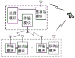
FIG. 1 is a block diagram of the main structure of one embodiment of the present invention;
FIG. 2 is a schematic diagram of a reference station module according to one embodiment of the invention;
FIG. 3 is a schematic diagram of a mobile station module according to one embodiment of the invention;
fig. 4 is a block diagram of another embodiment of the present invention.
Detailed Description
The invention will be described in further detail with reference to the drawings and the detailed description.
As shown in fig. 1, an embodiment of a precise positioning system for a railway according to the present invention includes: the reference station module comprises a power conversion unit, a first GNSS positioning unit, a GNSS antenna and a level conversion unit, wherein the power conversion unit is connected with the first GNSS positioning unit, the level conversion unit is connected with the first GNSS positioning unit, the GNSS antenna is connected with the first GNSS positioning unit, the reference station module is connected to the mobile station module through the transmission module, the mobile station module comprises a power conversion unit, a second GNSS positioning unit, the GNSS antenna and the level conversion unit, the power conversion unit is connected with the second GNSS positioning unit, the level conversion unit is connected with the second GNSS positioning unit, the GNSS antenna is connected to the second GNSS positioning unit, the reference station module is connected to the processing module through the transmission module, and the processing module is connected with the monitoring terminal.
In order to meet the positioning precision requirement, a carrier phase observation value real-time dynamic positioning technology is required to be used, a three-dimensional positioning result of a measuring station in a designated coordinate system can be provided in real time, and the centimeter-level precision is achieved.
The GNSS antenna is a GPS/GLONASS compatible antenna, and is used as a transmitting antenna of an on-channel forwarding system and also can be used as a receiving antenna of a GPS navigation and positioning system. The antenna is in the form of a microstrip. The directivity pattern essentially achieves hemispherical radiation. The antenna is composed of a radome, a microstrip radiator, a bottom plate, a high-frequency output socket and the like, and has the advantages of simple structure, small volume and convenient use in cooperation with a tripod.
The mobile station module adopts a common positioning receiver, the mobile station module only can correctly report pseudo-range information, carrier phase information and position information, the positioning accuracy of the mobile station module cannot influence the positioning result calculated by the processing module, and the mobile station module is used for receiving satellite signals of the same satellite of the reference station module and reporting original observed quantity information to the processing module; in order to save power consumption, the receiver of the mobile station module is in a dormant state at ordinary times, activated once at intervals, and the activation time is set independently according to requirements, for example, the activation time is activated once every 15 minutes in the embodiment, after positioning is successful, the pseudo range, carrier phase information and position information are reported to the control module, after the positioning is successful, the user machine closes the satellite receiving channel, enters the dormant state, and the mobile station module is arranged on the mobile devices such as locomotives, personnel and iron shoes to monitor the positioning pseudo range, the carrier phase information and the position information.
The first GNSS positioning unit comprises a NEO-M8P-2 chip and is used for realizing the function of accurately positioning satellite positions by the reference station.
The second GNSS positioning unit comprises a NEO-M8P-0 chip, the NEO-M8P-0 chip is used for realizing the functions of the mobile station module, an RTCM (radio technical commission maritime service) protocol is used for receiving the error correction number of the base station receiver NEO-M8P-2 from u-blox through a data communication link, the centimeter-level positioning precision can be realized, and the NEO-M8P module is used for greatly reducing research and development work, directly integrating the module into a system or integrating the module into an existing product platform.
Referring to fig. 2, a reference station module schematic diagram of an embodiment of the present invention includes a power conversion unit, a first GNSS positioning unit, a GNSS antenna and a level conversion unit, where the power conversion unit is connected to the first GNSS positioning unit, the first GNSS positioning unit is connected to the level conversion unit, the first GNSS positioning unit is connected to the GNSS antenna, the reference station receiver converts external 5v dc power into 3.3v through the power conversion unit, and provides power to the first GNSS positioning unit, i.e. a high-precision positioning module NEO-M8P-2 chip, and the NEO-M8P-2 chip can receive GPS and beidou satellite signals after being externally connected to the GNSS antenna, and send the received original observed quantity information, pseudo range, carrier phase information and calculated position information to a processing module through a serial port RX232 for high-precision differential positioning.
As shown in fig. 3, a mobile station module according to an embodiment of the present invention is shown in the schematic diagram, the mobile station module includes a power conversion unit, a second GNSS positioning unit, a GNSS antenna and a level conversion unit, the power conversion unit is connected to the second GNSS positioning unit, the second GNSS positioning unit is connected to the level conversion unit, the GNSS antenna is connected to the second GNSS positioning unit, the mobile station module receiver converts external 5v dc power into 3.3v through the power conversion chip, provides power to the high-precision positioning module NEO-M8P-0 and the wireless transmission module SX-1278, the NEO-M8P-0 can only be used as a mobile station, the NEO-M8P-0 can receive GPS satellite signals and beidou satellite signals after being connected to the GNSS antenna through the serial port RX232, the received original observed quantity information, the pseudo range, carrier phase information and the resolved position information are transmitted to the wireless transmission module SX-1278, the SX-8 external antenna through the established wireless network, and the data transmission system in the reference station module transmits these information to the data transmission system through the serial port RS232, so as to differential the high-precision positioning module.
The processing module comprises a data receiving server, a data control server and a data processing server, wherein a PC platform is selected, the data receiving server is connected with the data control server, the data control server is connected with the data processing server, the data receiving server is used for receiving positioning pseudo-range, carrier phase information and position information of satellite positioning sent by the mobile station module and the reference station module, the data control server and the data processing server are used for controlling and processing data received by the data receiving server, ephemeris information, position information and original observed quantity information reported by the reference station module and each mobile station module are received through a serial port and a wireless data transmission link, the accurate position of each mobile station module is calculated through a differential algorithm, the accurate position of each positioning object is accurately calculated, and the accurate position is transmitted to the monitoring terminal, so that staff in each monitoring room can conveniently check.
As shown in FIG. 4, the transmission module comprises a LoRaWAN network, the LoRaWAN network comprises a LoRa gateway module and a plurality of LoRa node modules, the plurality of mobile station modules are arranged corresponding to each mobile station module, star networking is realized, the furthest transmission distance of the nodes is far more than 1Km, the transmission power and the transmission rate are adjustable, the system power consumption requirement can be met, each LoRa node module is connected with one mobile station module for transmitting the positioning information of an object collected by the mobile station module, the information collected by each mobile station module is uniformly transmitted to the LoRa gateway module through the LoRa node modules, and is transmitted to the reference station module after being summarized through the LoRa gateway modules.
Specifically, in this embodiment, a lorewan gateway is disposed on the reference station module, and meanwhile, lorewan network nodes are disposed on the mobile stations (locomotives, personnel and iron shoes) respectively, so as to form the lorewan network. The data of each mobile station module is sent to the gateway module of the reference station module through the node module, and the reference station module obtains the data of the mobile station module and then sends the data to the processing module through the serial port.
The monitoring terminals are PC intelligent terminals, a plurality of the monitoring terminals are respectively located in different monitoring rooms, so that monitoring personnel can conveniently monitor the positioning of each object in the railway system in different monitoring rooms, and the safe and stable operation of the system is ensured.
The level conversion unit is a MAX3232 level converter, and the MAX3232 level converter is connected with the processing module through a serial port.
The high-precision receiver of the reference station module is used for receiving satellite signals and selecting a dual-mode and dual-frequency receiver, and can receive GPS L1/L2 and BDS B1/B3.
The positioning of the reference station receiver is required to satisfy the following conditions: the reference station should have the correct known coordinates; the reference station is selected from the positions which have higher topography, wider sky, no obstacle with the surrounding altitude exceeding 15 degrees and are favorable for receiving satellite signals and receiving and transmitting data chains; no interference of an interference source; the positioning accuracy index of the positioning receiver is as follows: common: 1.5m, RTK:3cm.
After the scheme is adopted, the development cost of the railway positioning system can be reduced, the monitoring range is enlarged, the 360-degree dead angle-free and dead zone-free monitoring and positioning are realized, the positioning accuracy is improved, and the safe and stable operation of the railway transportation system is ensured.
The foregoing description of the preferred embodiments of the invention is not intended to be limiting, but rather is intended to cover all modifications, equivalents, and alternatives falling within the spirit and principles of the invention.
Claims (6)
1. Be applied to accurate positioning system of railway, characterized by includes: the system comprises a reference station module, a mobile station module, a transmission module and a processing module, wherein the reference station module comprises a power supply conversion unit, a first GNSS positioning unit, a GNSS antenna and a level conversion unit, the power supply conversion unit is connected with the first GNSS positioning unit, the first GNSS positioning unit is connected with the level conversion unit, the first GNSS positioning unit is connected with the GNSS antenna, the reference station module is connected to the mobile station module through the transmission module, the mobile station module comprises a power supply conversion unit, a second GNSS positioning unit, the GNSS antenna and the level conversion unit, the power supply conversion unit is connected with the second GNSS positioning unit, the second GNSS positioning unit is connected with the level conversion unit, the GNSS antenna is connected with the second GNSS positioning unit, the reference station module is connected with the processing module through the transmission module, and the processing module is connected with a monitoring terminal; the transmission module comprises a LoRaWAN network, wherein the LoRaWAN network comprises a LoRa gateway module and a plurality of LoRa node modules; the processing module comprises a data receiving server, a data control server and a data processing server, wherein the data receiving server is connected with the data control server, and the data control server is connected with the data processing server.
2. The precise positioning system for railways of claim 1, wherein the first GNSS positioning unit comprises a NEO-M8P-2 chip.
3. The precise positioning system for railways of claim 1, wherein the second GNSS positioning unit comprises a NEO-M8P-0 chip.
4. The precise positioning system for railways of claim 1, wherein the reference station module is connected to a LoRa gateway module, the mobile station module is connected to a LoRa node module, and a plurality of mobile station modules are provided, wherein the LoRa node module is provided corresponding to each mobile station module.
5. The precise positioning system for the railway according to claim 1, wherein the monitoring terminals are PC intelligent terminals, and a plurality of PC intelligent terminals are provided.
6. The precise positioning system for railway according to claim 1, wherein the level conversion unit is a MAX3232 level converter, and the MAX3232 level converter is connected with the processing module through a serial port.
Priority Applications (1)
| Application Number | Priority Date | Filing Date | Title |
|---|---|---|---|
| CN201710253689.2A CN106908824B (en) | 2017-04-18 | 2017-04-18 | Be applied to railway accurate positioning system |
Applications Claiming Priority (1)
| Application Number | Priority Date | Filing Date | Title |
|---|---|---|---|
| CN201710253689.2A CN106908824B (en) | 2017-04-18 | 2017-04-18 | Be applied to railway accurate positioning system |
Publications (2)
| Publication Number | Publication Date |
|---|---|
| CN106908824A CN106908824A (en) | 2017-06-30 |
| CN106908824B true CN106908824B (en) | 2023-07-14 |
Family
ID=59209747
Family Applications (1)
| Application Number | Title | Priority Date | Filing Date |
|---|---|---|---|
| CN201710253689.2A Active CN106908824B (en) | 2017-04-18 | 2017-04-18 | Be applied to railway accurate positioning system |
Country Status (1)
| Country | Link |
|---|---|
| CN (1) | CN106908824B (en) |
Families Citing this family (10)
| Publication number | Priority date | Publication date | Assignee | Title |
|---|---|---|---|---|
| CN107360538B (en) * | 2017-07-06 | 2020-06-30 | 中国石油集团东方地球物理勘探有限责任公司 | Method for communication between intelligent devices and intelligent device |
| CN109842650A (en) * | 2017-11-27 | 2019-06-04 | 北京通号国铁城市轨道技术有限公司 | One kind interconnects train control system |
| CN108001477B (en) * | 2018-01-03 | 2024-02-13 | 伊军庆 | System and method for remotely monitoring and managing iron shoes |
| JP6949767B2 (en) * | 2018-03-22 | 2021-10-13 | 日立建機株式会社 | Worker management system |
| CN111221017A (en) * | 2020-02-18 | 2020-06-02 | 神华包神铁路有限责任公司 | Beidou positioning method for iron shoes |
| CN111708067B (en) * | 2020-08-04 | 2022-04-12 | 中国铁道科学研究院集团有限公司铁道建筑研究所 | Automatic guide system of excavator |
| CN112711049A (en) * | 2020-12-15 | 2021-04-27 | 国网北京市电力公司 | GPS |
| CN112994845B (en) * | 2021-02-08 | 2022-09-27 | 武汉梦芯科技有限公司 | RTK data transmission method, system and storage medium based on combination of LoRa and LDPC |
| CN113280911A (en) * | 2021-06-04 | 2021-08-20 | 西北大学 | Vibration multi-parameter intelligent acquisition system for heavy haul railway train |
| CN117092678B (en) * | 2023-10-18 | 2024-01-26 | 深圳市硕腾科技有限公司 | High-precision RTK positioning system based on LoRa |
Citations (5)
| Publication number | Priority date | Publication date | Assignee | Title |
|---|---|---|---|---|
| CN1473725A (en) * | 2003-07-23 | 2004-02-11 | 长春一汽启明信息技术有限公司 | Vehicle running recorder |
| CN201876547U (en) * | 2010-05-14 | 2011-06-22 | 中国科学院国家天文台 | Position monitoring system for simultaneously monitoring multiple positions in real time |
| WO2016065320A1 (en) * | 2014-10-24 | 2016-04-28 | Telogis, Inc. | System for performing vehicle diagnostic and prognostic analysis |
| CN205318164U (en) * | 2015-12-30 | 2016-06-15 | 首都师范大学 | Agricultural machinery's monitoring device and agricultural machinery |
| CN206657110U (en) * | 2017-04-18 | 2017-11-21 | 冯本勇 | A kind of precise positioning system applied to railway |
Family Cites Families (1)
| Publication number | Priority date | Publication date | Assignee | Title |
|---|---|---|---|---|
| US7855678B2 (en) * | 2007-05-16 | 2010-12-21 | Trimble Navigation Limited | Post-mission high accuracy position and orientation system |
-
2017
- 2017-04-18 CN CN201710253689.2A patent/CN106908824B/en active Active
Patent Citations (5)
| Publication number | Priority date | Publication date | Assignee | Title |
|---|---|---|---|---|
| CN1473725A (en) * | 2003-07-23 | 2004-02-11 | 长春一汽启明信息技术有限公司 | Vehicle running recorder |
| CN201876547U (en) * | 2010-05-14 | 2011-06-22 | 中国科学院国家天文台 | Position monitoring system for simultaneously monitoring multiple positions in real time |
| WO2016065320A1 (en) * | 2014-10-24 | 2016-04-28 | Telogis, Inc. | System for performing vehicle diagnostic and prognostic analysis |
| CN205318164U (en) * | 2015-12-30 | 2016-06-15 | 首都师范大学 | Agricultural machinery's monitoring device and agricultural machinery |
| CN206657110U (en) * | 2017-04-18 | 2017-11-21 | 冯本勇 | A kind of precise positioning system applied to railway |
Also Published As
| Publication number | Publication date |
|---|---|
| CN106908824A (en) | 2017-06-30 |
Similar Documents
| Publication | Publication Date | Title |
|---|---|---|
| CN106908824B (en) | Be applied to railway accurate positioning system | |
| CN109283565B (en) | Indoor and outdoor positioning system and method based on UWB fusion GPS and inertial navigation | |
| AU2012343109B2 (en) | Method and device for acquiring information about base station antenna, and base station antenna | |
| WO2020062531A1 (en) | Positioning device and positioning method therefor | |
| CN110244770A (en) | A kind of accurate landing system of unmanned plane based on UWB positioning | |
| CN109975758A (en) | Wi-Fi blue tooth integrated base station location system | |
| CN108333607A (en) | Mobile intelligent terminal differential position system based on CORS enhancings | |
| CN105607079A (en) | Method for positioning precision enhancement of GNSS, and GNSS positioning system | |
| CN111200869A (en) | Device and system integrating UWB single base station positioning and wireless data transmission | |
| CN201957248U (en) | Hybrid location system of mobile terminal | |
| CN105992156A (en) | Bluetooth technology-based mobile node positioning method | |
| CN206657110U (en) | A kind of precise positioning system applied to railway | |
| CN104717747A (en) | Moving coordinate accurate locating system | |
| CN110007323A (en) | A kind of intelligent interaction positioning system and its localization method | |
| CN106658712A (en) | Communication terminal positioning method system | |
| CN113466911A (en) | Beidou high-precision monitoring system and monitoring method | |
| CN109164475A (en) | Container monitoring method based on Beidou GPS positioning system | |
| CN105592167B (en) | A kind of base station electromagnetic radiation monitoring system | |
| CN207896964U (en) | A satellite differential positioning data transceiver terminal | |
| CN207078156U (en) | Point-to-train communication device | |
| CN219919180U (en) | An ultra-wideband positioning system including anomaly detection | |
| CN207457515U (en) | A kind of agricultural differential position system based on RTK | |
| CN212483875U (en) | RTK-based positioning equipment | |
| CN103517208A (en) | Intelligent electronic medical guidance system | |
| CN205507098U (en) | Little volume orientation module |
Legal Events
| Date | Code | Title | Description |
|---|---|---|---|
| PB01 | Publication | ||
| PB01 | Publication | ||
| SE01 | Entry into force of request for substantive examination | ||
| SE01 | Entry into force of request for substantive examination | ||
| GR01 | Patent grant | ||
| GR01 | Patent grant |