CN106909228B - Positioning input device using head twisting induction - Google Patents
Positioning input device using head twisting induction Download PDFInfo
- Publication number
- CN106909228B CN106909228B CN201710316253.3A CN201710316253A CN106909228B CN 106909228 B CN106909228 B CN 106909228B CN 201710316253 A CN201710316253 A CN 201710316253A CN 106909228 B CN106909228 B CN 106909228B
- Authority
- CN
- China
- Prior art keywords
- voltage
- controlled
- head
- positioning
- signal
- Prior art date
- Legal status (The legal status is an assumption and is not a legal conclusion. Google has not performed a legal analysis and makes no representation as to the accuracy of the status listed.)
- Expired - Fee Related
Links
Images



Classifications
-
- G—PHYSICS
- G06—COMPUTING OR CALCULATING; COUNTING
- G06F—ELECTRIC DIGITAL DATA PROCESSING
- G06F3/00—Input arrangements for transferring data to be processed into a form capable of being handled by the computer; Output arrangements for transferring data from processing unit to output unit, e.g. interface arrangements
- G06F3/01—Input arrangements or combined input and output arrangements for interaction between user and computer
- G06F3/011—Arrangements for interaction with the human body, e.g. for user immersion in virtual reality
- G06F3/012—Head tracking input arrangements
Landscapes
- Engineering & Computer Science (AREA)
- General Engineering & Computer Science (AREA)
- Theoretical Computer Science (AREA)
- Human Computer Interaction (AREA)
- Physics & Mathematics (AREA)
- General Physics & Mathematics (AREA)
- Position Input By Displaying (AREA)
Abstract
Description
技术领域technical field
本发明属于定位输入设备技术领域,更为具体地讲,涉及一种利用头部扭动感应的定位输入装置,与鼠标类似,涉及电脑、手机、图像生成及处理装置的定位输入。The invention belongs to the technical field of positioning input devices, and more particularly, relates to a positioning input device utilizing head twist sensing, similar to a mouse, and relates to the positioning input of computers, mobile phones, and image generation and processing devices.
背景技术Background technique
鼠标是一种输入设备,也是计算机显示系统纵横坐标定位的指示器,因形似老鼠而得名“鼠标”。美国科学家道格拉斯·恩格尔巴特(Douglas Englebart)1968年在加利福尼亚制作了第一只鼠标。鼠标按照工作方式不同,可以分为:机械鼠标、光机鼠标和光电鼠标;按照和电脑的连接方式不同,可以分为有线和无线鼠标。The mouse is an input device and an indicator of the vertical and horizontal coordinates of the computer display system. It is named "mouse" because it resembles a mouse. American scientist Douglas Englebart made the first mouse in California in 1968. According to the different working methods, the mouse can be divided into: mechanical mouse, optical mouse and optical mouse; according to the connection with the computer, it can be divided into wired and wireless mouse.
如图1(a)所示,机械鼠标用一个可四向滚动的胶质小球。这个小球在滚动时会带动一对转轴转动(分别为X转轴、Y转轴),在转轴的末端都有一个圆形的译码轮,译码轮上附有金属导电片与电刷直接接触。当转轴转动时,这些金属导电片与电刷就会依次接触,出现“接通”或“断开”两种形态,前者对应二进制数“1”、后者对应二进制数“0”。接下来,这些二进制信号被送交鼠标内部的专用芯片作解析处理并产生对应的坐标变化信号。只要鼠标在平面上移动,小球就会带动转轴转动,进而使译码轮的通断情况发生变化,产生一组组不同的坐标偏移量,反应到屏幕上,就是光标可随着鼠标的移动而移动。As shown in Figure 1(a), the mechanical mouse uses a colloidal ball that can be rolled in four directions. When the ball rolls, it will drive a pair of rotating shafts to rotate (respectively, the X rotating shaft and the Y rotating shaft). There is a circular decoding wheel at the end of the rotating shaft. The decoding wheel is attached with a metal conductive sheet that is in direct contact with the brush. . When the shaft rotates, these metal conductive sheets and brushes will come into contact with each other in turn, and two forms of "on" or "off" appear. The former corresponds to the binary number "1" and the latter corresponds to the binary number "0". Next, these binary signals are sent to the special chip inside the mouse for analysis and processing and generate corresponding coordinate change signals. As long as the mouse moves on the plane, the small ball will drive the rotating shaft to rotate, and then the on-off condition of the decoding wheel will change, resulting in a group of different coordinate offsets, which are reflected on the screen, that is, the cursor can follow the mouse. Move and move.
如图1(b)所示,光机鼠标是在纯机械式鼠标基础上进行改良,通过引入光学技术来提高鼠标的定位精度。与纯机械式鼠标一样,光机鼠标同样拥有一个胶质的小滚球,并连接着X、Y转轴,所不同的是光机鼠标不再有圆形的译码轮,代之的是两个带有栅缝的光栅码盘,并且增加了发光二极管和感光芯片。当鼠标在桌面上移动时,滚球会带动X、Y转轴的两只光栅码盘转动,而X、Y发光二极管发出的光便会照射在光栅码盘上,由于光栅码盘存在栅缝,在恰当时机二极管发射出的光便可透过栅缝直接照射在两颗感光芯片组成的检测头上。如果接收到光信号,感光芯片便会产生“1”信号,若无接收到光信号,则将之定为信号“0”。接下来,这些信号被送入专门的控制芯片内运算生成对应的坐标偏移量,确定光标在屏幕上的位置。As shown in Figure 1(b), the optical-mechanical mouse is improved on the basis of a purely mechanical mouse, and the positioning accuracy of the mouse is improved by introducing optical technology. Like the pure mechanical mouse, the optical mouse also has a small glue ball and is connected to the X and Y shafts. The difference is that the optical mouse no longer has a circular decoding wheel, but two A grating code wheel with grating slits, and light-emitting diodes and photosensitive chips are added. When the mouse moves on the desktop, the rolling ball will drive the two grating code discs of the X and Y shafts to rotate, and the light emitted by the X and Y light-emitting diodes will illuminate the grating code disc. At the right time, the light emitted by the diode can be directly irradiated on the detection head composed of two photosensitive chips through the grid slit. If an optical signal is received, the photosensitive chip will generate a "1" signal, and if no optical signal is received, it will be set as a signal "0". Next, these signals are sent to a special control chip for calculation to generate the corresponding coordinate offset to determine the position of the cursor on the screen.
光电鼠标没有传统的滚球、转轴等设计,其主要部件为两个发光二极管、感光芯片、控制芯片和一个带有网格的反射板(相当于专用的鼠标垫)。工作时光电鼠标必须在反射板上移动,X发光二极管和Y发光二极管会分别发射出光线照射在反射板上,接着光线会被反射板反射回去,经过镜头组件传递后照射在感光芯片上。感光芯片将光信号转变为对应的数字信号后将之送到定位芯片中专门处理,进而产生X-Y坐标偏移数据。Optical mouse does not have the traditional design of rolling ball, rotating shaft, etc. Its main components are two light-emitting diodes, photosensitive chip, control chip and a reflector with a grid (equivalent to a dedicated mouse pad). When working, the optical mouse must move on the reflective plate. The X light-emitting diode and the Y light-emitting diode will emit light respectively on the reflective plate, and then the light will be reflected back by the reflective plate, and then transmitted through the lens assembly and then irradiated on the photosensitive chip. The photosensitive chip converts the optical signal into a corresponding digital signal and sends it to the positioning chip for special processing, thereby generating X-Y coordinate offset data.
无线鼠标工作原理和有线鼠标相同,只是其连接方式采用蓝牙或红外连接,而没有电线直接和电脑等装置相连。The working principle of a wireless mouse is the same as that of a wired mouse, except that its connection method adopts Bluetooth or infrared connection, and there is no wire directly connected to the computer and other devices.
传统定位输入装置,如鼠标等都需要单独携带,还存在结构复杂、功耗高和易损坏等问题。Traditional positioning input devices, such as a mouse, need to be carried separately, and there are problems such as complex structure, high power consumption, and easy damage.
发明内容SUMMARY OF THE INVENTION
本发明的目的在于克服现有技术中的不足,提供一种利用头部扭动感应的定位输入装置,以方便随身携带,并简化结构,降低功耗,提高定位速度和定位精度。The purpose of the present invention is to overcome the deficiencies in the prior art, and to provide a positioning input device utilizing head twist sensing, which is convenient to carry around, and simplifies the structure, reduces power consumption, and improves positioning speed and positioning accuracy.
为实现上述发明目的,本发明利用头部扭动感应的定位输入装置,其特征在于,包括:In order to achieve the above-mentioned purpose of the invention, the present invention utilizes the head twist sensing positioning input device, which is characterized in that it includes:
固定件,设置于背后衣领或脖子下方皮肤上;Fasteners, set on the back collar or the skin under the neck;
压控感应装置,如压控电容或压控电阻等,通过弹簧连接到固定件上,当头部左右,或上下扭动时,固定件连接的压控感应装置产生压控感应信号,即压控电容的电容值改变,或压控电阻的电阻值改变等,压控感应信号送入处理芯片,A voltage-controlled sensing device, such as a voltage-controlled capacitor or a voltage-controlled resistor, is connected to the fixing member through a spring. When the head is twisted left and right, or up and down, the voltage-controlled sensing device connected to the fixing member generates a voltage-controlled sensing signal, that is, a pressure-controlled sensing signal. When the capacitance value of the control capacitor changes, or the resistance value of the voltage-controlled resistor changes, the voltage-controlled induction signal is sent to the processing chip.
处理芯片,用于对压控感应信号进行处理,得到对应的定位信号。The processing chip is used to process the voltage-controlled induction signal to obtain the corresponding positioning signal.
作为进一步改进,还包括一个通信芯片,用于将定位信号发送给需要进行定位的设备,所述处理芯片以及通信芯片直接放置于固定件内。As a further improvement, a communication chip is also included for sending a positioning signal to a device that needs to be positioned, and the processing chip and the communication chip are directly placed in the fixing member.
本发明的目的是这样实现的。The object of the present invention is achieved in this way.
本发明利用头部扭动感应的定位输入装置,通过一个设置于背后衣领或脖子下方皮肤上的固定件,固定件上通过弹簧连接压控感应装置,如压控电容或压控电阻等。当头部左右或上下扭动时,产生压控感应信号,即压控电容的电容值改变,或压控电阻的电阻值改变,压控感应信号送入芯片,处理并产生对应的定位信号。本发明抛弃了传统定位输入装置(鼠标)的实现方式,直接采用压控感应,其电路系统相对传统定位输入装置(鼠标)简单,易于实现,同时可以与穿戴设备集成在一起,方便随身携带,同时,其功耗也可降低,其定位速度和定位精度都可以得到提高,且不容易损坏。The invention utilizes the positioning input device induced by head twisting through a fixing member arranged on the back collar or the skin under the neck, and the fixing member is connected to a voltage-controlled sensing device, such as a voltage-controlled capacitor or a voltage-controlled resistor, through a spring. When the head is twisted left and right or up and down, a voltage-controlled induction signal is generated, that is, the capacitance value of the voltage-controlled capacitor changes, or the resistance value of the voltage-controlled resistor changes, and the voltage-controlled induction signal is sent to the chip to process and generate the corresponding positioning signal. The present invention abandons the implementation of the traditional positioning input device (mouse), and directly adopts the voltage-controlled induction. Compared with the traditional positioning input device (mouse), its circuit system is simple and easy to implement, and can be integrated with the wearable device, which is convenient to carry around. At the same time, its power consumption can also be reduced, its positioning speed and positioning accuracy can be improved, and it is not easy to be damaged.
本发明提出的利用头部扭动感应的定位输入装置,具有广泛地应用前景,如代替鼠标、作图、应用于VR等。The positioning input device utilizing the head twist sensing proposed by the present invention has wide application prospects, such as replacing the mouse, drawing, and applying to VR.
附图说明Description of drawings
图1是传统定位输入装置(鼠标)的结构图,其中,(a)为机械鼠标,(b)为光机鼠标;1 is a structural diagram of a traditional positioning input device (mouse), wherein (a) is a mechanical mouse, and (b) is an optical-mechanical mouse;
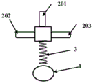
图2是本发明利用头部扭动感应的定位输入装置一种具体实施方式(有线)的结构示意图2 is a schematic structural diagram of a specific embodiment (wired) of a positioning input device utilizing head twist sensing according to the present invention
图3是图2所示定位输入装置的电路原理示意图;Fig. 3 is the circuit principle schematic diagram of the positioning input device shown in Fig. 2;
图4是本发明利用头部扭动感应的定位输入装置一种具体实施方式(无线)的电路原理示意图。FIG. 4 is a schematic diagram of the circuit principle of a specific embodiment (wireless) of a positioning input device utilizing head twist sensing according to the present invention.
具体实施方式Detailed ways
下面结合附图对本发明的具体实施方式进行描述,以便本领域的技术人员更好地理解本发明。需要特别提醒注意的是,在以下的描述中,当已知功能和设计的详细描述也许会淡化本发明的主要内容时,这些描述在这里将被忽略。The specific embodiments of the present invention are described below with reference to the accompanying drawings, so that those skilled in the art can better understand the present invention. It should be noted that, in the following description, when the detailed description of known functions and designs may dilute the main content of the present invention, these descriptions will be omitted here.
图2是本发明利用头部扭动感应的定位输入装置一种具体实施方式(有线)结构示意图。FIG. 2 is a schematic structural diagram of a specific embodiment (wired) of a positioning input device utilizing head twist sensing according to the present invention.
在本实施例中,如图2所示,本发明利用头部扭动感应的定位输入装置包括固定件1、3个压控元件组201~203组成的压控感应装置以及处理芯片3以及定位信号连接线4。In this embodiment, as shown in FIG. 2 , the positioning input device utilizing head twisting sensing according to the present invention includes a
在本实施例中,如图3压控元件组201~203采用压控电阻,其中一个压控元件组201(中间两个压控电阻组成)位于头部后方位置,用于当头部上下扭动时,该压控元件组产生压控信号,送入处理芯片,产生对应的压控感应信号;另外两个压控元件组202、203(分别由两侧的三个压控电阻组成)分别位于头部两侧,当头部左右扭动时,两个压控元件组202、203产生对应的压控感应信号,送入处理芯片,产生对应的压控感应信号。In this embodiment, as shown in FIG. 3, the voltage-controlled element groups 201-203 adopt voltage-controlled resistors. One of the voltage-controlled element groups 201 (composed of two voltage-controlled resistors in the middle) is located at the rear of the head, which is used when the head is twisted up and down. When moving, the voltage control element group generates a voltage control signal, which is sent to the processing chip to generate a corresponding voltage control induction signal; the other two voltage
在本实施例中,产生对应的压控感应信号以有线传输的方式即通过定位信号连接线4,发送给需要进行定位的设备。In this embodiment, the corresponding voltage-controlled inductive signal is generated and sent to the device that needs to be positioned by means of wired transmission, that is, through the positioning signal connection line 4 .
在具体实施过程中,压控电阻大小、芯片和工作方式可以根据实际情况进行调整。In the specific implementation process, the size of the voltage-controlled resistor, the chip and the working mode can be adjusted according to the actual situation.
图4是本发明利用头部扭动感应的定位输入装置一种具体实施方式(无线)的电路原理示意图。FIG. 4 is a schematic diagram of the circuit principle of a specific embodiment (wireless) of a positioning input device utilizing head twist sensing according to the present invention.
在本实施例中,如图4所示,本发明利用头部扭动感应的定位输入装置采用压控电容5作为压控感应装置,共4个,均匀分布于头部四周4个方向,当头部左右、上下扭动时,相应的压控电容改变,处理芯片3测量此电容改变即压控感应信号,并进行处理,得到对应的定位信号,并传输给通信芯片6,然后再以无线传输的方式(如蓝牙)发送给需要进行定位的设备。In this embodiment, as shown in FIG. 4 , the positioning input device utilizing head twisting induction of the present invention adopts voltage-controlled
本发明电路实现方式、压控电容电容、芯片以及工作方式可以根据实际情况进行调整。同时,本发明可以设计为穿戴式结构,所有构成部件置于一护颈内,不使用时也可作为保健和防护器具,随身携带,方便简单。The circuit implementation mode, the voltage-controlled capacitor capacitor, the chip and the working mode of the present invention can be adjusted according to the actual situation. At the same time, the present invention can be designed as a wearable structure, all the constituent parts are placed in a neck protector, and can also be used as a health care and protective device when not in use, which is convenient and simple to carry around.
在本实施例中,处理芯片3以及通信芯片6均置于头上(如帽子内)。电容大小、芯片数量和工作方式可以根据实际情况进行调整,但并不影响本发明的总体构架。In this embodiment, both the
在一种实施方式中,本发明中,当头部左右,或上下扭动角度超过一定阈值时,处理芯片才输出定位信号,且当头部左右,或上下扭动角度越大,产生的压控感应信号也越大,即压控电容的电容值改变大,或压控电阻的电阻值改变大等,处理芯片处理时,则产生更为快速移动的定位信号,如鼠标更为快速地移动。In one embodiment, in the present invention, the processing chip only outputs the positioning signal when the head twist angle exceeds a certain threshold, and when the head twist angle is larger, the pressure generated The larger the control induction signal is, that is, the larger the capacitance value of the voltage-controlled capacitor changes, or the larger the resistance value of the voltage-controlled resistor changes. .
在另一实施方式中,通过处理芯片处理后的定位信号,与头部扭动的幅度(角度)为线性关系,也与定位位置成线性关系。如果当头部左右,或上下扭动产生的压控感应信号精度较高时,比如左扭动10度,对应压控电阻从50欧姆变化为50.5欧姆。则处理芯片可以通过计算获得精确地定位,比如中心位置左移动10cm。如果每次10度的变化对应为压控电阻0.5欧姆的变化,则每次都可以精确地定位移动10cm,当然也可以通过提高压控感应装置的精度来提高整个系统装置的定位精度。所以本发明具有定位精度高的优点。In another embodiment, the positioning signal processed by the processing chip has a linear relationship with the amplitude (angle) of the head twist, and also has a linear relationship with the positioning position. If the precision of the voltage-controlled induction signal generated by twisting the head left and right, or up and down is high, such as twisting 10 degrees to the left, the corresponding voltage-controlled resistance changes from 50 ohms to 50.5 ohms. Then the processing chip can be accurately positioned by calculation, for example, the center position is moved 10cm to the left. If each change of 10 degrees corresponds to a change of 0.5 ohms in the voltage-controlled resistance, the positioning and movement of 10 cm can be accurately performed each time. Of course, the positioning accuracy of the entire system device can also be improved by improving the accuracy of the voltage-controlled sensing device. Therefore, the present invention has the advantage of high positioning accuracy.
尽管上面对本发明说明性的具体实施方式进行了描述,以便于本技术领域的技术人员理解本发明,但应该清楚,本发明不限于具体实施方式的范围,对本技术领域的普通技术人员来讲,只要各种变化在所附的权利要求限定和确定的本发明的精神和范围内,这些变化是显而易见的,一切利用本发明构思的发明创造均在保护之列。Although the illustrative specific embodiments of the present invention have been described above to facilitate the understanding of the present invention by those skilled in the art, it should be clear that the present invention is not limited to the scope of the specific embodiments. For those skilled in the art, As long as various changes are within the spirit and scope of the present invention as defined and determined by the appended claims, these changes are obvious, and all inventions and creations utilizing the inventive concept are included in the protection list.
Claims (4)
Priority Applications (1)
| Application Number | Priority Date | Filing Date | Title |
|---|---|---|---|
| CN201710316253.3A CN106909228B (en) | 2017-05-08 | 2017-05-08 | Positioning input device using head twisting induction |
Applications Claiming Priority (1)
| Application Number | Priority Date | Filing Date | Title |
|---|---|---|---|
| CN201710316253.3A CN106909228B (en) | 2017-05-08 | 2017-05-08 | Positioning input device using head twisting induction |
Publications (2)
| Publication Number | Publication Date |
|---|---|
| CN106909228A CN106909228A (en) | 2017-06-30 |
| CN106909228B true CN106909228B (en) | 2020-06-26 |
Family
ID=59210318
Family Applications (1)
| Application Number | Title | Priority Date | Filing Date |
|---|---|---|---|
| CN201710316253.3A Expired - Fee Related CN106909228B (en) | 2017-05-08 | 2017-05-08 | Positioning input device using head twisting induction |
Country Status (1)
| Country | Link |
|---|---|
| CN (1) | CN106909228B (en) |
Families Citing this family (1)
| Publication number | Priority date | Publication date | Assignee | Title |
|---|---|---|---|---|
| CN109941188B (en) * | 2019-04-26 | 2021-10-22 | 合肥京东方光电科技有限公司 | Vehicle turn signal control method, computer equipment and vehicle system |
Citations (6)
| Publication number | Priority date | Publication date | Assignee | Title |
|---|---|---|---|---|
| CN102478960A (en) * | 2010-11-29 | 2012-05-30 | 国际商业机器公司 | Man-machine interaction device, device and method for applying man-machine interaction device to virtual world |
| CN103064505A (en) * | 2011-10-18 | 2013-04-24 | 韦进文 | Simulation keyboard utilizing finger forms as keys |
| CN202975991U (en) * | 2012-11-16 | 2013-06-05 | 浙江工业大学 | Head-foot simultaneous control type mouse |
| CN103246349A (en) * | 2013-04-03 | 2013-08-14 | 汕头大学 | Input method of wearable finer-sensing wireless communication, and input device using input method |
| WO2015056376A1 (en) * | 2013-10-16 | 2015-04-23 | ソニー株式会社 | Input apparatus and electronic device provided therewith |
| CN105022471A (en) * | 2014-04-23 | 2015-11-04 | 王建勤 | Device and method for gesture recognition based on pressure sensor array |
Family Cites Families (6)
| Publication number | Priority date | Publication date | Assignee | Title |
|---|---|---|---|---|
| CN101566874A (en) * | 2008-04-24 | 2009-10-28 | 鸿富锦精密工业(深圳)有限公司 | Control device and electronic equipment using same |
| CN201945946U (en) * | 2011-01-20 | 2011-08-24 | 叶尔肯·拜山 | head-controlled mouse |
| CN104123002B (en) * | 2014-07-15 | 2017-03-01 | 河海大学常州校区 | Wireless body-sensing mouse based on head movement |
| US20170171595A1 (en) * | 2015-12-15 | 2017-06-15 | Le Holdings (Beijing) Co., Ltd. | Data transmission controlling device and data transmission controlling method for a mobile device |
| CN106235733A (en) * | 2016-09-13 | 2016-12-21 | 成都创慧科达科技有限公司 | A kind of control computer chair |
| CN206877279U (en) * | 2017-05-08 | 2018-01-12 | 电子科技大学 | A positioning input device utilizing head twisting induction |
-
2017
- 2017-05-08 CN CN201710316253.3A patent/CN106909228B/en not_active Expired - Fee Related
Patent Citations (6)
| Publication number | Priority date | Publication date | Assignee | Title |
|---|---|---|---|---|
| CN102478960A (en) * | 2010-11-29 | 2012-05-30 | 国际商业机器公司 | Man-machine interaction device, device and method for applying man-machine interaction device to virtual world |
| CN103064505A (en) * | 2011-10-18 | 2013-04-24 | 韦进文 | Simulation keyboard utilizing finger forms as keys |
| CN202975991U (en) * | 2012-11-16 | 2013-06-05 | 浙江工业大学 | Head-foot simultaneous control type mouse |
| CN103246349A (en) * | 2013-04-03 | 2013-08-14 | 汕头大学 | Input method of wearable finer-sensing wireless communication, and input device using input method |
| WO2015056376A1 (en) * | 2013-10-16 | 2015-04-23 | ソニー株式会社 | Input apparatus and electronic device provided therewith |
| CN105022471A (en) * | 2014-04-23 | 2015-11-04 | 王建勤 | Device and method for gesture recognition based on pressure sensor array |
Also Published As
| Publication number | Publication date |
|---|---|
| CN106909228A (en) | 2017-06-30 |
Similar Documents
| Publication | Publication Date | Title |
|---|---|---|
| CN103105945B (en) | A kind of man-machine interaction ring supporting multi-touch gesture | |
| CN204695282U (en) | The touch point recognition device of touch-screen | |
| CN104122988B (en) | Motion sensing device and motion sensing system thereof | |
| CN103699219B (en) | A kind of intelligent glasses interactive system and intelligent interactive method | |
| CN201562264U (en) | Self-adaptive intelligent interactive projector | |
| CN106909228B (en) | Positioning input device using head twisting induction | |
| CN102135823A (en) | Intelligent electronic handwriting pen | |
| CN206877279U (en) | A positioning input device utilizing head twisting induction | |
| CN103955297A (en) | Space operation type mouse | |
| CN107092360A (en) | A kind of positioning input device of utilization wrist twisting sensing | |
| CN206848945U (en) | A kind of positioning input device that sensing is twisted using wrist | |
| CN201936249U (en) | Light reflection type mobile sign language identification system | |
| CN103955315A (en) | Curved surface touch screen with flexible touch film and manufacture method thereof | |
| CN1240039A (en) | Pointing device for computer | |
| CN203606780U (en) | Multi-touch and gesture recognition fusion system | |
| CN103838401A (en) | Computer handwriting pen with pressure sensing function and free of writing pad | |
| TWI498793B (en) | Optical touch system and control method | |
| CN103777756A (en) | Glass screen-based man-machine interaction system | |
| CN103616955A (en) | Calligraphy or gesture recognition method and device | |
| CN204650450U (en) | A kind of non-hand-held mouse system | |
| CN103529960A (en) | Air mouse based on magnetic positioning technology and method | |
| CN205281417U (en) | A 3D mouse suitable for holographic imaging and its system | |
| CN104102391A (en) | Optical sensing positioning electronic whiteboard and positioning method thereof | |
| CN104951149B (en) | The touch point identification device of touch-screen | |
| CN208092656U (en) | Finger cot type wireless mouse |
Legal Events
| Date | Code | Title | Description |
|---|---|---|---|
| PB01 | Publication | ||
| PB01 | Publication | ||
| SE01 | Entry into force of request for substantive examination | ||
| SE01 | Entry into force of request for substantive examination | ||
| GR01 | Patent grant | ||
| GR01 | Patent grant | ||
| CF01 | Termination of patent right due to non-payment of annual fee | ||
| CF01 | Termination of patent right due to non-payment of annual fee |
Granted publication date: 20200626 |