CN1069105A - Sungle-cylinder, double-action type hydraulic slurry pump - Google Patents
Sungle-cylinder, double-action type hydraulic slurry pump Download PDFInfo
- Publication number
- CN1069105A CN1069105A CN 92108815 CN92108815A CN1069105A CN 1069105 A CN1069105 A CN 1069105A CN 92108815 CN92108815 CN 92108815 CN 92108815 A CN92108815 A CN 92108815A CN 1069105 A CN1069105 A CN 1069105A
- Authority
- CN
- China
- Prior art keywords
- oil
- cylinder
- piston
- slurry pump
- pump
- Prior art date
- Legal status (The legal status is an assumption and is not a legal conclusion. Google has not performed a legal analysis and makes no representation as to the accuracy of the status listed.)
- Granted
Links
- 239000002002 slurry Substances 0.000 title claims abstract description 25
- 230000009977 dual effect Effects 0.000 claims abstract description 13
- 230000003139 buffering effect Effects 0.000 claims description 11
- 230000017105 transposition Effects 0.000 claims description 8
- 229910052757 nitrogen Inorganic materials 0.000 claims description 3
- 230000002457 bidirectional effect Effects 0.000 claims description 2
- 238000000605 extraction Methods 0.000 claims description 2
- 229910052698 phosphorus Inorganic materials 0.000 claims description 2
- 238000006073 displacement reaction Methods 0.000 abstract description 8
- 230000005540 biological transmission Effects 0.000 abstract description 4
- 239000012530 fluid Substances 0.000 abstract description 3
- 239000003208 petroleum Substances 0.000 abstract description 3
- 230000009347 mechanical transmission Effects 0.000 abstract description 2
- 239000003921 oil Substances 0.000 description 71
- 230000033001 locomotion Effects 0.000 description 8
- 239000007788 liquid Substances 0.000 description 5
- 238000011161 development Methods 0.000 description 3
- 239000000446 fuel Substances 0.000 description 2
- XLYOFNOQVPJJNP-UHFFFAOYSA-N water Substances O XLYOFNOQVPJJNP-UHFFFAOYSA-N 0.000 description 2
- 238000013459 approach Methods 0.000 description 1
- 230000015572 biosynthetic process Effects 0.000 description 1
- 230000015556 catabolic process Effects 0.000 description 1
- 238000006243 chemical reaction Methods 0.000 description 1
- 239000010779 crude oil Substances 0.000 description 1
- 238000013461 design Methods 0.000 description 1
- 238000010586 diagram Methods 0.000 description 1
- 238000005553 drilling Methods 0.000 description 1
- 238000011010 flushing procedure Methods 0.000 description 1
- 239000010720 hydraulic oil Substances 0.000 description 1
- 230000013011 mating Effects 0.000 description 1
- 238000000034 method Methods 0.000 description 1
- 230000010349 pulsation Effects 0.000 description 1
- 238000005086 pumping Methods 0.000 description 1
- 238000011084 recovery Methods 0.000 description 1
- 239000004576 sand Substances 0.000 description 1
- 238000007789 sealing Methods 0.000 description 1
- 230000035945 sensitivity Effects 0.000 description 1
- 239000003381 stabilizer Substances 0.000 description 1
- 238000012360 testing method Methods 0.000 description 1
- 238000012546 transfer Methods 0.000 description 1
Images


Landscapes
- Reciprocating Pumps (AREA)
- Fluid-Pressure Circuits (AREA)
Abstract
The invention belongs to fluid machinery.Slurry pump is one of key equipment of petroleum industry, mostly adopt mechanically operated form at present both at home and abroad, three cylinder single-acting formulas commonly, though it has nonuniformity of displacement preferably than other mechanical transmission form, it also exists structure bulky complex, inefficient problem.The Sungle-cylinder, double-action type hydraulic slurry pump that this programme provides is that the oil cylinder by the single-cylinder dual-action double piston-rod of the Hydraulic Power Transmission System of band hydraulic control automatic reversing apparatus is driven, and is characterized in this pump displacement inequality degree near 0, and volume is little, and is in light weight, and working stability is reliable.
Description
The invention belongs to fluid machinery, it relates to the single-cylinder dual-action mud pump structure that hydraulic pressure automatic reverse drives.
In the engineering field, especially need under high pressure big proportion of transfer of highly viscous or high sand content on the petroleum industry and the little relatively liquid of flow, during as sticking well as circulating mud with inject cementing concrete; Be used as Crude Oil Transportation during oil recovery, well-flushing water filling and formation breakdown, so slurry pump is a kind of general key equipment on petroleum industry.Mostly be to adopt mechanically operated form at present both at home and abroad on slurry pump, in the reciprocating acquisition of pump, the single-cylinder single-acting pump that drives with crank block type does not have Practical significance, because its nonuniformity of displacement is very big, its numerical value is 3.14; Also have three cylinder single-acting formula pumps in addition, its crank phase differs 120 °, and four cylinder single-actings advance to be similar to duplex double action pump, and their structure and discharge curve are seen Fig. 1-5.To be able to reasons of development be because of its nonuniformity of displacement is 0.141 to triplex single action pump since the sixties, more much lower than the nonuniformity of displacement 0.314 of duplex double action pump, and drilling efficiency is significantly improved.In recent years the oil hydraulic pump that just occurs is steady because of hydraulic motion, and has adopted special flow equilibrium device, so the flow of pump output is also more stable, must be that stable more and high efficiency direction develops towards flow by the requirement of development form.Obtain following several pieces of close data through Patent Office of the People's Republic of China retrieval: 1. EP0380777 " positive-displacement pump of delivery of brewed liquid " patent.Its positive-displacement pump is driven by the two-way cylinder of a single-piston rod, and its commutation is to be realized by two limit switches of the rigid joint dish on piston rod collision control dispenser, and this limit switch can be electric, hydraulic pressure or other form; 2. US3142258 " pump structure " patent: it is a plastic part pump structure of pumping liquid or semi-fluid liquid, its driven medium is a pressurized air, the position of two series connection cylinder body inner carrier motions is limited by the adjustable limiting stopper on two ends cylinder top, and the collision block on the also available piston rod one end sponson of its commutation problem and the mating reaction of sensitive switch realize; 3. US3700360 " double-acting tandem piston pump " patent, it is the double-acting pump that the pressure oil driving oil cylinder is connected in series, piston is connected that forms with the engine-driven oil hydraulic pump on the vehicle, this pump is used for transporting water or liquid, feature in its transmission is: the commutation of driven plunger in driving oil cylinder motion is the sensitive switch by an extension rod control circuit in the piston rod in two cylinders, realizes with the pilot valve of electromagnetic action is reversing valve operated.Three contrast patent descriptions that above-mentioned retrieval obtains do not use the form of hydraulically powered single-cylinder dual-action in the field of slurry pump, and their common features are: though they all are the pumps of the double action of hydraulic control, its commutation problem all is to adopt the sensitive switch of mechanical motion collision circuit to realize.
The slurry pump that the purpose of this invention is to provide a kind of single-cylinder dual-action of tandem piston, the operation of its commutation are to adopt the hydraulic transmission mode that has hydraulic pressure automatic control reversing arrangement to realize.
By as above design, the single-cylinder dual-action hydraulic slurry pump that this programme provided, it includes the changement of the automatic reciprocating driving oil cylinder of hydraulic pressure, and the double action pump, its concrete feature is: the slurry pump of this single-cylinder dual-action formula is that the hydraulic jack of coaxial single-cylinder dual-action double piston-rod drives.
Hydraulic driving oil cylinder is controlled by hydraulic pressure automatic control changement in this programme, this mechanism comprises a two-position four way change valve and a two-position four-way pilot reversing valve that has two side controller small oil tanks, its driving oil cylinder can have two kinds of forms, a kind of is the oil cylinder of not being with the double piston-rod piston form of damper piston, and another kind is the oil cylinder that has damper piston and the double piston-rod piston form of buffering oil pocket with matching is arranged on end cap.The oil circuit of driving oil cylinder changement is arranged: the pressure oil of free pump output, the work that reaches are returned two pipelines of oil sump afterwards and are received E, the F of commutation pilot valve and A, the B of selector valve simultaneously, the two oil pipe C, two ends M, N or U, the V that D is connected to oil cylinder that pick out from selector valve, also receive inner K, the L of controller small oil tank simultaneously, two oil pipe G, the H that picks out from pilot reversing valve is connected to two working oil chamber I, the J of selector valve, oil pipe O, the P of two commutation signal that pick out from oil cylinder or outer end Q, the R that S, T receive two controller small oil tanks.It does not have the oil cylinder of commutation signal oil duct and has the end cap that passes in and out oil duct by the double piston-rod piston, near the place, two ends with the oil cylinder of damper piston and is formed.The oil cylinder that has damper piston is the oil cylinder that is had the commutation signal oil duct by the double piston-rod piston that has the bidirectional buffering piston, two ends proximal cover place, the cylinder cap that has the buffering oil pocket that matches with damper piston is formed, in the buffering oil pocket of cylinder cap into oil expulsion channel is arranged, on the end face of cylinder cap, also have the oil extraction oil duct.The controller small oil tank at two-position four-way pilot reversing valve two ends is by small oil tank, equalizing piston and the push rod of commutation pilot valve transposition is constituted in this programme.
Slurry pump is the single-cylinder dual-action form in this programme, changes many, the inefficient looks of traditional mechanical driving structure bulky complex, fault, and its compact structure, volume are little, in light weight, can reliablely and stablely work for a long time.The hydraulic jack that drives it also is a double action, but it adopts the difference of double piston-rod form with piston two sides lifting surface area in the balance slurry pump, thereby obtains the discharge curve of stabilizer pole.Again because hydraulic transmission can obtain straight line motion and changement response capability with sensitivity at the uniform velocity, it can obtain nonuniformity of displacement and be almost 0 perfect condition.It is shorter than Transmitted chains with the mechanical transmission form, and friction pair is few, so the efficient height be more than 0.7 through test total efficiency when delivery pressure is 1.7Mpa, so its starting power is little, only be below the 1KW, and former pump is more than the 6KW.
Adopt this programme can embody following superiority: 1. it can obtain utmost point flow stably, and its uneven degree almost is bordering on 0; 2. it has higher total efficiency; 3. its volume is little, and in light weight only is the 2/5-1/3 of former pump weight; 4. because flow is steady, can save the equalizing reservoir that overcomes flow pulsation; 5. absence of collision part in working, no heater element, so fault is few, and the life-span height.Through the hydraulically powered slurry pump of expert judgments will be the direction of development.
Fig. 1 is the schematic representation of the single-cylinder single-acting pump of crank block type driving.
Fig. 2 is the schematic representation of three cylinder single-acting formula pumps.
Fig. 3 is the schematic representation of duplex double action pump.
Fig. 4 is the discharge curve figure of triplex single action pump.
Fig. 5 is the discharge curve figure of duplex double action pump.
Fig. 6 is this programme single-cylinder dual-action discharge curve figure.
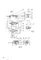
Fig. 7 is the schematic diagram of this programme single-cylinder dual-action formula slurry pump.
Fig. 8 is the structural representation of controller small oil tank.
Fig. 9 is the cylinder structure schematic representation of band damper piston.
Working principle and working procedure below in conjunction with description of drawings this programme embodiment, slurry pump among the figure (17) is a double-acting pump, its driving oil cylinder can have two kinds of forms, a kind of is not to be with damper piston, it is by oil cylinder (6), double piston-rod piston (7) and end cap (8) constitute, on its end cap inlet and outlet of fuel channel is arranged, on the distance of the two ends of oil cylinder, be provided with the oil circuit of commutation signal greater than piston thickness, the driving oil cylinder of band damper piston is the oil cylinder (12) that is had the commutation signal oil circuit by the double piston-rod piston (13) that two ends have a damper piston near the two end cap place, having the two end cap (14) that cushions the buffering oil pocket (16) that matches with damper piston constitutes, buffering oil pocket interior edge face is provided with inlet and outlet of fuel channel, on the end face of end cap, also be provided with the oil-feed oil circuit of band one-way valve (15), the hydraulic oil that drives leaves in the oil sump (1), be input to selector valve (3) through oil pump (2), commutated the again control of pilot valve (4) of selector valve, the two ends of pilot valve have controller small oil tank (5), and its controller small oil tank is by small oil tank (9), equalizing piston (10) and the push rod (11) that pilot valve is replaced.
The pressure oil of oil pump output has been determined the position of selector valve through E, G to I during work, and pressure oil also promotes the piston right lateral through A, C to M, enters the controller small oil tank through C, K simultaneously, it and the wet goods pressure that enters small oil tank from O, Q, so equalizing piston is stablized motionless.The oil of piston right-hand member approaches zero-pressure and leaks into oil sump through N, D, B at this moment, and L and R also are isobaric, and its equalizing piston is stablized motionless.When the piston right lateral surpasses the P point near right end cap to its rear rim, P point and M, O equipressure, so the pressure at R place is higher than L, equalizing piston is to left movement, make the pilot valve transposition by push rod, pressure oil is delivered to J through E, H, makes the selector valve transposition, pressure oil through A, D to N, make the piston reverses direction motion, present P, N equipressure, M, O equipressure this moment again, make pilot valve and selector valve be in steady state, enter the next one-work cycle.Do not take from the rear of piston with the transposition signal of cushion cylinder, and the place ahead that its transposition signal of the oil cylinder of band damper piston is taken from piston.S, V, W are in isopiestic state when piston moves right, this moment, T, V were in nearly zero-pressure, the boss of damper piston begins to contact with the buffering oil pocket when piston walks to right-hand member, because the X pipeline is provided with one-way valve, oil circuit is obstructed, and the interior oil pressure fast rise of end cap recess this moment causes R, L imbalance, make the pilot valve transposition, and then make the selector valve transposition.
Through adjusting the flow of pressure oil, can obtain the movement velocity of different pistons in the use, to adapt to the unequally loaded needs, the changement structure of this programme is small and exquisite, the oil circuit sealing, and working stability life-span height can be worked under open-air abominable ore deposit environment for a long time.
The slurry pump cylinder diameter ∮ 63 of this programme, frequency of okperation 82 times/minute, 300 liters/minute of mud output flows, delivery pressure are 20Mpa, this moment, the drive motor of oil pump was 15KW.
Claims (6)
1, a kind of single-cylinder dual-action hydraulic slurry pump, it includes the changement of hydraulic pressure automatic reciprocal cylinder, it is characterized in that this slurry pump (17) for single-cylinder dual-action formula structure, it is that hydraulic jack (6) or (22) by coaxial single-cylinder dual-action double piston-rod are driven.
2, according to the described slurry pump of claim 1, it is characterized in that the hydraulic jack that drives slurry pump is controlled by hydraulic pressure automatic control changement, this mechanism comprises a two-position four way change valve (3) and the two-position four-way pilot reversing valve (4) with two side controller small oil tanks (5).
3, according to the described slurry pump of claim 1, it is characterized in that the hydraulic jack that drives slurry pump can have two kinds of forms: a kind of is the oil cylinder of not being with the double piston-rod piston form of damper piston; Another kind is band damper piston and the oil cylinder that the double piston-rod piston form of buffering oil pocket with matching is arranged on end cap.
4, according to the described slurry pump of claim 1-3, the oil circuit that it is characterized in that its driving oil cylinder changement is arranged and to be: from the pressure oil of oil pump (2) output, and two pipelines that turn back to oil sump (1) after the work are received the EF of commutation pilot valve (4) simultaneously, and the A of selector valve (3), B, the two oil pipe C that pick out from selector valve, D is connected to the two ends M of oil cylinder, N or U, V, also receive the inner K of controller small oil tank (5) simultaneously, L, pick out two next oil pipe G from pilot valve, H is connected to two working oil chamber I of selector valve, J, the oil pipe O of two commutation signal that pick out from oil cylinder, P or S, T receives the outer end Q of two controller small oil tanks (5), R.
5,, it is characterized in that not having the oil cylinder (6) of commutation signal oil duct and have the end cap (8) that passes in and out oil duct near the place, two ends by double piston-rod piston (7) and being formed of it with the oil cylinder of damper piston according to the described slurry pump of claim 3; The oil cylinder that has damper piston is by the double piston-rod piston (13) that has the bidirectional buffering piston, proximal cover place, two ends has the oil cylinder (12) of commutation signal oil duct, the cylinder cap that has a buffering oil pocket (16) that matches with damper piston is formed, in the buffering oil pocket of cylinder cap into oil expulsion channel is arranged, on end face, also have the oil extraction oil duct.
6, according to the described slurry pump of claim 2, the controller small oil tank (5) that it is characterized in that its two-position four-way commutation pilot valve two ends is by small oil tank (9), equalizing piston (10) and the push rod (11) of commutation pilot valve transposition is constituted.
Priority Applications (1)
| Application Number | Priority Date | Filing Date | Title |
|---|---|---|---|
| CN 92108815 CN1026147C (en) | 1992-07-31 | 1992-07-31 | Single-cylinder double-acting hydraulic mud pump |
Applications Claiming Priority (1)
| Application Number | Priority Date | Filing Date | Title |
|---|---|---|---|
| CN 92108815 CN1026147C (en) | 1992-07-31 | 1992-07-31 | Single-cylinder double-acting hydraulic mud pump |
Publications (2)
| Publication Number | Publication Date |
|---|---|
| CN1069105A true CN1069105A (en) | 1993-02-17 |
| CN1026147C CN1026147C (en) | 1994-10-05 |
Family
ID=4943840
Family Applications (1)
| Application Number | Title | Priority Date | Filing Date |
|---|---|---|---|
| CN 92108815 Expired - Fee Related CN1026147C (en) | 1992-07-31 | 1992-07-31 | Single-cylinder double-acting hydraulic mud pump |
Country Status (1)
| Country | Link |
|---|---|
| CN (1) | CN1026147C (en) |
Cited By (5)
| Publication number | Priority date | Publication date | Assignee | Title |
|---|---|---|---|---|
| CN105952607A (en) * | 2016-05-19 | 2016-09-21 | 四川理工学院 | Hydraulically-powered high-flow metering pump |
| CN106523335A (en) * | 2016-08-25 | 2017-03-22 | 湖南莫尔顿智能勘探机器人有限公司 | Automatic reversing water pump |
| CN104533350B (en) * | 2014-12-18 | 2017-06-13 | 中国石油天然气股份有限公司 | Oil well fluid flooding pumping system |
| CN106870317A (en) * | 2017-04-18 | 2017-06-20 | 黄山市汇润机械有限公司 | A kind of hydraulic cylinder driven slush pump |
| CN121066891A (en) * | 2025-09-19 | 2025-12-05 | 开原市凯峰机械有限公司 | Hydraulic oil supplementing and distributing device |
Families Citing this family (2)
| Publication number | Priority date | Publication date | Assignee | Title |
|---|---|---|---|---|
| CN100455794C (en) * | 2006-05-31 | 2009-01-28 | 武汉方圆钛白粉有限责任公司 | Extrusion pump for thick slurry material conveying |
| WO2010066069A1 (en) * | 2008-12-12 | 2010-06-17 | Yu Chun Kwan | A fluid power device |
-
1992
- 1992-07-31 CN CN 92108815 patent/CN1026147C/en not_active Expired - Fee Related
Cited By (5)
| Publication number | Priority date | Publication date | Assignee | Title |
|---|---|---|---|---|
| CN104533350B (en) * | 2014-12-18 | 2017-06-13 | 中国石油天然气股份有限公司 | Oil well fluid flooding pumping system |
| CN105952607A (en) * | 2016-05-19 | 2016-09-21 | 四川理工学院 | Hydraulically-powered high-flow metering pump |
| CN106523335A (en) * | 2016-08-25 | 2017-03-22 | 湖南莫尔顿智能勘探机器人有限公司 | Automatic reversing water pump |
| CN106870317A (en) * | 2017-04-18 | 2017-06-20 | 黄山市汇润机械有限公司 | A kind of hydraulic cylinder driven slush pump |
| CN121066891A (en) * | 2025-09-19 | 2025-12-05 | 开原市凯峰机械有限公司 | Hydraulic oil supplementing and distributing device |
Also Published As
| Publication number | Publication date |
|---|---|
| CN1026147C (en) | 1994-10-05 |
Similar Documents
| Publication | Publication Date | Title |
|---|---|---|
| CN209654022U (en) | A kind of hydraulic pressure drive injection device | |
| CA2940124C (en) | Hydraulically driven bellows pump | |
| US10612531B2 (en) | Hydraulically-driven double-acting mud pump | |
| GB2346938A (en) | Mains fuel gas reciprocating compressor | |
| US4790728A (en) | Dual-rigid-hollow-stem actuators in opposite-phase slurry pump drive having variable pumping speed and force | |
| US4606709A (en) | Liquid pump with sequential operating fluid pistons | |
| CN102094780A (en) | Hydraulic slurry pump | |
| CN1026147C (en) | Single-cylinder double-acting hydraulic mud pump | |
| CN2151272Y (en) | Single cylinder hydraulic mud pump | |
| CN2194423Y (en) | Energy-saving hydraulic pumping unit | |
| CN218000005U (en) | Multistage flow plunger pump hydraulic control system | |
| WO1984001002A1 (en) | Hydraulically actuated bore and well pump | |
| CN202040039U (en) | Single-acting hydraulic driving reciprocating plunger pump | |
| CN120332259A (en) | Plunger pump system, control method and filter press | |
| CN2073048U (en) | Automatic reciprocatable liquid-controlled cylinder system | |
| CN108644084B (en) | A kind of slush pump of hydraulic-driven | |
| CN212615198U (en) | Advection metering pump | |
| CN108679015B (en) | Hydraulically driven slurry pump | |
| CN206681924U (en) | A kind of hydraulic cylinder driven slush pump | |
| CN222686815U (en) | High-pressure grouting system | |
| JPH0381579A (en) | Hydraulic cylinder interlocking method in pump for forced feed of ready-mixed concrete and device thereof | |
| CN2256473Y (en) | Hydraulic driven metering pump | |
| RU2023909C1 (en) | Pump with muscular drive | |
| CN108730147A (en) | Hydraulic slurry pump | |
| CN2299167Y (en) | Reversing controlling device of concrete conveying pump |
Legal Events
| Date | Code | Title | Description |
|---|---|---|---|
| C10 | Entry into substantive examination | ||
| SE01 | Entry into force of request for substantive examination | ||
| C06 | Publication | ||
| PB01 | Publication | ||
| C14 | Grant of patent or utility model | ||
| GR01 | Patent grant | ||
| C19 | Lapse of patent right due to non-payment of the annual fee | ||
| CF01 | Termination of patent right due to non-payment of annual fee |