CN106919033B - Image forming apparatus with a toner supply device - Google Patents
Image forming apparatus with a toner supply device Download PDFInfo
- Publication number
- CN106919033B CN106919033B CN201611230904.9A CN201611230904A CN106919033B CN 106919033 B CN106919033 B CN 106919033B CN 201611230904 A CN201611230904 A CN 201611230904A CN 106919033 B CN106919033 B CN 106919033B
- Authority
- CN
- China
- Prior art keywords
- image
- sheet
- image forming
- transparent member
- forming apparatus
- Prior art date
- Legal status (The legal status is an assumption and is not a legal conclusion. Google has not performed a legal analysis and makes no representation as to the accuracy of the status listed.)
- Expired - Fee Related
Links
Images


Classifications
-
- G—PHYSICS
- G03—PHOTOGRAPHY; CINEMATOGRAPHY; ANALOGOUS TECHNIQUES USING WAVES OTHER THAN OPTICAL WAVES; ELECTROGRAPHY; HOLOGRAPHY
- G03G—ELECTROGRAPHY; ELECTROPHOTOGRAPHY; MAGNETOGRAPHY
- G03G21/00—Arrangements not provided for by groups G03G13/00 - G03G19/00, e.g. cleaning, elimination of residual charge
- G03G21/20—Humidity or temperature control also ozone evacuation; Internal apparatus environment control
- G03G21/203—Humidity
-
- G—PHYSICS
- G03—PHOTOGRAPHY; CINEMATOGRAPHY; ANALOGOUS TECHNIQUES USING WAVES OTHER THAN OPTICAL WAVES; ELECTROGRAPHY; HOLOGRAPHY
- G03G—ELECTROGRAPHY; ELECTROPHOTOGRAPHY; MAGNETOGRAPHY
- G03G21/00—Arrangements not provided for by groups G03G13/00 - G03G19/00, e.g. cleaning, elimination of residual charge
- G03G21/20—Humidity or temperature control also ozone evacuation; Internal apparatus environment control
-
- G—PHYSICS
- G03—PHOTOGRAPHY; CINEMATOGRAPHY; ANALOGOUS TECHNIQUES USING WAVES OTHER THAN OPTICAL WAVES; ELECTROGRAPHY; HOLOGRAPHY
- G03G—ELECTROGRAPHY; ELECTROPHOTOGRAPHY; MAGNETOGRAPHY
- G03G21/00—Arrangements not provided for by groups G03G13/00 - G03G19/00, e.g. cleaning, elimination of residual charge
- G03G21/20—Humidity or temperature control also ozone evacuation; Internal apparatus environment control
- G03G21/206—Conducting air through the machine, e.g. for cooling, filtering, removing gases like ozone
-
- H—ELECTRICITY
- H04—ELECTRIC COMMUNICATION TECHNIQUE
- H04N—PICTORIAL COMMUNICATION, e.g. TELEVISION
- H04N1/00—Scanning, transmission or reproduction of documents or the like, e.g. facsimile transmission; Details thereof
- H04N1/00976—Arrangements for regulating environment, e.g. removing static electricity
- H04N1/00992—Humidity control, e.g. removing condensation
-
- G—PHYSICS
- G03—PHOTOGRAPHY; CINEMATOGRAPHY; ANALOGOUS TECHNIQUES USING WAVES OTHER THAN OPTICAL WAVES; ELECTROGRAPHY; HOLOGRAPHY
- G03G—ELECTROGRAPHY; ELECTROPHOTOGRAPHY; MAGNETOGRAPHY
- G03G2221/00—Processes not provided for by group G03G2215/00, e.g. cleaning or residual charge elimination
- G03G2221/16—Mechanical means for facilitating the maintenance of the apparatus, e.g. modular arrangements and complete machine concepts
- G03G2221/1645—Mechanical means for facilitating the maintenance of the apparatus, e.g. modular arrangements and complete machine concepts for conducting air through the machine, e.g. cooling
Landscapes
- Engineering & Computer Science (AREA)
- Environmental & Geological Engineering (AREA)
- Environmental Sciences (AREA)
- Biodiversity & Conservation Biology (AREA)
- Ecology (AREA)
- Atmospheric Sciences (AREA)
- Life Sciences & Earth Sciences (AREA)
- Physics & Mathematics (AREA)
- General Physics & Mathematics (AREA)
- Multimedia (AREA)
- Signal Processing (AREA)
- Electrophotography Configuration And Component (AREA)
- Control Or Security For Electrophotography (AREA)
- Exposure Or Original Feeding In Electrophotography (AREA)
Abstract
本公开涉及图像形成装置。该图像形成装置100包括:感光鼓21,通过用从光源29通过透明部件26发射的光束进行扫描在该感光鼓上形成静电潜像;显影辊23,显影在感光鼓21上形成的静电潜像以在感光鼓21上形成图像;转印辊24,将通过显影辊23显影和形成的图像转印到片材S;定影部分30,将通过转印辊24转印在片材S上的图像热定影到片材S;以及凝结部件28,设置在从定影部分30到透明部件36的气流路径A中,并且凝结和收集气流中的水蒸汽。
The present disclosure relates to image forming apparatuses. The image forming apparatus 100 includes: a photosensitive drum 21 on which an electrostatic latent image is formed by scanning with a light beam emitted from a light source 29 through a transparent member 26; and a developing roller 23 which develops the electrostatic latent image formed on the photosensitive drum 21 to form an image on the photosensitive drum 21; the transfer roller 24, which transfers the image developed and formed by the developing roller 23 to the sheet S; the fixing part 30, which transfers the image on the sheet S by the transfer roller 24 heat-fixing to the sheet S; and a condensation member 28, which is provided in the air flow path A from the fixing portion 30 to the transparent member 36, and condenses and collects water vapor in the air flow.
Description
技术领域technical field
本发明涉及应用电子照相系统的图像形成装置,诸如复印机、打印机、传真机或加入上述这些设备的多功能外设。The present invention relates to an image forming apparatus to which an electrophotographic system is applied, such as a copier, a printer, a facsimile machine, or a multifunctional peripheral incorporating these devices.
背景技术Background technique
常规上,应用电子照相系统的诸如复印机、打印机、传真机或加入上述这些设备的多功能外设之类的图像形成装置通过用来自光源的与图像数据对应的光束照射感光体并且扫描和曝光感光体,在感光体上形成静电潜像。并且,图像形成装置通过显影单元向静电潜像供给显影剂以使得静电潜像可视化为图像,并且将图像从感光体转印到作为记录介质的片材,以由此在片材上形成图像。Conventionally, an image forming apparatus such as a copier, a printer, a facsimile machine, or a multifunctional peripheral incorporating the above-mentioned devices to which an electrophotographic system is applied irradiates a photoreceptor with a light beam corresponding to image data from a light source and scans and exposes the photoreceptor. body, forming an electrostatic latent image on the photoreceptor. And, the image forming apparatus supplies a developer to the electrostatic latent image through a developing unit to visualize the electrostatic latent image as an image, and transfers the image from the photoreceptor to a sheet as a recording medium to thereby form an image on the sheet.
当在图像形成装置被放置在低温处之后装置主体周围的温度由于空调设施等急剧升高时,该装置中的大气温度从低温急剧升高到高温。当导致该装置中的大气温度急剧升高时,该装置中的部件的温度不能容易地在短时间内追随周围环境的温度变化。因此,会在部件的表面上导致凝结。When the temperature around the apparatus main body rises sharply due to air-conditioning facilities or the like after the image forming apparatus is placed at a low temperature, the atmospheric temperature in the apparatus rises sharply from a low temperature to a high temperature. When the atmospheric temperature in the device is caused to rise sharply, the temperature of the components in the device cannot easily follow the temperature change of the surrounding environment in a short time. As a result, condensation can be induced on the surface of the part.
并且,在大量通过已吸收湿气的片材的情况下,该装置中的温度急剧上升并且会在装置中的部件的表面上导致凝结。在这种情况下,在发射来自激光光源的光束的光学传感器中的光学部件等上导致的凝结导致扫描和曝光感光体的光束的光学特性的劣化。Also, with the passage of a large number of sheets that have absorbed moisture, the temperature in the device rises sharply and can cause condensation on the surfaces of the components in the device. In this case, condensation caused on optical components and the like in the optical sensor that emits the light beam from the laser light source causes deterioration of the optical characteristics of the light beam scanning and exposing the photoreceptor.
相反,日本专利公开No.1993-182227涉及抑制光学扫描器中的光学部件上的凝结的图像形成装置,并且公开了在箱状光学单元中容纳包含半导体激光器或反射镜的光学部件并且密封该光学单元的内部的配置。因此,在日本专利公开No.1993-182227的图像形成装置中,可防止升高温度下的大气与露点温度或更低温度下的光学部件接触,并且可防止包含半导体激光器等的光学部件上的凝结。In contrast, Japanese Patent Laid-Open No. 1993-182227 relates to an image forming apparatus that suppresses condensation on an optical member in an optical scanner, and discloses accommodating an optical member including a semiconductor laser or a mirror in a box-shaped optical unit and sealing the optical member The internal configuration of the unit. Therefore, in the image forming apparatus of Japanese Patent Laid-Open No. 1993-182227, the atmosphere at an elevated temperature can be prevented from coming into contact with the optical member at the dew point temperature or lower, and the optical member including the semiconductor laser and the like can be prevented from being in contact with the optical member. coagulate.
但是,日本专利公开No.1993-182227具有以下问题,即,由于光学单元的外表面温度容易变为露点温度或更低,因此,在光学单元的光通过表面的外表面上导致凝结,并且光束的光学特性劣化,从而导致对于感光体的需要的光量的减少。However, Japanese Patent Laid-Open No. 1993-182227 has the problem that since the outer surface temperature of the optical unit easily becomes the dew point temperature or lower, condensation is caused on the outer surface of the light passing surface of the optical unit, and the light beam The optical properties of the photoreceptor are deteriorated, resulting in a reduction in the amount of light required for the photoreceptor.
并且,日本专利公开No.2005-338576涉及图像形成装置,并且公开了在光束扫描单元与图像形成单元之间设置加热器单元并且加热光束扫描单元与图像形成单元之间的大气的配置。并且,日本专利公开No.2005-338576公开了如下配置,该配置导致被加热的大气从相对于装置主体的安装表面沿上下方向排列的多个出射窗口的最下面的部分流向其最上面的部分,以用被加热的大气使多个出射窗口升温以由此抑制多个出射窗口上凝结的出现。Also, Japanese Patent Laid-Open No. 2005-338576 relates to an image forming apparatus, and discloses a configuration in which a heater unit is provided between the beam scanning unit and the image forming unit and the atmosphere between the beam scanning unit and the image forming unit is heated. Also, Japanese Patent Laid-Open No. 2005-338576 discloses a configuration that causes heated air to flow from the lowermost portion to the uppermost portion of a plurality of exit windows arranged in the up-down direction with respect to the mounting surface of the apparatus main body , to warm the exit windows with the heated atmosphere to thereby suppress the occurrence of condensation on the exit windows.
但是,在日本专利公开No.2005-338576中,新添加加热器单元招致制造成本增加。并且,为了防止极冷区域中的凝结,加热器需要恒定地为ON(开启),由此在成本和节能的方面存在问题。However, in Japanese Patent Laid-Open No. 2005-338576, newly adding a heater unit incurs an increase in manufacturing cost. Also, in order to prevent condensation in an extremely cold region, the heater needs to be constantly ON, thereby causing problems in terms of cost and energy saving.
发明内容SUMMARY OF THE INVENTION
根据本发明的图像形成装置包括:图像承载部件,通过用从光源通过透明部件发射的光束进行扫描,在所述图像承载部件上形成静电潜像;显影部分,用显影剂显影在图像承载部件上形成的静电潜像以在图像承载部件上形成图像;转印部分,将由显影部分显影和形成的图像转印到记录介质;定影部分,将通过转印部分转印到记录介质的图像热定影到记录介质;以及凝结部件,被设置在从定影部分到透明部件的气流路径中,并且凝结和收集气流中的水蒸汽。An image forming apparatus according to the present invention includes: an image bearing member on which an electrostatic latent image is formed by scanning with a light beam emitted from a light source through a transparent member; and a developing portion on which the image bearing member is developed with a developer The electrostatic latent image is formed to form an image on the image bearing member; the transfer part, the image developed and formed by the developing part is transferred to the recording medium; the fixing part, the image transferred to the recording medium by the transfer part is thermally fixed to the recording medium; a recording medium; and a condensing member disposed in an air flow path from the fixing portion to the transparent member, and condensing and collecting water vapor in the air flow.
根据以下参照附图对示例性实施例的说明,本发明的其它特征将变得清楚。Other features of the present invention will become apparent from the following description of exemplary embodiments with reference to the accompanying drawings.
附图说明Description of drawings
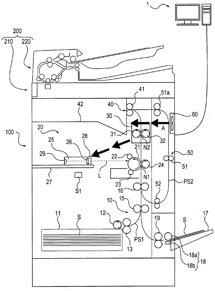
图1是根据本发明的实施例的图像形成装置的截面图;1 is a cross-sectional view of an image forming apparatus according to an embodiment of the present invention;
图2是根据本发明的实施例的激光扫描器及其周边的透视图;2 is a perspective view of a laser scanner and its surroundings according to an embodiment of the present invention;
图3是根据本发明的实施例的图像形成装置的主要部分的放大透视图;3 is an enlarged perspective view of a main part of the image forming apparatus according to the embodiment of the present invention;
图4是示出根据本发明的实施例的图像形成装置的控制器的配置的框图;4 is a block diagram showing a configuration of a controller of an image forming apparatus according to an embodiment of the present invention;
图5是示出根据本发明的实施例的图像形成控制器的配置的框图;5 is a block diagram showing a configuration of an image forming controller according to an embodiment of the present invention;
图6是示出根据本发明的实施例的改变最短距离d3时的最短距离d3与反射浓度之间的关系的示图;以及6 is a diagram illustrating a relationship between the shortest distance d3 and the reflection density when the shortest distance d3 is changed according to an embodiment of the present invention; and
图7是示出根据本发明的实施例的图像形成装置的操作的流程图。FIG. 7 is a flowchart showing the operation of the image forming apparatus according to the embodiment of the present invention.
具体实施方式Detailed ways
以下,将参照附图详细描述本发明的实施例。Hereinafter, embodiments of the present invention will be described in detail with reference to the accompanying drawings.
<图像形成装置的配置><Configuration of Image Forming Apparatus>
将参照图1详细描述根据本发明的实施例的图像形成装置100的配置。该图像形成装置100被设置有读取原稿的图像的图像读取装置200。该图像读取装置200包含读取原稿的图像的图像读取部分210和将原稿馈送到图像读取部分210的原稿馈送部分220。The configuration of the
该图像形成装置100包含片材馈送部分10、图像形成部分20、定影部分30、片材排出部分40、片材再馈送部分50、风扇60和环境传感器S1。This
片材馈送部分10将作为记录介质加载在片材盒11或多片材托盘17中的片材S供给到图像形成部分20。具体而言,片材馈送部分10包含片材盒11、拾取辊12、分离辊13、馈送辊15、对齐辊16、多片材托盘17、供给辊18和供给辊19。The
在片材盒11中,加载和容纳片材S。In the
拾取辊12旋转以将容纳在片材盒11中的片材S供给到分离辊13。The
分离辊13包含正向旋转辊和反向旋转辊。在片材S被双重馈送的情况下,分离辊13将双重馈送的片材S分离为一个片材,并且将片材S供给到馈送路径PS1。The
馈送辊15将从馈送路径PS1供给的片材S供给到对齐辊16。The
对齐辊16在预定的定时处旋转。对齐辊16在停止旋转时通过导致从馈送辊15或馈送辊52供给的片材S的尖端追随压合部来校正片材S的倾斜馈送。在对齐辊16旋转时,对齐辊16将倾斜馈送被校正的片材S供给到感光鼓21。The
在多片材托盘17中,加载片材S。In the
供给辊18包含辊18a和分离板18b,并且将加载在多片材托盘17中的片材S分离为一个片材并且将片材S供给到供给辊19。The
供给辊19将从供给辊18供给的片材S供给到馈送辊15。The
图像形成部分20在感光鼓21上形成静电潜像并且通过显影剂在感光鼓21上显影静电潜像。具体而言,图像形成部分20包含感光鼓21、带电辊22、显影辊23、转印辊24、激光单元外壳25、透明部件26、扫描器台架27、凝结部件28和光源29。The
作为图像承载部件的感光鼓21的表面由带电辊22均匀带电。用来自光源29的作为光束的激光L照射感光鼓21,使得用激光L照射的部分上的电荷被去除,并且形成静电潜像。The surface of the
从带电偏置电源(未示出)向带电辊22施加带电偏置电压,并且使感光鼓21带电。A charging bias voltage is applied to the
作为显影部分的显影辊23导致显影剂附着到感光鼓21,由此显影在感光鼓21上形成的静电潜像并且在感光鼓21上形成图像(显影剂图像)。The developing
作为转印部分的转印辊24与感光鼓21形成转印压合部N1,并且向从对齐辊16供给到转印压合部N1的片材S施加偏置电压,并且将在感光鼓21上形成的显影剂图像转印到片材S。转印辊24在转印压合部N1中与感光鼓21夹持片材S,并且将其上转印了显影剂图像的片材S供给到定影部分30。The
激光单元外壳25容纳光源29并且被设置有透明部件26。激光单元外壳25、光源29和透明部件26配置光束扫描单元。The
透明部件26具有矩形形状并且是透明的,并且使从光源29发射的激光L透射到外面。透明部件26被设置为在激光单元外壳25的内部以防止灰尘。透明部件26在从风扇60发送的空气的图1的箭头所示的气流路径A中被设置在定影部分30的下游。在模子(塑料)中形成透明部件26的一部分,该部分与气流路径A中的气流接触,直到从风扇60发送的空气到达激光单元外壳25。如图3所示,为了防止反射,透明部件26被安装为以预定的角度相对于激光L倾斜。这里,例如,预定角度为5°。The
扫描器台架27是具有比凝结部件28大的热容量的并且在其上面放置激光单元外壳25并且与凝结部件28连接和接触的金属部件。The
凝结部件28由具有比透明部件26高的热导率的金属形成。这里,例如,形成凝结部件28的金属是铁。The
如图3所示,凝结部件28包含窗口孔28a、窗口框架部分28b和连接部分28c。As shown in FIG. 3, the
窗口孔28a具有方形形状,面向透明部件26并且透过从光源29通过透明部件26发射的激光L。The
窗口框架部分28b被设置在窗口框架部分28b不干涉从光源29通过透明部件26发射的激光L的位置中,并且被设置在透明部件26的周边。The window frame portion 28 b is provided in a position where the window frame portion 28 b does not interfere with the laser light L emitted from the
连接部分28c被设置在窗口框架部分28b之下,并且与扫描器台架27连接和接触。The
凝结部件28被设置在从定影部分30到透明部件26的气流路径中。凝结部件28相对于气流位于透明部件26的上游。凝结部件28凝结和收集图像形成装置100中的气流中的水蒸汽。The
光源29根据在图像读取装置中读取的图像的图像数据或者从主机PC 1传送的图像数据来发射激光L,并且通过透明部件26用发射的激光L照射感光鼓21。The
定影部分30将在从图像形成部分20供给的片材S上形成的显影剂图像热定影到片材S,并且将其上已热定影显影剂图像的片材S供给到片材排出部分40。定影部分30包含作为加热部件的定影辊31、作为压力部件的压力辊32和陶瓷加热器33。The fixing
定影辊31由诸如铝的材料制成,并且通过诸如卤素灯的热源被加热到预定的温度。定影辊31加热其上形成还没有被热定影并且从转印压合部N1供给的调色剂图像的片材S。The fixing
压力辊32被安装为与定影辊31接触,并且以预定的压力对定影辊31加压,并且与定影辊31形成定影压合部N2。压力辊32抵靠定影辊31按压其上已转印显影剂图像并且从转印辊24供给的片材S,并且在定影压合部N2中加热和加压片材S,以由此在片材S上热定影显影剂图像。压力辊32在定影压合部N2中与定影辊31夹持片材S,并且将其上已热定影显影剂图像的片材S供给到排出辊41。The
注意,作为定影部分30,可以使用如下的按需定影系统,该按需定影系统相对于诸如陶瓷加热器的热源通过代替定影辊31的膜用压力辊32将片材S加压来形成定影压合部N2,并且在定影压合部N2中加热和加压片材。Note that, as the fixing
片材排出部分40将从定影部分30供给的片材S排出到外面。具体而言,片材排出部分40包含排出辊41和排出托盘42。The sheet discharge portion 40 discharges the sheet S fed from the fixing
排出辊41将从定影压合部N2供给的片材S排出到排出托盘42。在片材S的两个表面上形成图像的情况下,排出辊41在具有在一个表面上形成的图像的片材S的后端穿过之前暂时停止,并然后反向旋转并且颠倒片材S,并且将片材S供给到片材再馈送部分50。The
在排出托盘42上,放置从排出辊41排出的片材S。On the
片材再馈送部分50将从片材排出部分40供给的片材S供给到片材馈送部分10。具体而言,片材再馈送部分50包含馈送辊51和馈送辊52。The sheet
馈送辊51将从排出辊41传输的片材S供给到再馈送路径PS2。The
馈送辊52将从再馈送路径PS2供给的片材S传输到对齐辊16。The
风扇60从图像形成装置100的外面取入空气,并且以固定的流速将取得的空气发送到定影部分30和片材S,以在图像形成装置100内产生气流,并且冷却在定影部分30中加热和加压的片材S以及定影部分30。The
环境传感器S1检测图像形成装置100中的温度和湿度,并且将所检测的温度和湿度作为电信号输出。这里,作为环境传感器S1,例示其中组合检测温度的热敏电阻和检测湿度的电容传感器的复合传感器。The environment sensor S1 detects temperature and humidity in the
<图像形成装置的控制器的配置><Configuration of Controller of Image Forming Apparatus>
将参照图4和图5详细描述根据本发明的实施例的图像形成装置100的控制器70的配置。The configuration of the
如图4所示,控制器70包含CPU 101、图像信号控制器110、图像读取控制器120和图像形成控制器130。注意,操作/显示部分140通过CPU 101的控制向用户显示诸如消息之类的信息,并且检测通过用户的操作的输入,诸如对图像形成装置100的设定,并且将根据检测结果的电信号输出到CPU 101。As shown in FIG. 4 , the
CPU 101包含用作输入数据的存储区域或者工作存储区域的RAM 102和存储控制过程的程序等的ROM 103。The
CPU 101向图像形成控制器130输出导致图像形成控制器130基于从图像信号控制器110输入的图像数据执行图像形成处理的控制信号。CPU 101向图像形成控制器130输出导致图像形成控制器130基于从图像读取控制器120输入的图像数据执行图像形成处理的控制信号。CPU 101向图像信号控制器110输出从图像读取控制器120输入的图像数据,并且向图像信号控制器110输出诸如装置状态之类的信息。The
CPU 101基于从操作/显示部分140输入的电信号来控制图像信号控制器110、图像读取控制器120和图像形成控制器130的操作。CPU 101执行用于在操作/显示部分140上显示信息的控制。The
图像信号控制器110通过外部接口2与主机PC 1连接。图像信号控制器110通过外部接口2接收从主机PC 1传送的信号,并且通过执行接收处理获取图像数据。图像信号控制器110向CPU 101输出接收的图像数据。The
图像读取控制器120执行图像读取装置200中的原稿的读取操作和原稿的传输操作。图像读取控制器120将在图像读取装置200中的原稿的读取操作中读取的图像输出到CPU 101作为图像数据。The
图像形成控制器130基于从CPU 101输入的控制信号执行在片材S上形成图像的图像形成处理。The
如图5所示,图像形成控制器130包含CPU 121、共用驱动马达驱动器D1、风扇马达驱动器D2和电压控制单元U1。As shown in FIG. 5, the
CPU 101、电压控制单元U1、光源29、共用驱动马达驱动器D1和风扇马达驱动器D2通过I/O端口124与CPU 121连接。CPU 121基于从CPU 101输入的控制信号,控制电压控制单元U1、光源29、共用驱动马达驱动器D1和风扇马达驱动器D2的操作。The
CPU 121包含用作输入数据的存储区域或工作存储区域的RAM 122和其中存储控制过程的程序等的ROM 123。CPU 121基于由从环境传感器S1输入的电信号指示的温度或湿度,控制共用驱动马达驱动器D1、电压控制单元U1和风扇马达驱动器D2的操作。The
共用驱动马达驱动器D1根据CPU 121的控制驱动共用驱动马达M1,以由此旋转感光鼓21和显影辊23或转印辊24。The common drive motor driver D1 drives the common drive motor M1 according to the control of the
风扇马达驱动器D2根据CPU 121的控制,驱动风扇马达M2,以由此使定影部分30和风扇60操作。The fan motor driver D2 drives the fan motor M2 according to the control of the
电压控制单元U1根据CPU 121的控制,向带电辊22、显影辊23、转印辊24或作为热源的陶瓷加热器33施加电压。The voltage control unit U1 applies a voltage to the charging
<透明部件与凝结部件之间的位置关系><Positional relationship between the transparent member and the condensation member>
将参照图3~6详细描述根据本发明的实施例的透明部件26与凝结部件28之间的位置关系。The positional relationship between the
透明部件26与凝结部件28之间的间隔基于透明部件26上的凝结程度被设定。The interval between the
具体而言,在方形透明部件26的图3中的深度侧的上下两角与凝结部件28的窗口框架部分28b的包围窗口孔28a的上下左右内缘部分之间的最短距离分别为d1、d2、d3和d4的情况下,使得最短距离d3最大。注意,透明部件26的图3中的前侧的上下两角与窗口框架部分28b的包围窗口孔28a的上下左右内缘部分之间的最短距离与最短距离d1、d2、d3和d4相同。Specifically, the shortest distances between the upper and lower corners on the depth side of the square
图6示出容易出现凝结的条件下的最大的最短距离d3与输出图像的反射浓度之间的关系。FIG. 6 shows the relationship between the maximum shortest distance d3 and the reflection density of the output image under conditions where condensation is likely to occur.
如图6所示,在最短距离d3相对于反射浓度的目标值0.45为9mm或更小的情况下,不导致输出图像的浓度由于凝结而下降的现象。同时,在最短距离d3超过9mm的情况下,导致输出图像的浓度由于凝结而下降。并且,在最短距离d3超过10mm且反射浓度低于0.3的情况下,输出图像的浓度由于凝结的下降变得明显,并且图像劣化到人眼能确定图像失效的状态。如上所述,当在透明部件26上导致凝结时,输出图像的反射浓度下降,并且,具体地,半色调的反射浓度明显受影响。As shown in FIG. 6 , in the case where the shortest distance d3 is 9 mm or less with respect to the target value 0.45 of the reflection density, a phenomenon in which the density of the output image is lowered due to condensation is not caused. Meanwhile, in the case where the shortest distance d3 exceeds 9 mm, the density of the output image is caused to decrease due to condensation. Also, in the case where the shortest distance d3 exceeds 10 mm and the reflection density is lower than 0.3, the density of the output image becomes conspicuous due to the drop in density due to condensation, and the image deteriorates to a state where the human eye can determine the image failure. As described above, when condensation is caused on the
因此,通过将最短距离d3设定为9mm或更小,可防止透明部件26上的凝结,并且可防止输出图像的浓度由于凝结而下降。即使透明部件26与激光L垂直(不倾斜),通过将最短距离d3设定为9mm或更小,也可在容易出现凝结的环境下防止输出图像的浓度由于凝结而下降。因此,为了在透明部件26附近设置凝结部件28,设置凝结部件28使得从透明部件26的角到窗口框架部分28b的包围窗口孔28a的上下左右内缘部分的最短距离中的最大的最短距离变为9mm或更小是有利的。Therefore, by setting the shortest distance d3 to be 9 mm or less, condensation on the
<图像形成装置的操作><Operation of Image Forming Apparatus>
将参照图7详细描述根据本发明的实施例的图像形成装置的操作。The operation of the image forming apparatus according to the embodiment of the present invention will be described in detail with reference to FIG. 7 .
图像形成装置100接收从主机PC 1传送的作为打印命令的打印作业,并且当CPU121执行存储在ROM 123中的程序时,图像形成装置100执行所接收的打印作业。The
首先,CPU 121通过共用驱动马达驱动器D1旋转共用驱动马达M1,并且向陶瓷加热器33施加电压,以通过电压控制单元U1执行加热,以开始定影部分30的操作(步骤S1)。First, the
然后,CPU 121通过风扇马达驱动器D2控制风扇马达M2以驱动风扇60(步骤S2)。Then, the
然后,CPU 121执行打印操作以在片材S上形成图像(步骤S3)。Then, the
然后,CPU 121确定打印作业是否已终止(步骤S4)。Then, the
当打印作业已终止(在步骤S4中为是)时,CPU 121停止定影部分30的操作(步骤S5)并停止风扇60的操作(步骤S6),并且终止冷却处理。When the print job has been terminated (YES in step S4 ), the
同时,当打印作业还没有终止(在步骤S4中为否)时,CPU 121使处理返回到步骤S3。Meanwhile, when the print job has not been terminated (NO in step S4), the
在以上的操作中,透明部件26的周边的含有水蒸汽的空气在透明部件26之前与凝结部件28接触。因此,透明部件26的周边的空气中的水蒸汽在凝结部件28上凝结。因此,透明部件26的周边的空气中的水蒸汽量可以被减少。这里,凝结部件28由具有比透明部件26高的热导率的金属形成。因此,凝结部件28的温度在透明部件26的温度变得比露点温度低之前变得比露点温度低,并且,即使热风局部吹在凝结部件28上也使热四周扩散并且可保持冷却状态。In the above operation, the air containing water vapor at the periphery of the
并且,凝结部件28被安装在由金属制成并且具有比凝结部件28大的热容量的扫描器台架27上,并且与扫描器台架27接触。因此,即使图像形成装置100中的温度上升,凝结部件28的温度的上升也可被抑制,并且空气中的水蒸汽可容易地在凝结部件28上凝结。Also, the
并且,在通过定影部分30加热片材S的情况下,包含在片材S中的湿气作为水蒸汽释放到空气中,并且定影部分30的周边的湿度上升。此时,如图1所示,当具有高湿度的空气通过从风扇60发送的风到达透明部件26时,在透明部件26上导致凝结。在本实施例中,具有高湿度的空气在到达透明部件26之前与凝结部件28接触,因此,具有高湿度的空气中的水蒸汽在凝结部件28上凝结。因此,水蒸汽量下降的空气到达位于凝结部件28下游的透明部件26,并因此可使露点保持为低并且可防止透明部件26上的凝结。Also, in the case where the sheet S is heated by the fixing
并且,凝结部件28的窗口框架部分28b被设置在透明部件26的周边,由此,从上下左右流入到透明部件26中的空气中的水蒸汽可在凝结部件28上凝结。Also, the window frame portion 28b of the
如上所述,根据本实施例,凝结和收集气流中的水蒸汽的凝结部件28被设置在从定影部分30到透明部件26的气流路径A中,由此,可提供可防止透过光束的部件上的凝结的图像形成装置。As described above, according to the present embodiment, the condensing
注意,在本实施例中,使凝结部件28与扫描器台架27接触。但是,可以使凝结部件28与扫描器台架27以外的、具有比凝结部件28大的热容量的金属部件接触。Note that in this embodiment, the
并且,在本实施例中,凝结部件28包含窗口孔28a、窗口框架部分28b和连接部分28c。但是,只要凝结部件不干涉激光L,凝结部件就可形成为任意的形状。Also, in the present embodiment, the coagulating
并且,在本实施例中,凝结部件28的一部分可刚好相对于气流位于透明部件26的上游。Also, in this embodiment, a portion of the
并且,在本实施例中,气流路径A由风扇60形成。但是,气流路径可由风扇60以外的组件形成。Also, in the present embodiment, the airflow path A is formed by the
注意,在本实施例中,描述了系统中的将在感光鼓21上形成的显影剂图像直接转印到片材S的图像形成装置。但是,本发明可被应用到系统中的将在感光鼓上形成的显影剂图像转印到中间转印带(ITB)并进一步将图像从中间转印带转印到片材的图像形成装置。Note that, in the present embodiment, the image forming apparatus in the system that directly transfers the developer image formed on the
虽然已参照示例性实施例描述了本发明,但应理解,本发明不限于公开的示例性实施例。所附权利要求的范围应被赋予最宽泛的解释以包含所有的变更方式以及等同的结构和功能。While the present invention has been described with reference to the exemplary embodiments, it is to be understood that the invention is not limited to the disclosed exemplary embodiments. The scope of the appended claims is to be accorded the broadest interpretation so as to encompass all modifications and equivalent structures and functions.
本申请要求在2015年12月28日提交的日本专利申请No.2015-255613的权益,其通过引用全文并入本文。This application claims the benefit of Japanese Patent Application No. 2015-255613 filed on December 28, 2015, which is incorporated herein by reference in its entirety.
Claims (4)
Applications Claiming Priority (2)
| Application Number | Priority Date | Filing Date | Title |
|---|---|---|---|
| JP2015-255613 | 2015-12-28 | ||
| JP2015255613A JP6403661B2 (en) | 2015-12-28 | 2015-12-28 | Image forming apparatus |
Publications (2)
| Publication Number | Publication Date |
|---|---|
| CN106919033A CN106919033A (en) | 2017-07-04 |
| CN106919033B true CN106919033B (en) | 2020-12-25 |
Family
ID=59087779
Family Applications (1)
| Application Number | Title | Priority Date | Filing Date |
|---|---|---|---|
| CN201611230904.9A Expired - Fee Related CN106919033B (en) | 2015-12-28 | 2016-12-28 | Image forming apparatus with a toner supply device |
Country Status (3)
| Country | Link |
|---|---|
| US (1) | US9904245B2 (en) |
| JP (1) | JP6403661B2 (en) |
| CN (1) | CN106919033B (en) |
Families Citing this family (2)
| Publication number | Priority date | Publication date | Assignee | Title |
|---|---|---|---|---|
| JP7187204B2 (en) | 2018-08-03 | 2022-12-12 | キヤノン株式会社 | Image forming device and anti-condensation system |
| KR20220146036A (en) * | 2021-04-23 | 2022-11-01 | 휴렛-팩커드 디벨롭먼트 컴퍼니, 엘.피. | Power Control of FAN Driver of Image Forming Apparatus Based On PWM Control Signal |
Citations (14)
| Publication number | Priority date | Publication date | Assignee | Title |
|---|---|---|---|---|
| JPS5778577A (en) * | 1980-11-04 | 1982-05-17 | Ricoh Co Ltd | Copier incorporating dropwise condensation device |
| JPS60207112A (en) * | 1984-03-30 | 1985-10-18 | Canon Inc | Image forming device |
| US4645327A (en) * | 1983-02-23 | 1987-02-24 | Konishiroku Photo Industry Co., Ltd. | Recording apparatus having water vapor removing or preventing means |
| JPS63231363A (en) * | 1987-03-20 | 1988-09-27 | Canon Inc | image forming device |
| JPH05182227A (en) * | 1991-12-27 | 1993-07-23 | Matsushita Electric Ind Co Ltd | Optical pickup |
| JPH0844274A (en) * | 1994-07-28 | 1996-02-16 | Brother Ind Ltd | Image forming device |
| JP2003122208A (en) * | 2001-10-12 | 2003-04-25 | Ricoh Co Ltd | Electrophotographic image forming apparatus |
| JP2003323101A (en) * | 2002-05-08 | 2003-11-14 | Ricoh Co Ltd | Image forming device |
| JP2006058695A (en) * | 2004-08-20 | 2006-03-02 | Ricoh Co Ltd | Fixing apparatus and image forming apparatus |
| JP2007293111A (en) * | 2006-04-26 | 2007-11-08 | Ricoh Co Ltd | Cooling device / image forming device |
| JP2010032620A (en) * | 2008-07-25 | 2010-02-12 | Fuji Xerox Co Ltd | Recording material conveying device and image forming apparatus |
| JP4635476B2 (en) * | 2004-05-28 | 2011-02-23 | 富士ゼロックス株式会社 | Image forming apparatus |
| CN103717183A (en) * | 2011-08-03 | 2014-04-09 | 爱尔康手术激光股份有限公司 | Patient interface defogger |
| JP2015123585A (en) * | 2013-12-25 | 2015-07-06 | キヤノン株式会社 | Optical scanner |
Family Cites Families (13)
| Publication number | Priority date | Publication date | Assignee | Title |
|---|---|---|---|---|
| JPH0619003A (en) * | 1992-06-29 | 1994-01-28 | Ricoh Co Ltd | Optical device |
| JP2000010439A (en) * | 1998-06-19 | 2000-01-14 | Canon Inc | Image forming device |
| JP2002040907A (en) * | 2000-07-28 | 2002-02-08 | Toshiba Tec Corp | Image forming device |
| JP4187672B2 (en) * | 2004-03-05 | 2008-11-26 | シャープ株式会社 | Light beam scanning unit and image forming apparatus |
| JP2007079141A (en) * | 2005-09-14 | 2007-03-29 | Fuji Xerox Co Ltd | Image forming apparatus |
| JP4280757B2 (en) * | 2006-07-18 | 2009-06-17 | 株式会社リコー | Electrophotographic image forming apparatus |
| JP2009151075A (en) * | 2007-12-20 | 2009-07-09 | Canon Inc | Image forming apparatus |
| US8045879B2 (en) * | 2008-09-11 | 2011-10-25 | Xerox Corpoation | Methods for controlling environmental conditions in an electrophotographic apparatus and a corresponding electrophotographic apparatus |
| JP2011059483A (en) * | 2009-09-11 | 2011-03-24 | Ricoh Co Ltd | Paper carrying device and image forming apparatus |
| JP5741037B2 (en) * | 2011-02-10 | 2015-07-01 | 株式会社リコー | Image forming apparatus |
| US9014598B2 (en) * | 2012-07-26 | 2015-04-21 | Hewlett-Packard Indigo B.V. | Oil vapor condensate drainage using oleophilic channels |
| JP6080102B2 (en) * | 2013-02-18 | 2017-02-15 | 株式会社リコー | Image forming apparatus |
| US9523959B2 (en) | 2014-09-30 | 2016-12-20 | Canon Finetech Inc. | Image forming apparatus with control unit configured to reduce the air blown by a blower unit reaching an exposure unit |
-
2015
- 2015-12-28 JP JP2015255613A patent/JP6403661B2/en not_active Expired - Fee Related
-
2016
- 2016-12-20 US US15/384,515 patent/US9904245B2/en not_active Expired - Fee Related
- 2016-12-28 CN CN201611230904.9A patent/CN106919033B/en not_active Expired - Fee Related
Patent Citations (14)
| Publication number | Priority date | Publication date | Assignee | Title |
|---|---|---|---|---|
| JPS5778577A (en) * | 1980-11-04 | 1982-05-17 | Ricoh Co Ltd | Copier incorporating dropwise condensation device |
| US4645327A (en) * | 1983-02-23 | 1987-02-24 | Konishiroku Photo Industry Co., Ltd. | Recording apparatus having water vapor removing or preventing means |
| JPS60207112A (en) * | 1984-03-30 | 1985-10-18 | Canon Inc | Image forming device |
| JPS63231363A (en) * | 1987-03-20 | 1988-09-27 | Canon Inc | image forming device |
| JPH05182227A (en) * | 1991-12-27 | 1993-07-23 | Matsushita Electric Ind Co Ltd | Optical pickup |
| JPH0844274A (en) * | 1994-07-28 | 1996-02-16 | Brother Ind Ltd | Image forming device |
| JP2003122208A (en) * | 2001-10-12 | 2003-04-25 | Ricoh Co Ltd | Electrophotographic image forming apparatus |
| JP2003323101A (en) * | 2002-05-08 | 2003-11-14 | Ricoh Co Ltd | Image forming device |
| JP4635476B2 (en) * | 2004-05-28 | 2011-02-23 | 富士ゼロックス株式会社 | Image forming apparatus |
| JP2006058695A (en) * | 2004-08-20 | 2006-03-02 | Ricoh Co Ltd | Fixing apparatus and image forming apparatus |
| JP2007293111A (en) * | 2006-04-26 | 2007-11-08 | Ricoh Co Ltd | Cooling device / image forming device |
| JP2010032620A (en) * | 2008-07-25 | 2010-02-12 | Fuji Xerox Co Ltd | Recording material conveying device and image forming apparatus |
| CN103717183A (en) * | 2011-08-03 | 2014-04-09 | 爱尔康手术激光股份有限公司 | Patient interface defogger |
| JP2015123585A (en) * | 2013-12-25 | 2015-07-06 | キヤノン株式会社 | Optical scanner |
Also Published As
| Publication number | Publication date |
|---|---|
| CN106919033A (en) | 2017-07-04 |
| JP2017120274A (en) | 2017-07-06 |
| US9904245B2 (en) | 2018-02-27 |
| US20170185035A1 (en) | 2017-06-29 |
| JP6403661B2 (en) | 2018-10-10 |
Similar Documents
| Publication | Publication Date | Title |
|---|---|---|
| US20150160609A1 (en) | Image forming apparatus | |
| US9523959B2 (en) | Image forming apparatus with control unit configured to reduce the air blown by a blower unit reaching an exposure unit | |
| JP2006285253A (en) | Image forming method and image forming apparatus | |
| US6628906B2 (en) | Image forming apparatus with temperature based control | |
| JP2016206256A (en) | Fixing device and image formation device | |
| JP4689358B2 (en) | Image forming apparatus | |
| JP6176960B2 (en) | Fixing device | |
| JP5402743B2 (en) | Fixing apparatus and image forming apparatus | |
| JP2001194980A (en) | Image forming device | |
| US9904245B2 (en) | Image forming apparatus having a condensation member provided in an airflow path to collect and condense vapor in airflow | |
| JP6186621B2 (en) | Image forming apparatus | |
| JP6988257B2 (en) | Fixing device and image forming device | |
| JP6261545B2 (en) | Image forming apparatus | |
| JP2009210892A (en) | Image forming apparatus | |
| JP2010107603A (en) | Image forming apparatus and cooling device for the same | |
| JP6921552B2 (en) | Image forming device | |
| JP5747589B2 (en) | Fixing apparatus and image forming apparatus | |
| JP6415651B2 (en) | Fixing device | |
| JP2005134449A (en) | Image forming apparatus and control method thereof | |
| JP2006178166A (en) | Image forming apparatus | |
| JP7698504B2 (en) | Image forming device | |
| JP2018049097A (en) | Image forming apparatus | |
| JP2006126250A (en) | Image recording device | |
| JP7233637B2 (en) | image forming device | |
| JP2019039952A (en) | Fixing apparatus and image forming apparatus |
Legal Events
| Date | Code | Title | Description |
|---|---|---|---|
| PB01 | Publication | ||
| PB01 | Publication | ||
| CB02 | Change of applicant information | ||
| CB02 | Change of applicant information |
Address after: Saitama Prefecture, Japan Applicant after: CANON FINETECH Inc. Address before: Saitama Prefecture, Japan Applicant before: CANON FINETECH Inc. |
|
| SE01 | Entry into force of request for substantive examination | ||
| SE01 | Entry into force of request for substantive examination | ||
| GR01 | Patent grant | ||
| GR01 | Patent grant | ||
| CF01 | Termination of patent right due to non-payment of annual fee | ||
| CF01 | Termination of patent right due to non-payment of annual fee |
Granted publication date: 20201225 |