CN1069209A - Electrostatic precipitator - Google Patents
Electrostatic precipitator Download PDFInfo
- Publication number
- CN1069209A CN1069209A CN92102802A CN92102802A CN1069209A CN 1069209 A CN1069209 A CN 1069209A CN 92102802 A CN92102802 A CN 92102802A CN 92102802 A CN92102802 A CN 92102802A CN 1069209 A CN1069209 A CN 1069209A
- Authority
- CN
- China
- Prior art keywords
- dust
- discharge portion
- gas
- electrostatic precipitator
- control
- Prior art date
- Legal status (The legal status is an assumption and is not a legal conclusion. Google has not performed a legal analysis and makes no representation as to the accuracy of the status listed.)
- Granted
Links
- 239000012717 electrostatic precipitator Substances 0.000 title claims abstract description 35
- 239000000428 dust Substances 0.000 claims abstract description 81
- 239000000463 material Substances 0.000 claims description 4
- 238000007599 discharging Methods 0.000 claims description 3
- 230000001580 bacterial effect Effects 0.000 claims description 2
- 241000894006 Bacteria Species 0.000 abstract description 12
- 239000002245 particle Substances 0.000 description 11
- 230000005611 electricity Effects 0.000 description 3
- 238000009434 installation Methods 0.000 description 3
- 239000002184 metal Substances 0.000 description 3
- 238000010521 absorption reaction Methods 0.000 description 2
- 238000004140 cleaning Methods 0.000 description 2
- 238000005108 dry cleaning Methods 0.000 description 2
- 238000012423 maintenance Methods 0.000 description 2
- 238000000034 method Methods 0.000 description 2
- 239000000725 suspension Substances 0.000 description 2
- 230000015572 biosynthetic process Effects 0.000 description 1
- RKTYLMNFRDHKIL-UHFFFAOYSA-N copper;5,10,15,20-tetraphenylporphyrin-22,24-diide Chemical compound [Cu+2].C1=CC(C(=C2C=CC([N-]2)=C(C=2C=CC=CC=2)C=2C=CC(N=2)=C(C=2C=CC=CC=2)C2=CC=C3[N-]2)C=2C=CC=CC=2)=NC1=C3C1=CC=CC=C1 RKTYLMNFRDHKIL-UHFFFAOYSA-N 0.000 description 1
- 238000010586 diagram Methods 0.000 description 1
- 230000000694 effects Effects 0.000 description 1
- 230000005684 electric field Effects 0.000 description 1
- 238000005367 electrostatic precipitation Methods 0.000 description 1
- 239000008187 granular material Substances 0.000 description 1
- 238000009413 insulation Methods 0.000 description 1
- 239000012212 insulator Substances 0.000 description 1
- 238000004519 manufacturing process Methods 0.000 description 1
- 210000002445 nipple Anatomy 0.000 description 1
- 230000000737 periodic effect Effects 0.000 description 1
- 239000007921 spray Substances 0.000 description 1
- XLYOFNOQVPJJNP-UHFFFAOYSA-N water Substances O XLYOFNOQVPJJNP-UHFFFAOYSA-N 0.000 description 1
Images
Classifications
-
- B—PERFORMING OPERATIONS; TRANSPORTING
- B03—SEPARATION OF SOLID MATERIALS USING LIQUIDS OR USING PNEUMATIC TABLES OR JIGS; MAGNETIC OR ELECTROSTATIC SEPARATION OF SOLID MATERIALS FROM SOLID MATERIALS OR FLUIDS; SEPARATION BY HIGH-VOLTAGE ELECTRIC FIELDS
- B03C—MAGNETIC OR ELECTROSTATIC SEPARATION OF SOLID MATERIALS FROM SOLID MATERIALS OR FLUIDS; SEPARATION BY HIGH-VOLTAGE ELECTRIC FIELDS
- B03C3/00—Separating dispersed particles from gases or vapour, e.g. air, by electrostatic effect
- B03C3/02—Plant or installations having external electricity supply
- B03C3/04—Plant or installations having external electricity supply dry type
- B03C3/09—Plant or installations having external electricity supply dry type characterised by presence of stationary flat electrodes arranged with their flat surfaces at right angles to the gas stream
-
- B—PERFORMING OPERATIONS; TRANSPORTING
- B03—SEPARATION OF SOLID MATERIALS USING LIQUIDS OR USING PNEUMATIC TABLES OR JIGS; MAGNETIC OR ELECTROSTATIC SEPARATION OF SOLID MATERIALS FROM SOLID MATERIALS OR FLUIDS; SEPARATION BY HIGH-VOLTAGE ELECTRIC FIELDS
- B03C—MAGNETIC OR ELECTROSTATIC SEPARATION OF SOLID MATERIALS FROM SOLID MATERIALS OR FLUIDS; SEPARATION BY HIGH-VOLTAGE ELECTRIC FIELDS
- B03C3/00—Separating dispersed particles from gases or vapour, e.g. air, by electrostatic effect
- B03C3/02—Plant or installations having external electricity supply
- B03C3/04—Plant or installations having external electricity supply dry type
- B03C3/12—Plant or installations having external electricity supply dry type characterised by separation of ionising and collecting stations
-
- B—PERFORMING OPERATIONS; TRANSPORTING
- B03—SEPARATION OF SOLID MATERIALS USING LIQUIDS OR USING PNEUMATIC TABLES OR JIGS; MAGNETIC OR ELECTROSTATIC SEPARATION OF SOLID MATERIALS FROM SOLID MATERIALS OR FLUIDS; SEPARATION BY HIGH-VOLTAGE ELECTRIC FIELDS
- B03C—MAGNETIC OR ELECTROSTATIC SEPARATION OF SOLID MATERIALS FROM SOLID MATERIALS OR FLUIDS; SEPARATION BY HIGH-VOLTAGE ELECTRIC FIELDS
- B03C3/00—Separating dispersed particles from gases or vapour, e.g. air, by electrostatic effect
- B03C3/34—Constructional details or accessories or operation thereof
- B03C3/40—Electrode constructions
-
- B—PERFORMING OPERATIONS; TRANSPORTING
- B03—SEPARATION OF SOLID MATERIALS USING LIQUIDS OR USING PNEUMATIC TABLES OR JIGS; MAGNETIC OR ELECTROSTATIC SEPARATION OF SOLID MATERIALS FROM SOLID MATERIALS OR FLUIDS; SEPARATION BY HIGH-VOLTAGE ELECTRIC FIELDS
- B03C—MAGNETIC OR ELECTROSTATIC SEPARATION OF SOLID MATERIALS FROM SOLID MATERIALS OR FLUIDS; SEPARATION BY HIGH-VOLTAGE ELECTRIC FIELDS
- B03C3/00—Separating dispersed particles from gases or vapour, e.g. air, by electrostatic effect
- B03C3/34—Constructional details or accessories or operation thereof
- B03C3/40—Electrode constructions
- B03C3/41—Ionising-electrodes
-
- B—PERFORMING OPERATIONS; TRANSPORTING
- B03—SEPARATION OF SOLID MATERIALS USING LIQUIDS OR USING PNEUMATIC TABLES OR JIGS; MAGNETIC OR ELECTROSTATIC SEPARATION OF SOLID MATERIALS FROM SOLID MATERIALS OR FLUIDS; SEPARATION BY HIGH-VOLTAGE ELECTRIC FIELDS
- B03C—MAGNETIC OR ELECTROSTATIC SEPARATION OF SOLID MATERIALS FROM SOLID MATERIALS OR FLUIDS; SEPARATION BY HIGH-VOLTAGE ELECTRIC FIELDS
- B03C3/00—Separating dispersed particles from gases or vapour, e.g. air, by electrostatic effect
- B03C3/34—Constructional details or accessories or operation thereof
- B03C3/74—Cleaning the electrodes
- B03C3/76—Cleaning the electrodes by using a mechanical vibrator, e.g. rapping gear ; by using impact
-
- B—PERFORMING OPERATIONS; TRANSPORTING
- B03—SEPARATION OF SOLID MATERIALS USING LIQUIDS OR USING PNEUMATIC TABLES OR JIGS; MAGNETIC OR ELECTROSTATIC SEPARATION OF SOLID MATERIALS FROM SOLID MATERIALS OR FLUIDS; SEPARATION BY HIGH-VOLTAGE ELECTRIC FIELDS
- B03C—MAGNETIC OR ELECTROSTATIC SEPARATION OF SOLID MATERIALS FROM SOLID MATERIALS OR FLUIDS; SEPARATION BY HIGH-VOLTAGE ELECTRIC FIELDS
- B03C3/00—Separating dispersed particles from gases or vapour, e.g. air, by electrostatic effect
- B03C3/34—Constructional details or accessories or operation thereof
- B03C3/82—Housings
-
- B—PERFORMING OPERATIONS; TRANSPORTING
- B03—SEPARATION OF SOLID MATERIALS USING LIQUIDS OR USING PNEUMATIC TABLES OR JIGS; MAGNETIC OR ELECTROSTATIC SEPARATION OF SOLID MATERIALS FROM SOLID MATERIALS OR FLUIDS; SEPARATION BY HIGH-VOLTAGE ELECTRIC FIELDS
- B03C—MAGNETIC OR ELECTROSTATIC SEPARATION OF SOLID MATERIALS FROM SOLID MATERIALS OR FLUIDS; SEPARATION BY HIGH-VOLTAGE ELECTRIC FIELDS
- B03C2201/00—Details of magnetic or electrostatic separation
- B03C2201/10—Ionising electrode with two or more serrated ends or sides
Landscapes
- Engineering & Computer Science (AREA)
- Mechanical Engineering (AREA)
- Electrostatic Separation (AREA)
Abstract
A kind of electrostatic precipitator is grouped into by discharge portion and the transparent dust collecting part of gas, and discharge portion intersects with gas passage, makes the gas sensing that comprises dust and bacterium charged; It is parallel mutually that dust collecting part is divided, with the front and back of discharge portion all from a distance, a high voltage applying unit is arranged in the discharge portion.There is a dust-collecting cavity lower of control of dust part.Discharge portion, control of dust part, high voltage applying unit are contained in dust-collecting cavity and become an integral body in the framework, and by the assembly flange dish that provides on the framework circumferential surface, electrostatic precipitator can be freely with respect to there being gas passage to be clean to be assembled into a row.
Description
The present invention relates to a kind of electrostatic precipitator, it has improved dust catching efficiency at an easy rate.
Between the sparking electrode of electrostatic precipitator and collecting electrode, add high voltage,, in air, form inhomogeneous field,, produce a live zone thus so that make the air ionization in the highfield part so just produce corona discharge between these two electrodes.The principle of electrostatic precipitation is such: flow through the live zone that produces between sparking electrode and collecting electrode by making gas to be clean, and make dust particle and the various bacterium be with in the gas that purifies charged, these charged particles just are adsorbed on the opposite polarity collecting electrode as a result, have reached the purpose of control of dust.
Fig. 7 represents the major part plane of an electrostatic precipitator embodiment, and this deduster is using before this at large.Among Fig. 7, the control of dust part is made of plate shaped collecting electrode 30a and 30b, is parallel to each other, along there being gas passage to be clean to arrange.In discharge portion, sparking electrode 34 is made of the flat board 31 that the mid portion between collecting electrode 30a and 30b extends, and aciculiform thing 33a and 33b are fixed on dull and stereotyped 31 gas inflow side and outflow side respectively by snap ring 32a and 32b.Each aciculiform thing 33a embeds with a predetermined space along the end of the gas inflow side of flat board 31, and extend towards the gas inflow side at its tip.In addition, each aciculiform thing 33b embeds at certain intervals along the end of the gas outflow side of flat board 31, and extend towards the gas outflow side at its tip.
In the electrostatic precipitator of this structure, between collecting electrode 30a, 30b and sparking electrode 34, add a high voltage, and sparking electrode 34 is when becoming negative electrode, from the tip of aciculiform thing 33a and 33b to producing the corona discharge shown in the dotted line collecting electrode 30a and the 30b.In contrast, when comprise having of dust to be clean gas when the direction of arrow flows, the dust of the major part by corona discharge region is with negative electricity.
So, form a live zone in the part that produces corona discharge, by the highfield between collecting electrode 30a, 30b and the sparking electrode 34, dust charged in this live zone is adsorbed by collecting electrode 30a and 30b, and accumulates on the surface of these electrodes.
Fig. 8 represents a kind of electrostatic precipitator of being invented and having been put on market by the present inventor.This electrostatic precipitator is formed in the discharge portion 38 by a discharge portion 38 and a control of dust part 40, the discharging rod 36 and the hollow metal rod 37 that embed aciculiform thing 35 are installed concentratedly, in control of dust part 40, hollow metal rod 39 is installed concentratedly along the direction of discharge portion 38.So in the electrostatic precipitator of this structure, from the tip of each aciculiform thing 35 to forming very strong corona discharge the control of dust part 40.In addition, because control of dust part 40 is combined by hollow metal rod 39 and constituted,, improved dust catching efficiency so whole surface area has increased.
In addition, a kind of strong desire in these years occurs, promptly be installed to when using in the air conditioner when electrostatic precipitator, wished to remove bacterium.In this case, wish to collect the dust and the various bacterium that exists in the gas to be clean that have of nearly all process electrostatic precipitator.
Yet, dust and the various very big and load of amount of bacteria that contains are when very heavy in gas to be clean is being arranged, consider that the structure dust catching efficiency among first traditional embodiment (as shown in Figure 7) is very low, so just can not satisfy desired control of dust amount, for gas passage to be clean is arranged, be parallel to each other at collecting electrode and sparking electrode in this structure.In order to improve dust catching efficiency, also can make electrostatic precipitator have structure shown in Figure 6, along being arranged, gas passage to be clean is linked to be a row.Yet in this case, have the air inlet of gas to be clean and the distance between the exhaust outlet elongated, it is big that the volume of electrostatic precipitator becomes, and makes to install and have any problem.Second traditional embodiment (as shown in Figure 8) also has identical shortcoming.
In addition, in a kind of structure of mentioning in front, collecting electrode and sparking electrode are parallel to each other for gas passage to be clean is arranged, with respect to the charged particle amount that produces during by live zone as gas to be clean, also produce very a spot of reverse charged particle, be adsorbed on the sparking electrode.As a result, the tip portion chap of sparking electrode, so overslaugh corona discharge, reduced dust catching efficiency.So, need a hammering device, beat sparking electrode, remove the reverse charged particle that is adsorbed on the sparking electrode.Yet because sparking electrode one side is added with high-tension electricity, so hammering device will insulate fully, and hammering device installs just very complicated.
Also has a kind of conventional electrostatic precipitator that has hammering device, this device is used for beaing and is arranged in collecting electrode and the sparking electrode that gas passage to be clean is arranged, so that remove charged particle that is adsorbed on the collecting electrode and the reverse charged particle that is adsorbed on the sparking electrode, but in this case, be present in the dust that has in the gas to be clean and can damage hammering device, this brings difficulty to regular maintenance.
Therefore, an object of the present invention is to provide a kind of electrostatic precipitator, it comprises the discharge portion and a plurality of control of dust part with the penetrable structure of gas that are loaded in the casing, discharge portion intersects with gas passage to be clean is arranged, make from air inlet and send into, from having of discharging of exhaust outlet to be clean comprise the gas sensing of unwanted material such as dust and various bacterium charged, dust collecting part is divided parallel mutually, with the front and back of discharge portion from a distance, a high voltage applying unit is wherein arranged in the discharge portion, there is a dust-collecting cavity lower of control of dust part, discharge portion, the control of dust part, high voltage applying unit and dust-collecting cavity are contained in the framework, constitute an integral body, by the assembly flange dish that the framework circumferential surface provides, electrostatic precipitator can be freely with respect to there being gas passage to be clean to be assembled into a row.
Another object of the present invention provides a kind of electrostatic precipitator, wherein be provided with a hammer of hammering device, be used to remove the undesirable material that is adsorbed on each control of dust that all has the penetrable structure of gas part, and by the outer end of the hammering rod of this hammer hammering, protruding casing.
By following detailed description, other purpose of the present invention, feature and advantage will become very clear.
The present invention will be for a more detailed description in conjunction with the accompanying drawings, wherein:
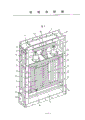
Fig. 1 is the perspective view of electrostatic precipitator structure of the present invention.
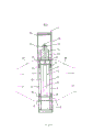
Fig. 2 is the sectional side view of electrostatic precipitator of the present invention.
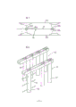
Fig. 3 is the perspective view of discharge cell shown in Figure 1.
Fig. 4 is the perspective view of the another kind of embodiment of discharge cell.
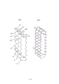
Fig. 5 is used for illustrating hammering device.
Fig. 6 is the key diagram that electrostatic precipitator of the present invention is linked to be a row.
Fig. 7 is the plane of the conventional electrostatic precipitator of expression.
Fig. 8 is the perspective view of the electrostatic precipitator of the another kind of routine of expression.
One embodiment of the present of invention are illustrated with reference to Fig. 1 to Fig. 6.In addition, identical label is represented identical or corresponding parts among Fig. 1 to Fig. 6.
Shown in overall perspective view 1 and sectional side view 2, in fact electrostatic precipitator 1 of the present invention consists of the following components: a discharge portion 2, its installation site with have gas passage to be clean to meet at right angles; A plurality of control of dust parts 3, the front and back of this part and discharge portion 2 are from a distance, and are and parallel with discharge portion 2; A high pressure applying unit 4 that is formed in the discharge portion 2; And a dust-collecting cavity 5 that is formed on the lower of control of dust part 3, discharge portion 2, control of dust part 3, high pressure applying unit 4 and dust-collecting cavity 5 are assembled into an integral body by framework 6.
In addition, owing to the opening portion of air inlet 27 and exhaust outlet 28 and the sealed beam 8 that surrounds the periphery of control of dust part 3 with tetragonal formula connect together, so all there is gas to be clean all to pass through control of dust part 3 and discharge portion 2.So just might solve the dust problem of short-circuit, this is a difficult problem in traditional electrostatic precipitator.
In the discharge portion 2 that so constitutes, because the whole surface distributed of zigzag part 26 close discharge portions 2, so produce corona discharge heap of times from the tip of zigzag part 26, and make the highfield homogenising, so just formed the efficient discharge part.
Here being noted that the shape of sparking electrode is not limited to the shape of zigzag part 26 shown in Figure 3, also can be zigzag shown in Figure 4.In addition, though not shown, lead also can be used as sparking electrode.
Control of dust part 3 is made of collecting electrode 10, and plate and support frame 9 with drilled hole of high boring rate are fixed on the collecting electrode 10, as shown in Figure 1.Here be noted that among Fig. 1 the collecting electrode plate in hole that has been drilled, but resembling the penetrable parts of gas such as woven wire, grid also is acceptable.
When between discharge portion 2 of so constructing and control of dust part 3, adding high voltage, and when the polarity that makes discharge portion 2 is negative, produced unnumbered corona discharge between the tip of each zigzag part 26 of the zigzag discharge electrode 23 in discharge portion 2 and the collecting electrode 10 of control of dust part 3, this part becomes very strong live part.When comprising undesirable material and send into air inlet 27 as having of dust and various bacterium gas to be clean by direction shown in Fig. 2 arrow, the bore portion branch that has gas to be clean to pass the collecting electrode 10 of control of dust part 3 flows to discharge portion 2.At this time, produced corona discharge owing to be close to the tip of each zigzag part 26 of the zigzag discharge electrode 23 in the discharge portion 2 and the collecting electrode of control of dust part 3, so have dust and various bacterium in the gas to be clean between control of dust part 3 and discharge portion 2, to be with negative electricity.So charged dust and various bacterium are repelled by electronegative discharge portion 2, attract and be grounded the control of dust part 3 that forms positive electrode.
Previously described is when discharge portion 2 as the situation of negative electrode, but when discharge portion 2 as positive electrode, control of dust part 3 is as negative electrode, when dust in the gas to be clean and various bacterium positively charged are arranged, also similar phenomenon can take place.
The result, when being present in the dust that has in the gas to be clean and various bacterium when discharge portion 2 passes control of dust part 3, will be charged, they are adsorbed on the collecting electrode 10, becoming becomes dust granule greatly, and the effect by charged particles, it is big that the particle of absorption becomes, and then become dust group.Dust and various bacterium become dust group, then according to kinetic energy be suppressed and by himself weight by there being air-flow to be clean to remove, can not flow out from the outlet side of the gas that purifies.
A pipe 13 is arranged around the supporting rod 14 of high voltage applying unit 4, and stoping by means of the air pressure in the pipe 13 has gas to be clean to flow out along support stick 14.Be positioned at the label 12 that supports angle bar 16 central authorities and represent an insulator, be used for opening with the cabinet insulation of ground connection having applied high-tension support angle bar 16.Label 21 is represented an access door, is used for safeguarding and the control purpose.
Hammering rod 11 is used to remove the dust group that is adsorbed on the control of dust part 3, installs on the support frame 9, leaves certain clearance, and the end nipple of hammering rod 11 is for outside the casing.By hammering device shown in Figure 5 49, with the end that the constant time interval is beaten hammering rod 11, support frame 9 is clashed into, so that remove the dust group that is adsorbed on the collecting electrode 10.
The dust group that is subjected to hammering device 49 vibrations breaks away from control of dust part 3, and owing to own wt falls, is collected by dust-collecting cavity 5.After dust group runs up to a certain degree in dust-collecting cavity 5, get the casing outside by pulling dust export 19 and with it, dust group promptly is removed.In this case, remove dust group and finish, also can remove dust group automatically in dust-collecting cavity 5 by an auger conveyor is provided by manual operation.
Fig. 5 is used for illustrating hammering device 49.Label 41 representatives are contained in the drive motor of the hammering device of casing 29 outsides, and this motor also makes drive pulley 42 rotations.By belt 43, belt pulley 44 is passed in the rotation of drive pulley 42.A camshaft 45 is fixed in the center of belt pulley 44, and cam 46 links to each other with camshaft 45, and cam 46 rotates synchronously with belt pulley 44.When cam 46 periodic rotary, the top and the cam 46 that are fixed on the hammer 47 of hammer support component 48 supports on the casing 29 collide mutually, shake hammer 47 whereby, beat the outer end of hammering rod 11 like this with the constant time interval, control of dust part 3 is clashed into.
Fig. 6 represents one embodiment of the present of invention, and electrostatic precipitator 1 wherein of the present invention is arranged in a row between air inlet 27 and exhaust outlet 28, installs by 7 fens level Four of assembly flange dish.If have dust and various bacterial load amount in the gas to be clean very big, by electrostatic precipitator 1 is linked to be a row as mentioned above, still may improve dust catching efficiency so.
In the above embodiment of the present invention, the dry cleaning method of collecting electrode has been described, certainly, also can combine a kind of system and water spray at intermittence (intermittently cleaning) system of making current continuously flow into collecting electrode (wet system) respectively, to substitute dry cleaning.
Structure of the present invention as mentioned above, sparking electrode intersects with gas passage to be clean is arranged.Therefore, just might be in order to strengthen the unit are that gas to be clean passes the net sectional area of electrostatic precipitator, and sparking electrode is installed arbitrarily, also might cause a strong uniform electric field for gas to be clean is arranged, so that produce a very effective live part, improve dust catching efficiency whereby and significantly.In addition, owing to almost do not have reverse charged particle to be adsorbed on the sparking electrode,, and remove the hammering device of the reverse charged particle of absorption and also do not needed by knocking sparking electrode so dust catching efficiency does not reduce.Like this, just might reduce cost.In addition and since the cleaning control of dust partly the hammering device of usefulness be installed in as the outside of the casing of gas passage to be clean is arranged, hammering device just can not be subjected to the infringement of dust, so make regular maintenance simple.Moreover, owing to become an integral installation on framework as the discharge portion of the major part of electrostatic precipitator and control of dust part and high voltage applying unit, dust-collecting cavity, so when dressing up a row according to the load that gas to be clean is arranged and with electrostatic precipitator of the present invention, production process has also become simply.
Claims (2)
1, a kind of electrostatic precipitator, it comprises the discharge portion and a plurality of control of dust part with the penetrable structure of gas that are arranged in casing, discharge portion intersects with gas passage to be clean is arranged, make from air inlet and send into, from having of discharging of exhaust outlet to be clean comprise unwanted gas sensing such as dust and various bacterial components charged, dust collecting part is divided parallel mutually, with the front and back of described discharge portion from a distance, it is characterized in that, a high voltage applying unit is arranged in the described discharge portion, there is a dust-collecting cavity lower of described control of dust part, described discharge portion, the control of dust part, high voltage applying unit and dust-collecting cavity are contained in the framework, constitute an integral body, by the assembly flange dish that provides on the described framework circumferential surface, described electrostatic precipitator can freely be assembled into a row.
2, electrostatic precipitator as claimed in claim 1, it is characterized in that, be provided with a hammer of hammering device, be used to remove the undesirable material that is adsorbed on each control of dust that all has the penetrable structure of gas part, and by the protruding casing in outer end of the hammering rod of described hammer hammering.
Applications Claiming Priority (2)
| Application Number | Priority Date | Filing Date | Title |
|---|---|---|---|
| JP216347/91 | 1991-08-02 | ||
| JP21634791A JP3211032B2 (en) | 1991-08-02 | 1991-08-02 | Electric dust collector |
Publications (2)
| Publication Number | Publication Date |
|---|---|
| CN1069209A true CN1069209A (en) | 1993-02-24 |
| CN1033007C CN1033007C (en) | 1996-10-16 |
Family
ID=16687133
Family Applications (1)
| Application Number | Title | Priority Date | Filing Date |
|---|---|---|---|
| CN92102802A Expired - Fee Related CN1033007C (en) | 1991-08-02 | 1992-04-18 | Electrostatic precipitator |
Country Status (10)
| Country | Link |
|---|---|
| US (1) | US5248324A (en) |
| EP (1) | EP0525283B1 (en) |
| JP (1) | JP3211032B2 (en) |
| KR (1) | KR0167791B1 (en) |
| CN (1) | CN1033007C (en) |
| AU (1) | AU652415B2 (en) |
| CA (1) | CA2064440C (en) |
| CZ (1) | CZ279716B6 (en) |
| DE (1) | DE69214374T2 (en) |
| SK (1) | SK130492A3 (en) |
Cited By (1)
| Publication number | Priority date | Publication date | Assignee | Title |
|---|---|---|---|---|
| CN111009587A (en) * | 2019-11-25 | 2020-04-14 | 湖南红太阳新能源科技有限公司 | A photovoltaic module for atmospheric environment restoration and power generation reuse |
Families Citing this family (57)
| Publication number | Priority date | Publication date | Assignee | Title |
|---|---|---|---|---|
| JPH0710412U (en) * | 1993-07-12 | 1995-02-14 | 長利 鈴木 | Gas purification equipment |
| JP3358008B2 (en) * | 1994-01-31 | 2002-12-16 | 株式会社エルデック | Electric dust collector |
| JP3427165B2 (en) * | 1994-02-24 | 2003-07-14 | 株式会社エルデック | Electric dust collector |
| JPH07328475A (en) * | 1994-06-07 | 1995-12-19 | Keiichi Hara | Electric precipitator |
| US6544485B1 (en) * | 2001-01-29 | 2003-04-08 | Sharper Image Corporation | Electro-kinetic device with enhanced anti-microorganism capability |
| US6176977B1 (en) * | 1998-11-05 | 2001-01-23 | Sharper Image Corporation | Electro-kinetic air transporter-conditioner |
| US6350417B1 (en) | 1998-11-05 | 2002-02-26 | Sharper Image Corporation | Electrode self-cleaning mechanism for electro-kinetic air transporter-conditioner devices |
| US6632407B1 (en) | 1998-11-05 | 2003-10-14 | Sharper Image Corporation | Personal electro-kinetic air transporter-conditioner |
| US6974560B2 (en) * | 1998-11-05 | 2005-12-13 | Sharper Image Corporation | Electro-kinetic air transporter and conditioner device with enhanced anti-microorganism capability |
| US20030206837A1 (en) | 1998-11-05 | 2003-11-06 | Taylor Charles E. | Electro-kinetic air transporter and conditioner device with enhanced maintenance features and enhanced anti-microorganism capability |
| US20050210902A1 (en) | 2004-02-18 | 2005-09-29 | Sharper Image Corporation | Electro-kinetic air transporter and/or conditioner devices with features for cleaning emitter electrodes |
| US6911186B2 (en) * | 1998-11-05 | 2005-06-28 | Sharper Image Corporation | Electro-kinetic air transporter and conditioner device with enhanced housing configuration and enhanced anti-microorganism capability |
| US7695690B2 (en) | 1998-11-05 | 2010-04-13 | Tessera, Inc. | Air treatment apparatus having multiple downstream electrodes |
| US20020146356A1 (en) * | 1998-11-05 | 2002-10-10 | Sinaiko Robert J. | Dual input and outlet electrostatic air transporter-conditioner |
| US20020127156A1 (en) * | 1998-11-05 | 2002-09-12 | Taylor Charles E. | Electro-kinetic air transporter-conditioner devices with enhanced collector electrode |
| US7318856B2 (en) | 1998-11-05 | 2008-01-15 | Sharper Image Corporation | Air treatment apparatus having an electrode extending along an axis which is substantially perpendicular to an air flow path |
| US20020155041A1 (en) * | 1998-11-05 | 2002-10-24 | Mckinney Edward C. | Electro-kinetic air transporter-conditioner with non-equidistant collector electrodes |
| US7220295B2 (en) | 2003-05-14 | 2007-05-22 | Sharper Image Corporation | Electrode self-cleaning mechanisms with anti-arc guard for electro-kinetic air transporter-conditioner devices |
| US6224653B1 (en) * | 1998-12-29 | 2001-05-01 | Pulsatron Technology Corporation | Electrostatic method and means for removing contaminants from gases |
| FI105259B (en) * | 1999-03-02 | 2000-07-14 | Flaekt Ab | electrostatic precipitators |
| US6749667B2 (en) | 2002-06-20 | 2004-06-15 | Sharper Image Corporation | Electrode self-cleaning mechanism for electro-kinetic air transporter-conditioner devices |
| US7056370B2 (en) | 2002-06-20 | 2006-06-06 | Sharper Image Corporation | Electrode self-cleaning mechanism for air conditioner devices |
| US7405672B2 (en) | 2003-04-09 | 2008-07-29 | Sharper Image Corp. | Air treatment device having a sensor |
| US6984987B2 (en) | 2003-06-12 | 2006-01-10 | Sharper Image Corporation | Electro-kinetic air transporter and conditioner devices with enhanced arching detection and suppression features |
| US20050028676A1 (en) * | 2003-08-05 | 2005-02-10 | Heckel Scott P. | Corona discharge electrode assembly for electrostatic precipitator |
| US7906080B1 (en) | 2003-09-05 | 2011-03-15 | Sharper Image Acquisition Llc | Air treatment apparatus having a liquid holder and a bipolar ionization device |
| US20050051420A1 (en) | 2003-09-05 | 2005-03-10 | Sharper Image Corporation | Electro-kinetic air transporter and conditioner devices with insulated driver electrodes |
| US7724492B2 (en) | 2003-09-05 | 2010-05-25 | Tessera, Inc. | Emitter electrode having a strip shape |
| US7077890B2 (en) | 2003-09-05 | 2006-07-18 | Sharper Image Corporation | Electrostatic precipitators with insulated driver electrodes |
| US7517503B2 (en) | 2004-03-02 | 2009-04-14 | Sharper Image Acquisition Llc | Electro-kinetic air transporter and conditioner devices including pin-ring electrode configurations with driver electrode |
| US7767169B2 (en) | 2003-12-11 | 2010-08-03 | Sharper Image Acquisition Llc | Electro-kinetic air transporter-conditioner system and method to oxidize volatile organic compounds |
| CA2555603C (en) * | 2004-02-11 | 2012-04-03 | Jean-Pierre Lepage | System for treating contaminated gas |
| US7638104B2 (en) | 2004-03-02 | 2009-12-29 | Sharper Image Acquisition Llc | Air conditioner device including pin-ring electrode configurations with driver electrode |
| US20060016333A1 (en) | 2004-07-23 | 2006-01-26 | Sharper Image Corporation | Air conditioner device with removable driver electrodes |
| US7311762B2 (en) | 2004-07-23 | 2007-12-25 | Sharper Image Corporation | Air conditioner device with a removable driver electrode |
| US7285155B2 (en) | 2004-07-23 | 2007-10-23 | Taylor Charles E | Air conditioner device with enhanced ion output production features |
| US7241330B2 (en) * | 2004-10-25 | 2007-07-10 | Oreck Holdings, Llc | Air cleaner electrostatic precipitator cell |
| US7368002B2 (en) * | 2005-02-14 | 2008-05-06 | Mcdonnell Joseph A | Ionic air conditioning system |
| WO2006086886A1 (en) * | 2005-02-18 | 2006-08-24 | Turbosonic Inc. | Mast electrode design |
| NO323806B1 (en) * | 2005-11-01 | 2007-07-09 | Roger Gale | Entrance electrostatic stove precipitator |
| US20070151448A1 (en) * | 2006-01-04 | 2007-07-05 | Robert Taylor | Discharge electrode and method for enhancement of an electrostatic precipitator |
| US20090139406A1 (en) * | 2006-01-04 | 2009-06-04 | General Electric Company | Discharge electrode and method for enhancement of an electrostatic precipitator |
| KR100722863B1 (en) * | 2006-02-28 | 2007-05-30 | 에어텍21 주식회사 | Collector cell unit of electric dust collector |
| US7833322B2 (en) | 2006-02-28 | 2010-11-16 | Sharper Image Acquisition Llc | Air treatment apparatus having a voltage control device responsive to current sensing |
| KR100658822B1 (en) * | 2006-10-10 | 2006-12-15 | 로얄정보기술 주식회사 | Subway station air purification ventilation system |
| BR112013024727B1 (en) | 2011-03-28 | 2021-01-19 | Megtec Turbosonic Inc. | collection electrode for a wet electrostatic precipitator |
| US11027289B2 (en) | 2011-12-09 | 2021-06-08 | Durr Systems Inc. | Wet electrostatic precipitator system components |
| CN104271248B (en) * | 2012-07-31 | 2016-10-05 | 富士电机株式会社 | Electric dust collector |
| WO2014035477A1 (en) | 2012-08-27 | 2014-03-06 | Energy & Environmental Research Center Foundation | Staged electrostatic precipitator |
| JP5735188B1 (en) * | 2013-06-06 | 2015-06-17 | 東京博善株式会社 | Cremation system |
| CN103868154B (en) * | 2014-03-21 | 2016-03-30 | 宁波东大空调设备有限公司 | A kind of semi-enclosed air-conditioning companion air purifier |
| CN103909015A (en) * | 2014-04-01 | 2014-07-09 | 安徽博隆机械制造有限公司 | Synergistic electrostatic dust collection method |
| CN104492600B (en) * | 2014-12-17 | 2017-06-06 | 浙江金海环境技术股份有限公司 | Electrostatic precipitator and its manufacture method and purposes |
| DE102016202293B3 (en) * | 2016-02-15 | 2017-04-27 | Wilhelm Bruckbauer | Device for arranging one or more electrodes of a plasma filter in a housing |
| WO2019039205A1 (en) * | 2017-08-25 | 2019-02-28 | パナソニックIpマネジメント株式会社 | Dust collector |
| JP7109194B2 (en) | 2018-01-15 | 2022-07-29 | 三菱重工パワー環境ソリューション株式会社 | Electrostatic precipitator |
| WO2021187801A1 (en) * | 2020-03-18 | 2021-09-23 | Samsung Electronics Co., Ltd. | Electrostatic dust collecting apparatus and method of manufacturing the same |
Family Cites Families (16)
| Publication number | Priority date | Publication date | Assignee | Title |
|---|---|---|---|---|
| DE544384C (en) * | 1932-02-17 | Telex Appbau Ges M B H | Dust collection and discharge channels for spray electrodes of electrostatic precipitators | |
| GB167939A (en) * | 1920-06-29 | 1921-08-25 | Int Precipitation Co | Improvements in apparatus for electrical treatment of gases |
| CH109892A (en) * | 1924-05-14 | 1925-05-16 | Minami Manshu Tetsudo Kabushik | Installation for intercepting and recovering dust in suspension in certain gases such as, for example, the smoke emitted by industrial furnaces. |
| US1882949A (en) * | 1930-11-15 | 1932-10-18 | Int Precipitation Co | Electrical precipitation apparatus |
| US1912053A (en) * | 1931-06-15 | 1933-05-30 | Research Corp | Electrical precipitator |
| US2063391A (en) * | 1934-12-29 | 1936-12-08 | Standard Oil Co | Electrode mounting |
| DE752201C (en) * | 1942-11-12 | 1953-05-18 | Siemens Lurgi Cottrell Elektro | Small electrostatic precipitator with removable treatment zones |
| US3086341A (en) * | 1959-11-04 | 1963-04-23 | Brandt Herbert | Shaking device for electric filters and a method for operating same |
| US3729815A (en) * | 1971-01-25 | 1973-05-01 | Koppers Co Inc | Method for installing multiples of dust collector plates |
| AU470598B2 (en) * | 1971-06-21 | 1976-03-25 | Email Westinghouse Pty. Limited | Electrostatic precipitator |
| US4026684A (en) * | 1975-09-15 | 1977-05-31 | Klykon, Inc. | Air filtration cassette with electrostatic precipitator and having multiple filter elements |
| US4526591A (en) * | 1982-12-13 | 1985-07-02 | Allis-Chalmers Corporation | Electrode rapping arrangement |
| DE3622699A1 (en) * | 1986-07-05 | 1988-01-14 | Metallgesellschaft Ag | ELECTROSTATIC DUST SEPARATOR |
| JPS63171655A (en) * | 1986-12-31 | 1988-07-15 | Keiichi Hara | Electrostatic precipitator |
| JPH0694010B2 (en) * | 1986-12-31 | 1994-11-24 | 株式会社日本フィルトレーション | Electric dust collector |
| SE462421B (en) * | 1988-11-04 | 1990-06-25 | Boliden Contech Ab | DEVICE OF WATER ELECTROFILTER |
-
1991
- 1991-08-02 JP JP21634791A patent/JP3211032B2/en not_active Expired - Lifetime
-
1992
- 1992-02-18 US US07/835,867 patent/US5248324A/en not_active Expired - Lifetime
- 1992-02-20 AU AU11118/92A patent/AU652415B2/en not_active Ceased
- 1992-02-25 DE DE69214374T patent/DE69214374T2/en not_active Expired - Fee Related
- 1992-02-25 EP EP92103155A patent/EP0525283B1/en not_active Expired - Lifetime
- 1992-03-30 CA CA002064440A patent/CA2064440C/en not_active Expired - Fee Related
- 1992-04-18 CN CN92102802A patent/CN1033007C/en not_active Expired - Fee Related
- 1992-04-29 CZ CS921304A patent/CZ279716B6/en not_active IP Right Cessation
- 1992-04-29 SK SK1304-92A patent/SK130492A3/en unknown
- 1992-05-09 KR KR1019920007880A patent/KR0167791B1/en not_active Expired - Fee Related
Cited By (2)
| Publication number | Priority date | Publication date | Assignee | Title |
|---|---|---|---|---|
| CN111009587A (en) * | 2019-11-25 | 2020-04-14 | 湖南红太阳新能源科技有限公司 | A photovoltaic module for atmospheric environment restoration and power generation reuse |
| CN111009587B (en) * | 2019-11-25 | 2021-05-14 | 湖南红太阳新能源科技有限公司 | Photovoltaic module for atmospheric environment restoration and power generation multiplexing |
Also Published As
| Publication number | Publication date |
|---|---|
| KR0167791B1 (en) | 1999-01-15 |
| CA2064440A1 (en) | 1993-02-03 |
| SK277812B6 (en) | 1995-03-08 |
| JPH0531399A (en) | 1993-02-09 |
| EP0525283A1 (en) | 1993-02-03 |
| CZ130492A3 (en) | 1993-02-17 |
| KR930003965A (en) | 1993-03-22 |
| SK130492A3 (en) | 1995-03-08 |
| DE69214374D1 (en) | 1996-11-14 |
| JP3211032B2 (en) | 2001-09-25 |
| CA2064440C (en) | 1998-09-01 |
| EP0525283B1 (en) | 1996-10-09 |
| AU652415B2 (en) | 1994-08-25 |
| AU1111892A (en) | 1993-02-04 |
| US5248324A (en) | 1993-09-28 |
| CN1033007C (en) | 1996-10-16 |
| CZ279716B6 (en) | 1995-06-14 |
| DE69214374T2 (en) | 1997-03-06 |
Similar Documents
| Publication | Publication Date | Title |
|---|---|---|
| CN1033007C (en) | Electrostatic precipitator | |
| CN1091659C (en) | Electrostatic precipitator | |
| CN1224805C (en) | Air purifier | |
| CN106622669A (en) | Electrode plate module for electrostatic dust collector and electrostatic dust collector | |
| CN105268557B (en) | High-voltage electrostatic dust separator | |
| CN108160332B (en) | Electric dust collector with filtering type porous anode plate | |
| CN102172564A (en) | Revolving body electrode and heterogeneous separation device based on same | |
| KR102311176B1 (en) | Bi-directional electric dust collecting module including pin type discharge plate | |
| KR20210095264A (en) | Bi-directional fine dust hexagonal tube dust collecting module with snow crystal ionizer | |
| US20080295694A1 (en) | Tunnel Fan Electrostatic Filter | |
| KR20230167992A (en) | Dust collection system that improves cleaning efficiency | |
| CA1051359A (en) | Swing hammer rapping system for electrostatic precipitator | |
| KR102699323B1 (en) | Electrostatic precipitator using non-metallic dust collecting plate with added charging function | |
| JPH07232099A (en) | Electric precipitator | |
| JP6684986B2 (en) | Electric dust collector | |
| CN2752648Y (en) | Mechanical electrostatic combined cooking fumes purifier | |
| CN1542347A (en) | Ionization portion arrangement for electronic dust collection filter | |
| KR0134484Y1 (en) | Fixing apparatus for collecting plate in electrostatic precipitator | |
| KR20000000179U (en) | Rigid Body Electrode Frame for Electrostatic Precipitator | |
| KR20050119843A (en) | Air purifier | |
| JPH07313902A (en) | Electric precipitator | |
| KR19990033864U (en) | Multi-Wire Electrostatic Precipitator |
Legal Events
| Date | Code | Title | Description |
|---|---|---|---|
| C06 | Publication | ||
| PB01 | Publication | ||
| C10 | Entry into substantive examination | ||
| SE01 | Entry into force of request for substantive examination | ||
| C14 | Grant of patent or utility model | ||
| GR01 | Patent grant | ||
| C53 | Correction of patent of invention or patent application | ||
| COR | Change of bibliographic data |
Free format text: CORRECT: PATENTEE; FROM: JAPAN FILTRATION CO., LTD. TO: YAMAGATA COUNTY, JAPAN |
|
| CP01 | Change in the name or title of a patent holder |
Patentee after: Yamagata Prefecture, Japan Patentee before: Japan filtration KK |
|
| C15 | Extension of patent right duration from 15 to 20 years for appl. with date before 31.12.1992 and still valid on 11.12.2001 (patent law change 1993) | ||
| OR01 | Other related matters | ||
| C19 | Lapse of patent right due to non-payment of the annual fee | ||
| CF01 | Termination of patent right due to non-payment of annual fee |