CN106921390B - Frequency synthesizer and frequency synthesizing method - Google Patents
Frequency synthesizer and frequency synthesizing method Download PDFInfo
- Publication number
- CN106921390B CN106921390B CN201610055823.3A CN201610055823A CN106921390B CN 106921390 B CN106921390 B CN 106921390B CN 201610055823 A CN201610055823 A CN 201610055823A CN 106921390 B CN106921390 B CN 106921390B
- Authority
- CN
- China
- Prior art keywords
- frequency
- locked loop
- phase
- loop
- output
- Prior art date
- Legal status (The legal status is an assumption and is not a legal conclusion. Google has not performed a legal analysis and makes no representation as to the accuracy of the status listed.)
- Active
Links
Images


Classifications
-
- H—ELECTRICITY
- H03—ELECTRONIC CIRCUITRY
- H03L—AUTOMATIC CONTROL, STARTING, SYNCHRONISATION OR STABILISATION OF GENERATORS OF ELECTRONIC OSCILLATIONS OR PULSES
- H03L7/00—Automatic control of frequency or phase; Synchronisation
- H03L7/06—Automatic control of frequency or phase; Synchronisation using a reference signal applied to a frequency- or phase-locked loop
- H03L7/16—Indirect frequency synthesis, i.e. generating a desired one of a number of predetermined frequencies using a frequency- or phase-locked loop
- H03L7/18—Indirect frequency synthesis, i.e. generating a desired one of a number of predetermined frequencies using a frequency- or phase-locked loop using a frequency divider or counter in the loop
- H03L7/183—Indirect frequency synthesis, i.e. generating a desired one of a number of predetermined frequencies using a frequency- or phase-locked loop using a frequency divider or counter in the loop a time difference being used for locking the loop, the counter counting between fixed numbers or the frequency divider dividing by a fixed number
- H03L7/185—Indirect frequency synthesis, i.e. generating a desired one of a number of predetermined frequencies using a frequency- or phase-locked loop using a frequency divider or counter in the loop a time difference being used for locking the loop, the counter counting between fixed numbers or the frequency divider dividing by a fixed number using a mixer in the loop
-
- H—ELECTRICITY
- H03—ELECTRONIC CIRCUITRY
- H03L—AUTOMATIC CONTROL, STARTING, SYNCHRONISATION OR STABILISATION OF GENERATORS OF ELECTRONIC OSCILLATIONS OR PULSES
- H03L7/00—Automatic control of frequency or phase; Synchronisation
- H03L7/06—Automatic control of frequency or phase; Synchronisation using a reference signal applied to a frequency- or phase-locked loop
- H03L7/16—Indirect frequency synthesis, i.e. generating a desired one of a number of predetermined frequencies using a frequency- or phase-locked loop
- H03L7/22—Indirect frequency synthesis, i.e. generating a desired one of a number of predetermined frequencies using a frequency- or phase-locked loop using more than one loop
- H03L7/23—Indirect frequency synthesis, i.e. generating a desired one of a number of predetermined frequencies using a frequency- or phase-locked loop using more than one loop with pulse counters or frequency dividers
-
- H—ELECTRICITY
- H03—ELECTRONIC CIRCUITRY
- H03L—AUTOMATIC CONTROL, STARTING, SYNCHRONISATION OR STABILISATION OF GENERATORS OF ELECTRONIC OSCILLATIONS OR PULSES
- H03L7/00—Automatic control of frequency or phase; Synchronisation
- H03L7/06—Automatic control of frequency or phase; Synchronisation using a reference signal applied to a frequency- or phase-locked loop
- H03L7/08—Details of the phase-locked loop
- H03L7/085—Details of the phase-locked loop concerning mainly the frequency- or phase-detection arrangement including the filtering or amplification of its output signal
- H03L7/089—Details of the phase-locked loop concerning mainly the frequency- or phase-detection arrangement including the filtering or amplification of its output signal the phase or frequency detector generating up-down pulses
- H03L7/0891—Details of the phase-locked loop concerning mainly the frequency- or phase-detection arrangement including the filtering or amplification of its output signal the phase or frequency detector generating up-down pulses the up-down pulses controlling source and sink current generators, e.g. a charge pump
-
- H—ELECTRICITY
- H03—ELECTRONIC CIRCUITRY
- H03L—AUTOMATIC CONTROL, STARTING, SYNCHRONISATION OR STABILISATION OF GENERATORS OF ELECTRONIC OSCILLATIONS OR PULSES
- H03L7/00—Automatic control of frequency or phase; Synchronisation
- H03L7/06—Automatic control of frequency or phase; Synchronisation using a reference signal applied to a frequency- or phase-locked loop
- H03L7/16—Indirect frequency synthesis, i.e. generating a desired one of a number of predetermined frequencies using a frequency- or phase-locked loop
- H03L7/18—Indirect frequency synthesis, i.e. generating a desired one of a number of predetermined frequencies using a frequency- or phase-locked loop using a frequency divider or counter in the loop
- H03L7/197—Indirect frequency synthesis, i.e. generating a desired one of a number of predetermined frequencies using a frequency- or phase-locked loop using a frequency divider or counter in the loop a time difference being used for locking the loop, the counter counting between numbers which are variable in time or the frequency divider dividing by a factor variable in time, e.g. for obtaining fractional frequency division
- H03L7/1974—Indirect frequency synthesis, i.e. generating a desired one of a number of predetermined frequencies using a frequency- or phase-locked loop using a frequency divider or counter in the loop a time difference being used for locking the loop, the counter counting between numbers which are variable in time or the frequency divider dividing by a factor variable in time, e.g. for obtaining fractional frequency division for fractional frequency division
-
- H—ELECTRICITY
- H03—ELECTRONIC CIRCUITRY
- H03L—AUTOMATIC CONTROL, STARTING, SYNCHRONISATION OR STABILISATION OF GENERATORS OF ELECTRONIC OSCILLATIONS OR PULSES
- H03L7/00—Automatic control of frequency or phase; Synchronisation
- H03L7/06—Automatic control of frequency or phase; Synchronisation using a reference signal applied to a frequency- or phase-locked loop
- H03L7/16—Indirect frequency synthesis, i.e. generating a desired one of a number of predetermined frequencies using a frequency- or phase-locked loop
- H03L7/18—Indirect frequency synthesis, i.e. generating a desired one of a number of predetermined frequencies using a frequency- or phase-locked loop using a frequency divider or counter in the loop
- H03L7/197—Indirect frequency synthesis, i.e. generating a desired one of a number of predetermined frequencies using a frequency- or phase-locked loop using a frequency divider or counter in the loop a time difference being used for locking the loop, the counter counting between numbers which are variable in time or the frequency divider dividing by a factor variable in time, e.g. for obtaining fractional frequency division
- H03L7/1974—Indirect frequency synthesis, i.e. generating a desired one of a number of predetermined frequencies using a frequency- or phase-locked loop using a frequency divider or counter in the loop a time difference being used for locking the loop, the counter counting between numbers which are variable in time or the frequency divider dividing by a factor variable in time, e.g. for obtaining fractional frequency division for fractional frequency division
- H03L7/1976—Indirect frequency synthesis, i.e. generating a desired one of a number of predetermined frequencies using a frequency- or phase-locked loop using a frequency divider or counter in the loop a time difference being used for locking the loop, the counter counting between numbers which are variable in time or the frequency divider dividing by a factor variable in time, e.g. for obtaining fractional frequency division for fractional frequency division using a phase accumulator for controlling the counter or frequency divider
-
- H—ELECTRICITY
- H04—ELECTRIC COMMUNICATION TECHNIQUE
- H04B—TRANSMISSION
- H04B1/00—Details of transmission systems, not covered by a single one of groups H04B3/00 - H04B13/00; Details of transmission systems not characterised by the medium used for transmission
- H04B1/38—Transceivers, i.e. devices in which transmitter and receiver form a structural unit and in which at least one part is used for functions of transmitting and receiving
- H04B1/40—Circuits
Landscapes
- Engineering & Computer Science (AREA)
- Computer Networks & Wireless Communication (AREA)
- Signal Processing (AREA)
- Stabilization Of Oscillater, Synchronisation, Frequency Synthesizers (AREA)
Abstract
一种频率合成器及频率合成方法,该频率合成器包括:辅助锁相回路以及主要锁相回路,其中,辅助锁相回路通过调整其可调式非整数分频器的除数,以输出所有频带的最大频带的通道频率,主要锁相回路通过调整其可调式整数分频器的除数,以输出该所有频带中每一个频带所需的中心频率,接着,利用混波器混合该中心频率与该通道频率以产生频带频率,且该可调式非整数分频器所产生的量化噪声经该辅助锁相回路滤波后,可降低其对主要锁相回路的影响。
A frequency synthesizer and a frequency synthesis method. The frequency synthesizer includes: an auxiliary phase locked loop and a main phase locked loop. The auxiliary phase locked loop adjusts the divisor of its adjustable non-integer frequency divider to output all frequency bands. The channel frequency of the maximum frequency band, the main phase locked loop adjusts the divisor of its adjustable integer divider to output the required center frequency of each of all frequency bands, and then uses a mixer to mix the center frequency with the channel The frequency is to generate a band frequency, and the quantization noise generated by the adjustable non-integer frequency divider can be filtered by the auxiliary phase locked loop to reduce its impact on the main phase locked loop.
Description
技术领域technical field
本公开涉及尤指一种具有双回路锁相回路的频率合成器及频率合成方法。The present disclosure relates, in particular, to a frequency synthesizer with a dual-loop phase-locked loop and a frequency synthesis method.
背景技术Background technique
由于无线通信技术的进步,便携式通信装置广为人们使用,移动宽频市场逐渐成长,为了因应更大量的数据传输需求,如何有效提升传输速度及带宽变成为新一代移动通信的课题。Due to the advancement of wireless communication technology, portable communication devices are widely used, and the mobile broadband market is gradually growing. In order to meet the demand for greater data transmission, how to effectively improve the transmission speed and bandwidth has become a new generation of mobile communication issues.
近年来3GPP(3rd Generation Partnership Project)致力于发展符合4G通信协议的技术,并提出长时间进阶演进技术(The Long-term Evolution-Advanced,LTE-A)第十版本(Release 10,R10),也为第一个被国际电信联盟承认的4G标准,其数据传输率在高速移动的环境下可达100(Mb/s)。在LTE-A技术中,载波聚合(Carrier Aggregation)为一个关键技术,其概念是在同一时间将不连续的频段汇整使用,进而获得更大的传输带宽,以提升带宽的使用效率。为了达到载波聚合的目的,无线通信装置中的收发机(RF transceiver)必须动态的改变载波频率。宽广的载波频率范围意味着提供地方频率(Local Frequency)的频率合成器(Frequency Synthesizer)必须拥有极为宽频的输出,但此使得振荡器设计困难,且复杂的带宽条件也对频率合成器的控制及频率解析度提出挑战。In recent years, the 3GPP (3rd Generation Partnership Project) has been committed to the development of technologies that conform to 4G communication protocols, and proposed The Long-term Evolution-Advanced (LTE-A) tenth release (Release 10, R10), It is also the first 4G standard recognized by the International Telecommunication Union, and its data transmission rate can reach 100 (Mb/s) in a high-speed mobile environment. In LTE-A technology, carrier aggregation (Carrier Aggregation) is a key technology. The concept is to aggregate and use discontinuous frequency bands at the same time, thereby obtaining a larger transmission bandwidth and improving bandwidth utilization efficiency. In order to achieve the purpose of carrier aggregation, a transceiver (RF transceiver) in a wireless communication device must dynamically change the carrier frequency. The wide carrier frequency range means that the frequency synthesizer (Frequency Synthesizer) that provides the local frequency (Local Frequency) must have a very wide frequency output, but this makes the oscillator design difficult, and the complex bandwidth conditions also affect the frequency synthesizer. Frequency resolution presents challenges.
因此,需要提出一种频率合成器技术,期望在得到目标频率外,同时可提供IQ相位,以符合频率输出范围的规格,同时可兼顾频率解析度,实为目前本技术领域人员急迫解决的技术问题。Therefore, it is necessary to propose a frequency synthesizer technology, which is expected to provide the IQ phase in addition to the target frequency, so as to meet the specifications of the frequency output range, and at the same time, the frequency resolution can be taken into account. question.
发明内容SUMMARY OF THE INVENTION
本公开提出一种频率合成器,包含:辅助锁相回路以及主要锁相回路,其中,辅助锁相回路包括可调式非整数分频器,该辅助锁相回路通过调整该可调式非整数分频器的除数,以输出所有频带的最大频带的通道频率,该主要锁相回路包括可调式整数分频器和混波器,以供该主要锁相回路通过调整该可调式整数分频器的除数,输出该所有频带中每一个频带所需的中心频率,且该混波器连接该主要锁相回路的输出端及该辅助锁相回路的输出端,以混合该中心频率与该通道频率而产生频带频率,且其中,该可调式非整数分频器所产生的量化噪声经该辅助锁相回路滤波后,降低对该主要锁相回路的影响。The present disclosure provides a frequency synthesizer, comprising: an auxiliary phase-locked loop and a main phase-locked loop, wherein the auxiliary phase-locked loop includes an adjustable non-integer frequency divider, and the auxiliary phase-locked loop adjusts the adjustable non-integer frequency divider by adjusting the adjustable non-integer frequency divider. The main phase-locked loop includes an adjustable integer frequency divider and a mixer for the main phase-locked loop to adjust the divisor of the adjustable integer frequency divider , output the center frequency required by each frequency band in all frequency bands, and the mixer is connected to the output end of the main phase-locked loop and the output end of the auxiliary phase-locked loop to mix the center frequency and the channel frequency to generate frequency, and wherein the quantization noise generated by the adjustable non-integer frequency divider is filtered by the auxiliary phase-locked loop to reduce the influence on the main phase-locked loop.
本公开还提出一种使用上述频率合成器的无线收发机。The present disclosure also proposes a wireless transceiver using the above frequency synthesizer.
本公开另提出一种频率合成方法,包含:提供具有主要锁相回路以及辅助锁相回路的频率合成器;通过调整该辅助锁相回路的可调式非整数分频器的除数,使该辅助锁相回路输出所有频带的最大频带的通道频率,以及通过调整该主要锁相回路的可调式整数分频器的除数,使该主要锁相回路输出该所有频带中每一个频带所需的中心频率;以及令该主要锁相回路的混波器混合该通道频率与该中心频率,以产生频带频率。The present disclosure further provides a frequency synthesis method, including: providing a frequency synthesizer with a main phase-locked loop and an auxiliary phase-locked loop; The phase loop outputs the channel frequency of the largest frequency band of all frequency bands, and by adjusting the divisor of the adjustable integer frequency divider of the main phase-locked loop, the main phase-locked loop outputs the required center frequency of each of the all frequency bands; and making the mixer of the main phase locked loop mix the channel frequency and the center frequency to generate the frequency band.
相较于现有技术,本公开所提出的频率合成器及频率合成方法,主要由两个锁相回路组成,其中,主要锁相回路使用宽频振荡器来达成宽频输出的需求,辅助锁相回路使用和差调制器来达成高解析度的需求,该主要锁相回路的中心频率与该辅助锁相回路的通道频率经混波器混波后,产生主要锁相回路输出的频带频率,可再经多工器后产生符合频率需求的频率,另外,通过本公开所提出的双回路机制,将有助于大幅降低量化噪声的影响。Compared with the prior art, the frequency synthesizer and the frequency synthesis method proposed in the present disclosure are mainly composed of two phase-locked loops. The sum-difference modulator is used to achieve high-resolution requirements. After the center frequency of the main phase-locked loop and the channel frequency of the auxiliary phase-locked loop are mixed by the mixer, the frequency band output of the main phase-locked loop can be generated again. After the multiplexer, the frequency that meets the frequency requirement is generated. In addition, the double-loop mechanism proposed in the present disclosure will help to greatly reduce the influence of quantization noise.
附图说明Description of drawings
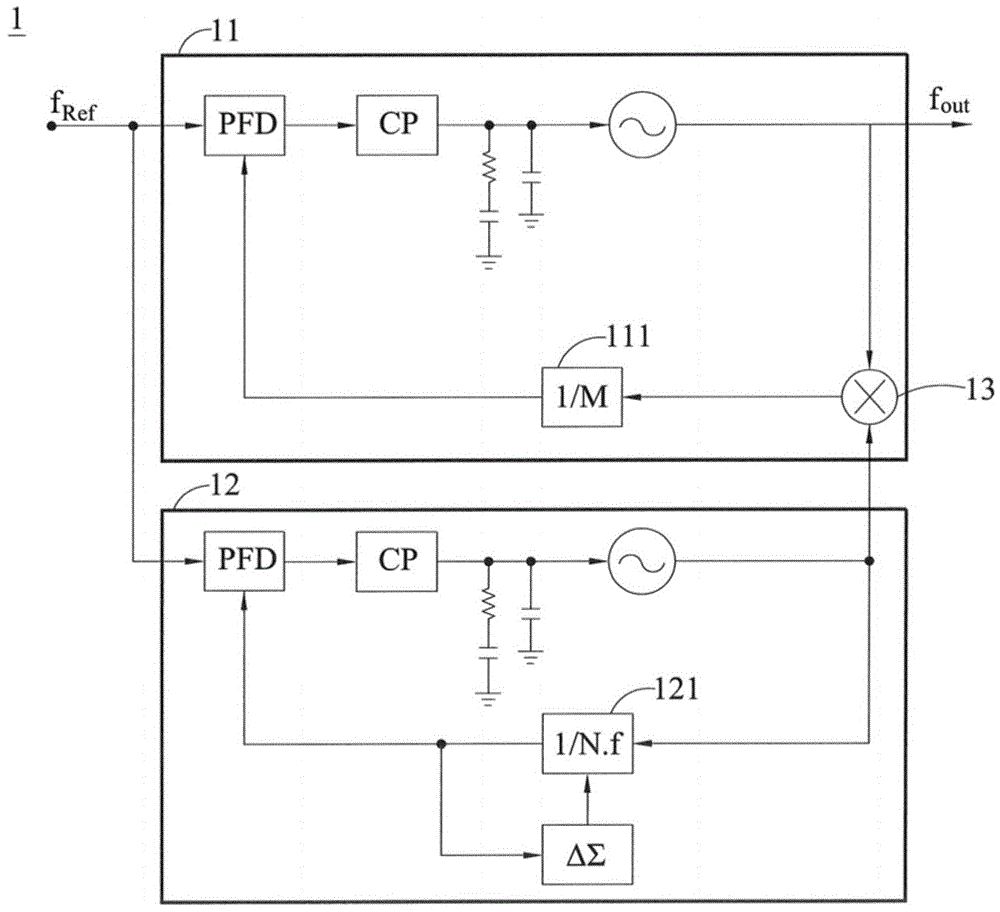
图1为本公开的频率合成器的示意图;1 is a schematic diagram of a frequency synthesizer of the present disclosure;
图2A为本公开的频率合成器第一实施例的示意图;2A is a schematic diagram of a first embodiment of the disclosed frequency synthesizer;
图2B为本公开的频率合成器产生各种频带频率的示意图;2B is a schematic diagram of the frequency synthesizer of the present disclosure generating various frequency bands;
图3为本公开的频率合成器第二实施例的示意图;3 is a schematic diagram of a second embodiment of the disclosed frequency synthesizer;
图4为本公开的频率合成器第三实施例的示意图;以及FIG. 4 is a schematic diagram of a third embodiment of the frequency synthesizer of the present disclosure; and
图5为本公开的频率合成方法的步骤图。FIG. 5 is a step diagram of the frequency synthesis method of the present disclosure.
符号说明Symbol Description
1 频率合成器1 Frequency Synthesizer
11 主要锁相回路11 Main Phase Locked Loop
111 可调式整数分频器111 Adjustable Integer Divider
112 第一相位频率检测器112 First phase frequency detector
113 第一电荷泵113 First charge pump
114 第一回路滤波器114 First loop filter
115 第一压控振荡器115 First VCO
116 第一回路分频器116 First loop divider
12 辅助锁相回路12 Auxiliary PLL
121 可调式非整数分频器121 Adjustable non-integer divider
122 第二相位频率检测器122 Second phase frequency detector
123 第二电荷泵123 Second charge pump
124 第二回路滤波器124 Second loop filter
125 第二压控振荡器125 Second VCO
126 第二回路分频器126 Second loop divider
127 和差调制器127 sum-difference modulator
13 混波器13 Mixer
14 多工器14 Multiplexers
15 除二电路15 Divide by two circuit
S51~S53 步骤。Steps S51 to S53.
具体实施方式Detailed ways
以下通过特定的具体实施形态说明本公开的技术内容,本领域技术人员可由本说明书所揭示的内容轻易地了解本公开的优点与功效。然本公开也可通过其他不同的具体实施形态加以施行或应用。The technical content of the present disclosure is described below through specific embodiments, and those skilled in the art can easily understand the advantages and effects of the present disclosure from the content disclosed in this specification. However, the present disclosure can also be implemented or applied in other different specific embodiments.
请参照图1,为本公开的频率合成器的示意图。如图所示,其显示本公开的频率合成器1采用的双回路锁相回路(Phase-Locked-Loop,PLL)的架构,其中,频率合成器1包括主要锁相回路(Main-PLL)11以及辅助锁相回路(Sub-PLL)12。Please refer to FIG. 1 , which is a schematic diagram of the frequency synthesizer of the present disclosure. As shown in the figure, it shows a dual-loop phase-locked-loop (PLL) structure adopted by the
主要锁相回路11内包括可调式整数分频器111,该可调式整数分频器111可执行整数除式,故以1/M表示,可通过调整该可调式整数分频器111的除数,使得主要锁相回路11输出所有频带中每一个频带所需的中心频率(Center Frequency)。The main phase-locked
辅助锁相回路12内包括可调式非整数分频器121,该可调式非整数分频器121可执行非整数除式,故以1/N.f表示,该辅助锁相回路12通过调整该可调式非整数分频器121的除数,使得辅助锁相回路12输出所有频带的最大频带的通道频率(Carrier Frequency)。The auxiliary phase-locked
混波器13位于主要锁相回路11内,该混波器13连接该主要锁相回路11的输出端及该辅助锁相回路12的输出端,可用于混合主要锁相回路11的中心频率与辅助锁相回路12的通道频率,以产生频带频率,最后经滤波后,即为输出频率fout。The
整个频率合成器1的回路中,将主要锁相回路11和辅助锁相回路12的出频结果进行混波降频,在混波后的频率给主要锁相回路11作相位频率比较,最后,可产生特定频率信号,例如前述的频带频率。In the entire circuit of the
另外,可调式非整数分频器121所产生的量化噪声,经该辅助锁相回路12滤波后,可降低对该主要锁相回路11的影响,此于后面将有说明。In addition, after the quantization noise generated by the adjustable
由上可知,频率合成器1是由两个锁相回路组成,即主要锁相回路11与辅助锁相回路12,主要锁相回路11为整数锁相回路,其作用为输出多个中心频率给个别的频带使用,辅助锁相回路12为非整数锁相回路,其作用为输出一个通道频率供所有的频带使用,其频率范围可由最宽频带决定,通过混波器13将中心频率与通道频率相混合,将可产生主要锁相回路11的输出频率,即频道频率,借此使频率合成器1可产生符合频率输出范围的频率。It can be seen from the above that the
请参照图2A,为本公开的频率合成器第一实施例的示意图。如图所示,将进一步说明频率合成器1的主要锁相回路11与辅助锁相回路12的内部结构,其中,主要锁相回路11用于输出多个中心频率fCenter给个别的频带使用(但一次输出一个),该主要锁相回路11内包括第一相位频率检测器112、第一电荷泵113、第一回路滤波器114以及第一压控振荡器115。Please refer to FIG. 2A , which is a schematic diagram of the first embodiment of the frequency synthesizer of the present disclosure. As shown in the figure, the internal structure of the main phase-locked
第一相位频率检测器(PFD)112用于比较外部输入的参考信号fRef与主要锁相回路11的频带频率经可调式整数分频器111分频后两者的相位差,并且产生等比例的电压输出,也就是第一输出电压,以控制第一电荷泵113对于第一回路滤波器114的充/放电。The first phase frequency detector (PFD) 112 is used to compare the phase difference between the externally input reference signal fRef and the frequency band frequency of the main phase-locked
第一电荷泵(CP)113耦接于该第一相位频率检测器112,第一电荷泵113用以依据第一相位频率检测器112输出的第一输出电压产生第一充/放电流,该第一充/放电流即用于对第一回路滤波器114的充/放电。The first charge pump (CP) 113 is coupled to the first
第一回路滤波器(loop-filter)114耦接于该第一电荷泵113,用以依据该第一充/放电流产生第一控制电压。具体来说,第一回路滤波器114可将高频成分滤除以形成直流电压值来作为第一压控振荡器115的控制电压,借此控制第一压控振荡器115的输出信号频率。A first loop-
第一压控振荡器(VCO)115耦接于该第一回路滤波器114,第一压控振荡器115用以依据第一回路滤波器114所产生的第一控制电压来调整第一压控振荡器115的输出信号频率,也就是主要锁相回路11产生的中心频率fCenter。第一压控振荡器115可为电感电容振荡器(LC-VCO)The
另外,在主要锁相回路11中可视需求,设置于第一压控振荡器115与混波器13之间的第一回路分频器116,第一回路分频器116可用于将第一压控振荡器115输出的中心频率fCenter进行分频,第一回路分频器116的除数也可视需求调整,故图中以1/P表示,P为任意整数。In addition, in the main phase-locked
辅助锁相回路12用于输出一个通道频率fChannel供所有的频带使用,该辅助锁相回路12内还包括第二相位频率检测器122、第二电荷泵123、第二回路滤波器124以及第二压控振荡器125。The auxiliary phase-locked
第二相位频率检测器122用于比较外部输入的参考信号fRef与辅助锁相回路12的通道频率fChannel经可调式非整数分频器121分频后两者的相位差,并且产生等比例的电压输出,也就是第二输出电压,以控制第二电荷泵123对于第二回路滤波器124的充/放电。The second
第二电荷泵123耦接于该第二相位频率检测器122,第二电荷泵123依据第二相位频率检测器122输出的第二输出电压产生第二充/放电流,该第二充/放电流即用于对第二回路滤波器124的充/放电。The
第二回路滤波器124耦接于该第二电荷泵123,用以依据该第二充/放电流产生第二控制电压。具体来说,第二回路滤波器124可将高频成分滤除以形成直流电压值来作为第二压控振荡器125的控制电压,借此控制第二压控振荡器125的输出信号频率。The
第二压控振荡器125耦接于该第二回路滤波器124,第二压控振荡器125用以依据第二回路滤波器124所产生的第二控制电压来调整第二压控振荡器125的输出信号频率,也就是辅助锁相回路12产生的通道频率fChannel。The
另外,在辅助锁相回路12中可视需求,设置于第二压控振荡器125与混波器13之间的第二回路分频器126,第二回路分频器126可用于将第二压控振荡器125输出的通道频率fChannel进行分频。此分频动作将可降低辅助锁相回路12的量化噪声对于主要锁相回路11的影响。In addition, in the auxiliary phase-locked
具体来说,主要锁相回路11可使用宽频振荡器来达成宽频输出的需求,而辅助锁相回路12为非整数锁相回路,其通过和差调制器127来达成高解析度的需求,和差调制器127如图中△Σ所示,然而,带宽选择时会面临振荡器噪声和量化噪声(和差调制器127所产生)的取舍,也就是说,若选择带宽小可抑制量化噪声,若选择带宽大则会抑制振荡器噪声。Specifically, the main phase-locked
因此,最好状态是,主要锁相回路11可选择较大带宽,但辅助锁相回路12的量化噪声的影响越小越好,因而在本公开的频率合成器1中,由于可调式非整数分频器121放置于辅助锁相回路12中,故辅助锁相回路12的和差调制器127产生的量化噪声会先滤过后再输出,也就是会经过第二回路分频器126进行滤波,将不必要的噪声滤除,故经混波器13混波后,使得量化噪声变小,故传送至主要锁相回路11的混波结果,将可大幅减少量化噪声对主要锁相回路11的影响。Therefore, the best state is that the main phase-locked
因此,通过将可调式非整数分频器121放置于辅助锁相回路12中,可借此设计良好的回路带宽来大幅降低量化噪声在输出的贡献量。Therefore, by placing the adjustable
请参照图2B,为本公开的频率合成器产生各种频带频率的示意图。如前所述,主要锁相回路用于输出多个中心频率fCenter给个别的频带使用内,辅助锁相回路用于输出一个通道频率fChannel供所有的频带使用,因而经混波器13混波后,将可产生所需的频率。Please refer to FIG. 2B , which is a schematic diagram of generating various frequency bands by the frequency synthesizer of the present disclosure. As mentioned above, the main phase-locked loop is used to output multiple center frequencies fCenter for use in individual frequency bands, and the auxiliary phase-locked loop is used to output a channel frequency fChannel for use in all frequency bands, so after mixing by the
如图所示,希望频率合成器可产生Band1、Band2、Band3的频率,故主要锁相回路可产生fCenter1、fCenter2、fCenter3等三个中心频率fCenter,辅助锁相回路可产生通道频率fChannel,故在中心频率与通道频率混波下,将可产生所需的Band1、Band2、Band3的频率,故可达到本公开的产生符合需求的频率输出。As shown in the figure, it is hoped that the frequency synthesizer can generate the frequencies of Band1, Band2, and Band3, so the main phase-locked loop can generate three center frequencies fCenter1, fCenter2, and fCenter3, and the auxiliary phase-locked loop can generate the channel frequency fChannel. Under the mixing of the center frequency and the channel frequency, the required frequencies of Band1, Band2, and Band3 can be generated, so the frequency output that meets the requirements of the present disclosure can be achieved.
请参照图3,为本公开的频率合成器第二实施例的示意图。如图所示,在本实施例的频率合成器1中,主要锁相回路11内的第一相位频率检测器112、第一电荷泵113、第一回路滤波器114、第一压控振荡器115与第一回路分频器116以及辅助锁相回路12内的第二相位频率检测器122、第二电荷泵123、第二回路滤波器124、第二压控振荡器125与第二回路分频器126与图2A所述设计相同,故不再赘述。在本实施例中,频率合成器1还包括多工器14。Please refer to FIG. 3 , which is a schematic diagram of a second embodiment of the frequency synthesizer of the present disclosure. As shown in the figure, in the
多工器14连接主要锁相回路11的输出端,可用以决定主要锁相回路11输出的频带频率的维持或分频。具体来说,多工器14可用于选择输出的倍数,例如输出1倍、1/2倍或1/4倍等,也就是使主要锁相回路11输出的频带频率可通过多工器14进行倍数选择。须说明的是,在本实施例中,第一回路分频器116和第二回路分频器126可视需求增加或移除。The
请参照图4,为本公开的频率合成器第三实施例的示意图。如图所示,在本实施例的频率合成器1中,主要锁相回路11内以及辅助锁相回路12内各元件与图2A所述设计相同,故不再赘述。在本实施例中,频率合成器1还包括除二电路15。Please refer to FIG. 4 , which is a schematic diagram of a third embodiment of the frequency synthesizer of the present disclosure. As shown in the figure, in the
除二电路15设置在多工器14与主要锁相回路11的输出端之间,除二电路15可为多级串接(Cascade)设计,除二电路15作为频率合成器1的输出,借此符合频率输出的需求,同时满足输出需具有IQ相位的需求。具体来说,由于除二电路15输出即具有四相位信号,因此,不需要使用四相位振荡器(Quad.-VCO)即可达到四相位输出的需求。同样地,在本实施例中,第一回路分频器116和第二回路分频器126可视需求增加或移除。The divide-by-two
另外,本公开的频率合成器可结合至无线收发机中,借此提供无线收发机产生输出频率时的需求频率。换句话说,无线收发机内具有频率合成器,该频率合成器为双回路锁相回路设计,即包括主要锁相回路以及辅助锁相回路,而主要锁相回路以及辅助锁相回路的各元件设置及各类型运作模式,皆如同前面图1至4所述。In addition, the frequency synthesizer of the present disclosure can be incorporated into a wireless transceiver, thereby providing the desired frequency when the wireless transceiver generates an output frequency. In other words, the wireless transceiver has a frequency synthesizer, and the frequency synthesizer is a dual-loop phase-locked loop design, that is, it includes a main phase-locked loop and an auxiliary phase-locked loop, and each element of the main phase-locked loop and the auxiliary phase-locked loop The settings and various operating modes are the same as those described in Figures 1 to 4 above.
请参考图5,其说明本公开的频率合成方法的步骤图。具体来说,本公开的频率合成方法,是通过提供双回路锁相回路,以输出符合需求的频带频率,特别是,在此提出的频率合成方法中,可产生不受量化噪声影响的较大带宽的频率。更详细步骤如下所述。Please refer to FIG. 5 , which illustrates a step diagram of the frequency synthesis method of the present disclosure. Specifically, the frequency synthesis method of the present disclosure is to provide a dual-loop phase-locked loop to output a frequency band that meets the requirements. frequency of the bandwidth. More detailed steps are described below.
在步骤S51中,提供具有主要锁相回路以及辅助锁相回路的频率合成器。具体实施时,频率合成器为双回路锁相回路,即主要锁相回路以及辅助锁相回路,主要锁相回路与辅助锁相回路将可通过混波,以产生所需频率。In step S51, a frequency synthesizer having a main phase-locked loop and an auxiliary phase-locked loop is provided. In specific implementation, the frequency synthesizer is a dual-loop phase-locked loop, that is, a main phase-locked loop and an auxiliary phase-locked loop. The main phase-locked loop and the auxiliary phase-locked loop can mix waves to generate the desired frequency.
在步骤S52中,通过调整该辅助锁相回路的可调式非整数分频器的除数,使该辅助锁相回路输出所有频带的最大频带的通道频率,以及通过调整该主要锁相回路的可调式整数分频器的除数,使该主要锁相回路输出该所有频带中每一个频带所需的中心频率。详言之,辅助锁相回路用于输出通道频率供所有的频带使用,故可调整辅助锁相回路内部的可调式非整数分频器的除数,借此使辅助锁相回路输出所有频带的最大频带的通道频率。In step S52, by adjusting the divisor of the adjustable non-integer frequency divider of the auxiliary phase-locked loop, the auxiliary phase-locked loop outputs the channel frequency of the maximum frequency band of all frequency bands, and by adjusting the adjustable frequency of the main phase-locked loop The divisor of the integer divider causes the main phase locked loop to output the desired center frequency of each of the all frequency bands. In detail, the auxiliary phase-locked loop is used to output the channel frequency for all frequency bands, so the divisor of the adjustable non-integer frequency divider inside the auxiliary phase-locked loop can be adjusted, thereby making the auxiliary phase-locked loop output the maximum frequency of all frequency bands. The channel frequency of the band.
另外,主要锁相回路用于输出多个中心频率给个别的频带使用,故可通过调整主要锁相回路内部的可调式整数分频器的除数,以使主要锁相回路输出给个别的频带使用的中心频率。In addition, the main phase-locked loop is used to output multiple center frequencies for individual frequency bands, so the main phase-locked loop can be output to individual frequency bands by adjusting the divisor of the adjustable integer frequency divider inside the main phase-locked loop. the center frequency.
在步骤S53中,令该主要锁相回路的混波器混合该通道频率与该中心频率,以产生频带频率。具体来说,主要锁相回路输出给个别的频带使用的中心频率,辅助锁相回路输出所有频带的最大频带的通道频率,该混波器连接该主要锁相回路的输出端及该辅助锁相回路的输出端,通过混波器混合,以产生频带频率,并经由主要锁相回路滤波后,可供频率合成器输出。In step S53, the mixer of the main PLL is mixed with the channel frequency and the center frequency to generate the frequency band. Specifically, the main phase-locked loop outputs the center frequency used by individual frequency bands, the auxiliary phase-locked loop outputs the channel frequency of the maximum frequency band of all frequency bands, and the mixer is connected to the output end of the main phase-locked loop and the auxiliary phase-locked loop The output end of the loop is mixed by the mixer to generate the frequency band, and after being filtered by the main phase-locked loop, it can be output by the frequency synthesizer.
另外,在本公开的频率合成方法中,还包括该辅助锁相回路滤波该可调式非整数分频器所产生的量化噪声,以降低该量化噪声对该主要锁相回路的影响。详言之,传统设计采用单一回路,因缺乏回路的低通响应,故会让量化噪声的影响更明显,反观,本公开采用双回路设计,故辅助锁相回路的可调式非整数分频器所产生的量化噪声,并不会影响主要锁相回路中的压控振荡器,即辅助锁相回路可滤波其可调式非整数分频器所产生的量化噪声,也就是先经过辅助锁相回路的压控振荡器进行滤波,也就是形成某种低功率响应,才会传送至混波器,故可降低量化噪声对于主要锁相回路中的压控振荡器的影响,如此主要锁相回路中的压控振荡器可选择较大带宽,两者并不会有选择上取舍问题。In addition, in the frequency synthesis method of the present disclosure, the auxiliary phase-locked loop filters the quantization noise generated by the adjustable non-integer frequency divider, so as to reduce the influence of the quantization noise on the main phase-locked loop. In detail, the traditional design uses a single loop, which lacks the low-pass response of the loop, so the impact of quantization noise is more obvious. In contrast, the present disclosure adopts a dual-loop design, so the adjustable non-integer frequency divider of the auxiliary phase-locked loop is used. The generated quantization noise will not affect the voltage-controlled oscillator in the main phase-locked loop, that is, the auxiliary phase-locked loop can filter the quantization noise generated by its adjustable non-integer frequency divider. The voltage-controlled oscillator is filtered, that is, a certain low-power response is formed before it is transmitted to the mixer, so the influence of quantization noise on the voltage-controlled oscillator in the main phase-locked loop can be reduced. The VCO can choose a larger bandwidth, and there will be no trade-off problem between the two.
在本公开的频率合成方法中,还包括该频带频率通过连接该主要锁相回路的输出端的多工器,以进行该频带频率的维持或分频,也就是说,在输出之前,可利用多工器决定维持频带频率或对频带频率进行分频。In the frequency synthesis method of the present disclosure, the frequency of the frequency band is further included in the multiplexer connected to the output end of the main phase-locked loop to maintain or divide the frequency of the frequency band. The processor decides to maintain the band frequency or divide the band frequency.
在本公开的频率合成方法中,还包括该频带频率通过该多工器之前,先通过设置在该多工器与该主要锁相回路的输出端之间的多级串接的除二电路,也就是通过通过不同的分频器级数,以产生符合频率输出范围的频率。In the frequency synthesizing method of the present disclosure, the frequency of the frequency band is further included, before the frequency of the frequency band passes through the multiplexer, passing through a multi-stage series-connected divide-by-two circuit arranged between the multiplexer and the output end of the main phase-locked loop, That is, by passing through different frequency divider stages, a frequency that conforms to the frequency output range is generated.
综上所述,本公开所提出的频率合成器及频率合成方法,是采用两个锁相回路组成,其中,主要锁相回路利用宽频振荡器来达成宽频输出的需求,辅助锁相回路利用和差调制器来达成高解析度的需求,特别是,由于辅助锁相回路可滤波其可调式非整数分频器所产生的量化噪声,在经过混波器混波主要锁相回路的中心频率以及辅助锁相回路的通道频率后,也不会影响主要锁相回路的频带频率的输出,之后,可经多工器或除二电路等选择产生符合频率输出范围的频率,因此,本公开所提出的双回路机制,不但可以输出所需频率,且即便选择较宽频率,也不会受到量化噪声的影响。To sum up, the frequency synthesizer and the frequency synthesis method proposed in the present disclosure are composed of two phase-locked loops, wherein the main phase-locked loop uses a wide-band oscillator to meet the requirement of wide-band output, and the auxiliary phase-locked loop uses and difference modulator to achieve high resolution requirements, in particular, since the auxiliary PLL can filter the quantization noise generated by its adjustable non-integer frequency divider, the center frequency of the main PLL through the mixer and the After the channel frequency of the auxiliary phase-locked loop, it will not affect the output of the frequency band frequency of the main phase-locked loop. After that, the frequency that conforms to the frequency output range can be selected by a multiplexer or a divide-by-two circuit. The dual-loop mechanism can not only output the desired frequency, but also will not be affected by quantization noise even if a wider frequency is selected.
上述实施形态仅例示性说明本公开的原理及其功效,而非用于限制本公开。本领域技术人员均可在不违背本公开的精神及范围下,对上述实施形态进行修饰与改变。因此,本公开的权利保护范围,应如所附的权利要求书所列。The above-mentioned embodiments merely illustrate the principles and effects of the present disclosure, but are not intended to limit the present disclosure. Those skilled in the art can make modifications and changes to the above embodiments without departing from the spirit and scope of the present disclosure. Accordingly, the scope of protection of the rights of the present disclosure should be set forth in the appended claims.
Claims (18)
Applications Claiming Priority (2)
| Application Number | Priority Date | Filing Date | Title |
|---|---|---|---|
| TW104143529 | 2015-12-24 | ||
| TW104143529A TWI552531B (en) | 2015-12-24 | 2015-12-24 | Frequency synthesizer and frequency synthesis method |
Publications (2)
| Publication Number | Publication Date |
|---|---|
| CN106921390A CN106921390A (en) | 2017-07-04 |
| CN106921390B true CN106921390B (en) | 2020-03-03 |
Family
ID=57794678
Family Applications (1)
| Application Number | Title | Priority Date | Filing Date |
|---|---|---|---|
| CN201610055823.3A Active CN106921390B (en) | 2015-12-24 | 2016-01-27 | Frequency synthesizer and frequency synthesizing method |
Country Status (3)
| Country | Link |
|---|---|
| US (1) | US9553596B1 (en) |
| CN (1) | CN106921390B (en) |
| TW (1) | TWI552531B (en) |
Families Citing this family (1)
| Publication number | Priority date | Publication date | Assignee | Title |
|---|---|---|---|---|
| US20200195262A1 (en) * | 2018-12-12 | 2020-06-18 | Industrial Technology Research Institute | Frequency synthesizer and method thereof |
Citations (3)
| Publication number | Priority date | Publication date | Assignee | Title |
|---|---|---|---|---|
| US6115586A (en) * | 1997-05-30 | 2000-09-05 | Integrated Circuit Systems, Inc. | Multiple loop radio frequency synthesizer |
| CN102158227A (en) * | 2010-02-11 | 2011-08-17 | 奇景光电股份有限公司 | Non-integer N-type phase-locked loop |
| CN102468848A (en) * | 2010-11-11 | 2012-05-23 | 晨星软件研发(深圳)有限公司 | Phase-locked loop with correcting function and correcting method thereof |
Family Cites Families (17)
| Publication number | Priority date | Publication date | Assignee | Title |
|---|---|---|---|---|
| JP3088233B2 (en) * | 1993-06-17 | 2000-09-18 | 日本電気株式会社 | Playback clock generation circuit |
| US6005443A (en) | 1998-03-19 | 1999-12-21 | Conexant Systems, Inc. | Phase locked loop frequency synthesizer for multi-band application |
| JP3626399B2 (en) | 2000-08-17 | 2005-03-09 | 株式会社東芝 | Frequency synthesizer and multiband radio using the same |
| DE60129343T2 (en) | 2001-12-12 | 2008-05-21 | Sony Deutschland Gmbh | Multi-band frequency synthesizer for mobile devices |
| US6931243B2 (en) * | 2001-12-21 | 2005-08-16 | Texas Instruments Incorporated | Fully integrated low noise multi-loop synthesizer with fine frequency resolution for HDD read channel and RF wireless local oscillator applications |
| EP1624575B1 (en) * | 2004-08-06 | 2009-01-28 | Stmicroelectronics SA | Frequency synthesiser architecture |
| KR100666479B1 (en) | 2004-08-30 | 2007-01-09 | 삼성전자주식회사 | Frequency synthesizer with receive and transmit channel fractional phase locked loop sharing sigma delta modulator and method of operation |
| US7098754B2 (en) * | 2005-01-31 | 2006-08-29 | Rf Micro Devices, Inc. | Fractional-N offset phase locked loop |
| US7928807B2 (en) | 2005-09-16 | 2011-04-19 | Qualcomm Incorporated | Frequency synthesizer architecture for multi-band ultra-wideband system |
| US7321268B2 (en) | 2005-11-04 | 2008-01-22 | Via Technologies | Ultra wideband and fast hopping frequency synthesizer for MB-OFDM wireless application |
| TWI316793B (en) | 2006-06-28 | 2009-11-01 | Realtek Semiconductor Corp | Frequency synthesizer with a plurality of frequency locking circuits |
| KR100819390B1 (en) | 2006-09-21 | 2008-04-04 | 지씨티 세미컨덕터 인코포레이티드 | Frequency Synthesizer Using Two Phase-Locked Loops |
| TWI341090B (en) | 2007-05-14 | 2011-04-21 | Alcor Micro Corp | Frequency synthesizer applied to frequency hopping system |
| US20100073052A1 (en) | 2008-09-19 | 2010-03-25 | Samsung Electro-Mechanics Company, Ltd | Fractional resolution integer-n frequency synthesizer |
| US20120112806A1 (en) | 2010-11-09 | 2012-05-10 | Sony Corporation | Frequency synthesizer and frequency synthesizing method |
| TWI505647B (en) | 2010-12-08 | 2015-10-21 | Univ Nat Taiwan | Frequency synthesizer and frequency synthesizing method thereof |
| US9112517B1 (en) * | 2013-06-04 | 2015-08-18 | Pmc-Sierra Us, Inc. | Low-noise flexible frequency clock generation from two fixed-frequency references |
-
2015
- 2015-12-24 TW TW104143529A patent/TWI552531B/en active
-
2016
- 2016-01-27 CN CN201610055823.3A patent/CN106921390B/en active Active
- 2016-03-30 US US15/085,016 patent/US9553596B1/en active Active
Patent Citations (3)
| Publication number | Priority date | Publication date | Assignee | Title |
|---|---|---|---|---|
| US6115586A (en) * | 1997-05-30 | 2000-09-05 | Integrated Circuit Systems, Inc. | Multiple loop radio frequency synthesizer |
| CN102158227A (en) * | 2010-02-11 | 2011-08-17 | 奇景光电股份有限公司 | Non-integer N-type phase-locked loop |
| CN102468848A (en) * | 2010-11-11 | 2012-05-23 | 晨星软件研发(深圳)有限公司 | Phase-locked loop with correcting function and correcting method thereof |
Also Published As
| Publication number | Publication date |
|---|---|
| TWI552531B (en) | 2016-10-01 |
| US9553596B1 (en) | 2017-01-24 |
| TW201724756A (en) | 2017-07-01 |
| CN106921390A (en) | 2017-07-04 |
Similar Documents
| Publication | Publication Date | Title |
|---|---|---|
| TWI528725B (en) | Wideband frequency synthesizer and frequency synthesizing method thereof | |
| US6414555B2 (en) | Frequency synthesizer | |
| CN105577178B (en) | A kind of broadband low phase noise Sigma-Delta phaselocked loop | |
| CN103001631B (en) | Fractional-n phase locked loop | |
| CN105634481B (en) | A kind of low spurious linearizer structure applied to fractional-n phase-locked loop | |
| US8446194B2 (en) | Spread spectrum clock generating circuit | |
| CN110445491B (en) | A Phase Locked Loop Based on Preset Frequency and Dynamic Loop Bandwidth | |
| US8736326B1 (en) | Frequency synthesizer and frequency synthesis method thereof | |
| CN103493377A (en) | Spur Suppression in Phase Locked Loops | |
| CN105830348A (en) | Local oscillator signal generation using delay locked loops | |
| US7782104B2 (en) | Delay element array for time-to-digital converters | |
| AU2015399336B2 (en) | Frequency divider, phase-locked loop, transceiver, radio station and method of frequency dividing | |
| JP4638806B2 (en) | Phase-locked loop circuit, offset PLL transmitter, high-frequency integrated circuit for communication, and wireless communication system | |
| US20130271229A1 (en) | Method and apparatus for local oscillator | |
| CN106105038B (en) | frequency synthesizer | |
| CN106921390B (en) | Frequency synthesizer and frequency synthesizing method | |
| TWI650948B (en) | Frequency synthesis using a phase locked loop | |
| TWI505647B (en) | Frequency synthesizer and frequency synthesizing method thereof | |
| CN110506394B (en) | frequency generator | |
| CN100483924C (en) | Frequency synthesizer with prescaler | |
| WO2020060680A1 (en) | Apparatuses for generating an oscillation signal | |
| CN105024694A (en) | Single-loop broadband phase-locked loop | |
| CN106788407B (en) | A kind of phaselocked loop for supporting multi-protocols | |
| Kawamoto et al. | Wide Frequency-Range Spread-Spectrum Clock Generator with Digital Modulation Control | |
| Ye et al. | A dual-loop frequency synthesizer with a multi-phase VCO |
Legal Events
| Date | Code | Title | Description |
|---|---|---|---|
| PB01 | Publication | ||
| PB01 | Publication | ||
| SE01 | Entry into force of request for substantive examination | ||
| SE01 | Entry into force of request for substantive examination | ||
| GR01 | Patent grant | ||
| GR01 | Patent grant |