CN1069248C - Elongated drill with replaceable cutting inserts - Google Patents

Elongated drill with replaceable cutting inserts Download PDF

Info

Publication number
CN1069248C
CN1069248C CN97122562A CN97122562A CN1069248C CN 1069248 C CN1069248 C CN 1069248C CN 97122562 A CN97122562 A CN 97122562A CN 97122562 A CN97122562 A CN 97122562A CN 1069248 C CN1069248 C CN 1069248C
Authority
CN
China
Prior art keywords
drill bit
cutting
blade
corner
main body
Prior art date
Legal status (The legal status is an assumption and is not a legal conclusion. Google has not performed a legal analysis and makes no representation as to the accuracy of the status listed.)
Expired - Fee Related
Application number
CN97122562A
Other languages
Chinese (zh)
Other versions
CN1184012A (en
Inventor
F·T·沙伦伯格
Current Assignee (The listed assignees may be inaccurate. Google has not performed a legal analysis and makes no representation or warranty as to the accuracy of the list.)
GREEN FIELD INDUSTRY CORP
Original Assignee
GREEN FIELD INDUSTRY CORP
Priority date (The priority date is an assumption and is not a legal conclusion. Google has not performed a legal analysis and makes no representation as to the accuracy of the date listed.)
Filing date
Publication date
Application filed by GREEN FIELD INDUSTRY CORP filed Critical GREEN FIELD INDUSTRY CORP
Publication of CN1184012A publication Critical patent/CN1184012A/en
Application granted granted Critical
Publication of CN1069248C publication Critical patent/CN1069248C/en
Anticipated expiration legal-status Critical
Expired - Fee Related legal-status Critical Current

Links

Images

Classifications

    • BPERFORMING OPERATIONS; TRANSPORTING
    • B23MACHINE TOOLS; METAL-WORKING NOT OTHERWISE PROVIDED FOR
    • B23BTURNING; BORING
    • B23B51/00Tools for drilling machines
    • B23B51/0006Drills with cutting inserts
    • B23B51/0007Drills with cutting inserts with exchangeable cutting insert
    • BPERFORMING OPERATIONS; TRANSPORTING
    • B23MACHINE TOOLS; METAL-WORKING NOT OTHERWISE PROVIDED FOR
    • B23BTURNING; BORING
    • B23B51/00Tools for drilling machines
    • B23B51/02Twist drills
    • BPERFORMING OPERATIONS; TRANSPORTING
    • B23MACHINE TOOLS; METAL-WORKING NOT OTHERWISE PROVIDED FOR
    • B23BTURNING; BORING
    • B23B51/00Tools for drilling machines
    • YGENERAL TAGGING OF NEW TECHNOLOGICAL DEVELOPMENTS; GENERAL TAGGING OF CROSS-SECTIONAL TECHNOLOGIES SPANNING OVER SEVERAL SECTIONS OF THE IPC; TECHNICAL SUBJECTS COVERED BY FORMER USPC CROSS-REFERENCE ART COLLECTIONS [XRACs] AND DIGESTS
    • Y10TECHNICAL SUBJECTS COVERED BY FORMER USPC
    • Y10STECHNICAL SUBJECTS COVERED BY FORMER USPC CROSS-REFERENCE ART COLLECTIONS [XRACs] AND DIGESTS
    • Y10S408/00Cutting by use of rotating axially moving tool
    • Y10S408/705Drilling deep holes
    • YGENERAL TAGGING OF NEW TECHNOLOGICAL DEVELOPMENTS; GENERAL TAGGING OF CROSS-SECTIONAL TECHNOLOGIES SPANNING OVER SEVERAL SECTIONS OF THE IPC; TECHNICAL SUBJECTS COVERED BY FORMER USPC CROSS-REFERENCE ART COLLECTIONS [XRACs] AND DIGESTS
    • Y10TECHNICAL SUBJECTS COVERED BY FORMER USPC
    • Y10STECHNICAL SUBJECTS COVERED BY FORMER USPC CROSS-REFERENCE ART COLLECTIONS [XRACs] AND DIGESTS
    • Y10S408/00Cutting by use of rotating axially moving tool
    • Y10S408/713Tool having detachable cutting edge
    • YGENERAL TAGGING OF NEW TECHNOLOGICAL DEVELOPMENTS; GENERAL TAGGING OF CROSS-SECTIONAL TECHNOLOGIES SPANNING OVER SEVERAL SECTIONS OF THE IPC; TECHNICAL SUBJECTS COVERED BY FORMER USPC CROSS-REFERENCE ART COLLECTIONS [XRACs] AND DIGESTS
    • Y10TECHNICAL SUBJECTS COVERED BY FORMER USPC
    • Y10TTECHNICAL SUBJECTS COVERED BY FORMER US CLASSIFICATION
    • Y10T408/00Cutting by use of rotating axially moving tool
    • Y10T408/89Tool or Tool with support
    • Y10T408/909Having peripherally spaced cutting edges
    • YGENERAL TAGGING OF NEW TECHNOLOGICAL DEVELOPMENTS; GENERAL TAGGING OF CROSS-SECTIONAL TECHNOLOGIES SPANNING OVER SEVERAL SECTIONS OF THE IPC; TECHNICAL SUBJECTS COVERED BY FORMER USPC CROSS-REFERENCE ART COLLECTIONS [XRACs] AND DIGESTS
    • Y10TECHNICAL SUBJECTS COVERED BY FORMER USPC
    • Y10TTECHNICAL SUBJECTS COVERED BY FORMER US CLASSIFICATION
    • Y10T408/00Cutting by use of rotating axially moving tool
    • Y10T408/89Tool or Tool with support
    • Y10T408/909Having peripherally spaced cutting edges
    • Y10T408/9095Having peripherally spaced cutting edges with axially extending relief channel

Landscapes

  • Engineering & Computer Science (AREA)
  • Mechanical Engineering (AREA)
  • Drilling Tools (AREA)

Abstract

一个具有可更换切割刀片的金属切割钻头,其长径比为4∶1或更高。两刀片被准确地径向对置,并相同地与工件相啮合,以精确地相互平衡钻头通过工件轴向进给所产生的径向力。通过使用了双切削刀片,每旋转半圈便可完整地切削孔的周边一次,因此,提高了轴向进给速率。由于刀片是三角形的,两切削刀片的弧形部分可以被放置的非常靠近,而在刀片之间留有足够大的空间,以保证在刀片之间的钻杆即使在增加长径比的情况下相对较粗和具有足够的强度。通过提供长径比大于4∶1,在给定直径的情况下可以加工出比已现有技术的钻头所加工的更深的孔。

A metal cutting bit with a replaceable cutting blade having a length-to-diameter ratio of 4:1 or greater. The two blades are precisely diametrically opposed and equally engaged with the workpiece to precisely balance the radial force generated by the axial feeding of the drill bit through the workpiece. By using double cutting inserts, the periphery of the hole can be completely cut every half revolution, thus increasing the axial feed rate. Since the inserts are triangular, the arc portions of the two cutting inserts can be placed very close together, leaving enough space between the inserts to keep the drill pipe between the inserts even at increased length-to-diameter ratios Relatively thick and of sufficient strength. By providing an aspect ratio greater than 4:1, deeper holes can be made for a given diameter than have been made by prior art drills.

Description

Depth drill with replaceable cutting inserts
The present invention relates to a kind of drill bit that on metal works, forms the hole, particularly relate to a kind of drill bit with replaceable cutting inserts.
Borer and drill bit use removable cutting tip usually, the cutting tip owing to can only change or reface, thereby auger spindle can be repeated to use, like this can be in the service life of the lower downward long drill bit of manufacturing cost situation, Shallenberger, the U.S. Patent No. 3 of Jr, disclose this drill bit in 963,365, the blade of this drill bit can machine away metal from the perisporium in hole, and cutting is the center towards the hole, the width of cutting arc equates that with the radius in hole another kind of blade is an inner blade, and it is by the central cutting metal in hole, and cutting is the perisporium towards the hole, and cutting arc is roughly wide with the hole basically.
Disclosed drill bit has been obtained coml success in the above-mentioned patent, and the axial feed velocity of this drill bit is slower relatively, this be since this drill bit must rotate a circle can cutting hole whole periphery once.
Negishi waits people's U.S. Patent No. 4,373,839 to disclose a kind of drill bit, and its feed speed is than the big twice of aforesaid drill bit, and this is because two cutting tips are housed on it, thus the every rotation half-turn of drill bit just intactly the cutting hole surface is once.
The U.S. Patent No. 5 of Shallenberger, 092,718 disclose a kind of drill bit, it has two removable cutting tips, the span of each is the radius of drill bit, the left side of workpiece centre is relatively little position, Qie Xiao chip can be easy to discharge from its top with the axial feed of drill bit like this, cutting tip is preferably triangle in this design, but other shape also is fine, have a cover so that admit said cutting tip in the fluting of drilling rod, drilling rod is relatively large at the width that the cutting tip place is housed, so that guarantee the intensity of drill bit.
Have the metal cutting drill bit of indexable insert tip, throw away tip by the various occasions that are applied to of success, yet when boring darker elongated hole than minor diameter, still seem not enough.Because the blade type drill bit has the good metal cutting rate, so cutting force is quite high, experiment shown drilling rod must do quite firmly do not bend to bear this cutting force, perk or distortion.Practice has shown that the diameter of drill bit reduces, and drilling rod attenuates, and then the length of drill bit can not be oversize.Known draw ratio is a kind of rule of thumb, but it relates to the ratio of the drilling depth (that is, tool length) in the aperture and the hole of boring, and practice shows that the draw ratio of industrial indexable insert tip, throw away tip drill bit is about 3: 1.The unbalanced radial load that produces owing to the interaction between blade in boring procedure and the workpiece also needs draw ratio is limited.Thereby the hole that on workpiece, forms by the drill bit of given diameter also thus ratio be restricted.
Primary and foremost purpose of the present invention provides a kind of new or in U.S. Patent No. 5,092, the improvement of the drill bit of disclosed the sort of type in 718, it has the longer length that can bear than its diameter, thereby can process darker hole under identical diameter situation.
For this reason, a feature of the present invention is the cutting tip that the drill bit that provided has an accurate balance, thereby the mutual balance of radial load that produces when making cutting between each blade balances out.
Another feature of the present invention provides a kind of cutting tip, and they are protruding and contact with workpiece from the groove of bar equally, thereby bear identical chip-load in working angles.
Another feature of the present invention is that the blade of the drill bit that provided has the big side that tilts of the cutting edge of unique arc and, it can guarantee that the cutting edge of cutting tip is mutually close each other, between cutting tip, leave simultaneously the reinforcing section of a drill bit shaft, thereby strengthen this drill bit, even draw ratio greater than 3: 1 situation under.
Another feature of the present invention is that the draw ratio of the drill bit that provided is 4: 1 or bigger.
These purposes of the present invention and feature will be described in detail hereinafter in conjunction with the accompanying drawings.
Fig. 1 is the side view of the embodiment of the invention.
Figure 1A is the local enlarged perspective at drill bit top shown in Figure 1.
Fig. 2 is the local enlarged side view of hole that forms on workpiece shown in Figure 1 and drill bit thereof.
Fig. 3 is the amplification bottom view for bit head.
Fig. 4 is the elevation view of a triangular blade.
Fig. 5 is the top view of this blade.
Fig. 6 is the front view of this blade.
Fig. 7 is the side view shown in the blade shown in Figure 6 right side.
Fig. 8 is the schematic diagram of an amplification, has shown the blade of holing.
Fig. 9 A is a side view of the present invention, and it has shown a workpiece of being holed by drill bit.
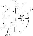
Fig. 9 B is the bottom view of Fig. 9 A.
Fig. 9 C is the top view of Fig. 9 A.
Figure 10 A is the schematic diagram of prior art drill bit, and it has shown the cross section of the workpiece that a drill bit is holed.
Figure 10 B is the bottom view of Figure 10 A.
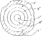
Figure 10 C is the top view of Figure 10 A.
Figure 11 A is the schematic diagram of another prior art drill bit, and it has shown the cross section of the workpiece that a drill bit is holed.
Figure 11 B is the bottom view of Figure 11 A.
Figure 11 C is the top view of Figure 11 A.
The present invention can carry out various improvement and structural change, therefore in describing, accompanying drawing and following details only be described at typical example, therefore be appreciated that this is not limited to disclosed content, on the contrary the variation that the present invention can have various modification and structural change and be equal under the situation of the spirit and scope that violation of a right not requires.
As shown in the figure, when using drill bit in the embodiments of the invention, on workpiece 12, form a circular hole 11 (shown in Fig. 2 and 8), this workpiece is an iron, steel or other metal material, drill bit 10 comprises that the cylindrical body portion of a lengthening is 13, it is made of high-carbon steel in a most preferred embodiment, it has a top 14 and a pair of opposed rod end 15, can certainly adopt the material of other similar physical properties, the rod end 15 of main body 13 is clipped in the power rotary chuck (not shown), thereby drive drill bit 10 around its axis A rotation (Fig. 3 shows), this rotation is as shown in figs. 1 and 3 for being rotated counterclockwise, clearly drill bit also can be held motionlessly, and allows workpiece 12 around the axis A of drill bit 10 rotation.
Usually on main body 13, there are two and radially and longitudinally slot 16 and 17, so that with chip 14 discharges from the top.Groove preferably along 14 extending towards rod end 15 from the top around main body 13 is spiral, is discharged from hole 11 to guarantee metal fragment as depicted in figs. 1 and 2.Groove also can be linear in addition, as shown in Figure 1, the V-arrangement cross section that each groove is normally formed by pair of sidewalls 18 and 19, the sidewall 18 of general groove is towards direction of rotation and sidewall 19 direction of rotation dorsad.
Shown in Figure 1A and 3, fluting 20 radially and 21 adjacent with the head portion of groove 16 and 17 and be formed in the main body 13, and each fluting is close to sidewall 18 1 sides of groove, although in most preferred embodiment of the present invention, fluting 20 and 21 is arranged for spaced radial, but be appreciated that the present invention also comprises some other embodiment, wherein they are to arrange with other equidistant form.Replaceable cutting inserts is placed in this fluting 20 and 21, and when drill bit 10 is rotated counterclockwise the hole 11 of cutting workpiece 12.
Each cutting tip 30,31 is roughly a triangle and has specific bight profile according to the present invention.Clearly, use periphery that triangular blade can guarantee the complete cutting hole 11 of drill bit 10 revolution half-turn blades once.14 places, top of drill bit are strengthened greatly to bear the very big cutting force on the blade 30,31 simultaneously, and the blade of other shape also can use.
Fig. 7 and Fig. 4 have further shown the thin portion of blade 30, clearly be denoted as 30 at this blade 31, blade 30 is an equilateral triangle as shown in the figure, it has three isometric side surfaces 33,34 and 35, they are connected with 38 places in three bights 36,37 each other, these three side surfaces are sandwiched between relative two plane surfaces 40 and 41, the surface 40 and 41 of each blade be formed with a traditional chip groove 42 (Fig. 4 and shown in Figure 6) they just in time to be positioned at the periphery on surface inboard.
Be placed in accurately in receiving slit 20 and 21 owing to each blade 30,31 as shown in Figure 3, the surface 40 of each blade 30,31 is towards direction of rotation and form a cutting face, side surface 34 forms cutting edge 45 with surface 40, and when this cutting edge is from the angle 36 when being extended down to angle 37, it is in that what indicate is straight on the length all almost with 60.When the bight 37, cutting edge 45 begin to be the arc of convex and bend surface 40 the plane and around the bight towards the plane on surface 41.The arch section 47 of cutting edge 45 keeps arc until intersecting (shown in Figure 5) at point 48 places and plane 41.Sword 49 is formed on the plane 41, and this plane is not parallel to face 35.
The shaping of the arch section 47 of cutting edge 45 is surface, limit 35 and the surfaces 40 that connect blade 30,31 by suitable grinding or shaping.Therefore, surperficial 40 bights and surface 35 form a curved surface that is denoted as 50 prominent shape in Fig. 4.
The receiving slit 20 and 21 of blade 30,31 comprises a platform 55 (shown in Figure 1A) respectively, and the surface 41 of blade 30,31 is posted by on this platform.Thereby make groove 20 and 21 be the V character contour at an angle from outwardly directed two sidewalls 56 of this platform and 57 mutual shapes.When blade 30,31 was positioned each groove, surface, limit 33 and 35 abutted in respectively on sidewall 56 and 57, and the summit, bight of each blade is towards the drilling rod end 15 of drill main body 13 like this.
On each blade 30,31 through hole 59 is arranged, it and two surfaces 40,41 vertical (shown in Figure 4) of blade, through hole 59 has a countersunk on two opposites of admitting nut 60 as shown in Figure 5.For the blade in the groove 20,21 30,31 is fixing, bolt or locking pin 60 (Fig. 2,3 shows) must be stretched out from hole 59 and be screwed in the last screw 61 of platform 55 (shown in Figure 1A).
The relative axis A of the platform of each groove tilts, thereby makes the cutting edge 45 of each blade 30,31 be located in a negative axial rake, that is the main cutting face 40 of each blade 30,31 is positioned at the front of cutting edge 45.Therefore, the side surface 34 of blade 30,31 is tilted to forming a clearance plane, thereby avoids in boring procedure the basal surface friction with hole 11, and negative rake is about 7 ° in this example.
Each blade 30,31 also can be fixed like this, be that cutting edge 45 is negative radial rake by dress, that is to say, cutting edge 45 is close proximity to the front of the RADIAL of parallel cutting edge, and the periphery in hole 11 is avoided to avoid and its friction in the bight 36 that is positioned at cutting edge 45 back of each blade 30,31.Wherein, cutting edge 45 is positioned at the RADIAL front approximately greater than the distance of half blade thickness.
The cutting edge 45 of each blade 30,31 can tilt to be about 8 ° lead angle C because such lead angle arranged, when cutting edge when hole wall 11 advances, cutting edge 45 forms a slope towards the drilling rod end 15 of main body 13.Making the core in hole 11 be cut prior to peripheral part slightly and help drill bit 10 like this pierces in the workpiece 12.
By means of aforesaid way, drill bit 10 rotations make the cutting edge 45 of blade 30,31 cut (as shown in Figure 8) in whole pore diameter range.Each cutting edge 45 turns over half periphery in hole 11 when the every rotation half-turn of drill bit 10, and complete periphery of the common cutting of such two blades can guarantee the rapid axial feed of drill bit like this under the situation of only rotating half-turn.
Because the existence of the arch section 47 of cutting edge 45, cutting operation occur in the core in very close hole 11.For fear of the interference between two blades 30,31, the bight 37 of blade 30,31 must be separated from one another, and one of the left side of the bottom in the hole between blade 11 formation roughly becomes columniform core 70 (Fig. 8 shows).
Shown among Fig. 8 that blade 30,31 is roughly a triangle.Two blades orientate its bight 37 as each other very near (that is spacing be 0.15 to 0.5mm), the diameter of core 70 is very little like this.Therefore core 70 can be fractureed easily by the surface, limit 35 in adjacency bight or be broken fully by the top 14 of drill bit when the drill bit axial feed.Because blade the 30, the 31st, leg-of-mutton, when surface, limit 35 by the top 14 of drill bit 10 when drilling rod end 15 advances, the side surface 35 of blade 30,31 is separated from each other apace in the wide-angle X scope at about 44 degree angles.Because there be the metal material use of significant space for drill main body 13 in the separation of side surface 35 broads between them.Therefore, the main part 74 between side surface 35 can be suitable thick, and is being reinforced near 37 places, bight, therefore main body 13 is strengthened.Although the thickness of the part 74 between the side surface of triangular blade 35 is bigger, side surface 35 shrinks towards the top 14 of main body 13, thereby makes bight 37 close each other, thereby has only the core 70 of the frangibility of a minor diameter to stay between the blade.
Each blade 30,31 preferably have interchangeable cutting edge 45 ', it is combined with surface, limit 33 by surface 41 and forms.Cutting edge 45 ' except being used for the location, it is the same with cutting edge 45 in addition, and it also comprises straight line part and an arch section, and is identical with arch section 46 and 47 with the straight line portion of cutting edge 45.Cutting edge 45 ' straight line portion start from bight 36 and the arch section at 38 places of stretching to the angle, cutting edge 45 ' arch section be the curved portions 50 ' (Fig. 7) of an evagination, it is to be positioned on the surface 41 of blade 30,31.
After the cutting edge 45 of blade 30,31 is worn, blade can be taken out from groove 20,21.With upset of two blades and transposition, to cutting position, each blade has just had two cutting edges that are used alternatingly like this with cutting edge 45 ' change, and this blade is just scrapped after two cutting edges all are worn.
As if the geometry that can know these drill bit tops and blade from prior art is the U.S. Patent No. 5 of Shallenberger, 092, geometry described in detail is such in 718, the groove that wherein holds blade is that mutual diametrically contraposition is arranged, and blade stretches into workpiece with approximately being equal to.
Geometry of the present invention needs accurate balance, and wherein, the geometry at drill bit top is the ten minutes balance, and, the active length (see figure 1) of drill bit, that is the part that drill bit can stretch in the boring is longer than the indexable drill of prior art.We find, blade 30,31 is accurate opposed mutually and by stretching out in the groove, thereby accurately are equal to workpiece 12 and contact, and this will produce the stock removal rate of a balance at the cutting top, thereby the deflection of drill bit does not take place, distortion or fracture.
The method of this enforcement will be understood better by representing Fig. 9 A-C of the present invention and Figure 10 A-C of expression prior art and the drill bit of 11A-C.At first present invention is described with reference to Fig. 9 A-C, the every rotation half-turn of drill bit of the present invention, and hole 11 is by one week of complete cutting " a ".When drill bit 13 was pushed ahead by workpiece 12, radial load E acted on the blade 30, and radial load F acts on the blade 31 simultaneously.Because blade 30,31 accurately is equal to leading thread to opposed, power E that is produced and F are identical and cancel out each other.
The importance of balance is preferably understood by comparing with the prior art drill bit shown in Figure 10 A-C and Figure 11 A-C.At first can see when drill main body 13 ' by workpiece 12 ' when pushing ahead from Figure 10 A-C, radial load E ' act on blade 30 ' on, simultaneously radial load F ' act on blade 31 ' on.From Figure 10 C, can also see complete cutting hole 11 ' drill bit of periphery need rotate a whole circle, blade a 30 ' a ' of cutting circle wherein, while blade a 31 ' b ' of cutting circle.They just can not cancel each other out and be superimposed because power E ', F ' action direction are identical, make drill bit depart from the rotation of strictness.This deflection will be enough to cause blade 30 ' edge 100 and hole 11 ' inwall rub mutually.The drill bit that therefore this deflection will limit prior art has low relatively draw ratio (Figure 10 A-C shows), because when this deflection is arrived to a certain degree greatly, the engagement friction will be greater than the rotary power of power source, and perhaps will cause the burn in hole or scab, or with main body 13 ' fracture.
Similarly, the drill bit shown in Figure 11 A-C comprises two blades, and they also must rotate a circle and come complete cutting hole 11 " periphery once.Shown in Figure 11 A and 11B, blade 30 " comprise cutting face 101 and 102, and blade 31 " comprises cutting face 103 and 104.Referring now to the profile in the hole shown in Figure 11 C, can see that cutting face 101 the has produced a circumference cutting of " circumference cutting, and cutting face 102 has produced b ", c has been cut on surface 103 ", d has been cut on surface 104 ".When drill main body 13 " by workpiece 12 " axial advance, radial load E " acts on the surface 101; radial load E2 acts on the surface 102; radial load F " acts on the surface 103, radial load F2 acts on the surface 104, yet since the surface 101 the cutting peripheral band a " area be greater than the surface 102 the cutting circumference band b ", therefore " and F2 can not offset power E each other; " and F2's same power F can not cancel out each other, therefore drill bit will deflect and cause blade 30 like this " side 105 rub with the inner surface in hole 11 and contact, this must limit the draw ratio of obtainable drill bit.
Therefore, two blades are placed in very accurate balance opposed locations according to the present invention, this will balance the radial load that acts on the blade basically, in addition, because each blade contacts accurately with workpiece in an identical manner, therefore, each blade is done identical work, thereby cutting force equates, draw ratio of the present invention so just can not resemble in the prior art be restricted in 3: 1, and can be 4: 1 or higher, what in fact experiment was successful accomplished 10: 1.
Know expression as Fig. 1, the active length L of drill bit is from far away greater than the diameter on top 14.In the embodiment shown in fig. 1, length L is represented as 6 times of diameter D, although all design draw ratios of the present invention are all greater than 4: 1.Before the present invention, this draw ratio is considered to impossible, and this is that the aforesaid radial load that is produced will cause due to the deflection because the cutting face contacts with workpiece.
Yet cutting tip 30 provided by the present invention and 31, their accurate balances are mutually cancelled out each other capable E and F, thereby the length L that had of main body 13 is greater than 4 times of diameter D.
Therefore, the active length L of drill main body 13 of the present invention can be much larger than the top 14 diameter.In fact experiment success has finished draw ratio L/D up to 10: 1.This must will cause hole 11 to have with respect to the diameter that provides equally becomes possibility than bigger length mentioned above.
As previously mentioned, the invention provides a kind of new and improved drill bit 10, the length L of its main body 13 is greater than 4 times of diameter D at top 14 at least.Because used the indexable insert tip, throw away tip 30 and 31 of multiple-cutting-edge, a complete circumference drill bit of their cutting holes 11 only need rotate half cycle, so drill bit can the faster rate axial feed.Because blade is leg-of-mutton, the bight 31 that blade is adjacent can be arranged to very close mutually, and the thicker position of drill main body 13 can be between blade near the position at angle 37, thereby have at drill bit under the situation of higher draw ratio and also can be strengthened, the more important thing is owing to act on radial load E on blade 30 and 31 and F, so main body 13 can keep aforesaid draw ratio and the deflection of drill bit not take place by balance exactly.

Claims (8)

1、一种钻头,它包括一个加长的大致圆柱形的具有预定轴线的主体,该主体具有一个杆端部分,一个具有一个外周边的顶端部分,以及一个轴向工作长度L,该长度为在钻孔时所说的钻头可以伸入孔中的长度,形成在所说的主体的顶端的第一和第二沟槽,它们位于轴线两侧直径上相对的位置,第一和第二刀片分别位于所说的第一和第二沟槽内,可拆卸地固定于所说的主体上,每个刀片具有由至少三个侧面所界定的大致扁平且平行的两个表面,每个所述刀片的至少一个侧面具有一切削刃,它横向延伸靠近顶端的主体,从位于外周边向外的第一角部至位于不到所说轴线的第二角部,第一和第二刀片的第一角部之间的距离为钻头的直径D,钻头主体的工作长度L至少为直径的4倍。1. A drill bit comprising an elongated substantially cylindrical main body with a predetermined axis, the main body having a shank end portion, a tip portion having an outer periphery, and an axial working length L, the length being in When drilling, said drill bit can extend into the length of the hole, forming the first and second grooves on the top of said main body, which are located at opposite positions on both sides of the axis diameter, and the first and second blades are respectively Located in said first and second grooves, detachably fixed on said body, each blade has two substantially flat and parallel surfaces defined by at least three sides, each of said blades At least one side of the at least one side has a cutting edge, and it extends laterally near the main body of tip, from the first corner that is located outside the outer periphery to the second corner that is located less than said axis, the first and second blades The distance between the corners is the diameter D of the drill bit and the working length L of the drill body is at least 4 times the diameter. 2、根据权利要求1的钻头,其特征在于,所说的主体的工作长度至少为直径的10倍。2. Drill bit according to claim 1, characterized in that the working length of said main body is at least 10 times the diameter. 3、根据权利要求1的钻头,其特征在于,切削刃从每个所说的第一角部至所说的第二角部为一个直线,然后成弧形,当靠近第二角部时由第一面的平面凸起并朝向所说的第二面的平面。3. The drill bit of claim 1, wherein the cutting edge is a straight line from each of said first corners to said second corner, and then arcuately formed by The plane of the first side is convex and faces the plane of said second side. 4、根据权利要求3所述的钻头,其特征在于,所说的切削刃的弧形部分与所说的第二面的平面相接。4. The drill bit of claim 3 wherein the arcuate portion of said cutting edge meets the plane of said second face. 5、一种钻头,它包括一个加长的大致圆柱形的具有预定轴线的主体,并且它可以按预定的方向绕其轴线旋转,该主体具有一个顶端部分和一个相对的杆端部分,顶端部分具有一个外周边;5. A drill bit comprising an elongated generally cylindrical main body having a predetermined axis and which is rotatable about its axis in a predetermined direction, the main body having a tip portion and an opposite shank end portion, the tip portion having an outer perimeter; 在主体上大致径向上相对的位置具有第一和第二沟槽,它们从顶端朝向杆端延伸,它们的径向横截面大致为V形,它们由一对侧壁构成,该第一和第二沟槽其预定长度至少为L;There are first and second grooves at substantially radially opposite positions on the main body, they extend from the top end toward the rod end, their radial cross-section is roughly V-shaped, and they are formed by a pair of side walls, the first and second grooves The predetermined length of the second groove is at least L; 在主体的顶端位部径向对置设有第一和第二槽,该第一个槽与前述的第一沟槽的一个侧壁相邻接,第二槽与前面所说的第二沟槽的相应壁相邻接,每个槽大致成V形,它们由朝向杆的旋转方向的平面和一对从该平面延伸的侧面构成,每个槽的V形顶点指向主体的杆端部分;The first and second grooves are arranged radially opposite to each other at the top portion of the main body, the first groove is adjacent to a side wall of the aforementioned first groove, and the second groove is adjacent to the aforementioned second groove. corresponding walls of the slots abut, each slot being generally V-shaped, they are formed by a plane facing the direction of rotation of the rod and a pair of sides extending from that plane, the apex of each slot pointing towards the rod end portion of the body; 第一、第二切削刀片分别被设置在第一、第二槽中,并且,可拆卸地固定在主体上,两刀片径向相对地配置,从而当钻旋转和轴向进给时,作用在每个刀片上的径向力在顶端的一预定轴线上相互平衡掉,因而避免了顶端的偏转,每个刀片大致为三角形,并且具有一个与接收槽的平台相接靠的表面,另外相对的一个表面朝向主体的旋转方向并形成一个切削面,每个切削刀片还具有三个大致等长的切刃表面,并且,它们位于前述的两表面之间,三个切削表面在其连接处形成三个角部,三个表面中的两个表面位于贴靠于相应的槽的侧壁上,另一个表面朝向钻杆横向邻接其顶点处伸展,刀片第三表面与切削表面形成一个切削刃,每个切削刃沿主体横向伸展,从朝向外圆周的刀具的第一角部伸向未达到轴线的第二角部,各刀片的第一角部之间的距离为钻头的钻削直径D,每个切削刃具有一个直线部分和一个弧形部分,直线部分是从第一角部到第二角部之间,弧形部分是从直线段开始绕过第二角部朝向相应的平台,每个刀片上均作用有径向力,因此当钻头通过工件轴向进给时,由于刀片的精确的定位,每个刀片所受的径向力相等因而彼此被平衡抵消掉,钻头的工作长度L可以至少为钻削直径D的4倍。The first and second cutting blades are respectively arranged in the first and second grooves, and are detachably fixed on the main body. The two blades are arranged radially opposite to each other, so that when the drill rotates and feeds axially, it acts on the The radial forces on each blade are mutually balanced on a predetermined axis of the tip, thereby avoiding deflection of the tip, each blade is roughly triangular in shape, and has a surface that abuts against the platform of the receiving groove, and an opposite One surface faces the direction of rotation of the main body and forms a cutting face, and each cutting insert also has three cutting edge surfaces of approximately equal length, and they are located between the aforementioned two surfaces, and the three cutting surfaces form three cutting surfaces at their junction. two corners, two of the three surfaces are located against the side walls of the corresponding grooves, and the other surface extends toward the drill rod laterally adjacent to its apex, and the third surface of the blade forms a cutting edge with the cutting surface, each Two cutting edges extend laterally along the main body, from the first corner of the tool facing the outer circumference to the second corner not reaching the axis, the distance between the first corners of each blade is the drilling diameter D of the drill bit, each Each cutting edge has a straight portion and an arc portion, the straight portion is from the first corner to the second corner, and the arc portion is from the straight portion around the second corner toward the corresponding platform, each There is a radial force acting on the blades, so when the drill bit is fed axially through the workpiece, due to the precise positioning of the blades, the radial forces on each blade are equal and thus offset each other, and the working length L of the drill bit can be At least 4 times the drilling diameter D. 6、根据权利要求5所述的钻头,其特征在于,钻头的工作长度L至少为钻削直径D的10倍。6. Drill according to claim 5, characterized in that the working length L of the drill is at least 10 times the drilling diameter D. 7、根据权利要求5所述的钻头,其特征在于,每个刀片的切削面基本上是平的,但是朝向平台靠近第二角部处稍微凸起,从而在切削刃上形成了一个弧形的切削刃部分。7. The drill bit of claim 5, wherein the cutting face of each insert is substantially flat, but slightly convex toward the land near the second corner, thereby forming an arc on the cutting edge cutting edge part. 8、根据权利要求5所述的钻头,其特征在于,每个刀片包括一个第三角部,从第一角部到第三角部之间形成一个备用的切削刃,它是位于第一表面和一个侧表面的结合线上,该备用切削刃具有一个从第一角部延伸的直线段部分和靠近第三角部的一个外凸的弧形部分。8. The drill bit of claim 5, wherein each insert includes a third corner, and a spare cutting edge is formed between the first corner and the third corner, which is located between the first surface and a On the joining line of the side surfaces, the spare cutting edge has a straight line portion extending from the first corner and an outwardly convex arc portion adjacent the third corner.
CN97122562A 1996-11-06 1997-10-09 Elongated drill with replaceable cutting inserts Expired - Fee Related CN1069248C (en)

Applications Claiming Priority (2)

Application Number Priority Date Filing Date Title
US746,033 1996-11-06
US08/746,033 US5816754A (en) 1996-11-06 1996-11-06 Elongated drill with replaceable cutting inserts

Publications (2)

Publication Number Publication Date
CN1184012A CN1184012A (en) 1998-06-10
CN1069248C true CN1069248C (en) 2001-08-08

Family

ID=24999219

Family Applications (1)

Application Number Title Priority Date Filing Date
CN97122562A Expired - Fee Related CN1069248C (en) 1996-11-06 1997-10-09 Elongated drill with replaceable cutting inserts

Country Status (7)

Country Link
US (1) US5816754A (en)
EP (1) EP0841115A1 (en)
JP (1) JPH10296514A (en)
KR (1) KR100243848B1 (en)
CN (1) CN1069248C (en)
CA (1) CA2213544C (en)
IL (1) IL121935A (en)

Cited By (1)

* Cited by examiner, † Cited by third party
Publication number Priority date Publication date Assignee Title
CN102574211A (en) * 2009-10-28 2012-07-11 钴碳化钨硬质合金公司 Multi-Indexable Cutting Inserts for Drilling Tools

Families Citing this family (24)

* Cited by examiner, † Cited by third party
Publication number Priority date Publication date Assignee Title
US6000887A (en) * 1998-05-19 1999-12-14 Ingersoll Cutting Tool Company Stiff drill
US6238151B1 (en) * 1998-09-28 2001-05-29 Mitsubishi Materials Corporation Drilling tool and throw-away tip for use in drilling work
SE519575C2 (en) * 2000-04-11 2003-03-18 Sandvik Ab Metal-cutting drill has a tip formed of cutting edges of a specific geometry designed to optimise metal cutting speed
US6874979B2 (en) * 2001-07-05 2005-04-05 Mitsubishi Materials Corporation Throw-away tip for use in drilling work and throw-away drilling tool
US6808340B2 (en) 2002-09-06 2004-10-26 Prototype Productions, Inc. Tool apparatus
CA2498197C (en) * 2002-09-09 2011-02-01 Komet Group Holding Gmbh Drilling tool with interchangeable inserts, and interchangeable inserts for said drilling tool
US20050163921A1 (en) * 2004-01-23 2005-07-28 The Boeing Company Method of repairing a workpiece
DE102004058163A1 (en) * 2004-12-02 2006-06-08 Kennametal Inc. Drilling / chamfering tool
US9079260B2 (en) * 2007-11-01 2015-07-14 GM Global Technology Operations LLC Polycrystalline diamond cutting tool with coated body
JP2009226560A (en) * 2008-03-25 2009-10-08 Yunitakku Kk Gun drill
JP2009241239A (en) * 2008-03-31 2009-10-22 Fuji Seiko Ltd Drill and boring machining method
CN102489730B (en) * 2011-11-25 2013-06-12 天津市瑞德螺杆泵制造技术有限公司 Tool for carrying out numerical control machining on spiral profiles of screws of twin-screw pump
CN103506666B (en) * 2012-06-20 2017-10-03 博世电动工具(中国)有限公司 Blade for drill bit
WO2014015154A1 (en) 2012-07-18 2014-01-23 Milwaukee Electric Tool Corporation Hole saw
EP3175943B1 (en) * 2014-07-29 2024-08-28 KYOCERA Corporation Drill and method of manufacturing cut product using same
CN104827094A (en) * 2015-05-26 2015-08-12 苏州阿诺精密切削技术股份有限公司 V-shaped positioning double-screw locking tooth crown drill bit
CN104907614A (en) * 2015-05-26 2015-09-16 苏州阿诺精密切削技术股份有限公司 V-shaped locating double-screw locking crown drill rod
JP2017094467A (en) * 2015-11-26 2017-06-01 住友電工ハードメタル株式会社 Rotating tool
DE102018114139A1 (en) * 2018-06-13 2019-12-19 Botek Präzisionsbohrtechnik Gmbh Deep hole drill and drilling tool with one or more recesses in the rake face
CN216028284U (en) 2018-07-10 2022-03-15 米沃奇电动工具公司 Hole saw
CN109623008A (en) * 2018-12-12 2019-04-16 中色科技股份有限公司 A kind of processing unit (plant) and method of deep hole end face
DE102019100891A1 (en) 2019-01-15 2020-07-16 Botek Präzisionsbohrtechnik Gmbh Drill head for milling out non-cylindrical inner contours
EP3986650A4 (en) 2019-06-20 2023-07-19 Milwaukee Electric Tool Corporation Hole saw with circular sidewall openings
USD958855S1 (en) 2019-12-09 2022-07-26 Milwaukee Electric Tool Corporation Hole saw

Family Cites Families (13)

* Cited by examiner, † Cited by third party
Publication number Priority date Publication date Assignee Title
USRE26452E (en) * 1964-10-20 1968-09-10 Gun drill
SU521074A1 (en) * 1974-07-17 1976-07-15 Предприятие П/Я В-8772 Spiral drill
US3963365A (en) * 1975-05-07 1976-06-15 Metal Cutting Tools, Inc. Drill with indexable inserts
US4373839A (en) * 1979-10-02 1983-02-15 Mitsubishi Kinzoku Kabushiki Kaisha Drill bit
DE8536123U1 (en) * 1985-12-21 1987-04-16 Komet Stahlhalter- Und Werkzeugfabrik Robert Breuning Gmbh, 7122 Besigheim Drilling tool
DE3601385A1 (en) * 1986-01-18 1987-07-23 Krupp Gmbh METHOD FOR PRODUCING SINTER BODIES WITH INNER CHANNELS, EXTRACTION TOOL FOR IMPLEMENTING THE METHOD, AND DRILLING TOOL
JPH03501583A (en) * 1988-09-29 1991-04-11 ベロルススキ ポリテクニチェスキ インスチテュート deep hole drilling drill
US5174691A (en) * 1989-09-05 1992-12-29 Ford Motor Company High feed rate deep penetration drill
US5092718A (en) * 1990-12-10 1992-03-03 Metal Cutting Tools Corp. Drill with replaceable cutting inserts
DE4117486C2 (en) * 1991-05-28 1995-07-27 Hitachi Seiko Kk drill
DE4204428C2 (en) * 1992-02-14 1994-02-03 Dornier Luftfahrt Hollow drilling tool for the production of cylindrical bores
DE9312802U1 (en) * 1993-08-26 1993-11-25 Werthwein, Gustav, 71665 Vaihingen Drilling tool
DE4416040A1 (en) * 1994-05-03 1995-11-09 Johne & Co Praezisionswerkzeug Drilling tool

Cited By (3)

* Cited by examiner, † Cited by third party
Publication number Priority date Publication date Assignee Title
CN102574211A (en) * 2009-10-28 2012-07-11 钴碳化钨硬质合金公司 Multi-Indexable Cutting Inserts for Drilling Tools
CN102574211B (en) * 2009-10-28 2015-02-18 钴碳化钨硬质合金公司 Multi-Indexable Cutting Inserts for Drilling Tools
CN104588740A (en) * 2009-10-28 2015-05-06 钴碳化钨硬质合金公司 multiplex exchangeable cutting plate for a drilling tool

Also Published As

Publication number Publication date
JPH10296514A (en) 1998-11-10
CA2213544C (en) 2000-11-07
US5816754A (en) 1998-10-06
KR100243848B1 (en) 2000-03-02
CN1184012A (en) 1998-06-10
IL121935A0 (en) 1998-03-10
EP0841115A1 (en) 1998-05-13
IL121935A (en) 2001-01-11
KR19980042014A (en) 1998-08-17
CA2213544A1 (en) 1998-05-06

Similar Documents

Publication Publication Date Title
CN1069248C (en) Elongated drill with replaceable cutting inserts
CN1046885C (en) A chip cutting tool
CN1186156C (en) Cutter for drilling and shaving groove
CN1319692C (en) Multi-edge inserts and multi-edge insert cutting tools
CN1206074C (en) Rotatable tool having replaceable tip at chip removing free end of tool
EP0814932B1 (en) Helical cutting insert with offset cutting edges
CN1239910A (en) Cutting tool assemblies and cutting insert inserts thereof
CN1950166A (en) Drill and drill tip for chip removing machining
CN1228044A (en) Insert blade
CN101663121A (en) Cutting insert
CN1747807A (en) Rotatable cutters and cutting inserts for chip removal
CN101998890A (en) Tool body of tool for plunge milling, tool for plunge milling, and method for plunge milling
CN110366467A (en) Combined countersink drill
CN1689740A (en) Rotatable tool for chip removal
CN1024768C (en) Cutting insert for milling cutting tool
CN1535194A (en) Knives with inserts mounted on their edges
CN1179812C (en) Indexable drill bit and its cutting insert
CN1179122A (en) Helical cutting inserts with compensating cutting edges
WO2020230569A1 (en) Boring holder and turning tool
CN2229320Y (en) The screwing structure of the drill bit and the design and arrangement of the tool angle
CN1468679A (en) Inserts for drills and drilling tools using such inserts
CN205733143U (en) A kind of three traverse drill reaming step drill
WO2022065510A1 (en) Cutting insert, rotary tool, and method for manufacturing cut product
JP2649015B2 (en) Drill
JP4725369B2 (en) Drill

Legal Events

Date Code Title Description
C06 Publication
PB01 Publication
C10 Entry into substantive examination
SE01 Entry into force of request for substantive examination
C14 Grant of patent or utility model
GR01 Patent grant
C19 Lapse of patent right due to non-payment of the annual fee
CF01 Termination of patent right due to non-payment of annual fee