Therefore, the objective of the invention is to create one and overlap the machining center of the sort of type of mentioning at first, it can make the removal of the metal fillings of shorter workpiece process time and simplification become possibility when reducing manufacturing expense.
For the design that achieves this end is, work supporting block is incorporated on the clamping plate that are provided with clamping device, wherein work supporting block is installed on the positioner in replaceable mode together with clamping device, and be provided for the replacing station of work supporting block, positioner receives the work supporting block that process operation needs from feedway there.
In such a way, clamping device has dual-use function, because it both had been used for workpiece manipulation and has transported and transport machining area, also is used for holding workpiece during processing in addition.In order to make the machining center rapid tool change, to handle other workpiece, work supporting block is installed on the positioner in replaceable mode.Work supporting block just can be replaced together with the clamping device above it like this, work supporting block by the clamping device of a different structure is replaced, the replacing of clamping device is to change in the station at workpiece to carry out, and wherein positioner receives the work supporting block that process operation needs from feedway.
Although press under the situation of lathe among the European patent publication 0088645A1 as vertical lathe use, want each processed workpiece from the warehouse, to be taken out by chuck, again put back in completion of processing, still, this application is limited in having in the rotary manipulation of rotation chuck and setting tool.Under the situation that the machining center as the sort of type of mentioning at first uses, get back to again with additional gripper and come travelling workpiece.
Same problem also is suitable for the disclosed lathe at German patent publication thing 4022458A1.Here, the work supporting block that rotates during use be placed in static machining tool below, under the help of gripper, supply with workpiece.Although this supply required time is than short under the above-mentioned European patent publication 0088645A1 situation, owing to used two grippers, desired for this reason higher mechanical technique causes the tangible raising of this machining tool cost.
And German patent publication thing 3416660A1 proposed a kind of suggestion, is used for picking up workpiece from the workpiece warehouse in a clamp operation, processes them and returns them.Yet this only is again the problem of lathe, and this lathe uses the chuck that links to each other with operation axis to catch workpiece.Also have, in this lathe, replacing does not have possibility clamping device, the necessary work supporting block of machining center usually.
Further scheme of the present invention will be:
Change in the station at the take workpiece of workpiece to be processed of working tray, workpiece prepares that the position can to store the position identical with workpiece.
In order to obtain best metal fillings removal effect, below machining area, adorn a metal fillings receive path from practical standpoint, lead to conveyer, the metal fillings that produces is transported.
A processing unit (plant) is set at least can be designed as single main shaft or many main shaft forms of implementation.Single main shaft design especially is applied to High-speed machining, at this moment can only preferentially select a kind of like this solution for use, is main shaft and motor combination a unit promptly.Particularly in single main axle structure pattern, preferably design several especially two such processing unit (plant)s simultaneously, these processing unit (plant)s preferably are installed in the horizontal plane side by side, and work independently of one another.Like this, can carry out process operation such as a processing unit (plant), and, can carry out tool changing as for present obsolete processing unit (plant).
Replacing instrument is for convenience preferably equipped a suggestion with the changing device of work supporting block-more and join a work supporting block warehouse.Between changing device of work supporting block-more and work supporting block warehouse, change working tray, can be such as carrying out with hand or with suitable auxiliary equipment.
A preferred embodiment of the present invention is stipulated like this: work supporting block is arranged at the cantilever shape part of positioner, so that provide space as much as possible for work supporting block mobile.
To explain this invention in detail by means of accompanying drawing below.
All figure take the sketch form.Special necessary driving and the control device of expression of also having abandoned, such driving and control device are known, can be packed into by the professional as required.
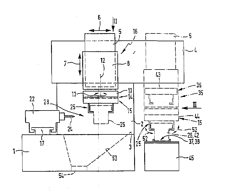
Machining center shown in Fig. 1 to 5 comprises a workbench or support 1, and a upwardly extending pillar 2 is arranged at the back side of workbench.At the upside of pillar, with upper surface 3 certain vertical distance of support first horizontal guide rail 4 is arranged, be the rail shape such as it.A vertical guide rail 5 is installed on the horizontal guide rail 4, makes horizontal rectilinear motion, and first horizontal movement direction is shown in double-head arrow 6 accordingly.
On vertical guide rail 5, having installed one can be by the mobile lifting slide unit 8 of drive along the vertical moving direction shown in the double-head arrow 7.
In the bottom of lifting slide unit 8, a rotating disk 11 is arranged.It can rotate around vertical axis 8 with respect to lifting slide unit 8.Rotation direction is by shown in the double-head arrow 13.
In the bottom of rotating disk 11,, fix a work supporting block 15 in removable mode by jockey 14.Rotating disk 11, lifting slide unit 8, vertical guide rail 5 and first horizontal guide rail 4 form one and are referred to as 16 positioners, and positioner is to establish for the work supporting block 15 that is attached thereto.Therefore, work supporting block can move along direction 6,7 and 13 as required, so that enter desirable position.
Second horizontal guide rail 17 is positioned at the scope of upper surface 3 of the support of support 1.Shown in perpendicular plan view, this horizontal guide rail and first horizontal guide rail 4 direction that meets at right angles.This horizontal guide rail is equipped with a processing unit (plant) 22, and processing unit (plant) 22 can move back and forth in second horizontal movement direction along the rail length direction shown in double-head arrow 18.In this example, relate to single main shaft processing unit (plant), it has a machining spindle 23, and desirable machining tool 24 is installed on the machining spindle 23 in removable mode.By one with processing unit (plant) 22 one, unillustrated drive motors, can drive machining spindle 23 with form known, thereby drive machining tool 24, realize rotatablely moving.Under present situation, the design of motor allows High-speed machining.
On the position of single main shaft processing unit (plant) 22, also can be with many main shaft processing unit (plant)s, it can match with a plurality of process tools that are driven in rotation simultaneously.
Work supporting block 15 is equipped with a clamping device 25, so that the workpiece 26 that will process can be clamped and fixed in the pre-position of work supporting block 15 releasedly.This position is known as bracket locations.6,7,13 and 14 one-movement-freedom-degree above-mentioned makes and machining tool 24 and relatively moving make that the latter can be processed arbitrarily by making process tool 24 enter clamped condition by desired mode and workpiece between the workpiece 26 of bracket locations.
Vertical guide rail 5 and lifting slide unit 8 are contained in the front of first horizontal guide rail 4, and the result is that the rotating disk 11 of lifting slide unit 8 and specially installation is given prominence to (Fig. 3) forward with cantilevered fashion.This means work supporting block 15,, be fixed on top and a distance, carriage 2 front of the upper surface 3 of support with the workpiece 26 that is positioned at bracket locations.Positive 27 are the parts that are being positioned at above the support 1, are being known as machining area 28, therefore can get at without restriction usually and also see clearly Chu.
According to this example, take such frame mode, promptly first horizontal movement direction 6 is along the width of support 1, thus the direction of pressing among Fig. 2 is from left to right extended.Depth direction along support 1 between second horizontal movement direction 18 front and back extends.In this example, second horizontal guide rail 17 is placed in the left hand marginal portion of support 1, and the rotating shaft 32 of machining spindle 23 is parallel to first horizontal movement direction 6 and extends.Shown in the vertical view among Fig. 2, machining area 28 is by first and second horizontal guide rail 4 and 17, and the front side of support 1 and right edge 33 and 34 surround.
Positioner 16 not only is used for locating workpiece 26 in process, and changes the position of the work supporting block of being loaded onto 15 in the above between machining area 28 that is used for mentioning and the workpiece replacing station 35.Workpiece is changed station 35 and is preferably in outside the machining area 28, and according to bowing shown in the diagrammatic sketch of Fig. 2, in this embodiment of this invention, workpiece is changed the next door that station 35 is positioned at right edge 34.Change in the station 35 at workpiece, may carry out the workpiece replacing relevant, that is to say that the workpiece that is positioned in advance on the bracket locations is replaced by workpiece and then to be processed after processing with work supporting block 15.The replacement of a workpiece appears here.
First horizontal guide rail 4 one sides extend beyond right edge 34, make vertical guide rail 5 energy and work supporting block 15 together, move to workpiece along this first horizontal guide rail 4 and change in the station 35.Be arranged in workpiece and change the workpiece replacing place at station 35 in 36 expressions of Fig. 1 and 2 with dashed lines.
Change in the position 36 at workpiece, work supporting block 15 occupies at workpiece and changes the position that workpiece is prepared position 37 vertical direction in the station 35.For workpiece 26 being provided for empty work supporting block 15, corresponding workpiece 26 is arranged at the preparation position 42 that workpiece is prepared 37 next doors, position.And then, the work supporting block 15 that is positioned at workpiece replacing position 36 moves down along vertical motion direction 7 and enters receiving position 44 from being positioned at the preparation position 43 of workpiece 26 top certain distances; Catch workpiece and clamp it with its clamping device 25 at the receiving position work supporting block.Clamping device 25 is from top direct reception workpiece 26, so clamping device is carried out the gripper function simultaneously.In this position, clamping device 25 is accepted workpiece 26 from preparing position 42, and workpiece 26 is sandwiched on the work supporting block 15 always, and after machining, it is taken back to workpiece and changes in the station 35.Mention from workpiece preparation position 37 at the lifting slide unit 8 that preparation position 42 clamped workpiece 26 are vertically risen, after this on work supporting block 15, be in hanging position, change station 35 up to being returned workpiece.
This returning with opposite sequence of motion carried out, and work supporting block 15 at first is brought to workpiece and changes station 36, makes it be positioned at above the workpiece stored position 38 of workpiece switching station and has the high position of certain distance to prepare position 43.This workpiece stored position 38 is preferably prepared position 37 with workpiece and is overlapped, and makes to be put back to the position of preparing position 42 corresponding to the front by reducing by 15 ° of workpiece that process of work supporting block.
Obviously, there is no need must to prepare position 37 identical with workpiece for workpiece stored position 38.At first under the situation that workpiece 26 is provided continuously,, be worth the other workpiece stored position 38 of suggestion selection if workpiece preparation position 37 can not continue to keep idle the process of the workpiece of getting fortune from it there especially.Workpiece stored position 38 is preferably in the next door that workpiece is prepared position 37, perhaps, but wants first horizontal guide rail 4 corresponding prolongations, and the workpiece stored position is located in the scope on limit, left side 45 of support 1.From being clear that here, it must be a construction unit that workpiece replacing station 35 there is no need, and can thoroughly be divided into some parts part separated from one another.A part, such as accepting workpiece, this can be known as " picking " function, and in another part, returns processed intact workpiece.
The workpiece 26 shift-in workpiece that will process are prepared position 37, be preferably under the help of Work conveying apparatus 45 and carry out, in example shown in present Fig. 1 to 5 of this invention, Work conveying apparatus is designed to the form of conveyer belt, and it passes, and workpiece is changed station 35 and machining center moves near right edge 34 1 sides.Can arrange a plurality of machining centers one by one along depth direction, make conveyer belt through all machining centers, the workpiece that process is according to separately folder situation, and quilt machining center is separately taken away.In this case, in fact Work conveying apparatus 45 represents a workpiece warehouse cheaply, and it makes the workpiece supporting plate of the costliness do not need to be equipped with clamping device.
Under the situation of embodiment shown in Figure 6, the Work conveying apparatus 45 ' that adopts garden console form is provided, workpiece 26 can be placed on the rotating disk that passes workpiece replacing station 35 successively.
Change in the station 35 at workpiece, receive workpiece 26 reliably, preferably make to be positioned at the workpiece 26 that workpiece is prepared position 37, prepare to align in advance by using positioner 46 in order to guarantee work supporting block 15.In this respect, may relate to location or steady pin, it sets the alignment of the certain angle of workpiece 26.If workpiece 26 is provided by Work conveying apparatus 45 and 45 ',, corresponding positioner 46 is all arranged at each location of workpiece 49 place from practical standpoint.
Under the situation of preferred embodiment, work supporting block 15 comprises a base plate, is also referred to as the chuck plate, and its upside is fixedly connected on the rotating disk 11, and base plate plane is to extend with the vertical axes 12 rectangular directions of rotation.At link position, on the base plate face 48 down clamping device 25 is arranged.Work supporting block 15 is changed in the station 36 at workpiece and is also got this position, and making moves both vertically is enough to accept workpiece 26, and clamping device 25 is placed on from above on the workpiece 26 that is positioned workpiece preparation position 37.Clamping device 25 self can be complementary such as the hydraulic pressure clamping device in a usual manner with suitable, and the clamping connection and the composition surface that to require, makes in the automatic operating process of the work in-process heart, can realize catching and clamping of workpiece 26.The clamping that requires and catch motion in Fig. 1, to represent by double-head arrow 52.
Because workpiece 26 is in the machining area processing that is draped, so most metal fillings 15 that produce, replace another work supporting block 15 ' and be connected, so this new work supporting block 15 ' occupies the Working position 61 that has been illustrated by Fig. 1 to 5 with the positioner 16 of zero load.Work supporting block more changing device 58 is also preferably born moving of work supporting block 15 and 15 ' turnover work supporting block warehouse 57 at least in part.
In the present embodiment, work supporting block more changing device 58 is arranged in the scope of support 1 right edge 34.It has a chuck 62, and chuck is above horizontal guide rail 63, and 63 are contained on the guide rail 64 of horizontal linearity extension, and chuck can be parallel to second horizontal movement direction 18 and move according to direction shown in the double-head arrow 65.Guide rail 64 preferably is installed on the support 1.Two " loaded " position 66 and 67 are arranged on chuck 62, and they are applicable to respectively with manner and accept or fixation workpiece carriage 15 and 15 '.Chuck 62 described in this embodiment is designed to be similar to fork-shaped, has two grooves that constitute " loaded " position 66 and 67 side by side, and their openings are towards the front of chuck.For at " loaded " position 66 and 67 fixation workpiece carriages, above-mentioned work supporting block 15 is injected the corresponding " loaded " position 67, shown in arrow 72 from the front of opening.The work supporting block that taking-up is fixed is to extract out from corresponding " loaded " position 67 by pressing the rightabout shown in the arrow 73.The direction 72 and 73 that injects and extract out is parallel to the horizontal movement direction 65 of chuck 62.
Chuck 62 is to arrange like this, promptly loads the rear side of the open front face of position 66 and 67 towards support.Work supporting block is changed and is carried out as described below:
A " loaded " position 66 keeps unloaded, and another " loaded " position 67 is equipped with new work supporting block 15 '.Loading occurs in home position 71, and wherein horizontal guide rail 63 is arranged in the positive scope of support, as shown in Figure 4.Be positioned at the work supporting block 15 of Working position 61 now, fix like this by positioner 61, promptly it is directly relative with unloaded " loaded " position 66 in the horizontal direction.This centre position as shown in Figure 5.Next step is that horizontal guide rail 63 moves in the direction of work supporting block 15 along arrow 74, so work supporting block 15 enters unloaded " loaded " position 66.This centre position is shown in dotted line among Fig. 5 75.The new work supporting block that is fixed on second " loaded " position 67 is other at work supporting block to be removed 15, is positioned at horizontal movement direction 6.
Jockey 14 is unlocked now, and rotating disk 11 moves in new work supporting block direction along horizontal movement direction 6, and keeps the height of oneself, and is positioned at the work supporting block 15 of Working position 61 always, has stayed first " loaded " position 66.In this lateral movement process, engage gradually with being connected of the work supporting block 15 in past and to remove, with being connected to engage and beginning to form of new work supporting block 15 ', arrive Working position 61 simultaneously up to new work supporting block.At this moment jockey 14 is locked again, and new work supporting block 15 ' is installed on the rotating disk 11 with fixed form.
In illustrated processing and implementation example, in order to guarantee these motion processes, below jockey 14 is fallen, the clamping device 25 of can not making dirty.In the present embodiment, metal fillings is received in the metal fillings receive path 53, the metal fillings passage be positioned at machining area 28 below, preferably and support 1 in aggregates.Metal fillings receive path 53 can be tapered downwards with the funnel-form form, such as, opening leads to the conveyer 54 that is made of conveyer belt, and this device horizontal-extending cleans out machining center with the metal fillings that produces.
Machining center can also be equipped with cutter warehouse 55, is ready to many process tools, and processing unit (plant) 22 can selectively assemble with process tool.Assembling can be carried out under the help of suitable tool changer 56 easily.
Can be clear that according to the embodiment among Fig. 6 machining center can easily be equipped with a plurality of processing unit (plant)s 22.As shown in Figure 6, adopt two such processing unit (plant)s 22 ' and 22 ", each processing unit (plant) can both be moved according to the direction shown in the double-head arrow 18 on corresponding to second horizontal guide rail 17 in Fig. 1 to 5 illustrated embodiment.In this case, processing unit (plant) always is arranged in the scope in front 37 of support 1, makes them relative with pillar 2 on the depth direction of support 1.Processing unit (plant) 22 ' and 22 " rotating shaft, they are different from the structural shape of Fig. 1 to 5, extend but be parallel to second horizontal movement direction 18, use single main shaft in this case usually.
Machining center among this embodiment only is equipped with single work supporting block 15, and it loads successively and wants processed workpiece 26.Because the reception and the release of workpiece occur in vertical direction, workpiece is changed and can self be carried out automatically by clamping device 25, and therefore, it is very short that workpiece is changed the time, can abandon other work supporting block and the conversion in machining area is moved.This means the reduction of cost, because each workpiece type is only required a work supporting block.
If the work supporting block of machining center 15 is to exchange, this no doubt also is an advantage.This makes wants processed workpiece type according to work in-process is intracardiac, and equipping machining center by exchange becomes possibility.Therefore, in this embodiment, work supporting block 15 is fixed on the rotating disk 11 with manner by jockey 14, and if necessary, another work supporting block 15 ' that the clamping device that is fit to other workpiece can be housed is replaced.From Figure 4 and 5, can see detail.
Therefore, machining center preferably is equipped with work supporting block warehouse 57, and it is arranged at the suitable position near support 1.In the work supporting block warehouse, the work supporting block 25 that has the clamping device 25 of different designs is stored standby.The replacing of work supporting block is preferably mechanically carried out, so the machining center in this example is equipped with more changing device 58 of suitable work supporting block.It makes can have a linear guide apparatus 76 from the work supporting block that Working position 61 is removed on the positioner 16 that is contained in Working position 61 at the moment, it is made up of the linear guides part 77 and 77 ' of two complementations, these two rail sections can promote along its length toward each other, also mesh together each other in addition.One of them linear guides part 77 is contained on the rotating disk 11, and another is contained on the clamping plate 47.Linear guides part 76 can be designed to the dovetail groove shape, or is T shape guide rail as shown in FIG..The single locking member that is used for fixing each Working position 61 does not draw in the drawings.
In case new work supporting block 15 ' is fixed on Working position 61, chuck 62 just returns home position 71 by cross sliding clock guide rail 63 from middle position 75.This stylish work supporting block 15 ' is stayed on the rotating disk 11, and old work supporting block 15 rests on the attached " loaded " position 66, returns together simultaneously.Machining center just can begin to process the workpiece of newtype with new work supporting block 15 ' now.
In decision design, such as the chuck 62 that fork-shaped has E shape profile that is similar to as shown in FIG., can be in Fig. 4 rotate between the " loaded " position 82 shown in the replacing position 81 shown in the solid line and the dotted line, the fortune pavilion axle 78 here is trunnion axis preferably.Changing position 81, chuck 62 takies above-described position, and here, the front of " loaded " position 66 and 67 opening is towards the back side of support.For the work supporting block not conflict in process that guarantees chuck 62 and be fixed in the above, anchor clamps 62 can rotate around horizontal rotating shaft 78 in " loaded " position by direction shown in the double-head arrow 83, and the angle of rotation is such as amounting to 180 °.Therefore anchor clamps 62 turn to work supporting block warehouse 57, and old work supporting block 15 can be placed in the work supporting block warehouse 57.Similarly in " loaded " position 82, the work supporting block that the next one will be used can be placed in above in " loaded " position 66 and 67 one.
At processing unit (plant) shown in Figure 6 22,22 ' and 22 " under the arrangement,, be appropriate if work supporting block more fixes in the scope opposite with the limit, left side 31 of support 1 position of changing device 58.Because processing unit (plant) 22 ' and 22 " be arranged in the front part of machining center, so this scope is empty.In this case, change in order to realize best work supporting block, in this case, first horizontal guide rail 4 only should extend left as much as possible, make lifting slide unit 8 can be on depth direction 18 in the work supporting block positioned opposite of changing device 58 more.
Fig. 8 represents the further project organization of machining center, is similar to the side view of arrow III direction, and this design makes the method for work supporting block replacing especially cheaply become possibility.Here, replacing operates in 92 places, work supporting block replacing station to be carried out, and feedway 93 is stood through changing, by means of 93, the work supporting block 15 that no longer needs is transported, and will be fixed in the Working position as the next one, and the work supporting block 15 ' on positioner 16 and the rotating disk 11 then is provided.According to the preferential embodiment of machining center, work supporting block is changed station 92 and is equal to workpiece replacing station 35, and feedway is equal to Work conveying apparatus 45 and 45 '.On the latter, except the positioner 46 of workpiece 26, also arranged several fixtures 94, each work supporting block 15 and 15 ' can be fixed on the clamping device with following manner, promptly when above-mentioned work supporting block is changed station 92 through work supporting block, occupy the position that is suitable for changing.The work supporting block 15 ' that is fixed in the fixture 94 is preferably arranged like this and alignment, promptly clamping device 25 down, the board plane of clamping plate 47 extends along horizontal plane, linear guides part 77 ' is preferably aimed at the direction of feed 95 of feedway 93.Fixture 94 preferably and clamping device match.
Load onto work supporting block 15 ' in order to make unloaded positioner 16, positioner 16 is preferably changed 92 location, station at work supporting block in the following manner, be that its linear guides part 77 and the linear guides part 77 ' of the work supporting block 15 ' that will arrive are located at sustained height, equally also aim at direction of feed 95.Then, operating its linear guides part 77 ' of feedway 93 usefulness, the work supporting block 15 ' that will arrive is automatically shifted onto on the linear guides part 77 of rotating disk 11.In case arrive desirable Working position, the jockey 14 that does not draw in detail among the figure is just started, and work supporting block 15 ' 94 is mentioned by moving upward from the fixed position of rotating disk 11.
Use corresponding mode, change station 92 work supporting blocks that no longer need 15 at work supporting block and can be transmitted to fixture 94.Positioner 16 preferably directly is placed on work supporting block 15 in the fixture 94.Then jockey is released, and the feedway 93 of operation is pulled out work supporting block 15 from linear guides part 77.Next work supporting block 15 ' may be pushed away simultaneously.
Very clear, work supporting block is changed and can be coordinated to carry out with other motion processes, but at first depends on the design of jockey 14.Such as imagining, entering and leave linear guides part 77 and 77 ' can carry out with direction of feed 95 direction that meets at right angles, and promptly carries out along first horizontal movement direction 6.So, work supporting block 15 and 15 ' and rotating disk 11 must with Fig. 8 relatively, install with respect to the vertical axes half-twist.Positioner 16 work supporting block 15 that preferably at first will no longer need is placed on the feedway 93 then, returns a segment distance afterwards, makes " new " work supporting block 15 ' can arrive the replacing position, can be received by rotating disk.
For the respective design of jockey 14, such as there not being linear guides part 77 and 77 ', the replacing process also can be carried out in the scope that rotating disk moves both vertically separately immediately.The work supporting block 15 that no longer needs is placed on from above on the replacing position of feedway 93, is transported after removing connection.After this, next work supporting block 15 ' is transported to changes the position, and the device 16 that is positioned from above connects, and is raised.
At least one advantage of this design is not need more changing device 58 of complicated special-purpose work supporting block, can self adopt the Work conveying apparatus 45 and 45 ' that has had anyway to realize by positioner 16 because work supporting block is changed.Such as, only need and then after last one is wanted processed workpiece 26, the next one will with work supporting block 15 be placed on Work conveying apparatus 45 and 45 ', make after last workpiece is changed, can in picking system, carry out work supporting block equally and change.
Even can work as the replacing that realizes work supporting block when workpiece is fixed in the clamping device 25.In this case, work supporting block 15 is positioned at Work conveying apparatus 45 and the 45 ' top of going up associated workpiece 26, and in fact fixture 94 is made of positioner 46, and positioner is directly fixed relevant work supporting block by attached workpiece 26.
According to the machining center among the embodiment only make with a work supporting block and only superincumbent with installation, especially the clamping device controlled of hydraulic pressure or air pressure just can be processed by workpiece.The workpiece in process needn't not be fixed on the expensive clamping device, changes the station and can transport to workpiece with simple means of transport, and changes the station from workpiece again and take away.Simple positioner is enough to guarantee basic alignment, and its is looked after and arrives workpiece and prepare the workpiece at position 37 identical alignment is arranged all the time, and this just allows the direct grabbing workpiece of clamping device of the work supporting block 15 that can move at vertical direction.Machining center makes workpiece processing fully automatically change workpiece without operating personnel becomes possibility.The workpiece that working tray is taken automatically and will be processed clamps workpiece in bracket locations automatically.
Very clear, machining center can easily be provided other the free degree or axle.Such as imagining, further segment work supporting block 15 or rotating disk 11, with the transverse axis that traverses vertical axis 12 these two parts are coupled together, this transverse axis also can extend sideling, not that is to say to meet at right angles with vertical axis 12.Therefore, the clamping device 25 that needs in process also can be located like this, promptly it not straight down, but side direction, wherein downward board plane 48 points to side direction during tool changing.
The layout of a kind of change of Fig. 7 representational tool carriage 15.In this case, on the tool tray rotating disk 11 that directly top loading is not mentioned, but be contained on second rotating disk 85, angle head 86 of second rotating disk 85 usefulness is fixed on above-mentioned first rotating disk 11.Second rotating disk 85 can be around relevant with angle head 86 in horizontal rotating shaft 87 rotations that meet at right angles and extend with vertical axes 12, and angle head 86 can be around vertical axes 12 rotations on the other hand.Work supporting block 15 is fixed on second rotating disk 85 with manner by top jockey 14 usefulness its clamping plate 47 of mentioning type, and angle head 86 is fixing with first rotating disk 11 by corresponding connecting arrangement 14.Work supporting block 15 can rotate around horizontal rotating shaft 87 by direction shown in the double-head arrow 88 in addition now.This has realized following possibility, promptly in fact can process any space angle, and five processing of workpiece 26 are come true.
The work supporting block 15 of this moment aligns like this, i.e. the board plane horizontal alignment of chuck 47, clamping device 25 horizontal side of board plane 48 and top loading to.
For under the situation of this layout of work supporting block 15 or alignment, change station 35 at workpiece and receive each workpiece that will process, be positioned at workpiece and prepare the workpiece at position 37 and be held device 25 from the side and catch.The work supporting block 15 device 16 shift-in workpiece that are positioned are changed in the station 35, are lowered then, nestle up placement up to work supporting block and workpiece 26 sides that will pick up, and then level is moved laterally to workpiece 26, and workpiece 26 is held device 25 again again and clamps.Now work supporting block 15 device 16 that is positioned promotes, and workpiece 26 is by in the shift-in machining area.After processing, depositing with corresponding manner of workpiece 26 carried out.