CN106930837B - Thermal Management of CMC Articles with Membrane Pores - Google Patents
Thermal Management of CMC Articles with Membrane Pores Download PDFInfo
- Publication number
- CN106930837B CN106930837B CN201611090122.XA CN201611090122A CN106930837B CN 106930837 B CN106930837 B CN 106930837B CN 201611090122 A CN201611090122 A CN 201611090122A CN 106930837 B CN106930837 B CN 106930837B
- Authority
- CN
- China
- Prior art keywords
- coating
- hot
- substrate
- engine
- engine component
- Prior art date
- Legal status (The legal status is an assumption and is not a legal conclusion. Google has not performed a legal analysis and makes no representation as to the accuracy of the status listed.)
- Active
Links
Images




Classifications
-
- F—MECHANICAL ENGINEERING; LIGHTING; HEATING; WEAPONS; BLASTING
- F02—COMBUSTION ENGINES; HOT-GAS OR COMBUSTION-PRODUCT ENGINE PLANTS
- F02C—GAS-TURBINE PLANTS; AIR INTAKES FOR JET-PROPULSION PLANTS; CONTROLLING FUEL SUPPLY IN AIR-BREATHING JET-PROPULSION PLANTS
- F02C7/00—Features, components parts, details or accessories, not provided for in, or of interest apart form groups F02C1/00 - F02C6/00; Air intakes for jet-propulsion plants
- F02C7/12—Cooling of plants
- F02C7/16—Cooling of plants characterised by cooling medium
- F02C7/18—Cooling of plants characterised by cooling medium the medium being gaseous, e.g. air
-
- F—MECHANICAL ENGINEERING; LIGHTING; HEATING; WEAPONS; BLASTING
- F01—MACHINES OR ENGINES IN GENERAL; ENGINE PLANTS IN GENERAL; STEAM ENGINES
- F01D—NON-POSITIVE DISPLACEMENT MACHINES OR ENGINES, e.g. STEAM TURBINES
- F01D5/00—Blades; Blade-carrying members; Heating, heat-insulating, cooling or antivibration means on the blades or the members
- F01D5/12—Blades
- F01D5/14—Form or construction
- F01D5/18—Hollow blades, i.e. blades with cooling or heating channels or cavities; Heating, heat-insulating or cooling means on blades
- F01D5/186—Film cooling
-
- C—CHEMISTRY; METALLURGY
- C23—COATING METALLIC MATERIAL; COATING MATERIAL WITH METALLIC MATERIAL; CHEMICAL SURFACE TREATMENT; DIFFUSION TREATMENT OF METALLIC MATERIAL; COATING BY VACUUM EVAPORATION, BY SPUTTERING, BY ION IMPLANTATION OR BY CHEMICAL VAPOUR DEPOSITION, IN GENERAL; INHIBITING CORROSION OF METALLIC MATERIAL OR INCRUSTATION IN GENERAL
- C23C—COATING METALLIC MATERIAL; COATING MATERIAL WITH METALLIC MATERIAL; SURFACE TREATMENT OF METALLIC MATERIAL BY DIFFUSION INTO THE SURFACE, BY CHEMICAL CONVERSION OR SUBSTITUTION; COATING BY VACUUM EVAPORATION, BY SPUTTERING, BY ION IMPLANTATION OR BY CHEMICAL VAPOUR DEPOSITION, IN GENERAL
- C23C28/00—Coating for obtaining at least two superposed coatings either by methods not provided for in a single one of groups C23C2/00 - C23C26/00 or by combinations of methods provided for in subclasses C23C and C25C or C25D
- C23C28/30—Coatings combining at least one metallic layer and at least one inorganic non-metallic layer
- C23C28/32—Coatings combining at least one metallic layer and at least one inorganic non-metallic layer including at least one pure metallic layer
- C23C28/321—Coatings combining at least one metallic layer and at least one inorganic non-metallic layer including at least one pure metallic layer with at least one metal alloy layer
-
- C—CHEMISTRY; METALLURGY
- C23—COATING METALLIC MATERIAL; COATING MATERIAL WITH METALLIC MATERIAL; CHEMICAL SURFACE TREATMENT; DIFFUSION TREATMENT OF METALLIC MATERIAL; COATING BY VACUUM EVAPORATION, BY SPUTTERING, BY ION IMPLANTATION OR BY CHEMICAL VAPOUR DEPOSITION, IN GENERAL; INHIBITING CORROSION OF METALLIC MATERIAL OR INCRUSTATION IN GENERAL
- C23C—COATING METALLIC MATERIAL; COATING MATERIAL WITH METALLIC MATERIAL; SURFACE TREATMENT OF METALLIC MATERIAL BY DIFFUSION INTO THE SURFACE, BY CHEMICAL CONVERSION OR SUBSTITUTION; COATING BY VACUUM EVAPORATION, BY SPUTTERING, BY ION IMPLANTATION OR BY CHEMICAL VAPOUR DEPOSITION, IN GENERAL
- C23C28/00—Coating for obtaining at least two superposed coatings either by methods not provided for in a single one of groups C23C2/00 - C23C26/00 or by combinations of methods provided for in subclasses C23C and C25C or C25D
- C23C28/30—Coatings combining at least one metallic layer and at least one inorganic non-metallic layer
- C23C28/34—Coatings combining at least one metallic layer and at least one inorganic non-metallic layer including at least one inorganic non-metallic material layer, e.g. metal carbide, nitride, boride, silicide layer and their mixtures, enamels, phosphates and sulphates
- C23C28/345—Coatings combining at least one metallic layer and at least one inorganic non-metallic layer including at least one inorganic non-metallic material layer, e.g. metal carbide, nitride, boride, silicide layer and their mixtures, enamels, phosphates and sulphates with at least one oxide layer
-
- F—MECHANICAL ENGINEERING; LIGHTING; HEATING; WEAPONS; BLASTING
- F01—MACHINES OR ENGINES IN GENERAL; ENGINE PLANTS IN GENERAL; STEAM ENGINES
- F01D—NON-POSITIVE DISPLACEMENT MACHINES OR ENGINES, e.g. STEAM TURBINES
- F01D5/00—Blades; Blade-carrying members; Heating, heat-insulating, cooling or antivibration means on the blades or the members
- F01D5/12—Blades
- F01D5/28—Selecting particular materials; Particular measures relating thereto; Measures against erosion or corrosion
- F01D5/288—Protective coatings for blades
-
- F—MECHANICAL ENGINEERING; LIGHTING; HEATING; WEAPONS; BLASTING
- F01—MACHINES OR ENGINES IN GENERAL; ENGINE PLANTS IN GENERAL; STEAM ENGINES
- F01D—NON-POSITIVE DISPLACEMENT MACHINES OR ENGINES, e.g. STEAM TURBINES
- F01D9/00—Stators
- F01D9/06—Fluid supply conduits to nozzles or the like
- F01D9/065—Fluid supply or removal conduits traversing the working fluid flow, e.g. for lubrication-, cooling-, or sealing fluids
-
- F—MECHANICAL ENGINEERING; LIGHTING; HEATING; WEAPONS; BLASTING
- F23—COMBUSTION APPARATUS; COMBUSTION PROCESSES
- F23R—GENERATING COMBUSTION PRODUCTS OF HIGH PRESSURE OR HIGH VELOCITY, e.g. GAS-TURBINE COMBUSTION CHAMBERS
- F23R3/00—Continuous combustion chambers using liquid or gaseous fuel
- F23R3/007—Continuous combustion chambers using liquid or gaseous fuel constructed mainly of ceramic components
-
- F—MECHANICAL ENGINEERING; LIGHTING; HEATING; WEAPONS; BLASTING
- F23—COMBUSTION APPARATUS; COMBUSTION PROCESSES
- F23R—GENERATING COMBUSTION PRODUCTS OF HIGH PRESSURE OR HIGH VELOCITY, e.g. GAS-TURBINE COMBUSTION CHAMBERS
- F23R3/00—Continuous combustion chambers using liquid or gaseous fuel
- F23R3/02—Continuous combustion chambers using liquid or gaseous fuel characterised by the air-flow or gas-flow configuration
- F23R3/04—Air inlet arrangements
- F23R3/06—Arrangement of apertures along the flame tube
-
- F—MECHANICAL ENGINEERING; LIGHTING; HEATING; WEAPONS; BLASTING
- F05—INDEXING SCHEMES RELATING TO ENGINES OR PUMPS IN VARIOUS SUBCLASSES OF CLASSES F01-F04
- F05D—INDEXING SCHEME FOR ASPECTS RELATING TO NON-POSITIVE-DISPLACEMENT MACHINES OR ENGINES, GAS-TURBINES OR JET-PROPULSION PLANTS
- F05D2230/00—Manufacture
- F05D2230/30—Manufacture with deposition of material
-
- F—MECHANICAL ENGINEERING; LIGHTING; HEATING; WEAPONS; BLASTING
- F05—INDEXING SCHEMES RELATING TO ENGINES OR PUMPS IN VARIOUS SUBCLASSES OF CLASSES F01-F04
- F05D—INDEXING SCHEME FOR ASPECTS RELATING TO NON-POSITIVE-DISPLACEMENT MACHINES OR ENGINES, GAS-TURBINES OR JET-PROPULSION PLANTS
- F05D2230/00—Manufacture
- F05D2230/90—Coating; Surface treatment
-
- F—MECHANICAL ENGINEERING; LIGHTING; HEATING; WEAPONS; BLASTING
- F05—INDEXING SCHEMES RELATING TO ENGINES OR PUMPS IN VARIOUS SUBCLASSES OF CLASSES F01-F04
- F05D—INDEXING SCHEME FOR ASPECTS RELATING TO NON-POSITIVE-DISPLACEMENT MACHINES OR ENGINES, GAS-TURBINES OR JET-PROPULSION PLANTS
- F05D2260/00—Function
- F05D2260/20—Heat transfer, e.g. cooling
- F05D2260/202—Heat transfer, e.g. cooling by film cooling
-
- F—MECHANICAL ENGINEERING; LIGHTING; HEATING; WEAPONS; BLASTING
- F05—INDEXING SCHEMES RELATING TO ENGINES OR PUMPS IN VARIOUS SUBCLASSES OF CLASSES F01-F04
- F05D—INDEXING SCHEME FOR ASPECTS RELATING TO NON-POSITIVE-DISPLACEMENT MACHINES OR ENGINES, GAS-TURBINES OR JET-PROPULSION PLANTS
- F05D2300/00—Materials; Properties thereof
- F05D2300/10—Metals, alloys or intermetallic compounds
- F05D2300/15—Rare earth metals, i.e. Sc, Y, lanthanides
-
- F—MECHANICAL ENGINEERING; LIGHTING; HEATING; WEAPONS; BLASTING
- F05—INDEXING SCHEMES RELATING TO ENGINES OR PUMPS IN VARIOUS SUBCLASSES OF CLASSES F01-F04
- F05D—INDEXING SCHEME FOR ASPECTS RELATING TO NON-POSITIVE-DISPLACEMENT MACHINES OR ENGINES, GAS-TURBINES OR JET-PROPULSION PLANTS
- F05D2300/00—Materials; Properties thereof
- F05D2300/20—Oxide or non-oxide ceramics
- F05D2300/21—Oxide ceramics
- F05D2300/211—Silica
-
- F—MECHANICAL ENGINEERING; LIGHTING; HEATING; WEAPONS; BLASTING
- F05—INDEXING SCHEMES RELATING TO ENGINES OR PUMPS IN VARIOUS SUBCLASSES OF CLASSES F01-F04
- F05D—INDEXING SCHEME FOR ASPECTS RELATING TO NON-POSITIVE-DISPLACEMENT MACHINES OR ENGINES, GAS-TURBINES OR JET-PROPULSION PLANTS
- F05D2300/00—Materials; Properties thereof
- F05D2300/50—Intrinsic material properties or characteristics
- F05D2300/502—Thermal properties
- F05D2300/5024—Heat conductivity
-
- F—MECHANICAL ENGINEERING; LIGHTING; HEATING; WEAPONS; BLASTING
- F05—INDEXING SCHEMES RELATING TO ENGINES OR PUMPS IN VARIOUS SUBCLASSES OF CLASSES F01-F04
- F05D—INDEXING SCHEME FOR ASPECTS RELATING TO NON-POSITIVE-DISPLACEMENT MACHINES OR ENGINES, GAS-TURBINES OR JET-PROPULSION PLANTS
- F05D2300/00—Materials; Properties thereof
- F05D2300/60—Properties or characteristics given to material by treatment or manufacturing
- F05D2300/603—Composites; e.g. fibre-reinforced
- F05D2300/6033—Ceramic matrix composites [CMC]
-
- F—MECHANICAL ENGINEERING; LIGHTING; HEATING; WEAPONS; BLASTING
- F23—COMBUSTION APPARATUS; COMBUSTION PROCESSES
- F23R—GENERATING COMBUSTION PRODUCTS OF HIGH PRESSURE OR HIGH VELOCITY, e.g. GAS-TURBINE COMBUSTION CHAMBERS
- F23R2900/00—Special features of, or arrangements for continuous combustion chambers; Combustion processes therefor
- F23R2900/03042—Film cooled combustion chamber walls or domes
-
- Y—GENERAL TAGGING OF NEW TECHNOLOGICAL DEVELOPMENTS; GENERAL TAGGING OF CROSS-SECTIONAL TECHNOLOGIES SPANNING OVER SEVERAL SECTIONS OF THE IPC; TECHNICAL SUBJECTS COVERED BY FORMER USPC CROSS-REFERENCE ART COLLECTIONS [XRACs] AND DIGESTS
- Y02—TECHNOLOGIES OR APPLICATIONS FOR MITIGATION OR ADAPTATION AGAINST CLIMATE CHANGE
- Y02T—CLIMATE CHANGE MITIGATION TECHNOLOGIES RELATED TO TRANSPORTATION
- Y02T50/00—Aeronautics or air transport
- Y02T50/60—Efficient propulsion technologies, e.g. for aircraft
Landscapes
- Engineering & Computer Science (AREA)
- Chemical & Material Sciences (AREA)
- Mechanical Engineering (AREA)
- General Engineering & Computer Science (AREA)
- Combustion & Propulsion (AREA)
- Inorganic Chemistry (AREA)
- Materials Engineering (AREA)
- Chemical Kinetics & Catalysis (AREA)
- Metallurgy (AREA)
- Organic Chemistry (AREA)
- Ceramic Engineering (AREA)
- Physics & Mathematics (AREA)
- Fluid Mechanics (AREA)
- Turbine Rotor Nozzle Sealing (AREA)
- Structures Of Non-Positive Displacement Pumps (AREA)
Abstract
The present invention relates to thermal management of CMC articles having film holes. Specifically, an engine component is provided as a gas turbine engine (10) for generating a flow of hot combustion gases. The engine component may include a substrate (82) constructed of a CMC material and having a hot surface (84) facing the flow of hot combustion gases and a cooling surface (86) facing the flow of cooling fluid. The substrate (82) generally defines a film hole (90) extending through the substrate (82) and having an inlet (92) provided on the cooling surface (86), an outlet (94) provided on the hot surface (84), and a channel (96) connecting the inlet (92) and the outlet (94). The engine component may also include a coating on at least a portion of the hot surface (84) and on at least a portion of an inner surface defined within the passage (96).
Description
Technical Field
The present invention relates generally to ceramic matrix turbine engine components, and more particularly to ceramic matrix composite gas turbine engine components having fine and complex features.
Background
To increase the efficiency and performance of gas turbine engines in order to increase the thrust/weight ratio, reduce emissions, and improve specific fuel consumption, engine turbines are being operated at higher temperatures. This higher temperature reaches and exceeds the material limit of components in the hot section of the engine and particularly the turbine section of the engine. Since existing materials cannot withstand this higher operating temperature, new materials need to be developed for use in high temperature environments.
As engine operating temperatures increase, new methods of cooling superalloys, including combustors and turbine airfoils, have been developed. For example, ceramic Thermal Barrier Coatings (TBCs) are applied to the component surfaces in the hot effluent combustion gas stream to reduce the heat transfer rate, provide thermal protection to the underlying metal, and allow the component to withstand higher temperatures. These improvements help reduce the peak temperature and thermal gradients of the component. Cooling holes have also been introduced to provide film cooling to improve thermal performance or thermal protection. Meanwhile, ceramic matrix composites have been developed as a substitute for superalloys. Ceramic Matrix Composites (CMCs) offer improved temperature and density advantages over metals in many cases, making them the materials of choice when higher operating temperatures and/or weight savings are required.
CMC has relatively low thermal conductivity and is therefore well suited for use in high temperature environments for long periods of time. CMC components are slowly film cooled in hot gases, especially in designs with trailing edges that are not otherwise cooled. However, improved film cooling performance may reduce the required cooling film flow and/or increase the durability of the CMC component.
Disclosure of Invention
Aspects and advantages of the invention will be set forth in part in the description which follows, or may be obvious from the description, or may be learned by practice of the invention.
The engine component is typically provided as a gas turbine engine for generating a flow of hot combustion gases. In one embodiment, an engine component includes a substrate constructed of a CMC material and having a hot surface facing a flow of hot combustion gases and a cooling surface facing a flow of cooling fluid. The substrate generally defines a film hole extending through the substrate and having an inlet provided on the cooling surface, an outlet provided on the hot surface, and a channel connecting the inlet and the outlet. The engine component also includes a coating on at least a portion of the hot surface and on at least a portion of the inner surface defined within the channel.
These and other features, aspects, and advantages of the present invention will become better understood with reference to the following description and appended claims. The accompanying drawings, which are incorporated in and constitute a part of this specification, illustrate embodiments of the invention and together with the description, serve to explain the principles of the invention.
Drawings
A full and enabling disclosure of the present invention, including the best mode thereof, directed to one of ordinary skill in the art, is set forth in the specification, which makes reference to the appended figures, in which:
FIG. 1 illustrates a cross-sectional view of one embodiment of a gas turbine engine that may be used within an aircraft, in accordance with aspects of the present subject matter;
FIG. 2 illustrates a side cross-sectional view of an exemplary combustor and high pressure turbine from the engine of FIG. 1;
FIG. 3 is a schematic cross-sectional view through a film hole through an exemplary engine component from the engine of FIG. 1, according to one embodiment;
FIG. 4 is a schematic cross-sectional view through a film hole of another exemplary engine component from the engine of FIG. 1, according to one embodiment;
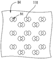
FIG. 5 is a top view of a plurality of film holes on an exemplary engine composite, according to one embodiment; and
FIG. 6 is a top view of a plurality of film holes on another exemplary engine composite, according to one embodiment.
Repeat use of reference characters in the present specification and drawings is intended to represent same or analogous features or elements of the invention.
Detailed Description
Reference now will be made in detail to embodiments of the invention, one or more examples of which are illustrated in the drawings. Each example is provided by way of explanation of the invention, not limitation of the invention. Indeed, it will be apparent to those skilled in the art that various modifications and variations can be made in the present invention without departing from the scope or spirit of the invention. For instance, features illustrated or described as part of one embodiment, can be used with another embodiment to yield a still further embodiment. Thus, it is intended that the present invention cover the modifications and variations of this invention provided they come within the scope of the appended claims and their equivalents.
As used herein, the terms "first," "second," and "third" may be used interchangeably to distinguish one component from another component and are not intended to indicate the position or importance of a single component.
The terms "upstream" and "downstream" refer to relative directions in a fluid pathway with respect to fluid flow. For example, "upstream" refers to the direction from which the fluid flows, while "downstream" refers to the direction to which the fluid flows.
As used herein, the phrases "consisting of CMC" and "consisting of CMC" shall mean a component that consists essentially of CMC. More specifically, the CMC component should include more CMC material than just one CMC material layer or coating. For example, a component constructed of CMC may consist essentially or entirely of or consist of CMC material, including more than about 50%, 60%, 70%, 80%, 90%, or 100% CMC material.
Referring now to the drawings, FIG. 1 shows a cross-sectional view of one embodiment of a gas turbine engine 10 usable within an aircraft, where the engine 10 is shown with a longitudinal or axial centerline axis 12 extending therethrough for reference purposes, in accordance with aspects of the present subject matter. In general, the engine 10 may include a core gas turbine engine (generally represented by reference numeral 14) and a fan section 16 positioned upstream thereof. The core engine 14 may generally include a generally tubular outer casing 18 defining an annular inlet 20. Additionally, the outer casing 18 may further enclose or support a booster compressor 22 for boosting the pressure of the air entering the core engine 14 to a first pressure level. The high-pressure, multi-stage, axial-flow compressor 24 may then receive pressurized air from the booster compressor 22 and further boost the pressure of such air. The pressurized air exiting the high pressure compressor 24 may then flow to a combustor 26 where fuel is injected into the pressurized air stream and the resulting mixture is combusted within the combustor 26. The high energy combustion products are channeled from combustor 26 along a hot gas path of engine 10 to a first (high pressure, HP) turbine 28 for driving high pressure compressor 24 via a first (high pressure, HP) drive shaft 30, and then to a second (low pressure, LP) turbine 32 for driving booster compressor 22 and fan section 16 via a second (low pressure, LP) drive shaft 34 generally coaxial with first drive shaft 30. After driving each of turbines 28 and 32, the combustion products may be discharged from core engine 14 via discharge nozzle 36 to provide propulsive injection thrust.
It should be appreciated that each turbine 28, 32 may generally include one or more turbine stages, and each stage includes a turbine nozzle and a downstream turbine rotor. As will be described below, the turbine nozzle may include a plurality of vanes disposed in an annular array about a centerline axis 12 of the engine 10 for modulating or otherwise directing a flow of combustion products through the turbine stages toward a corresponding annular array of rotor blades forming a portion of a turbine rotor. As is generally understood, the rotor blades may be coupled to a rotor disk of a turbine rotor, which in turn is rotationally coupled to a drive shaft of a turbine (e.g., drive shaft 30 or 34).
Additionally, as shown in FIG. 1, the fan section 16 of the engine 10 may generally include a rotatable axial fan rotor 38 configured to be surrounded by an annular fan casing 40. In a particular embodiment, the (LP) drive shaft 34 may be directly connected to the fan rotor 38, such as in a direct drive configuration. In an alternative configuration, the (LP) drive shaft 34 may be connected to the fan rotor 38 via a speed reduction device 37, such as a reduction gearbox in an indirect drive or gear drive configuration. Such speed reduction devices may be included between any suitable shafts/spools within engine 10 as needed or desired.
As will be appreciated by those of ordinary skill in the art, the fan casing 40 may be configured to be supported relative to the core engine 14 by a plurality of substantially radially extending, circumferentially spaced outlet guide vanes 42. Thus, the fan housing 40 may enclose the fan rotor 38 and its corresponding fan rotor blades 44. Moreover, a downstream section 46 of the fan casing 40 may extend across an exterior portion of the core engine 14 to define an auxiliary or bypass airflow duct 48 that provides additional propulsive jet thrust.
During operation of engine 10, it should be appreciated that an initial flow of air (represented by arrow 50) may enter engine 10 via an associated inlet 52 of fan housing 40. The air flow 50 then passes over the fan blades 44 and splits into a first compressed air flow (represented by arrow 54) moving through the conduit 48 and a second compressed air flow (represented by arrow 56) entering the booster compressor 22. The pressure of the second compressed air stream 56 then increases and enters the high pressure compressor 24 (as represented by arrow 58). After being mixed with fuel and combusted within the combustor 26, the combustion products 60 exit the combustor 26 and flow through the first turbine 28. Thereafter, the combustion products 60 flow through the second turbine 32 and exit the exhaust nozzle 36 to provide thrust to the engine 10.
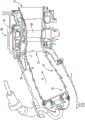
FIG. 2 is a side cross-sectional view of a combustor 26 and a first turbine 28 (i.e., a High Pressure (HP) turbine) from engine 10 of FIG. 1. Combustor 26 includes a deflector 76 and a combustor liner 77. Adjacent to the turbine blades 68 of the turbine 28 in the axial direction are sets of axially spaced stationary turbine vanes 72, with adjacent vanes 72 forming nozzles therebetween. The nozzles turn the combustion gases to better flow into the rotating blades so that maximum energy can be extracted by the turbine 28. As the hot combustion gas stream H passes along the exterior of the airfoil 72, the cooling fluid stream C passes over the airfoil 72 to cool the airfoil 72. The shroud assembly 78 is adjacent the rotating blades 68 to minimize flow losses in the turbine 28. A similar shroud assembly may also be associated with the LP turbine 32, the LP compressor 22, or the HP compressor 24.
One or more of the engine components of engine 10 include a film-cooled substrate in which the film holes of the embodiments further disclosed herein may be provided. Some non-limiting examples of engine components having film-cooled substrates may include vanes 68, vanes or nozzles 72, combustor deflectors 76, combustor liners 77, or shroud assemblies 78 depicted in fig. 1-2. Other non-limiting examples in which film cooling is used include turbine transition ducts and discharge nozzles.
FIGS. 3 and 4 are schematic cross-sectional views illustrating respective portions of an exemplary engine component 80 formed from a CMC substrate 82 defining at least one film hole 90 defined therein. The engine component 80 may be an engine component derived from the engine 10 of FIG. 1 and may be disposed in the flow of hot gases represented by arrow H. The flow of cooling fluid, represented by arrow C, may be supplied to cool the engine components. As discussed above with respect to fig. 1-2, in the case of a turbine engine, the cooling air may be the first compressed air stream 54 that bypasses the engine core 14, fluid from the LP compressor 22, or fluid from the HP compressor 24.
The engine component 80 includes a substrate 82 having a hot surface 84 facing the hot combustion gas flow H and a cooling surface 86 facing the cooling fluid C. The substrate 82 may form a wall of the engine component 80; the wall may be an outer or inner wall of the engine component 80. Regardless of the location or type of components within the engine, the hot surface 84 of the substrate 82 is exposed to the hot gases within the engine. The first engine component 80 may define at least one internal cavity or channel 88 that includes a cooling surface 86. The hot surface 84 may be an exterior surface of the engine component 80. In the case of a gas turbine engine, the hot surface 84 may be exposed to a gas having a temperature in the range of 1000 ℃ to 2000 ℃. Suitable materials for substrate 82 include, but are not limited to, steel, refractory metals such as titanium, or superalloys based on nickel, cobalt, or iron, and ceramic matrix composites. The superalloys may include those that are equiaxed, directionally solidified, and single crystal structures.
In one particular embodiment, the substrate 82 is constructed of a Ceramic Matrix Composite (CMC) material, which is a non-metallic material having high temperature properties. Exemplary CMC materials for such substrates 82 may include silicon carbide, silicon, silica, or alumina-based materials, and combinations thereof. Ceramic fibers may be embedded within the matrix, such as oxidation stable reinforcing fibers including monofilaments like sapphire and silicon carbide (e.g., SCS-6 of Textron corporation), and rovings and spun yarns including silicon carbide (e.g., NICATON @, TYRANNO @, of Ube Industries, and SYLRAMIC @, of Dow Corning), aluminum silicate (e.g., 440 and 480, of Nextel corporation), and chopped whiskers and fibers (e.g., 440 and SAFFIL @, of Nextel corporation), and optionally ceramic particles (e.g., oxides of silicon, aluminum, zirconium, yttrium, and combinations thereof) and inorganic fibers (e.g., pyrophyllite, wollastonite, mica, talc, kyanite, and montmorillonite). In one embodiment, the CMC material is formed of multiple layers (e.g., about 4 to about 10 layers) in its thickness.
The CMC material is formed into plies of material having a thickness of about 25 μm to about 475 μm, and most typically about 125 inches to about 400 inches. The thickness of the plies is generally determined by the size of the fiber bundle (filament tow) selected for use, and may vary with fiber diameter. For most of the applications contemplated herein, the plies are formed as a two-dimensional woven fabric, although one-dimensional fiber orientation may also be used. However, the methods of making the plies, placing the plies to form the component parts and other part fabrication techniques used in the composite industry are not meant to limit the invention. The plies are placed to form the shape of the formed article, and the angle of adjacent plies may be varied depending on the desired in-plane strength. Components that may be made using these CMC materials include, but are not limited to, turbine blades, turbine vanes, turbine shrouds, and combustor liners, casings, heat shields, and diffusers. These hot section components all benefit from the use of cooling air to provide sufficient cooling to achieve heat transfer during engine operation, thereby extending their range of use.
The engine component 80 also includes one or more film holes 90 defined by the substrate 82 and extending through the substrate 82 that provide fluid communication between the internal cavity 88 and the hot surface 84 of the engine component 80. The film hole 90 has an inlet 92 provided on the cooling surface 86 of the substrate 82, an outlet 94 provided on the hot surface 84, and a passage 96 connecting the inlet 92 and the outlet 94. Channel 96 is generally defined within passage 96 between upstream inner surface 95 and downstream inner surface 97. Although only one film hole 90 is shown in fig. 3, it should be understood that the engine component 80 may be provided with a plurality of film holes 90 that may be arranged in any desired configuration on the engine component 80 (e.g., as shown in fig. 5 and 6).
Note that in any of the embodiments discussed herein, although the base 82 is shown as being substantially planar (or flat), it should be understood that the base 82 may be curved for many engine components 80. However, the curvature of the substrate 82 may be slight compared to the size of the film holes 90, and thus the substrate 82 is shown as flat for purposes of discussion and illustration. Whether the substrate 82 is flat or partially curved relative to the film hole 90, the hot and cold surfaces 84, 86 may be parallel to each other as shown in the figures, or may lie in non-parallel planes.
During operation, the cooling fluid flow C is supplied to the internal cavity 88, into the inlet 92, through the passages 96 of the film holes 90, and out the outlet 94 to create a thin layer or film of cooling fluid (e.g., air drawn from the compressor) on the hot surface 84, protecting the hot surface from the hot combustion gas flow H. However, the film holes 90 have a relatively high heat transfer coefficient on the upstream and downstream inner surfaces 95, 97, which may facilitate the film holes 90 to act as a reinforced heat sink. However, because CMC materials have a much lower thermal conductivity (e.g., about half) than metals, the film holes 90 and the gas flow therein significantly increase the locally generated thermal gradients within the CMC, resulting in thermal stresses within the CMC substrate 82.
Fig. 3 and 4 show a low conductivity coating 110 on at least a portion of the upstream inner surface 95 and the downstream inner surface 97. In certain embodiments, the low conductivity coating 110 may be a Thermal Barrier Coating (TBC) or an Environmental Barrier Coating (EBC). For example, the low-conductivity coating 110 may include multiple layers. For example, an EBC may include a bond coat (e.g., comprising silicon or silicon dioxide), one or more layers formed from one or more rare earth silicates (e.g., one or more of a mullite layer, a mullite-alkaline earth aluminosilicate mixture layer, a Yttrium Monosilicate (YMS) layer, a ytterbium-doped yttrium disilicate (YbYDS) layer, a Barium Strontium Aluminosilicate (BSAS) layer, etc.), and so forth. The low-conductivity coating 110 overlies any other coating (e.g., EBC and/or TBC) that may be on the hot surface 84 of the substrate 82.
The low-conductivity coating 110 may have a thermal conductivity of at most about one-tenth of the thermal conductivity of the CMC substrate 100 in order to inhibit the formation of thermal stress within the substrate 100. That is, the thermal conductivity of the CMC substrate is 10 times (or more) the thermal conductivity of the coating 110. For example, the low-conductivity coating 110 may have a thermal conductivity of at most about one-fiftieth of the thermal conductivity of the CMC substrate 100. That is, the thermal conductivity of the CMC substrate is 50 times (or more) the thermal conductivity of the coating 110. Thus, the coating 110 may protect the underlying CMC substrate 100, particularly in and around the film pores, from forming significant local temperature gradients therein.
As shown in fig. 3 and 4, the low-conductivity coating 110 is positioned on at least a portion of the hot surface 84 of the substrate 82, on at least a portion of the inner surfaces 95, 97 defined within the channel (e.g., at least a portion of the upstream inner surface 95 and/or at least a portion of the downstream inner surface 97), and/or on at least a portion of the cold surface 86 of the substrate 82. Although shown on a portion of the hot surface 84 of the substrate 82, the entire inner surface 95, 97 within the channel, and a portion of the cold surface 86, the low-conductivity coating 110 can be applied on each of the respective surfaces 84, 86, 95, 97 (in whole or in part), as desired. For example, the low-conductivity coating 110 may extend from the outlet 94 to the inlet 92 on the upstream inner surface 95 and/or the downstream inner surface 97. In a particular embodiment, the coating 110 completely covers all surfaces defined within the channel.
In one embodiment, the low-conductivity coating 110 extends around at least 50% of the upstream edge 102 of the outlet 94 (e.g., around at least 75% of the upstream edge of the outlet), such as shown in fig. 6. Similarly, in one embodiment, the low-conductivity coating 110 may extend around at least 50% of the downstream edge 104 of the outlet 94 (e.g., around at least 75% of the downstream edge of the outlet). For example, the low-conductivity coating 110 circumferentially surrounds the outlet 94 defined in the hot surface 84, as shown in fig. 5. Similarly, the low-conductivity coating 110 circumferentially surrounds the inlet 96 defined in the cold surface 86.
In certain embodiments, the coating 110 may be an extension of any or all of a Thermal Barrier Coating (TBC), an environmental barrier coating, an adherent compliant coating, or the like, that extends across the entire thermal surface 84. However, in other embodiments, the low-conductivity coating 110 may only partially extend from the film holes. For example, the low-conductivity coating 110 may have an average length extending away from the respective film hole edge (e.g., the upstream edge 102 and/or the downstream edge 104) that is about 0.5 to about 10 (e.g., about 0.5 to about 5) times an outlet diameter measured from the upstream inner surface 102 to the downstream inner surface 104 in the direction of the hot combustion gas flow H. As shown in the exemplary embodiment of fig. 3 and 4, the outer ends 113, 115 of the low-conductivity coating 110 (away from the respective film hole edges) are tapered relative to the hot surface 84 in order to mitigate any effect on the air flow across the film hole 90. However, in other embodiments, the outer ends 113, 115 may have different orientations relative to the outer surface 84, such as perpendicular to the hot surface 84, curved, stepped, and so forth.
Similarly, the coating 110 may extend across the entire cooling surface 86, or may only partially extend from the inlet 92 of the film hole 90. For example, the low-conductivity coating 110 may have an average length extending away from the respective film hole edge (e.g., upstream edge and/or downstream edge) of the inlet 92 that is about 0.5 to about 10 times (e.g., about 0.5 to about 5 times) the inlet diameter measured from the upstream inner surface to the downstream inner surface in the direction of the hot combustion gas flow H. As shown in the exemplary embodiments of fig. 3 and 4, the outer ends may be tapered relative to the cooling surface 86 or may have different orientations relative to the cooling surface 86, such as perpendicular to the cooling surface 86, curved, stepped, and so forth.
In a particular embodiment, the low conductive coating 110 has a thickness of about 10 μm to about 1500 μm on the respective surface of the substrate 82, but may vary in thickness depending on the location of the coating. For example, in one embodiment, the low-conductivity coating 110 has a thickness H on the hot surface 84 defined from the outer surface 106 of the low-conductivity coating 110 to the hot surface 84 of the substrate 82 in a direction perpendicular to the flow of hot combustion gases H. In one embodiment, the thickness h is about 1500 μm or less, preferably about 25 μm to about 500 μm. In most embodiments, the thickness h', h ″ on the inner surfaces 95, 97 within the membrane pores 90, respectively, is about 10 μm to about 130 μm. Thus, in one particular embodiment, the thickness h of the low conductivity coating 110 on the hot surface 84 is greater than the thicknesses h', h ″ on the inner surfaces 95, 97.
The film holes 90 may have any shape, such as a tapered cross-section (e.g., expanding or contracting), as desired. In addition, the film holes 90 may include any features therein, including, for example, a metering section (for metering the mass flow rate of the cooling fluid flow C) and a diffusion section (in which the cooling fluid C may expand to form a wider cooling film), and/or other features.
This written description uses examples to disclose the invention, including the best mode, and also to enable any person skilled in the art to practice the invention, including making and using any devices or systems and performing any incorporated methods. The patentable scope of the invention is defined by the claims, and may include other examples that occur to those skilled in the art. Such other examples are intended to be within the scope of the claims if they include structural elements that do not differ from the literal language of the claims, or if they include equivalent structural elements with insubstantial differences from the literal languages of the claims.
List of part labels
10 gas turbine engine
12 centerline axis
14 core gas turbine engine
16 fan section
18 outer casing
20-shaped inlet
22 booster compressor
24 compressor
26 burner
28 high-pressure turbine
30 high pressure driving shaft
32 low pressure turbine
34 low pressure driving shaft
36 discharge nozzle
37 speed reduction device
38 fan rotor
40 Fan case
42 outlet guide vane
44 fan rotor blade
46 downstream section
48 auxiliary air flow conduit
50 initial air flow
52 inlet
54 first compressed air stream
56 second compressed air stream
58 arrow
60 products of combustion
68 turbine blade
72 turbine airfoil
76 deflector
77 Combustion liner
78 shroud assembly
80 engine component
82 base
84 hot surface
85 partial outer surface tangent
86 cooling surface
88 internal cavity
90 film hole
92 inlet
94 outlet
95 upstream inner surface
96 channels
97 downstream inner surface
102 (of the substrate) upstream edge
104 (of the substrate) downstream edge
110 environmental barrier coating
112 upstream inner surface
113 outer end
114 downstream inner surface
115 outer end
Claims (9)
1. An engine component of a gas turbine engine for generating a flow of hot combustion gases, comprising:
a substrate constructed of a CMC material and having a hot surface facing the flow of hot combustion gases and a cooling surface facing a flow of cooling fluid, wherein the substrate defines a film hole extending through the substrate and having an inlet provided on the cooling surface, an outlet provided on the hot surface, and a channel connecting the inlet and the outlet; and
a coating on at least a portion of the hot surface and on all surfaces defined within the channel;
wherein the CMC material has a first thermal conductivity, the coating has a second thermal conductivity, and the first thermal conductivity is greater than the second thermal conductivity; and
wherein the first thermal conductivity is 10 times or more greater than the second thermal conductivity.
2. The engine component of claim 1, wherein the coating is on at least a portion of the hot surface, on at least a portion of an inner surface defined within the channel, and on at least a portion of the cooling surface.
3. The engine component of claim 1, wherein the coating circumferentially surrounds the hot surface around an outlet defined in the hot surface.
4. The engine component of claim 3, wherein the coating extends across the entire hot surface of the substrate.
5. The engine component of claim 1, wherein the coating has a thickness defined from an outer surface of the coating to a hot surface of the substrate in a direction perpendicular to a flow of hot combustion gases, the thickness being 1000 μm or less.
6. The engine component of claim 1, wherein the coating extends around at least 50% of a downstream edge of the outlet.
7. The engine component of claim 1, wherein the coating overlies at least a portion of the upstream inner surface and at least a portion of the downstream inner surface.
8. The engine component of claim 7, wherein the coating on the upstream inner surface passes at least 50% of the depth from the outlet to the inlet, and wherein the coating on the downstream inner surface passes at least 50% of the depth from the outlet to the inlet, the coating overlying a thermal barrier coating forming a hot surface of the substrate.
9. A gas turbine engine, comprising:
a compressor;
a burner;
a turbine; and
the engine component of any preceding claim.
Applications Claiming Priority (2)
| Application Number | Priority Date | Filing Date | Title |
|---|---|---|---|
| US14/955261 | 2015-12-01 | ||
| US14/955,261 US10472972B2 (en) | 2015-12-01 | 2015-12-01 | Thermal management of CMC articles having film holes |
Publications (2)
| Publication Number | Publication Date |
|---|---|
| CN106930837A CN106930837A (en) | 2017-07-07 |
| CN106930837B true CN106930837B (en) | 2021-10-15 |
Family
ID=57421724
Family Applications (1)
| Application Number | Title | Priority Date | Filing Date |
|---|---|---|---|
| CN201611090122.XA Active CN106930837B (en) | 2015-12-01 | 2016-12-01 | Thermal Management of CMC Articles with Membrane Pores |
Country Status (6)
| Country | Link |
|---|---|
| US (1) | US10472972B2 (en) |
| EP (1) | EP3176375A1 (en) |
| JP (1) | JP2017101673A (en) |
| CN (1) | CN106930837B (en) |
| BR (1) | BR102016028108A2 (en) |
| CA (1) | CA2949672A1 (en) |
Families Citing this family (12)
| Publication number | Priority date | Publication date | Assignee | Title |
|---|---|---|---|---|
| US10443395B2 (en) * | 2016-03-18 | 2019-10-15 | General Electric Company | Component for a turbine engine with a film hole |
| US10731469B2 (en) | 2016-05-16 | 2020-08-04 | Raytheon Technologies Corporation | Method and apparatus to enhance laminar flow for gas turbine engine components |
| US10539026B2 (en) | 2017-09-21 | 2020-01-21 | United Technologies Corporation | Gas turbine engine component with cooling holes having variable roughness |
| KR102067103B1 (en) * | 2018-04-05 | 2020-01-16 | 두산중공업 주식회사 | System for estimating turbine temperature |
| US11286792B2 (en) * | 2019-07-30 | 2022-03-29 | Rolls-Royce Plc | Ceramic matrix composite vane with cooling holes and methods of making the same |
| US11585224B2 (en) | 2020-08-07 | 2023-02-21 | General Electric Company | Gas turbine engines and methods associated therewith |
| US11927111B2 (en) | 2022-06-09 | 2024-03-12 | General Electric Company | Turbine engine with a blade |
| US11898460B2 (en) | 2022-06-09 | 2024-02-13 | General Electric Company | Turbine engine with a blade |
| US11821337B1 (en) * | 2022-08-05 | 2023-11-21 | Rtx Corporation | Internal aluminide coating for vanes and blades and method of manufacture |
| US11976571B1 (en) * | 2022-12-13 | 2024-05-07 | Rtx Corporation | Machinable coating with thermal protection |
| US12359575B2 (en) | 2022-12-13 | 2025-07-15 | Rtx Corporation | Machinable coating with thermal protection |
| US20260078685A1 (en) * | 2024-09-19 | 2026-03-19 | Rtx Corporation | Thermal barrier coating for edge component |
Citations (5)
| Publication number | Priority date | Publication date | Assignee | Title |
|---|---|---|---|---|
| CN1670337A (en) * | 2004-03-17 | 2005-09-21 | 联合工艺公司 | Turbine components with thermal barrier coatings |
| EP1632720A1 (en) * | 2004-09-03 | 2006-03-08 | General Electric Company | Adjusting airflow in turbine component by depositing an overlay metallic coating |
| CN101429893A (en) * | 2007-10-18 | 2009-05-13 | 通用电气公司 | Air cooled gas turbine components and methods of manufacturing and repairing the same |
| CN101879661A (en) * | 2009-05-05 | 2010-11-10 | 通用电气公司 | Systems and methods for improved film cooling |
| WO2015065587A1 (en) * | 2013-11-04 | 2015-05-07 | United Technologies Corporation | Coated cooling passage |
Family Cites Families (26)
| Publication number | Priority date | Publication date | Assignee | Title |
|---|---|---|---|---|
| GB2051964B (en) | 1979-06-30 | 1983-01-12 | Rolls Royce | Turbine blade |
| DE59601728D1 (en) | 1995-07-25 | 1999-05-27 | Siemens Ag | PRODUCT WITH A METAL BASE WITH COOLING CHANNELS AND THEIR PRODUCTION |
| US5771577A (en) | 1996-05-17 | 1998-06-30 | General Electric Company | Method for making a fluid cooled article with protective coating |
| US6544346B1 (en) | 1997-07-01 | 2003-04-08 | General Electric Company | Method for repairing a thermal barrier coating |
| JP2001521989A (en) | 1997-11-03 | 2001-11-13 | シーメンス アクチエンゲゼルシヤフト | Method for forming a film and apparatus for performing the method |
| US6332926B1 (en) | 1999-08-11 | 2001-12-25 | General Electric Company | Apparatus and method for selectively coating internal and external surfaces of an airfoil |
| US6441341B1 (en) * | 2000-06-16 | 2002-08-27 | General Electric Company | Method of forming cooling holes in a ceramic matrix composite turbine components |
| US6339879B1 (en) | 2000-08-29 | 2002-01-22 | General Electric Company | Method of sizing and forming a cooling hole in a gas turbine engine component |
| JP3600911B2 (en) * | 2001-01-25 | 2004-12-15 | 川崎重工業株式会社 | Liner support structure for annular combustor |
| EP1275747B1 (en) | 2001-07-11 | 2011-02-23 | Alstom Technology Ltd | Method for coating a high temperature resistant article with a thermal protection covering and high temperature resistant article |
| DE10143153A1 (en) | 2001-09-03 | 2003-03-20 | Rolls Royce Deutschland | Turbine blade for a gas turbine with at least one cooling recess |
| US6881439B2 (en) | 2002-12-04 | 2005-04-19 | General Electric Company | Aluminide coating process |
| US6926496B2 (en) | 2002-12-31 | 2005-08-09 | General Electric Company | High temperature turbine nozzle for temperature reduction by optical reflection and process for manufacturing |
| US20050220618A1 (en) | 2004-03-31 | 2005-10-06 | General Electric Company | Counter-bored film-cooling holes and related method |
| US20060280955A1 (en) | 2005-06-13 | 2006-12-14 | Irene Spitsberg | Corrosion resistant sealant for EBC of silicon-containing substrate and processes for preparing same |
| GB2429515B (en) * | 2005-08-11 | 2008-06-25 | Rolls Royce Plc | Cooling method and apparatus |
| US7622160B2 (en) | 2006-07-28 | 2009-11-24 | General Electric Company | Method for concurrent thermal spray and cooling hole cleaning |
| US8141370B2 (en) * | 2006-08-08 | 2012-03-27 | General Electric Company | Methods and apparatus for radially compliant component mounting |
| US8257809B2 (en) | 2007-03-08 | 2012-09-04 | Siemens Energy, Inc. | CMC wall structure with integral cooling channels |
| US8192831B2 (en) * | 2008-12-10 | 2012-06-05 | General Electric Company | Articles for high temperature service and methods for their manufacture |
| EP2216509A1 (en) * | 2009-02-04 | 2010-08-11 | Siemens Aktiengesellschaft | Turbine component with easily removable protective layer, turbine component set, a turbine and method for protecting a turbine component |
| US9624583B2 (en) | 2009-04-01 | 2017-04-18 | Rolls-Royce Corporation | Slurry-based coating techniques for smoothing surface imperfections |
| US8397511B2 (en) * | 2009-05-19 | 2013-03-19 | General Electric Company | System and method for cooling a wall of a gas turbine combustor |
| US8460760B2 (en) | 2010-11-30 | 2013-06-11 | United Technologies Corporation | Coating a perforated surface |
| US10113435B2 (en) * | 2011-07-15 | 2018-10-30 | United Technologies Corporation | Coated gas turbine components |
| JP6184172B2 (en) | 2013-05-29 | 2017-08-23 | 三菱日立パワーシステムズ株式会社 | Al coating method and gas turbine blade manufacturing method |
-
2015
- 2015-12-01 US US14/955,261 patent/US10472972B2/en active Active
-
2016
- 2016-11-22 CA CA2949672A patent/CA2949672A1/en not_active Abandoned
- 2016-11-29 EP EP16201013.6A patent/EP3176375A1/en not_active Withdrawn
- 2016-11-29 JP JP2016230728A patent/JP2017101673A/en active Pending
- 2016-11-30 BR BR102016028108-3A patent/BR102016028108A2/en not_active Application Discontinuation
- 2016-12-01 CN CN201611090122.XA patent/CN106930837B/en active Active
Patent Citations (5)
| Publication number | Priority date | Publication date | Assignee | Title |
|---|---|---|---|---|
| CN1670337A (en) * | 2004-03-17 | 2005-09-21 | 联合工艺公司 | Turbine components with thermal barrier coatings |
| EP1632720A1 (en) * | 2004-09-03 | 2006-03-08 | General Electric Company | Adjusting airflow in turbine component by depositing an overlay metallic coating |
| CN101429893A (en) * | 2007-10-18 | 2009-05-13 | 通用电气公司 | Air cooled gas turbine components and methods of manufacturing and repairing the same |
| CN101879661A (en) * | 2009-05-05 | 2010-11-10 | 通用电气公司 | Systems and methods for improved film cooling |
| WO2015065587A1 (en) * | 2013-11-04 | 2015-05-07 | United Technologies Corporation | Coated cooling passage |
Also Published As
| Publication number | Publication date |
|---|---|
| EP3176375A1 (en) | 2017-06-07 |
| CA2949672A1 (en) | 2017-06-01 |
| CN106930837A (en) | 2017-07-07 |
| US10472972B2 (en) | 2019-11-12 |
| BR102016028108A2 (en) | 2017-07-18 |
| US20170152749A1 (en) | 2017-06-01 |
| JP2017101673A (en) | 2017-06-08 |
Similar Documents
| Publication | Publication Date | Title |
|---|---|---|
| US10472972B2 (en) | Thermal management of CMC articles having film holes | |
| US20170089579A1 (en) | Cmc articles having small complex features for advanced film cooling | |
| US11111858B2 (en) | Cool core gas turbine engine | |
| US10662786B2 (en) | CMC articles having small complex features for advanced film cooling | |
| US20180216575A1 (en) | Cool core gas turbine engine | |
| EP3617450A1 (en) | Cmc component including directionally controllable cmc insert and method of fabrication | |
| US10563867B2 (en) | CMC articles having small complex features for advanced film cooling | |
| US10605087B2 (en) | CMC component with flowpath surface ribs | |
| US20190085705A1 (en) | Component for a turbine engine with a film-hole | |
| US20170122109A1 (en) | Component for a gas turbine engine | |
| CN104929694B (en) | The method of component and manufacture with compound angled air-circulation features | |
| CA2948978A1 (en) | Ht enhancement bumps/features on cold side | |
| US20200141247A1 (en) | Component for a turbine engine with a film hole | |
| US10094226B2 (en) | Component for a gas turbine engine with a film hole | |
| US10519779B2 (en) | Radial CMC wall thickness variation for stress response | |
| US11466574B2 (en) | Method and apparatus to enhance laminar flow for gas turbine engine components | |
| US10577949B2 (en) | Component for a gas turbine engine | |
| WO2018071260A1 (en) | Gas turbine engine | |
| US12304177B2 (en) | Ceramic matrix composite (CMC) component resistant to edge cracks | |
| US10309254B2 (en) | Nozzle segment for a gas turbine engine with ribs defining radially spaced internal cooling channels |
Legal Events
| Date | Code | Title | Description |
|---|---|---|---|
| PB01 | Publication | ||
| PB01 | Publication | ||
| SE01 | Entry into force of request for substantive examination | ||
| SE01 | Entry into force of request for substantive examination | ||
| GR01 | Patent grant | ||
| GR01 | Patent grant |