Drive belt with a set of nested steel flexible rings
Technical Field
The present invention relates to a drive belt for use in a well-known pulley-type continuously variable transmission or CVT, typically used in motor vehicles, for transmitting power generated by the engine of the motor vehicle to its driven wheels at a variable ratio of speed/torque. In this transmission, a transmission belt is provided on two pulleys each including a pair of conical disks defining a conical circumferential groove, and respective circumferential portions of the transmission belt are located in the grooves while being sandwiched therebetween by the pulley disks.
Background
A known type of drive belt is described in detail in EP 1216366 a1, which particular belt type is known in the art as a push type drive belt. Such known drive belts comprise a plurality of transverse segments of steel, each transverse segment having at least one, but usually two, recesses in which in each case a circumferential portion of a set of a plurality of mutually concentrically nested flexible steel rings of the drive belt is accommodated. In the prior art, the transverse segments are also referred to as transverse elements or components, the loops are referred to as hoops, loops or bands, and the loop groups are referred to as loop carriers. In the known drive belt, the transverse segments are not connected to the ring set but are slidable along their circumference while being thereby restrained in axial and radial directions perpendicular thereto.
It is known that in this type of transmission the transverse elements are subjected to a radially outwardly directed force at the location of the two pulleys, i.e. where the transverse elements are clamped between the sheaves of each pulley, which acts as a normal force against the radially innermost ring of the ring set, thus creating a tensile force there. Due to this tension, the radially innermost ring is elongated, i.e. stretched. However, this stretching of the radially innermost ring is resisted by the presence of the immediately adjacent ring, i.e. the ring immediately adjacent the innermost ring, of the respective set of rings. The normal force is therefore also partially supported on such a ring in the immediate vicinity and thus also generates a tensile force there. The force is propagated through the entire ring set until all of the rings are tensioned, each of which participates in carrying the entire belt tension.
In the latter respect, EP 1216366 a1 teaches that, assuming that the rings nest within each other without any gaps between each other in the radial direction, the entire belt tension will be equally distributed between the individual rings of the ring set. In this case, the normal force acting on the respective ring decreases uniformly from the radial force level on the radially inwardly directed surface (i.e., the inner side) of the innermost ring to zero on the radially outwardly directed surface (i.e., the outer side) of the radially outermost ring of the ring set. In practice in the manufacture of rings, ring sets and drive belts in large numbers, it is practically impossible or at least very expensive to provide a zero radial clearance between each pair of adjacent rings of a drive belt ring set. Thus, in practice some (small amount of) positive radial clearance is allowed between adjacent rings.
It is also known in the art to reduce the tension on the radially innermost ring and the radially outermost ring in a ring set relative to the other rings in the ring set to compensate for the additional contact stress that the innermost and outermost rings are subjected to as a result of their contact with the transverse segments. In particular in this regard, a small negative gap is disposed between the radially innermost ring pair of the ring set to reduce tension on the radially innermost ring, and a large positive gap is disposed between the radially outermost ring pair of the ring set to reduce tension on the radially outermost ring, at least relative to the gaps disposed between other pairs of adjacent rings of the ring set.
Disclosure of Invention
In the context of the present disclosure, the radial gap between a pair of adjacent rings in a ring set is defined as: the difference between the outer circumferential length of the radial wrappings of the ring pairs, i.e. the inner ring, and the inner circumferential length of the radial wrappings of the ring pairs, i.e. the outer ring, is divided by 2pi (2 pi). By this definition, at least for rings having a thickness in the range of 100 to 300 microns, more particularly 150 to 200 microns, and having a circumferential length in the range of 500 to 1000 millimeters, the nominal value of the radial clearance, i.e. the manufacturing average, is 3 microns plus/minus a 7 micron tolerance. However, it is preferred to allow only positive radial gaps, for example from 0 to 10 microns, between pairs of adjacent rings of a ring set, with a nominal value of the radial gap or a manufacturing average lying substantially in the middle of such a tolerance range (tolerance window). In the latter case, the ring set can be assembled from individual rings relatively easily.
During operation, the individual rings of the ring set may-in fact-slide relative to each other in their circumferential direction. This relative movement or sliding of the rings in the ring sets is geometrically determined because the rings operate in slightly different gear ratios in the transmission because each ring has a unique radial position in the ring set at the transmission pulley. While this loop slip is not detrimental to the function of the belt itself, it does cause some power loss due to friction between adjacent loops. Such a power loss between each pair of adjacent rings in a ring set is determined by the product of the locally prevailing normal force in the sliding contact between the adjacent rings and the coefficient of friction in such contact, which in turn depends on several parameters, such as contact pressure, sliding speed, etc., although such a power loss due to friction seems unavoidable in this type of drive belt, a reduction of the power loss, at least on average during operation of the drive belt in the transmission, can still be achieved according to the present disclosure.
According to the present disclosure, the above object is achieved by: a radial gap is provided between at least one ring pair of adjacent rings in the ring set other than the radially innermost ring pair and the radially outermost ring pair, which is significantly larger than the radial gap provided between the other ring pairs (i.e. other than the radially innermost and outermost ring pairs), for example at least twice as large on average. In particular, according to the present disclosure, in high volume manufacturing, the nominal value of such a larger radial clearance between said at least one ring pair of the drive belt is defined to exceed the nominal radial clearance provided between said other ring pairs by at least the following magnitude: the tolerance for such nominal values applies. Thus, for the standard 5 micron radial gap described above and the 5 micron standard manufacturing tolerance for such gaps, the at least one ring pair of adjacent rings has a nominal radial gap of at least 15 microns plus/minus 5 microns.
When a transmission having a drive belt according to the present disclosure is only partially loaded with respect to its maximum possible load, the clamping force exerted on the drive belt by the pulleys is relatively low, and therefore the tension force of the loop set is also relatively low. In the case of rings of a ring set which are nested one within the other without any radial play between one another in the radial direction, the ring set as a whole is also taut, even under such low tensions, and normal forces, and frictional losses associated therewith, are present between all pairs of adjacent rings. However, due to the large radial gap between at least one pair of adjacent rings of a ring set according to the present disclosure, only a portion of the rings of the ring set, i.e., those rings that are positioned radially inward with respect to the large radial gap, are tensioned by the low pulley clamping force. Thus, virtually no normal force and advantageously no frictional losses occur between the rings of those ring sets which are positioned radially outward with respect to the larger radial gap. Alternatively, according to the present disclosure, the drive belt, in particular the ring set thereof, is designed such that: in a defined partial load situation of the transmission, the tension of the rings located radially inwards with respect to the larger radial gap due to the pulley clamping force does not overlap, i.e. close, such a gap, whereby the rings located radially outwards with respect to the larger radial gap are neither tensioned nor subjected to normal forces, so that no or substantially no frictional losses occur.
When the transmission load increases, the clamping force likewise increases with part of normal transmission operation until, at a certain point, the larger radial gap between the at least one ring pair of adjacent rings is bridged by the stretching of the radially inner ring of such ring pair. Above this variator load, the radially outer ring of the respective ring pair is also tensioned and begins to carry part of the load. Obviously, the ring set is designed overall: so that at maximum transmission load, all of its rings are tensioned and take up a corresponding share in carrying such load.
Preferably, in accordance with the present disclosure, at least a plurality of the radially inner ring pairs of a ring set have a conventional, relatively small radial gap, with a larger radial gap in accordance with the present disclosure being provided only between adjacent rings that are closer to the radially outer side of the ring set. In particular, if the ring set comprises N individual rings, the innermost 30-40% of the rings thereof are preferably nested with one another with a conventional, relatively small radial clearance, while at least one of the remaining rings of the ring set, other than the outermost ring pair, has a relatively large radial clearance. More particularly, in this respect, if the ring set comprises, for example, 12 rings, it can be divided into 3 groups of 4 rings each, with a large radial gap being provided between the 4 th and 5 th rings of the ring set (for example counted in the radially outward direction) and between the 8 th and 9 th rings of the ring set. In this case, at lower transmission loads, only the first four inner rings of the ring set are tensioned and the frictional losses between the rings are minimized. At average variator load, 8 rings are involved in carrying the full belt tension, and at the highest variator load all rings are involved in carrying the maximum belt tension.
In the above, it appears feasible, and even advantageous, to provide a large radial gap between all adjacent rings of a ring set. However, according to the present disclosure, this may at least compromise the life of the radially innermost ring of the ring set. In sum, the innermost ring is additionally strained relative to the outermost ring of the ring set when gradually stretched to close the gap between all rings of the ring set. Thus, it is advantageous to combine a larger radial gap provided according to the present disclosure between at least one pair of adjacent rings of a ring set with a smaller nominal radial gap and tolerance value provided between the remaining pair of adjacent rings of the ring set.
Drawings
The above-described principles and features of the novel transverse element and its proposed manufacturing method will now be further elucidated in connection with the accompanying drawings, in which:
FIG. 1 presents a schematic depiction of an embodiment of a well-known continuously variable transmission having two pulleys and a drive belt;
figure 2 presents a cross-sectional view of a schematic depiction of a known drive belt comprising transverse elements made of steel and ring sets;
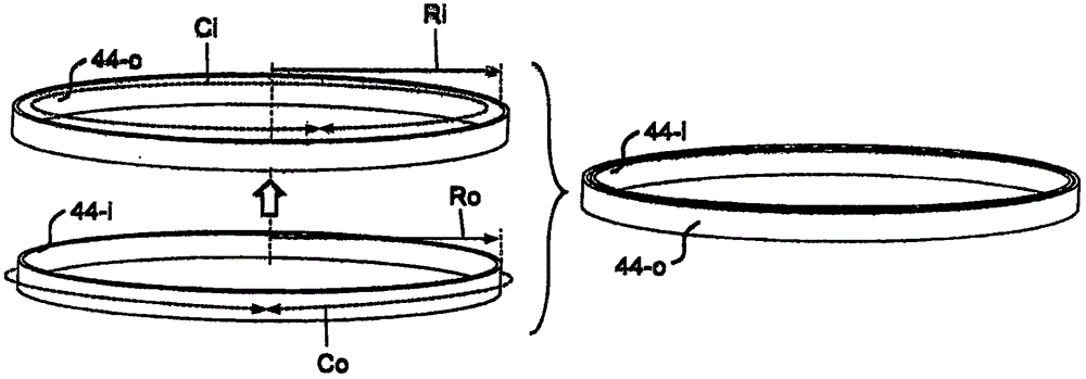
figure 3 schematically illustrates parameters of the radial gap between two adjacent rings or ring pairs of a drive belt ring set;
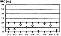
FIG. 4 is a graph of nominal and nominal values of radial clearance between pairs of adjacent rings of a drive belt ring set as commonly applied in the prior art;
FIG. 5 is a graph of nominal and tolerance values of radial gaps between pairs of adjacent rings of a ring set in accordance with a possible embodiment of the drive belt falling within the scope of the present disclosure; and
FIG. 6 is a graph illustrating the load share of each ring within a ring set of a plurality of ring sets.
Detailed Description
Fig. 1 illustrates the central components of a known continuously variable transmission or CVT as is commonly applied in automotive transmission systems between its engine and driven wheels. The transmission comprises two pulleys 1, 2 each provided with a pair of conical pulley discs 4, 5 mounted on a pulley shaft 6 or 7, defining between the pulley discs 4, 5 a circumferential pulley groove which is mainly V-shaped. Each pulley sheave 4, 5, i.e. at least one pulley sheave 4 of the pulley sheaves of each pulley 1, 2, is axially movable along a pulley shaft 6, 7 of the respective pulley 1, 2. A drive belt 3 is wound around the pulleys 1, 2 in pulley grooves for transmitting a rotational movement and an accompanying torque between the pulley shafts 6, 7.
The transmission usually also comprises an actuating device which during operation exerts an axially directed clamping force on said axially movable pulley discs 4 of each pulley 1, 2, which force is directed towards the respective other pulley disc 5 of the pulley 1, 2, so that the drive belt 3 is clamped between these discs 4, 5 of the pulley 1, 2. The clamping force not only determines the friction between the drive belt 3 and the respective pulley 1, 2, but also defines between the pulley discs 4, 5 the radial position R of the drive belt 3 at the respective pulley 1, 2, which radial position R defines the transmission gear ratio between the pulley shafts 6, 7.
An embodiment of the known drive belt 3 is illustrated in more detail in figure 2 with a cross section directed in the circumferential direction of the drive belt 3. The drive belt 3 is illustrated as comprising two sets 31 of flat, thin, i.e. band-shaped, flexible metal rings 44 which are nested into one another to form the ring set 31. In fig. 2, each such ring set 31 is illustrated as being made up of 5 individual rings 44, but in practice there are mostly 6, 9, 10 or 12 rings 44 per ring set 31. The drive belt 3 further comprises a plurality of transverse elements 32 mounted along its circumference on the ring set 31. Each ring set 31 is accommodated in a respective recess or notch 33 defined by the transverse element 32 on either lateral side of the transverse element 32, i.e. on either axial side of a central portion 35 of the transverse element 32. The notch 33 of the transverse element 32 is located between a bottom part 34 and an upper part 36 of the transverse element 32, as seen in general in a radial direction with respect to the drive belt 3. On the axial side of said bottom part 34, the transverse element 32 has a contact surface 37 for frictional contact with the pulley discs 4, 5.
During operation, the transverse elements 32 are subjected to a pulley clamping force by their respective contact surfaces 37, said contact surfaces 37 being positioned with respect to each other at an angle phi which substantially matches the angle theta of the V-shaped pulley groove, so that the transverse elements 32 are urged in a radially outward direction by the application of the pulley clamping force, whereby the ring set 31 is tensioned. Due to this tensioning of the ring set 31 in combination with the relative movement naturally occurring between the individual rings 44 of the ring set 31 during operation, frictional losses are generated in the contact between pairs of adjacent rings 44 of the ring set 31.
Although the individual rings 44 of a ring set are nested, i.e., concentrically assembled with minimal tolerances, there is generally some gap between adjacent rings 44 of a ring set 31, i.e., between each pair of radially inner and outer rings 44-i, 44-o in a ring set 31. The current relevant definition of these gaps is given below with reference to fig. 3. In FIG. 3, the respective radially inner ring 44-i is illustrated as having an outer circumference Co that is slightly smaller than the inner circumference Ci of the respective radially outer ring 44-o. When the two rings 44-i and 44-o are nested within each other, there will be some positive gap between them. This ring pair gap RPC is defined in the radial direction as the difference between the inner diameter Ri of the radially outer ring 44-o and the outer diameter Ro of the radially inner ring 44-i when the rings are positioned in an annular attitude.
The chart of fig. 4 provides one embodiment of a ring-to-ring gap RPC that may actually be applied when assembling the ring set 31 from individually manufactured (semi-finished) rings 44. On the horizontal axis of the diagram in fig. 4, successive pairs of adjacent rings 44 of the ring set 31 are listed, which in total comprise 10 rings 44, starting from a first ring pair 1-2 consisting of the radially innermost and the radially innermost second ring 44 of the ring set 31, to a 9 th and ending with the last ring pair 9-10 consisting of the radially outermost and the radially outermost second ring 44 of the ring set 31. The vertical axis of the graph in fig. 4 represents the number of ring pair gaps RPC in microns, and the diamond-shaped markings thus represent the ring pair gaps RPC of each of the 9 pairs of adjacent rings 44 of the ring set 31. Further, in the graph of fig. 4, the tolerance band is between the two solid lines representing the upper and lower tolerance limits of the ring-to-gap RPC, and the manufacturing average or nominal value of the ring-to-gap RPC is represented in fig. 4 by the dashed line.
Due to the (positive) gap between the rings 44 of the ring set 31, the ring tension decreases from the highest value in the innermost ring 44 (i.e. ring No. 1) to the lowest value in the radially outermost ring 44 (i.e. ring No. 10). Thus, at maximum transmission load, the No. 1 ring carries more than 10% of the total ring set tension and the No. 10 ring carries less than 10% of the total ring set tension. This feature is illustrated in the graph of fig. 6 in dashed lines with circular marks. On the horizontal axis, rings 44 are listed from ring number 1 to ring number 10, and on the vertical axis, ring tension is expressed as a percentage of the maximum tension of ring set 31 as a whole, i.e., the ring set tension at which maximum transmission load occurs.
At part transmission load, the tension in the ring 44 is reduced for transmission loads of approximately 40% of the maximum ring tension, as shown by the dashed line with square marks in fig. 6. In accordance with the present disclosure, the power transmission efficiency of the transmission may be improved under these circumstances. More particularly, frictional losses between adjacent rings 44 of the ring set 31 may be reduced by reducing the number of rings 44 that are actually strained under such partial transmission loads. According to the present disclosure, this is achieved by providing a relatively large gap between at least one pair of adjacent rings 44, such that the rings 44 of the ring set 31 that are positioned beyond, i.e., radially outward with respect to, such a relatively large gap are not tensioned under partial transmission load conditions. Instead, the tension in the ring set 31 caused by such partial transmission loading is carried only by the rings 44 of the ring set 31 that are positioned radially inward relative to such relatively large clearance, and therefore the frictional losses are present only on these latter rings 44.
In fig. 5, this new feature of ring set 31 according to the present disclosure is represented by a graph similar to fig. 4. In the embodiment of fig. 5 in particular, the ring pair gap RPC between the 5 th and 6 th rings 44, i.e. between the 5 th ring pair 5-6 of the ring set 31, is set in the range between 15 and 25 microns, while the ring pair gaps RPC of the remaining pairs of adjacent rings 44 of the ring set 31 are set in the range between 0 and 10 microns as described above. The manufacturing average of the individual, relatively large ring pair gaps RPC of the 5 th ring pair 5-6 is thus four times as large as the average ring pair gap RPC of the other ring pairs. As shown by the solid lines with square marks in fig. 6, the tension in the ring set 31 caused by such partial transmission loading is carried only by the five rings 44 of the ring set 31 that are positioned radially inward relative to the relatively large gap between the 5 th and 6 th rings 44, so that advantageously there is no or at least little friction loss between the other rings 44.
Due to this large gap, at the maximum transmission load, the ring tension of the five radially inner rings 44 of the ring set 31 is large, at least compared to the ring tension of the five radially inner rings 44 of the ring set 31 (fig. 6, dashed lines with circular markings) without such a large ring pair gap RPC between the 5 th and 6 th rings 44, i.e. the 5 th ring pairs 5-6, of the ring set 31, as indicated by the solid lines with circular markings in fig. 6. However, this effect can be minimized by providing a relatively small ring pair gap RPC between all ring pairs of the ring set 31 except for the 5 th ring pair 5-6. For example, the solid line with cross-reference in fig. 6 represents the ring tension that is generated when a half ring pair clearance RPC of the known drive belt 3 is set at maximum transmission load. Furthermore, a similar reduction in the friction loss can be achieved by providing more than one pair of adjacent rings 44 in the ring set 31 with a relatively large gap and making the difference between the relatively large ring-pair gap RPC and the average ring-pair gap RPC of the other ring pairs smaller.
According to the present disclosure, the at least one pair of rings 44 between which the relatively large gap is provided is located in the middle or near the middle of the ring set 31, i.e., in the middle or near the middle of all of the rings 44. In particular, in the case of a ring set 31 consisting of 9-12 radially nested single rings 44, at least 3, at most 6, preferably 4 or 5 rings 44 are radially inside the at least one pair of rings 44 with the relatively large gap. Further, in accordance with the present disclosure, the at least one pair of rings 44 between which the relatively large gap is disposed is neither the radially innermost pair of rings 44 of ring set 31 nor the radially outermost pair of rings 44 thereof. In this way, an overload, i.e. an overstretching, of at least the radially innermost ring 44 can advantageously be avoided.
In addition to all of the above description and all of the details of the accompanying drawings, the present disclosure also relates to and includes all of the features of the set of appended claims. The reference numerals in the claims with parentheses shall not be construed as limiting the scope thereof but merely as non-limiting examples of the corresponding features. The claimed features may be used in a given product or a given process, respectively, as appropriate, but it is also possible to use any combination of two or more such features.
The invention represented by this disclosure is not limited to the embodiments and/or examples specifically mentioned herein, but includes modifications, variations and practical applications thereof, particularly those that occur to those of skill in the relevant art.