CN106932083B - Optical fiber wireless vibration sensor device based on high-intensity magnetic field background - Google Patents
Optical fiber wireless vibration sensor device based on high-intensity magnetic field background Download PDFInfo
- Publication number
- CN106932083B CN106932083B CN201710163237.5A CN201710163237A CN106932083B CN 106932083 B CN106932083 B CN 106932083B CN 201710163237 A CN201710163237 A CN 201710163237A CN 106932083 B CN106932083 B CN 106932083B
- Authority
- CN
- China
- Prior art keywords
- coupler
- modulator
- circulator
- data
- magnetic field
- Prior art date
- Legal status (The legal status is an assumption and is not a legal conclusion. Google has not performed a legal analysis and makes no representation as to the accuracy of the status listed.)
- Active
Links
Images



Classifications
-
- G—PHYSICS
- G01—MEASURING; TESTING
- G01H—MEASUREMENT OF MECHANICAL VIBRATIONS OR ULTRASONIC, SONIC OR INFRASONIC WAVES
- G01H9/00—Measuring mechanical vibrations or ultrasonic, sonic or infrasonic waves by using radiation-sensitive means, e.g. optical means
- G01H9/004—Measuring mechanical vibrations or ultrasonic, sonic or infrasonic waves by using radiation-sensitive means, e.g. optical means using fibre optic sensors
- G01H9/006—Measuring mechanical vibrations or ultrasonic, sonic or infrasonic waves by using radiation-sensitive means, e.g. optical means using fibre optic sensors the vibrations causing a variation in the relative position of the end of a fibre and another element
Landscapes
- Physics & Mathematics (AREA)
- General Physics & Mathematics (AREA)
- Arrangements For Transmission Of Measured Signals (AREA)
Abstract
本发明涉及一种基于强磁场背景的光纤无线振动传感器装置,包括与待检测传感光纤相连的传感光纤、经第一起偏器连接至环形器的调制器、经第二耦合器连接至环形器的第二起偏器、分别与调制器与第二起偏器相连的第一耦合器;第二耦合器分别与环形器以及光电探测器相连;经AD转换器与光电探测器相连的嵌入式计算机;该嵌入式计算机还与激光器相连;激光器与第一耦合器相连。本发明提出的装置可以非常方便实现对各种结构、器型的变压器实现绕组变形在线测量及计算,通过监测机分析运行中铁芯、绕组的振动信号,分析变压器铁芯及绕组的当前状态,为生产提供参考指导。

The invention relates to an optical fiber wireless vibration sensor device based on a strong magnetic field background, comprising a sensing fiber connected with a sensing fiber to be detected, a modulator connected to a circulator via a first polarizer, and a ring connected via a second coupler The second polarizer of the device, the first coupler connected to the modulator and the second polarizer respectively; the second coupler is connected to the circulator and the photodetector respectively; The embedded computer is also connected with the laser; the laser is connected with the first coupler. The device proposed by the invention can very conveniently realize on-line measurement and calculation of winding deformation for transformers of various structures and device types, analyze the vibration signals of the iron core and the winding in operation through the monitoring machine, and analyze the current state of the transformer iron core and the winding, Provide reference guidance for production.
Description
技术领域technical field
本发明涉及电力设备状态检测领域,特别是一种基于强磁场背景的光纤无线振动传感器装置。The invention relates to the field of electric equipment state detection, in particular to an optical fiber wireless vibration sensor device based on a strong magnetic field background.
背景技术Background technique
目前对变压器运行中的绕组状态监测,缺乏一种成熟可靠的检测方法。同时不同厂家变压器在结构、绕组数目、铁芯与绕组布局关系、材料、工艺等方面有很大的差异。甚至是同一个厂家的不同系列也存在很大的区别。经过检索,国内还没有发现专门用来测量不同结构及器型变压器绕组变形在线检测方法或设备,更谈不上具备投入到市场的稳定可靠检测系统。At present, there is a lack of mature and reliable detection methods for the monitoring of the winding state in the operation of the transformer. At the same time, transformers from different manufacturers have great differences in structure, number of windings, relationship between core and winding layout, materials, and technology. Even different series from the same manufacturer are quite different. After searching, there is no online detection method or equipment specially used to measure the winding deformation of transformers of different structures and device types in China, let alone a stable and reliable detection system that has been put into the market.
在和南网及国网的一线技术人员沟通过程中,由于目前没有专用的绕组状态在线测试系统,无法实时把握绕组状态,只能做事后检测或定期的FRA检测。给日常工作带来很大的不便。实时掌握绕组的运行状态,做到及早预防,避免事故发生。In the process of communicating with the front-line technicians of China Southern Network and State Grid, because there is currently no dedicated online testing system for winding status, it is impossible to grasp the winding status in real time. It brings great inconvenience to daily work. Real-time grasp of the running status of the winding, so as to achieve early prevention and avoid accidents.
发明内容SUMMARY OF THE INVENTION
本发明的目的在于提供一种基于强磁场背景的光纤无线振动传感器装置,以克服现有技术中存在的缺陷。The purpose of the present invention is to provide an optical fiber wireless vibration sensor device based on a strong magnetic field background, so as to overcome the defects existing in the prior art.
为实现上述目的,本发明的技术方案是:一种基于强磁场背景的光纤无线振动传感器装置,包括一与待检测变压器绕组匹配的传感光纤、第一端与所述传感光纤相连的环形器、输出端与所述环形器第二端相连的第一起偏器、输出端与所述第一起偏器相连的调制器、、输出端与所述调制器输入端相连的第一耦合器、与所述第一耦合器输入端相连的激光器、输入端与所述第一耦合器输出端相连的第二起偏器、第一输入端与所述第二耦合器输出端相连且第二输入端与所述环形器第三端相连的第二耦合器、输入端与所述第二耦合器输出端相连的光电探测器以及经AD转换器与所述光探测器相连的嵌入式计算机;所述嵌入式计算机还与所述激光器相连。In order to achieve the above purpose, the technical scheme of the present invention is: a fiber-optic wireless vibration sensor device based on a strong magnetic field background, comprising a sensing optical fiber matched with the transformer winding to be detected, a ring-shaped optical fiber whose first end is connected to the sensing optical fiber. a first polarizer whose output end is connected to the second end of the circulator, a modulator whose output end is connected to the first polarizer, a first coupler whose output end is connected to the input end of the modulator, a laser connected to the input end of the first coupler, a second polarizer whose input end is connected to the output end of the first coupler, a first input end connected to the output end of the second coupler, and a second input end connected to the output end of the second coupler a second coupler whose end is connected to the third end of the circulator, a photodetector whose input end is connected to the output end of the second coupler, and an embedded computer that is connected to the photodetector through an AD converter; The embedded computer is also connected to the laser.
在本发明一实施例中,所述激光器的光源中心工作波长为1550nm,带宽为0.lnm,功率为10mW;所述激光器内设置有温控单元,该温控单元包括用于检测激光器工作温度的温度传感器以及用于调整激光器温度的制冷器。In an embodiment of the present invention, the central working wavelength of the light source of the laser is 1550 nm, the bandwidth is 0.1 nm, and the power is 10 mW; the laser is provided with a temperature control unit, and the temperature control unit includes a temperature control unit for detecting the working temperature of the laser. temperature sensor and a cooler for adjusting the temperature of the laser.
在本发明一实施例中,所述调制器采用铌酸锂可调电光调制器;当所述调制器外加偏置电压和触发脉冲信号时,所述调制器就打开,产生调制后的光脉冲;所述调制器上还设有用以选择不同调制脉冲宽度的脉冲选择开关。In an embodiment of the present invention, the modulator is a lithium niobate tunable electro-optic modulator; when a bias voltage and a trigger pulse signal are applied to the modulator, the modulator is turned on to generate modulated optical pulses ; The modulator is also provided with a pulse selection switch for selecting different modulation pulse widths.
在本发明一实施例中,所述调制器输出的光信号经第一起偏器,并经所述环形器的第二端进入所述环形器,并从所述环形器第一端进入所述传感光纤,且所述第二端接收所述传感光纤的后向散射光,并经所述第三端进入所述第二耦合器。In an embodiment of the present invention, the optical signal output by the modulator passes through the first polarizer, enters the circulator through the second end of the circulator, and enters the circulator from the first end of the circulator a sensing fiber, and the second end receives backscattered light from the sensing fiber and enters the second coupler through the third end.
在本发明一实施例中,所述环形器的偏振模色散小于0.05ps。In an embodiment of the present invention, the polarization mode dispersion of the circulator is less than 0.05ps.
在本发明一实施例中,所述第一耦合器为一1x2的光纤耦合器,分光比为10%:90%,工作波长为1510nm,附加损耗为0.25dB,入光口的插入损耗为0.5dB,分光比为10%的出光口的插入损耗为10dB,分光比为90%的出光口的插入为0.5dB;所述第二耦合器为一个分光比为50%:50%的1x2的光纤耦合器,工作波长为1510nm,两个输出端口的耦合率分别为49.2%和50.8%,插入损耗分别为3.12dB和2.98dB。In an embodiment of the present invention, the first coupler is a 1x2 fiber optic coupler, the splitting ratio is 10%: 90%, the working wavelength is 1510nm, the additional loss is 0.25dB, and the insertion loss of the optical port is 0.5 dB, the insertion loss of the light outlet with a split ratio of 10% is 10dB, and the insertion loss of a light outlet with a split ratio of 90% is 0.5dB; the second coupler is a 1x2 fiber with a split ratio of 50%:50% Coupler, the operating wavelength is 1510nm, the coupling ratio of the two output ports are 49.2% and 50.8%, respectively, and the insertion loss is 3.12dB and 2.98dB, respectively.
在本发明一实施例中,所述光电探测器采用InGaAs平面结构PIN探测器。In an embodiment of the present invention, the photodetector adopts an InGaAs planar structure PIN detector.
在本发明一实施例中,所述嵌入式计算机搭载一数据采集系统,该数据采集系统包括一解调系统以及信号处理系统。In an embodiment of the present invention, the embedded computer is equipped with a data acquisition system, and the data acquisition system includes a demodulation system and a signal processing system.
在本发明一实施例中,所述解调系统中采样长度为32KSa,DAQ-2005数据采集卡采样率为500KSps,FIFO读取以1KSa为单位,通过32次循环将数据全部读出;令循环次数为32,并建立一个长度为32K的一维零数组作为初始数组送入读数循环;确定取数结点的外部参数,令每次读IKSample,采样通道为CH1,再利用循环体变量I在每次循环中移动1K单位的FIFO的读数指针,从而每次从取数结点读出IKSa个数据之后,循环按顺序替换对应位置的初始零数组,待全部循环完成之后,即得到32KSa的一维数据数组跳出循环;最后把数组的数据按0.1微秒的时间间隔和起始的零时刻一同构成波形簇数据,送入波形窗waveform显示。In an embodiment of the present invention, the sampling length in the demodulation system is 32KSa, the sampling rate of the DAQ-2005 data acquisition card is 500KSps, the FIFO reading is in units of 1KSa, and all data are read out through 32 cycles; let the cycle The number of times is 32, and a one-dimensional zero array with a length of 32K is established as the initial array to be sent to the reading loop; the external parameters of the reading node are determined, so that each time IKSample is read, the sampling channel is CH1, and then the loop body variable I is used in Move the reading pointer of the 1K unit of FIFO in each loop, so that after reading IKSa data from the fetching node each time, the loop replaces the initial zero array of the corresponding position in sequence, and after all the loops are completed, the one-dimensional 32KSa is obtained. The data array jumps out of the loop; finally, the data in the array forms the waveform cluster data together with the initial zero time at a time interval of 0.1 microseconds, and is sent to the waveform window for display.
在本发明一实施例中,所述信号处理系统读取两组数据,对于每一组数据后项减前项再比上前一向的值,结果存放到前向的存储空间,再多次采样取平均,把两组处理后的数据相减。In an embodiment of the present invention, the signal processing system reads two sets of data, subtracts the previous term from the previous term for each set of data, and then compares the previous value to the previous value, and stores the result in the forward memory space, and then samples multiple times. Take the average and subtract the two sets of processed data.
相较于现有技术,本发明具有以下有益效果:本发明提出一种基于强磁场背景的光纤无线振动传感器装置,可以非常方便实现对各种结构、器型的变压器实现绕组变形在线测量及计算,通过监测机分析运行中铁芯、绕组的振动信号,分析变压器铁芯及绕组的当前状态,为生产提供参考指导。Compared with the prior art, the present invention has the following beneficial effects: the present invention proposes an optical fiber wireless vibration sensor device based on a strong magnetic field background, which can be very convenient to realize on-line measurement and calculation of winding deformation for transformers of various structures and device types. , Through the monitoring machine to analyze the vibration signal of the iron core and winding in operation, analyze the current state of the transformer iron core and winding, and provide reference guidance for production.
附图说明Description of drawings
图1为本发明中系统的原理框图。Fig. 1 is the principle block diagram of the system in the present invention.
图2为本发明中调制器的调制原理图。Fig. 2 is a modulation principle diagram of the modulator in the present invention.
图3为本发明中环形器的传输原理图。FIG. 3 is a schematic diagram of the transmission of the circulator in the present invention.
图4为本发明中解调系统原理图。FIG. 4 is a schematic diagram of the demodulation system in the present invention.
图5为本发明中光纤耦合器的制备原理图。FIG. 5 is a schematic diagram of the preparation of the optical fiber coupler in the present invention.
具体实施方式Detailed ways
下面结合附图,对本发明的技术方案进行具体说明。The technical solutions of the present invention will be described in detail below with reference to the accompanying drawings.
本发明提供一种基于强磁场背景的光纤无线振动传感器装置,如图1所示,包括与待检测变压器绕组匹配的传感光纤、第一端与所述传感光纤相连的环形器、输出端与环形器第二端相连的调制器、输出端与调制器输入端相连的第一耦合器、经起偏器与第一耦合器相连的激光器、第一输入端与第一耦合器输出端相连且第二输入端与环形器第三端相连的第二耦合器、输入端与第二耦合器输出端相连的光电探测器以及经AD转换器与光探测器相连的嵌入式计算机;嵌入式计算机还与激光器相连。The present invention provides a fiber-optic wireless vibration sensor device based on a strong magnetic field background. As shown in FIG. 1 , it includes a sensing fiber matched with the winding of the transformer to be detected, a circulator whose first end is connected to the sensing fiber, and an output end. A modulator connected to the second end of the circulator, a first coupler whose output end is connected to the input end of the modulator, a laser connected to the first coupler via a polarizer, and the first input end connected to the output end of the first coupler and a second coupler whose second input end is connected to the third end of the circulator, a photodetector whose input end is connected to the output end of the second coupler, and an embedded computer connected to the photodetector through an AD converter; an embedded computer Also connected to the laser.
进一步的,在振动监测系统中,核心包括振动传感器和信号处理两个部分。为了避免目前传统传感器的缺陷,设计光纤耦合传感器。下面结合传感器装置中各个器件进行具体说明。Further, in the vibration monitoring system, the core includes two parts: vibration sensor and signal processing. In order to avoid the defects of current traditional sensors, fiber-coupled sensors are designed. The specific description will be given below with reference to each device in the sensor device.
1.光源光功率的要求1. Requirements for the optical power of the light source
根据设计的传感系统,计算出所需光源的最小光功率和探测器的灵敏度,为在后面合理的选择光源和探测器做准备工作。选择测量的传感距离约为5km左右,由三段光纤组成,中间一段是测试用光纤约有30m,与两边光纤熔接在一起。连接分布图1,圆形表示的是焊接点,三角形标注的是法兰盘连接点。According to the designed sensing system, the minimum optical power of the required light source and the sensitivity of the detector are calculated, so as to prepare for the rational selection of the light source and the detector later. The sensing distance selected for measurement is about 5km, which is composed of three sections of optical fiber. The middle section is about 30m of optical fiber for testing, which is spliced with the two optical fibers. Connection distribution diagram 1, the circle represents the welding point, and the triangle represents the flange connection point.
只考虑信号光路,估计每次熔接的平均损耗为0.02dB,系统中共有15个熔接点,总的熔接损耗约为0.3dB,连续光经过每个法拉盘的的损耗约为0.3dB,脉冲光经过每个法兰盘的损耗约为1.2dB,总共在经过法兰盘的损耗就约为0.3x3+1.2x2=3.3dB,信号光在光路中要经过调制器、环形器、起偏器和耦合器总损耗约为20dB,光在光纤中传输的损耗约为0.325dB/km,则有以下关系:Considering only the signal optical path, it is estimated that the average loss of each splicing is 0.02dB. There are 15 splicing points in the system, and the total splicing loss is about 0.3dB. The loss passing through each flange is about 1.2dB, and the total loss passing through the flange is about 0.3x3+1.2x2=3.3dB. The signal light goes through the modulator, circulator, polarizer and The total loss of the coupler is about 20dB, and the loss of light transmission in the fiber is about 0.325dB/km, so there is the following relationship:
P-25dB-0.3dB-33dB-(0.325x-6)dB=P-30.55dB=1W(1-1)P-25dB-0.3dB-33dB-(0.325x-6)dB=P-30.55dB=1W(1-1)
式中P为经耦合1出来到调制器的功率,W为探测器的灵敏度,对于普通的探测器灵敏度为-45dB左右,则光源的最小光功率约-15dBm。In the formula, P is the power from the coupling 1 to the modulator, and W is the sensitivity of the detector. For a common detector, the sensitivity is about -45dB, and the minimum optical power of the light source is about -15dBm.
2.光源的最大脉宽2. The maximum pulse width of the light source
大的动态范围和高的分辨率、小的盲区对于脉宽的选择是相互矛盾的,所以在实际使用时就要求根据不同的需求选择合适的脉冲宽度。已知两点分辨率和脉冲宽度有如下关系:Large dynamic range, high resolution, and small blind area are contradictory for the selection of pulse width, so in actual use, it is required to select an appropriate pulse width according to different needs. It is known that the two-point resolution and the pulse width have the following relationship:
r=2k/vg(1-2)r=2k/v g (1-2)
式中,K为两点分辨率,r为脉冲宽度,vg为光的传播速度2.0X10⁸米/秒。通过上式可以看出,要达到5m的两点分辨率脉冲宽度应不高于10ns。In the formula, K is the resolution of two points, r is the pulse width, and v g is the propagation speed of light 2.0X10 8 m/s. It can be seen from the above formula that the pulse width of the two-point resolution to reach 5m should not be higher than 10ns.
3.光路中的主要器件3. Main components in the optical path
系统要达到一定的指标对器件的要求也是不容忽视的一个问题,它们是关系系统性能的决定性因素,下面就分别对本系统中要用到的器件进行介绍。It is also an issue that cannot be ignored for the system to achieve certain indicators. They are the decisive factors for the performance of the system. The following will introduce the devices to be used in this system.
3.1激光器3.1 Laser
光源是光学系统中非常重要的器件,对于相干检测,光源更显得尤为重要,首先,光源线宽要足够窄,相干性要足够好,而且还要有很好的频率稳定性。用到的光源中心工作波长为1550nm,带宽只有O.lnm,功率为10mW的连续激光器,使用外调制的方式,把连续光调制成脉冲光。The light source is a very important device in the optical system. For coherent detection, the light source is even more important. First, the line width of the light source should be narrow enough, the coherence should be good enough, and it should have good frequency stability. The central working wavelength of the light source used is 1550nm, the bandwidth is only 0.1nm, and the power is 10mW. The continuous light is modulated into pulsed light by means of external modulation.
光源的稳定度对系统测量精度影响很大,传感系统尤为明显。较佳的,用温控保证光源输出功率的稳定度,温控是利用封装在激光器中的温度传感器对工作温度进行测量,然后控制制冷器的工作电流,使激光器的工作温度维持在恒定的区域,若工作温度较高,会增大电流,降低转换效率。激光器参数表见表1。The stability of the light source has a great influence on the measurement accuracy of the system, especially the sensing system. Preferably, the stability of the output power of the light source is ensured by temperature control. The temperature control is to measure the working temperature with a temperature sensor packaged in the laser, and then control the working current of the refrigerator to maintain the working temperature of the laser in a constant area. , If the operating temperature is high, the current will increase and the conversion efficiency will be reduced. The laser parameters are listed in Table 1.
表1Table 1

3.2调制器3.2 Modulator
在本实施例中,选用了铌酸锂可调电光调制器来调制输出激光,使输出的连续光得到合适的脉冲光。图2为脉冲产生的原理图。图中调制器有两个传输端,分别为激光输入和激光输出。调制器在其中就相当于光开关,当外加偏置电压和触发脉冲信号时,光开关就打开,可以产生调制后的光脉冲。调制器上还设有脉冲选择开关,可以根据需要选择不同的调制脉冲宽度。In this embodiment, a lithium niobate tunable electro-optic modulator is selected to modulate the output laser, so that the output continuous light can obtain appropriate pulsed light. Figure 2 is a schematic diagram of pulse generation. The modulator in the figure has two transmission ends, namely the laser input and the laser output. The modulator is equivalent to an optical switch. When a bias voltage and a trigger pulse signal are applied, the optical switch is turned on, and a modulated optical pulse can be generated. There is also a pulse selection switch on the modulator, and different modulation pulse widths can be selected according to needs.
3.3起偏器3.3 Polarizer
由于传感器系统主要就是通过检测偏振态的变化来测算出外界变化量,信号光必须是线偏振光,所以起偏器是传感器系统中不可缺少的主要器件之一。主要用途就是经过它的光变为有单一振动方向的线偏振光,本系统中用到了两个起偏器,如前面的原理图,起偏器1和起偏器2,由于信号光路的损耗要大,受到的影响要复杂,选择时起偏器1比起偏器2要稍好一些,消光比大于60dB。Since the sensor system mainly measures the external change by detecting the change of the polarization state, the signal light must be linearly polarized light, so the polarizer is one of the indispensable main components in the sensor system. The main purpose is to change the light passing through it into linearly polarized light with a single vibration direction. Two polarizers are used in this system, as shown in the previous schematic diagram, polarizer 1 and polarizer 2. Due to the loss of the signal optical path If it is larger, the impact is more complicated. When choosing polarizer 1, it is slightly better than polarizer 2, and the extinction ratio is greater than 60dB.
3.4环行器3.4 Circulator
环行器是一种使光信号只能沿规定的端口顺序传输的器件,a光信号从指定的端口输入,在器件中就会沿着规定的顺序传输,如果信号的传输顺序改变,就会产生很大的损耗,达到信号隔离的目的。本系统使用的是3端口环形器,传输光从1端口进环形器,只能从2端口输出进入待测光纤部分,2端口的后向散射光只能进入3端口。环形器在本实验中起着引导光束传输的重要作用,它的主要参数有隔离度、串音、插入损耗、回波损耗和偏振模色散,系统选用的环形器偏振模色散小于0.05ps。见图3。A circulator is a device that enables optical signals to be transmitted only sequentially along a specified port. A optical signal is input from a specified port and will be transmitted in the specified order in the device. If the transmission order of the signal changes, it will generate Great loss, to achieve the purpose of signal isolation. This system uses a 3-port circulator. The transmitted light enters the circulator from port 1, and can only be output from port 2 into the fiber to be tested. The backscattered light from port 2 can only enter port 3. The circulator plays an important role in guiding beam transmission in this experiment. Its main parameters are isolation, crosstalk, insertion loss, return loss and polarization mode dispersion. The polarization mode dispersion of the circulator selected by the system is less than 0.05ps. See Figure 3.
3.5耦合器3.5 Coupler
本系统中两处用到了耦合器,但它们所体现出的功能和作用却完全不一样。如图1中,耦合器1是一个1x2的光纤耦合器,分光比为10%:90%,工作波长为1510nm,附加损耗:0.25dB,入光口的插入损耗为0.5dB,分光比为10%的出光口的插入损耗为10dB,另一端为0.5dB,该耦合器在光路中起着分光的作用,分光比高的一端连接信号光路,分光比低的一端连接本振光路,因为信号光要外接光纤,损耗会很大,这么连接可以起到平衡光功率的目的。Couplers are used in two places in this system, but their functions and functions are completely different. As shown in Figure 1, coupler 1 is a 1x2 fiber optic coupler with a split ratio of 10%: 90%, an operating wavelength of 1510nm, an additional loss of 0.25dB, an insertion loss of 0.5dB at the optical inlet, and a split ratio of 10 The insertion loss of % of the optical outlet is 10dB, and the other end is 0.5dB. The coupler plays the role of light splitting in the optical path. To connect an external fiber, the loss will be very large, so the connection can achieve the purpose of balancing the optical power.
耦合器2使用的是一个分光比为50%:50%的1x2的光纤耦合器,工作波长为1510nm,两个输出端口的耦合率分别为49.2%和50.8%,插入损耗分别为3.12dB和2.98dB,该耦合器在光路中起着合光的作用。Coupler 2 uses a 1x2 fiber coupler with a splitting ratio of 50%:50%. The working wavelength is 1510nm. The coupling ratios of the two output ports are 49.2% and 50.8%, respectively, and the insertion losses are 3.12dB and 2.98. dB, the coupler plays the role of combining light in the optical path.
3.6光电探测器3.6 Photodetectors
光探测器的任务是实现光电的转换。对于系统中用到的相干外差检测系统,光探测器首先把信号光电场分量与本振光电场分量之积转换为电流,从其中电流的变化规律推测信号光频率和相位的变化。在评价一个光电探测器时主要都会从以下几个方面考虑:(1)探测灵敏度;(2)在工作的波段内是否有很高的响应度;(3)在光电转换中应尽量减小引入的噪声;(4)性能稳定性,可靠性高,适应环境条件的变化等也都是主要考虑的因素。The task of the photodetector is to realize the conversion of photoelectricity. For the coherent heterodyne detection system used in the system, the photodetector first converts the product of the signal optical field component and the local oscillator optical field component into a current, and infers the frequency and phase changes of the signal light from the change law of the current. When evaluating a photodetector, the following aspects are mainly considered: (1) detection sensitivity; (2) whether it has a high responsivity in the working band; (3) the introduction of photoelectric conversion should be minimized (4) Performance stability, high reliability, and adaptability to changes in environmental conditions are also the main considerations.
本系统中光电探测功能是由单模高灵敏度接收组件来完成的,高灵敏度光接收组件集成了InGaAs平面结构探测器和低噪声互阻抗放大器,产品是InGaAs平面结构PIN探测器,具有固定跨阻抗,混合集成电路,标准14脚双列直插封装,具有灵敏度高、噪声低、体积小等特点。The photoelectric detection function in this system is completed by a single-mode high-sensitivity receiving component. The high-sensitivity light-receiving component integrates an InGaAs planar structure detector and a low-noise transimpedance amplifier. The product is an InGaAs planar structure PIN detector with a fixed transimpedance. , Hybrid integrated circuit, standard 14-pin dual in-line package, with high sensitivity, low noise, small size and so on.
4.数据采集系统设计4. Design of data acquisition system
经过光电转换和放大滤波处理后连续的模拟信号是无法直接由计算机处理的。只有把模拟信号进行一定频率的离散化采样处理并形成数字信号,才能被计算机识别。数据采集就是将模拟信号变成计算机所能接受和处理的数字信号的过程。After photoelectric conversion and amplification and filtering, the continuous analog signal cannot be directly processed by the computer. Only when the analog signal is subjected to discrete sampling processing at a certain frequency and a digital signal is formed, it can be recognized by the computer. Data acquisition is the process of converting an analog signal into a digital signal that the computer can accept and process.
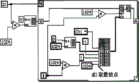
4.1软件解调系统设计4.1 Software demodulation system design
单通道(通道1)数据采集显示的LabVIEW程序图4所示。采样长度设为32KSa,DAQ-2005数据采集卡采样率为500KSps,FIFO读取以1KSa为单位,即每次只能读取1K个采样数据,所以必须通过32(32K/1K)次循环才能将数据全部读出。Figure 4 shows the LabVIEW program for the single-channel (channel 1) data acquisition display. The sampling length is set to 32KSa, the sampling rate of the DAQ-2005 data acquisition card is 500KSps, and the FIFO reading is in units of 1KSa, that is, only 1K sampling data can be read each time, so it must pass 32 (32K/1K) cycles to All data is read.
进一步的,程序基本流程:首先指定循环次数为32,并在循环体左侧部分,建立一个长度为32K的一维零数组作为初始数组送入读数循环;其次确定取数结点的外部参数,指定其每次读IKSample,指定采样通道为CH1,再利用循环体变量I(0〜31)在每次循环中移动1K单位的FIFO的读数指针,从而每次从取数结点读出IKSa个数据之后,循环按顺序替换对应位置的初始零数组,待全部循环完成之后,即得到32KSa的一维数据数组跳出循环;最后把数组的数据,0.1微秒的时间间隔(1/lOMHz,作为采样时间间隔)和起始的零时刻一同构成波形簇数据,送入波形窗waveform显示。Further, the basic flow of the program: first, specify the number of loops as 32, and in the left part of the loop body, create a one-dimensional zero array with a length of 32K as the initial array and send it to the reading loop; secondly, determine the external parameters of the fetching node, Specify it to read IKSample each time, specify the sampling channel as CH1, and then use the loop body variable I (0~31) to move the reading pointer of the 1K unit of FIFO in each loop, so as to read IKSa data from the fetch node each time After that, the loop replaces the initial zero array in the corresponding position in sequence, and after all the loops are completed, the one-dimensional data array of 32KSa is obtained and jumps out of the loop; finally, the data of the array, the time interval of 0.1 microseconds (1/10MHz, is used as the sampling time interval) and the initial zero time together form the waveform cluster data, and send it to the waveform window for display.
4.2.解调后信号处理4.2. Signal processing after demodulation
Fourier变换是信号分析领域应用最广泛地一种分析手段,但Fourier变换是一种纯频域的分析方法,它在频域的定位非常准确,但在时域无任何定位功能。然而大部分的振动信号其频域特性都是随时间而变化的,对这一类信号采用傅立叶变化进行分析,不能提供完全的信息,也即通过傅里叶变换可以知道信号所含有的频率信息,但并不能知道这些频率信息究竟出现在那些时间段上。为了研究信号在局部范围内的频率特性,1946年Garbor提出了加窗Fourier变换,基本思想是取时间函数g(t)作为窗口函数,用g(t-r)同待分析函数相乘,然后在进行Fourier变换,可以反映出一个信号在任意局部范围的频域特征。The Fourier transform is the most widely used analysis method in the field of signal analysis, but the Fourier transform is a pure frequency domain analysis method, and its positioning in the frequency domain is very accurate, but it does not have any positioning function in the time domain. However, the frequency domain characteristics of most vibration signals change with time. Using Fourier transform to analyze this type of signal cannot provide complete information, that is, the frequency information contained in the signal can be known through Fourier transform. , but it is not known in which time periods these frequency information appeared. In order to study the frequency characteristics of the signal in the local range, Garbor proposed the windowed Fourier transform in 1946. The basic idea is to take the time function g(t) as the window function, multiply g(t-r) with the function to be analyzed, and then perform Fourier transform can reflect the frequency domain characteristics of a signal in any local range.
但是由于窗口傅立叶变换的时间-频率窗宽度是固定不变的,虽然可以选择不同类型的窗函数,或者调整窗函数的参数来选择时间-频率的宽度。但是一旦窗函数的类型及参数确定之后,唯一可以调整的就是平移量T,而变量只能改变窗沿时间轴的位置,不能改变时间-频窗的宽度,这对于分析时变信号是不利的。因为高频信号一般持续时间很短,而低频信号持续时间较长,期望对于高频信号采用小时窗,对于低频信号则采用大时窗进行分析。这种变时窗的要求与窗口傅立叶变换的固定时窗的特性是矛盾的,使得窗口Fourier变换不能适应许多复杂的信号分析和处理。而且在对信号进行分析过程中,每次采样的时域信号两端都被截断,采用FFT算法计算频谱又会产生栅栏效应,为了解决这个问题,在本实施例中,系统根据业务特点,采用下面提到的算法。However, since the time-frequency window width of the window Fourier transform is fixed, although different types of window functions can be selected, or the parameters of the window function can be adjusted to select the time-frequency width. However, once the type and parameters of the window function are determined, the only thing that can be adjusted is the translation amount T, and the variable can only change the position of the window along the time axis, but not the width of the time-frequency window, which is unfavorable for analyzing time-varying signals. Because the high-frequency signal generally has a short duration, while the low-frequency signal has a long duration, it is desirable to use a small window for high-frequency signals and a large time window for low-frequency signals for analysis. The requirement of this variable time window is contradictory to the fixed time window characteristic of the windowed Fourier transform, which makes the windowed Fourier transform unable to adapt to many complex signal analysis and processing. Moreover, in the process of analyzing the signal, both ends of the time-domain signal sampled each time are truncated, and using the FFT algorithm to calculate the spectrum will produce a fence effect. In order to solve this problem, in this embodiment, the system adopts the The algorithm mentioned below.
4.3数据处理4.3 Data processing
在本实施例中,该系统采用到了下面的数据处理方法:In this embodiment, the system adopts the following data processing method:
两组信号做比值再相减:读取两组数据,对于每一组数据后项减前项再比上前一向的值,结果存放到前向的存储空间,再多次采样取平均。把两组处理后的数据相减。The ratio of the two sets of signals is then subtracted: read two sets of data, subtract the previous term for each set of data, and then compare the previous value, the result is stored in the forward memory space, and then sampled multiple times to average. Subtract the two sets of processed data.
这种方法用到了数据平均,是由于采用平均计算的方法对滤除随机噪声有很好的效果,能降低系统的噪声,提高系统的信噪比。如果对数据平均n次,信噪比就会提高n1/2倍,平均时间越长,动态范围就越大,信噪比改善越大,但超过一定的测量时间对信噪比的改善就不会再很明显了,所以测试时间一般控制在3分钟以内。This method uses data averaging, because the average calculation method has a good effect on filtering out random noise, which can reduce the noise of the system and improve the signal-to-noise ratio of the system. If the data is averaged n times, the signal-to-noise ratio will increase by n 1/2 times. The longer the averaging time, the larger the dynamic range and the greater the improvement of the signal-to-noise ratio, but the improvement of the signal-to-noise ratio exceeds a certain measurement time. It will not be obvious anymore, so the test time is generally controlled within 3 minutes.
5.传感器加工工艺5. Sensor processing technology
在本实施例中,用作光纤振动传感单元的光纤耦合器制作过程跟普通单模耦合器的制作过程相类似,将两根相同的单模光纤中部长约30mm的涂覆层剥去,清洗干净,平行置于熔融拉锥机中,如图5所示,放在高温下进行加热熔融,同时通过夹具向光纤的两端拉伸,当拉伸达到一定长度,两光纤之间就会发生能量的交换,最终在光纤的加热区形成双锥形式的特殊波导结构。In this embodiment, the manufacturing process of the optical fiber coupler used as the optical fiber vibration sensing unit is similar to the manufacturing process of the ordinary single-mode coupler. Clean it, put it in parallel in the melting taper machine, as shown in Figure 5, put it at high temperature for heating and melting, and at the same time stretch the two ends of the fiber through the clamp, when the stretching reaches a certain length, the two fibers will The exchange of energy occurs, and finally a biconical special waveguide structure is formed in the heating area of the fiber.
由于耦合器的参数如耦合比、附加损耗主要由双锥体的形状决定,而双锥体的形状主要由火焰形状、火焰移动范围、温度分布和拉伸速度来控制。在器件制作中必须优化设计和精确控制上述条件,获得最佳耦合长度、耦合横截面结构和能量转换周期等参数,设计不同的传感器封装结构,保证器件具有较高的灵敏度和较好的频谱响应。Since the parameters of the coupler such as coupling ratio, additional loss are mainly determined by the shape of the double cone, which is mainly controlled by the flame shape, flame moving range, temperature distribution and stretching speed. In the fabrication of the device, it is necessary to optimize the design and precisely control the above conditions to obtain parameters such as the optimal coupling length, coupling cross-sectional structure and energy conversion period, and design different sensor packaging structures to ensure that the device has higher sensitivity and better spectral response. .
以上是本发明的较佳实施例,凡依本发明技术方案所作的改变,所产生的功能作用未超出本发明技术方案的范围时,均属于本发明的保护范围。The above are the preferred embodiments of the present invention, all changes made according to the technical solutions of the present invention, when the resulting functional effects do not exceed the scope of the technical solutions of the present invention, belong to the protection scope of the present invention.
Claims (7)
Priority Applications (1)
| Application Number | Priority Date | Filing Date | Title |
|---|---|---|---|
| CN201710163237.5A CN106932083B (en) | 2017-03-19 | 2017-03-19 | Optical fiber wireless vibration sensor device based on high-intensity magnetic field background |
Applications Claiming Priority (1)
| Application Number | Priority Date | Filing Date | Title |
|---|---|---|---|
| CN201710163237.5A CN106932083B (en) | 2017-03-19 | 2017-03-19 | Optical fiber wireless vibration sensor device based on high-intensity magnetic field background |
Publications (2)
| Publication Number | Publication Date |
|---|---|
| CN106932083A CN106932083A (en) | 2017-07-07 |
| CN106932083B true CN106932083B (en) | 2020-09-04 |
Family
ID=59433705
Family Applications (1)
| Application Number | Title | Priority Date | Filing Date |
|---|---|---|---|
| CN201710163237.5A Active CN106932083B (en) | 2017-03-19 | 2017-03-19 | Optical fiber wireless vibration sensor device based on high-intensity magnetic field background |
Country Status (1)
| Country | Link |
|---|---|
| CN (1) | CN106932083B (en) |
Cited By (1)
| Publication number | Priority date | Publication date | Assignee | Title |
|---|---|---|---|---|
| CN112162228A (en) * | 2020-09-14 | 2021-01-01 | 国网江苏省电力有限公司电力科学研究院 | Fault early warning system suitable for optical fiber current sensor |
Families Citing this family (3)
| Publication number | Priority date | Publication date | Assignee | Title |
|---|---|---|---|---|
| CN110146775B (en) * | 2019-06-25 | 2021-07-09 | 广东石油化工学院 | Method and system for vibration-acoustic detection of transformer operating state based on power ratio |
| CN111442827B (en) * | 2020-04-08 | 2022-07-19 | 南京艾森斯智能科技有限公司 | Optical fiber passive online monitoring system for transformer winding vibration |
| CN111896894A (en) * | 2020-07-15 | 2020-11-06 | 太原理工大学 | An embedded optical fiber detection device for transformer windings |
Citations (7)
| Publication number | Priority date | Publication date | Assignee | Title |
|---|---|---|---|---|
| JP2008157759A (en) * | 2006-12-25 | 2008-07-10 | Sun Tec Kk | Optical fiber sensor system |
| CN101639379A (en) * | 2009-08-26 | 2010-02-03 | 南京大学 | Vibration monitoring structure and method based on optical fiber polarized light time domain reflection sensing |
| CN102168953A (en) * | 2011-01-12 | 2011-08-31 | 南京大学 | Full-distributed optical fiber strain and vibration sensor based on coherent heterodyne detection |
| CN202533198U (en) * | 2012-03-26 | 2012-11-14 | 湖北擎宇科技有限公司 | Distributed fiber Brillouinstrain strain and temperature sensor |
| CN102865914A (en) * | 2012-09-19 | 2013-01-09 | 朱涛 | Distributed optic fiber vibrating sensor |
| CN103017886A (en) * | 2012-12-03 | 2013-04-03 | 暨南大学 | Polarization-maintaining fiber grating two-dimensional vector vibration sensor |
| CN204931633U (en) * | 2015-07-27 | 2016-01-06 | 浙江大学 | Based on the frequency sweep OCT digit phase correction system of static region information |
-
2017
- 2017-03-19 CN CN201710163237.5A patent/CN106932083B/en active Active
Patent Citations (7)
| Publication number | Priority date | Publication date | Assignee | Title |
|---|---|---|---|---|
| JP2008157759A (en) * | 2006-12-25 | 2008-07-10 | Sun Tec Kk | Optical fiber sensor system |
| CN101639379A (en) * | 2009-08-26 | 2010-02-03 | 南京大学 | Vibration monitoring structure and method based on optical fiber polarized light time domain reflection sensing |
| CN102168953A (en) * | 2011-01-12 | 2011-08-31 | 南京大学 | Full-distributed optical fiber strain and vibration sensor based on coherent heterodyne detection |
| CN202533198U (en) * | 2012-03-26 | 2012-11-14 | 湖北擎宇科技有限公司 | Distributed fiber Brillouinstrain strain and temperature sensor |
| CN102865914A (en) * | 2012-09-19 | 2013-01-09 | 朱涛 | Distributed optic fiber vibrating sensor |
| CN103017886A (en) * | 2012-12-03 | 2013-04-03 | 暨南大学 | Polarization-maintaining fiber grating two-dimensional vector vibration sensor |
| CN204931633U (en) * | 2015-07-27 | 2016-01-06 | 浙江大学 | Based on the frequency sweep OCT digit phase correction system of static region information |
Cited By (2)
| Publication number | Priority date | Publication date | Assignee | Title |
|---|---|---|---|---|
| CN112162228A (en) * | 2020-09-14 | 2021-01-01 | 国网江苏省电力有限公司电力科学研究院 | Fault early warning system suitable for optical fiber current sensor |
| CN112162228B (en) * | 2020-09-14 | 2021-08-27 | 国网江苏省电力有限公司电力科学研究院 | Fault early warning system suitable for optical fiber current sensor |
Also Published As
| Publication number | Publication date |
|---|---|
| CN106932083A (en) | 2017-07-07 |
Similar Documents
| Publication | Publication Date | Title |
|---|---|---|
| CN102147236B (en) | Fully distributed optical fiber strain and vibration sensing method and sensor | |
| CN102538985B (en) | Sensing signal detection device and method based on fiber optic Brillouin ring laser | |
| CN106768277B (en) | A demodulation method for a distributed optical fiber vibration sensing device | |
| CN103743553B (en) | The dual channel optical performance testing device of a kind of integrated waveguide manipulator and polarization crosstalk identification thereof and processing method | |
| CN102168953A (en) | Full-distributed optical fiber strain and vibration sensor based on coherent heterodyne detection | |
| CN115452015B (en) | Phase noise accurate correction optical frequency domain reflectometer for double-scale reference interference | |
| WO2023001158A1 (en) | Optical frequency domain interference-based distributed bidirectional polarization measurement apparatus for optical fiber device | |
| CN103940588B (en) | The suppressing method of the polarization decay restraining device that optically-based cross polarization is measured | |
| CN106248247A (en) | A kind of based on the brillouin distributed temperature of Raman, the sensing device of the double Parametric Detection of stress | |
| CN105043718A (en) | Noise suppression device and noise suppression method for distributed polarization crosstalk measurement of optical polarizer | |
| CN103900680A (en) | Device and detecting method for restraining polarization crosstalk measuring noise by the adoption of light source | |
| CN106932083A (en) | A kind of optical-fiber wireless vibrating sensor device based on high-intensity magnetic field background | |
| CN109991511B (en) | Lightning stroke monitoring device and monitoring method for overhead line | |
| CN103900799B (en) | A kind of optical coherence polarimeter that suppresses interaction noise | |
| CN102928740B (en) | Intelligent collection type fault diagnosis and In-Line Temperature Measure System | |
| CN104280217A (en) | Dual-channel optical performance measuring device for Y waveguide | |
| CN106153089A (en) | A kind of distributed optical fiber sensing system | |
| CN113252089A (en) | Distributed optical fiber sensing device | |
| CN107436201A (en) | Distributed fiber optic temperature strain sensing system and method based on Brillouin scattering | |
| CN110768714B (en) | Polarized light time domain reflectometer based on dual-polarization state time division multiplexing and detection method | |
| CN104280215A (en) | Dual-channel optical performance bi-directional multi-alignment-angle automatic testing device for Y waveguide | |
| CN107167225A (en) | A kind of distributed optical fiber stress and the sensor-based system and its method for sensing of vibration | |
| CN211740563U (en) | Optical time domain reflectometer | |
| CN112880865B (en) | Ultra-long-distance high-spatial-resolution Raman optical fiber dual-parameter sensing system and method | |
| CN203572631U (en) | Optical time-domain reflectometer based on superconducting nanowire single-photon detector |
Legal Events
| Date | Code | Title | Description |
|---|---|---|---|
| PB01 | Publication | ||
| PB01 | Publication | ||
| SE01 | Entry into force of request for substantive examination | ||
| SE01 | Entry into force of request for substantive examination | ||
| GR01 | Patent grant | ||
| GR01 | Patent grant |