CN106935962B - Terminal device and antenna - Google Patents
Terminal device and antenna Download PDFInfo
- Publication number
- CN106935962B CN106935962B CN201511023172.1A CN201511023172A CN106935962B CN 106935962 B CN106935962 B CN 106935962B CN 201511023172 A CN201511023172 A CN 201511023172A CN 106935962 B CN106935962 B CN 106935962B
- Authority
- CN
- China
- Prior art keywords
- antenna
- terminal device
- body part
- antennas
- arm
- Prior art date
- Legal status (The legal status is an assumption and is not a legal conclusion. Google has not performed a legal analysis and makes no representation as to the accuracy of the status listed.)
- Active
Links
Images


Classifications
-
- H—ELECTRICITY
- H01—ELECTRIC ELEMENTS
- H01Q—ANTENNAS, i.e. RADIO AERIALS
- H01Q13/00—Waveguide horns or mouths; Slot antennas; Leaky-waveguide antennas; Equivalent structures causing radiation along the transmission path of a guided wave
- H01Q13/10—Resonant slot antennas
-
- H—ELECTRICITY
- H01—ELECTRIC ELEMENTS
- H01Q—ANTENNAS, i.e. RADIO AERIALS
- H01Q1/00—Details of, or arrangements associated with, antennas
- H01Q1/36—Structural form of radiating elements, e.g. cone, spiral, umbrella; Particular materials used therewith
-
- H—ELECTRICITY
- H01—ELECTRIC ELEMENTS
- H01Q—ANTENNAS, i.e. RADIO AERIALS
- H01Q1/00—Details of, or arrangements associated with, antennas
- H01Q1/12—Supports; Mounting means
- H01Q1/22—Supports; Mounting means by structural association with other equipment or articles
-
- H—ELECTRICITY
- H01—ELECTRIC ELEMENTS
- H01Q—ANTENNAS, i.e. RADIO AERIALS
- H01Q1/00—Details of, or arrangements associated with, antennas
- H01Q1/44—Details of, or arrangements associated with, antennas using equipment having another main function to serve additionally as an antenna, e.g. means for giving an antenna an aesthetic aspect
-
- H—ELECTRICITY
- H01—ELECTRIC ELEMENTS
- H01Q—ANTENNAS, i.e. RADIO AERIALS
- H01Q1/00—Details of, or arrangements associated with, antennas
- H01Q1/50—Structural association of antennas with earthing switches, lead-in devices or lightning protectors
-
- H—ELECTRICITY
- H01—ELECTRIC ELEMENTS
- H01Q—ANTENNAS, i.e. RADIO AERIALS
- H01Q21/00—Antenna arrays or systems
Landscapes
- Support Of Aerials (AREA)
Abstract
本发明公开了一种终端设备及天线,应用于通信技术领域,为了解决现有技术中存在的应用在终端设备中的天线系统占用终端设备较大内部空间的问题而发明。该终端设备,包括预设数量的天线,预设数量的天线位于终端设备的边缘,所述天线包括第一天线臂和第二天线臂;第一天线臂包括第一本体部分和第一弯折部分,第二天线臂包括第二本体部分和第二弯折部分,第一本体部分和第一弯折部分互相垂直,第二本体部分和第二弯折部分互相垂直;第一本体部分和第二本体部分之间的空间形成天线的馈电端,天线的馈电端用于输入平衡馈电信号。本发明应用在终端设备的制造过程中。
The invention discloses a terminal device and an antenna, which are applied in the field of communication technology and are invented to solve the problem that the antenna system applied in the terminal device occupies a large internal space of the terminal device in the prior art. The terminal device includes a preset number of antennas, the preset number of antennas are located at the edge of the terminal device, the antenna includes a first antenna arm and a second antenna arm; the first antenna arm includes a first body part and a first bend part, the second antenna arm includes a second body part and a second bending part, the first body part and the first bending part are perpendicular to each other, the second body part and the second bending part are perpendicular to each other; the first body part and the first bending part are perpendicular to each other; The space between the two body parts forms the feed end of the antenna, and the feed end of the antenna is used to input the balanced feed signal. The present invention is applied in the manufacturing process of terminal equipment.
Description
技术领域technical field
本发明涉及通信技术领域,尤其涉及一种终端设备及天线。The present invention relates to the field of communication technologies, and in particular, to a terminal device and an antenna.
背景技术Background technique
目前,手机等终端设备一般包括一个或多个用于收发信号的内置天线。平面倒F型天线(Planar Inverted-F Antenna,PIFA)为应用于终端设备中的一种常见的内置天线。At present, terminal devices such as mobile phones generally include one or more built-in antennas for transmitting and receiving signals. A Planar Inverted-F Antenna (PIFA) is a common built-in antenna used in terminal equipment.
多输入多输出(Multiple-Input Multiple-Output,MIMO)技术,是指在发射端和接收端分别使用多个发射天线和接收天线,使信号通过发射端与接收端的多个天线传送和接收,从而提高通信系统的吞吐量。Multiple-Input Multiple-Output (MIMO) technology refers to the use of multiple transmitting and receiving antennas at the transmitting end and the receiving end, respectively, so that signals are transmitted and received through multiple antennas at the transmitting and receiving ends. Improve the throughput of the communication system.
采用MIMO技术后,手机等终端设备常用的天线系统如图1所示。终端设备的边缘集成多个平面倒F型天线(Planar Inverted-F Antenna,PIFA)101,多个PIFA共用一块地板102。After adopting MIMO technology, the commonly used antenna system of terminal equipment such as mobile phone is shown in Figure 1. A plurality of Planar Inverted-F Antennas (PIFAs) 101 are integrated on the edge of the terminal device, and the plurality of PIFAs share a
但是,单个PIFA天线占用的终端设备的空间较大,应用MIMO技术后,终端设备中的天线的数量较多,则天线系统占用的终端设备的内部空间较大。However, a single PIFA antenna occupies a large space of the terminal device. After the MIMO technology is applied, the number of antennas in the terminal device is large, and the internal space of the terminal device occupied by the antenna system is large.
发明内容SUMMARY OF THE INVENTION
本发明提供一种终端设备及天线,以解决现有技术中存在的天线占用的终端设备的内部空间较大的问题。The present invention provides a terminal device and an antenna to solve the problem in the prior art that the internal space of the terminal device occupied by the antenna is large.
为达到上述目的,本发明采用如下技术方案:To achieve the above object, the present invention adopts the following technical solutions:
第一方面,本发明提供一种终端设备,包括预设数量的天线,所述预设数量的天线位于所述终端设备的边缘,所述天线包括第一天线臂和第二天线臂;所述第一天线臂包括第一本体部分和第一弯折部分,所述第二天线臂包括第二本体部分和第二弯折部分,所述第一本体部分和第一弯折部分互相垂直,所述第二本体部分和第二弯折部分互相垂直;所述第一本体部分和所述第二本体部分之间的空间形成所述天线的馈电端,所述天线的馈电端用于输入平衡馈电信号。本发明提供的终端设备采用了一种不同于现有技术中的天线的新型天线,这种新型天线的两个天线臂均包括弯折部分和本体部分,弯折部分和本体部分相互垂直,相当于将天线臂的一部分进行了“弯折”,能够减小天线臂的高度,使得这种新型天线能够应用在终端设备的边缘,减小对终端设备内部空间的占用。In a first aspect, the present invention provides a terminal device, comprising a preset number of antennas, the preset number of antennas being located at the edge of the terminal device, and the antennas include a first antenna arm and a second antenna arm; the The first antenna arm includes a first body part and a first bending part, the second antenna arm includes a second body part and a second bending part, and the first body part and the first bending part are perpendicular to each other, so The second body part and the second bending part are perpendicular to each other; the space between the first body part and the second body part forms the feed end of the antenna, and the feed end of the antenna is used for input Balanced feed signal. The terminal device provided by the present invention adopts a new type of antenna which is different from the antenna in the prior art. The two antenna arms of this new type of antenna both include a bent part and a body part, and the bent part and the body part are perpendicular to each other, which is quite Because a part of the antenna arm is "bent", the height of the antenna arm can be reduced, so that this new type of antenna can be applied to the edge of the terminal device and reduce the occupation of the internal space of the terminal device.
结合第一方面,在第一方面的第一种实现方式中,当所述预设数量大于等于2时,相邻天线径向排列。在该实现方式中,本发明提供的天线采用平衡馈电信号馈电,使得这种新型天线沿天线径向辐射的能量比较小,当终端设备中包括多个这种新型天线时,将相邻天线径向排列,能够减少相邻天线之间的耦合,进而无需增加去耦设计,其实现较为简单。With reference to the first aspect, in a first implementation manner of the first aspect, when the preset number is greater than or equal to 2, adjacent antennas are radially arranged. In this implementation manner, the antenna provided by the present invention is fed by a balanced feed signal, so that the energy radiated by this new type of antenna along the radial direction of the antenna is relatively small. The radial arrangement of the antennas can reduce the coupling between adjacent antennas, so that there is no need to increase the decoupling design, and the implementation is relatively simple.
结合第一方面,在第一方面的第二种实现方式中,所述天线还包括连接片,所述第一弯折部分和所述第二弯折部分通过所述连接片互相连接。在该实现方式中,将天线的两个天线臂的弯折部分连接后,能够提高天线的收发信号的质量。With reference to the first aspect, in a second implementation manner of the first aspect, the antenna further includes a connecting piece, and the first bending portion and the second bending portion are connected to each other through the connecting piece. In this implementation manner, after the bent portions of the two antenna arms of the antenna are connected, the quality of the transmitted and received signals of the antenna can be improved.
结合第一方面,在第一方面的第三种实现方式中,当所述终端设备的边框为金属边框且所述金属边框上设置有缝隙时,所述天线的第一本体部分和第二本体部分分别为所述缝隙两侧的金属边框,所述天线的馈电端为所述缝隙。在该实现方式中,利用终端设备的边框来制作天线,能够充分利用终端设备的边框,节约天线的制作成本以及占用空间。With reference to the first aspect, in a third implementation manner of the first aspect, when the frame of the terminal device is a metal frame and the metal frame is provided with a slit, the first body part and the second body of the antenna are The parts are respectively the metal frames on both sides of the slot, and the feed end of the antenna is the slot. In this implementation manner, the frame of the terminal device is used to manufacture the antenna, so that the frame of the terminal device can be fully utilized, and the fabrication cost and space occupied of the antenna can be saved.
结合第一方面,在第一方面的第四种实现方式中,当所述终端设备的边框为非金属边框时,所述预设数量的天线位于所述非金属边框的内侧。With reference to the first aspect, in a fourth implementation manner of the first aspect, when the frame of the terminal device is a non-metal frame, the preset number of antennas are located inside the non-metal frame.
结合第一方面,在第一方面的第五种实现方式中,当所述预设数量大于等于2时,相邻天线相距0.4~0.6个波长。在该实现方式中,将相邻天线之间的距离设置为0.4~0.6个波长,能够使得天线的摆放更为紧凑,有利于提高终端设备的边缘部分的空间利用率。With reference to the first aspect, in a fifth implementation manner of the first aspect, when the preset number is greater than or equal to 2, adjacent antennas are separated by 0.4-0.6 wavelengths. In this implementation manner, the distance between adjacent antennas is set to 0.4-0.6 wavelengths, which can make the placement of the antennas more compact, which is beneficial to improve the space utilization rate of the edge portion of the terminal device.
结合第一方面,在第一方面的第六种实现方式中,所述预设数量为2~8个。With reference to the first aspect, in a sixth implementation manner of the first aspect, the preset number is 2-8.
第二方面,本发明提供一种天线,包括第一天线臂和第二天线臂;所述第一天线臂包括第一本体部分和第一弯折部分,所述第二天线臂包括第二本体部分和第二弯折部分,所述第一本体部分和第一弯折部分互相垂直,所述第二本体部分和第二弯折部分互相垂直;所述第一本体部分和所述第二本体部分之间的空间形成所述天线的馈电端,所述天线的馈电端用于输入平衡馈电信号。本发明提供的这种新型天线,其两个天线臂均包括弯折部分和本体部分,弯折部分和本体部分相互垂直,相当于将天线臂的一部分进行了“弯折”,能够减小天线臂的高度,使得这种新型天线能够应用在终端设备的边缘,减小对终端设备内部空间的占用。In a second aspect, the present invention provides an antenna including a first antenna arm and a second antenna arm; the first antenna arm includes a first body portion and a first bent portion, and the second antenna arm includes a second body part and a second bending part, the first body part and the first bending part are perpendicular to each other, the second body part and the second bending part are perpendicular to each other; the first body part and the second body The space between the parts forms the feed end of the antenna, and the feed end of the antenna is used for inputting a balanced feed signal. In the novel antenna provided by the present invention, the two antenna arms of the antenna both include a bent part and a body part, and the bent part and the body part are perpendicular to each other, which is equivalent to "bending" a part of the antenna arm, which can reduce the size of the antenna. The height of the arm enables this new type of antenna to be applied to the edge of the terminal device, reducing the occupation of the internal space of the terminal device.
结合第二方面,在第二方面的第一种实现方式中,所述天线还包括连接片,所述第一弯折部分和所述第二弯折部分通过所述连接片互相连接。在该实现方式中,将天线的两个天线臂的弯折部分连接后,能够提高天线的收发信号的质量。With reference to the second aspect, in a first implementation manner of the second aspect, the antenna further includes a connecting piece, and the first bending portion and the second bending portion are connected to each other through the connecting piece. In this implementation manner, after the bent portions of the two antenna arms of the antenna are connected, the quality of the transmitted and received signals of the antenna can be improved.
结合第二方面,在第二方面的第二种实现方式中,所述天线的馈电端与平衡信号馈电器连接。该实现方式提供了一种采用平衡信号馈电器直接为天线馈电的馈电方式。With reference to the second aspect, in a second implementation manner of the second aspect, a feed end of the antenna is connected to a balanced signal feeder. This implementation provides a feeding method in which a balanced signal feeder is used to directly feed the antenna.
结合第二方面,在第二方面的第三种实现方式中,所述天线的馈电端与非平衡信号转换模块连接,所述非平衡信号转换模块与非平衡信号馈电器连接。该实现方式提供了将非平衡信号馈电器提供的非平衡信号通过非平衡信号转换模块转换为平衡信号的间接馈电方式。With reference to the second aspect, in a third implementation manner of the second aspect, a feed end of the antenna is connected to an unbalanced signal conversion module, and the unbalanced signal conversion module is connected to an unbalanced signal feeder. This implementation provides an indirect feeding method in which the unbalanced signal provided by the unbalanced signal feeder is converted into a balanced signal through the unbalanced signal conversion module.
结合第二方面,在第二方面的第四种实现方式中,所述第一弯折部分占所述第一天线臂的总长度的10%~90%。所述第二弯折部分占所述第二天线臂的总长度的10%~90%。With reference to the second aspect, in a fourth implementation manner of the second aspect, the first bent portion accounts for 10% to 90% of the total length of the first antenna arm. The second bent portion accounts for 10%-90% of the total length of the second antenna arm.
本发明提供了一种终端设备和天线,其中,该天线的两个天线臂均包括弯折部分和本体部分,弯折部分和本体部分相互垂直,相当于将天线臂的一部分进行了“弯折”,能够减小天线臂的高度,使得这种新型天线能够应用在终端设备的边缘,减小对终端设备内部空间的占用。The present invention provides a terminal device and an antenna, wherein the two antenna arms of the antenna both include a bent part and a body part, and the bent part and the body part are perpendicular to each other, which is equivalent to "bending a part of the antenna arm" ”, which can reduce the height of the antenna arm, so that this new type of antenna can be applied to the edge of the terminal device and reduce the occupation of the internal space of the terminal device.
附图说明Description of drawings
为了更清楚地说明本发明实施例或现有技术中的技术方案,下面将对实施例或现有技术描述中所需要使用的附图作简单地介绍,显而易见地,下面描述中的附图仅仅是本发明的一些实施例,对于本领域普通技术人员来讲,在不付出创造性劳动的前提下,还可以根据这些附图获得其他的附图。In order to explain the embodiments of the present invention or the technical solutions in the prior art more clearly, the following briefly introduces the accompanying drawings that need to be used in the description of the embodiments or the prior art. Obviously, the accompanying drawings in the following description are only These are some embodiments of the present invention. For those of ordinary skill in the art, other drawings can also be obtained according to these drawings without creative efforts.
图1为现有技术中提供的天线系统的结构示意图;1 is a schematic structural diagram of an antenna system provided in the prior art;
图2为本发明实施例提供的一种天线的结构示意图;FIG. 2 is a schematic structural diagram of an antenna according to an embodiment of the present invention;
图3为本发明实施例提供的另一种天线的结构示意图;FIG. 3 is a schematic structural diagram of another antenna provided by an embodiment of the present invention;
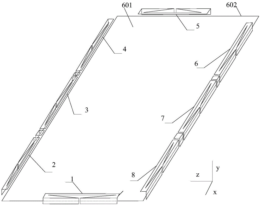
图4为本发明实施例提供的一种终端设备的结构示意图;FIG. 4 is a schematic structural diagram of a terminal device according to an embodiment of the present invention;
图5-1、图5-2为本发明实施例提供的图4所示的天线2的辐射方向示意图;5-1 and 5-2 are schematic diagrams of radiation directions of the
图6-1、图6-2为本发明实施例提供的图4所示的天线3的辐射方向示意图;6-1 and 6-2 are schematic diagrams of radiation directions of the
图7为本发明实施例提供的图4所示的天线系统的仿真散射参数示意图。FIG. 7 is a schematic diagram of simulated scattering parameters of the antenna system shown in FIG. 4 according to an embodiment of the present invention.
具体实施方式Detailed ways
下面将结合本实施例中的附图,对本实施例中的技术方案进行清楚、完整地描述,显然,所描述的实施例仅仅是本发明一部分实施例,而不是全部的实施例。基于本发明中的实施例,本领域普通技术人员在没有作出创造性劳动前提下所获得的所有其他实施例,都属于本发明保护的范围。The technical solutions in this embodiment will be clearly and completely described below with reference to the drawings in this embodiment. Obviously, the described embodiments are only a part of the embodiments of the present invention, but not all of the embodiments. Based on the embodiments of the present invention, all other embodiments obtained by those of ordinary skill in the art without creative efforts shall fall within the protection scope of the present invention.
本发明实施例提供一种天线,如图2所示,该天线包括第一天线臂20和第二天线臂30;所述第一天线臂20包括第一本体部分201和第一弯折部分202,所述第二天线臂30包括第二本体部分301和第二弯折部分302。其中,所述第一本体部分201和第一弯折部分202互相垂直,所述第二本体部分301和第二弯折部分302互相垂直;所述第一本体部分201和所述第二本体部分301之间的空间形成所述天线的馈电端40,所述天线的馈电端40用于输入平衡馈电信号。An embodiment of the present invention provides an antenna. As shown in FIG. 2 , the antenna includes a
其中,本发明实施例提供的上述天线主要应用于终端设备。本发明实施例所指的终端设备包括手机、电脑、平板电脑等任意主要通过天线实现通信的电子设备。The above-mentioned antenna provided in the embodiment of the present invention is mainly applied to terminal equipment. The terminal device referred to in the embodiments of the present invention includes any electronic device that mainly implements communication through an antenna, such as a mobile phone, a computer, and a tablet computer.
其中,在将本发明实施例提供的天线应用在终端设备的过程中,两个天线臂的弯折部分和本体部分的长度可根据终端设备的厚度等实际需要设定,例如:当天线臂总体长度较长,而终端设备的厚度较小时,可将天线臂中超出终端设备厚度的部分进行弯折,形成天线臂的弯折部分,使得天线能够应用在终端设备中。可选的,第一天线臂中,所述第一弯折部分占所述第一天线臂的总长度的10%~90%;第二天线臂中,所述第二弯折部分占所述第二天线臂的总长度的10%~90%。Wherein, in the process of applying the antenna provided by the embodiment of the present invention to a terminal device, the lengths of the bent part and the body part of the two antenna arms can be set according to actual needs such as the thickness of the terminal device. When the length is long and the thickness of the terminal device is small, the part of the antenna arm that exceeds the thickness of the terminal device can be bent to form a bent part of the antenna arm, so that the antenna can be used in the terminal device. Optionally, in the first antenna arm, the first bent portion accounts for 10% to 90% of the total length of the first antenna arm; in the second antenna arm, the second bent portion accounts for the 10% to 90% of the total length of the second antenna arm.
其中,本发明实施例提供的上述天线采用平衡馈电信号实现馈电,在该具体实现过程中,作为一种可选的馈电方式,天线的馈电端与平衡信号馈电器连接,使得平衡信号馈电器产生的平衡馈电信号直接为天线馈电。作为另一种可选的馈电方式,所述天线的馈电端与非平衡信号转换模块连接,所述非平衡信号转换模块与非平衡信号馈电器连接,使得非平衡信号馈电器产生的非平衡信号经非平衡信号转换模块转换为平衡信号后为天线馈电。例如:该非平衡信号馈电器可以为同轴线,该非平衡信号转换模块可以为巴伦。当采用同轴线给天线馈电时,由于同轴线提供非平衡信号,线缆的外层也会参与辐射,会影响天线的辐射方向,因而可以在天线的馈电端和同轴线之间增加一个巴伦,将同轴线提供的非平衡信号转换成平衡信号对天线进行馈电。The above-mentioned antenna provided in the embodiment of the present invention uses a balanced feed signal to realize power feeding. In the specific implementation process, as an optional feeding mode, the feeding end of the antenna is connected to the balanced signal feeder, so that the balanced signal feeder is connected to the antenna. The balanced feed signal produced by the signal feeder directly feeds the antenna. As another optional feeding method, the feeding end of the antenna is connected to an unbalanced signal conversion module, and the unbalanced signal conversion module is connected to an unbalanced signal feeder, so that the unbalanced signal generated by the unbalanced signal feeder is The balanced signal is converted into a balanced signal by the unbalanced signal conversion module and then feeds the antenna. For example, the unbalanced signal feeder may be a coaxial line, and the unbalanced signal conversion module may be a balun. When the coaxial cable is used to feed the antenna, since the coaxial cable provides an unbalanced signal, the outer layer of the cable will also participate in the radiation, which will affect the radiation direction of the antenna. A balun is added in between to convert the unbalanced signal provided by the coaxial line into a balanced signal to feed the antenna.
为了提高天线的收发信号的性能,可在图2所示的天线中增加一个连接片结构,将天线的两个天线臂的弯折部分连接。因此,可选的,如图3所示,所述天线还包括连接片50,所述第一弯折部分202和所述第二弯折部分302通过所述连接片50互相连接。In order to improve the performance of the antenna for sending and receiving signals, a connecting sheet structure may be added to the antenna shown in FIG. 2 to connect the bent portions of the two antenna arms of the antenna. Therefore, optionally, as shown in FIG. 3 , the antenna further includes a connecting
本发明实施例提供的天线,其两个天线臂均包括弯折部分和本体部分,且弯折部分和本体部分相互垂直,相当于将天线臂的一部分进行了“弯折”,能够减小天线臂的高度,与现有技术中PIFA天线需要占用较多的终端设备内部空间相比,本发明实施例提供的天线能够应用在终端设备的边缘,减小对终端设备的内部空间的占用。In the antenna provided by the embodiment of the present invention, both antenna arms of the antenna include a bent part and a body part, and the bent part and the body part are perpendicular to each other, which is equivalent to "bending" a part of the antenna arm, which can reduce the size of the antenna. The height of the arm, compared with the prior art PIFA antenna needs to occupy more internal space of the terminal device, the antenna provided by the embodiment of the present invention can be applied to the edge of the terminal device, reducing the occupation of the internal space of the terminal device.
另外,现有技术中,应用于终端设备上的PIFA天线等天线普遍采用非平衡信号馈电,容易在相邻天线之间产生强烈的耦合,需要增加专门的去耦结构或去耦网格,其实现较为复杂。本发明提供的这种天线采用平衡馈电信号馈电,使得这种天线沿天线径向辐射的能量比较小,当终端设备中包括多个这种新型天线时,能够减少相邻天线之间的耦合,进而无需增加去耦设计,其实现较为简单。In addition, in the prior art, antennas such as PIFA antennas applied to terminal equipment generally use unbalanced signal feeding, which is prone to strong coupling between adjacent antennas, and needs to add special decoupling structures or decoupling grids. Its implementation is more complicated. The antenna provided by the present invention is fed by a balanced feed signal, so that the energy radiated by the antenna along the radial direction of the antenna is relatively small, and when the terminal device includes a plurality of such new antennas, the interference between adjacent antennas can be reduced. Coupling, and no need to add decoupling design, its implementation is relatively simple.
将本发明实施例提供的天线应用到终端设备中,本发明实施例还提供了一种终端设备,包括预设数量的天线,所述预设数量的天线位于所述终端设备的边缘。By applying the antenna provided by the embodiment of the present invention to a terminal device, the embodiment of the present invention further provides a terminal device, including a preset number of antennas, and the preset number of antennas are located at the edge of the terminal device.
其中,该终端设备中包括的天线的具体实现方式可参考前文所述,此处不再赘述。For the specific implementation of the antenna included in the terminal device, reference may be made to the foregoing description, which will not be repeated here.
为了保证天线系统的有效工作,可将所述预设数量的天线设置在所述终端设备的侧壁、边框、后盖边缘等终端设备的边缘部分。In order to ensure the effective operation of the antenna system, the preset number of antennas may be arranged on the edge portion of the terminal device such as the side wall, frame, and edge of the back cover of the terminal device.
其中,所述预设数量的取值可以为任意值;既可以为1个也可以为多个。具体而言,终端设备中天线个数,可根据终端设备的天线系统的设计需求,如天线系统的工作频率以及终端设备的尺寸等确定,一般为2-8个。Wherein, the value of the preset number may be any value; it may be one or more than one. Specifically, the number of antennas in the terminal device can be determined according to the design requirements of the antenna system of the terminal device, such as the operating frequency of the antenna system and the size of the terminal device, and is generally 2-8.
示例性的,如图4所示,本发明实施例提供的终端设备,该终端设备包括介质基板601和边框602,以及分别位于上边框的天线1、位于下边框的天线5、位于左边框的天线2、天线3、天线4以及位于右边框的天线6、天线7和天线8这样8个天线。Exemplarily, as shown in FIG. 4 , in the terminal device provided by the embodiment of the present invention, the terminal device includes a
需要说明的是,图4中示出的介质基板601为终端设备中的结构,其具体实现可参考现有技术,本发明实施例不再赘述。It should be noted that the
可选的,由于沿天线径向辐射的能量较小,为了减小相邻天线之间的耦合,当所述预设数量大于等于2时,如图4所示,相邻天线径向排列。Optionally, since the energy radiated in the radial direction of the antenna is small, in order to reduce the coupling between adjacent antennas, when the preset number is greater than or equal to 2, as shown in FIG. 4 , the adjacent antennas are arranged radially.
可选的,为了充分利用终端设备的边框,节约天线的制作成本以及占用空间,当所述终端设备的边框为金属边框且所述金属边框上设置有缝隙时,所述天线的第一本体部分和第二本体部分分别为所述缝隙两侧的金属边框,所述天线的馈电端为所述缝隙;可分别增加与第一本体部分垂直的金属片形成第一弯折部分,增加与第二本体部分垂直的金属片形成第二弯折部分。当所述终端设备的边框为非金属边框时,所述预设数量的天线位于所述非金属边框的内侧。在实际制作过程中,当终端设备的边框为金属边框时,可在该金属边框上开设一些缝隙,使缝隙充当天线的馈电端,相邻天线之间的金属边框充当天线的天线臂的本体部分,然后根据需要增加天线的弯折部分。当终端设备的边框为非金属边框时,可将天线印刷在非金属边框的内侧。Optionally, in order to make full use of the frame of the terminal device and save the manufacturing cost and occupied space of the antenna, when the frame of the terminal device is a metal frame and a slot is provided on the metal frame, the first body part of the antenna is and the second body part are respectively the metal frame on both sides of the slot, and the feed end of the antenna is the slot; metal sheets perpendicular to the first body part can be respectively added to form a first bending part, and a The vertical metal sheets of the two body parts form the second bending part. When the frame of the terminal device is a non-metal frame, the preset number of antennas are located inside the non-metal frame. In the actual production process, when the frame of the terminal device is a metal frame, some slits can be opened on the metal frame, so that the slit acts as the feed end of the antenna, and the metal frame between adjacent antennas acts as the body of the antenna arm of the antenna. section, then add the bent section of the antenna as needed. When the frame of the terminal device is a non-metal frame, the antenna can be printed on the inner side of the non-metal frame.
可选的,当所述预设数量大于等于2时,可以适当设置相邻天线的距离,使得相邻天线相距0.4~0.6个波长。这样一方面能够实现天线之间的高隔离,进一步的减少天线之间的耦合,另一方面,能够使得天线的摆放更为紧凑,有利于提高终端设备的空间利用率。Optionally, when the preset number is greater than or equal to 2, the distance between adjacent antennas may be appropriately set so that the adjacent antennas are separated by 0.4-0.6 wavelengths. In this way, on the one hand, high isolation between the antennas can be achieved, which further reduces the coupling between the antennas;
本发明实施例提供的终端设备采用了一种不同于现有技术中的天线的新型天线,这种新型天线的两个天线臂均包括弯折部分和本体部分,弯折部分和本体部分相互垂直,相当于将天线臂的一部分进行了“弯折”,能够减小天线臂的高度,将这种天线应用在终端设备的边缘部分,能够减小对终端设备内部空间的占用。The terminal device provided by the embodiment of the present invention adopts a new type of antenna that is different from the antenna in the prior art. The two antenna arms of the new type of antenna both include a bent part and a body part, and the bent part and the body part are perpendicular to each other. , which is equivalent to "bending" a part of the antenna arm, which can reduce the height of the antenna arm. Applying this antenna to the edge part of the terminal device can reduce the occupation of the internal space of the terminal device.
另外,现有技术中的终端设备一般采用PIFA等采用非平衡信号馈电的天线,而本发明实施例提供的终端设备中的天线采用平衡信号馈电,这种采用平衡信号馈电的天线沿天线径向辐射的能量比较小,利用天线的这种辐射特性,能够减小相邻天线之间的耦合,因而,本发明提供的终端设备不需要添加任何去耦结构,其实现较简单。In addition, the terminal equipment in the prior art generally uses an antenna fed by an unbalanced signal, such as a PIFA, while the antenna in the terminal equipment provided by the embodiment of the present invention is fed with a balanced signal. The radial radiation energy of the antenna is relatively small, and the coupling between adjacent antennas can be reduced by using this radiation characteristic of the antenna. Therefore, the terminal device provided by the present invention does not need to add any decoupling structure, and its implementation is relatively simple.
为了更加清楚的解释上述效果,本发明实施例还提供了天线的辐射方向示意图。图5-1为图4所示终端设备中天线2在z-x平面的辐射方向示意图,图5-2为图4所示终端设备中天线2在z-y平面的辐射方向示意图,其中实线为主极化辐射方向示意图,虚线为交叉极化辐射方向示意图。图6-1为图4所示终端设备中天线3在z-x平面的辐射方向示意图,图6-2为图4所示终端设备中天线3在z-y平面的辐射方向示意图,同样的,实线为主极化辐射方向示意图,虚线为交叉极化辐射方向示意图。从图5-1、图5-2、图6-1、图6-2中可以看出,图4所示天线2和天线3主要向介质基板的外侧辐射,且在径向方向上的辐射能量较小,因此天线2和天线3之间的相互影响也比较小,天线之间的耦合也比较低。天线的最大增益约为2dBi,在主辐射方向上交叉极化小于-20dB,因此也表现出良好的线性极化特性。In order to explain the above effects more clearly, the embodiment of the present invention also provides a schematic diagram of the radiation direction of the antenna. Figure 5-1 is a schematic diagram of the radiation direction of the
需要说明的是,图6-2中仅以实线示出了主极化辐射方向图,而未示出虚线,表明天线系统的辐射方向主要集中在主极化辐射方向,交叉极化辐射方向的辐射几乎可忽略不计。It should be noted that, in Figure 6-2, only the main polarization radiation pattern is shown by the solid line, and the dashed line is not shown, indicating that the radiation direction of the antenna system is mainly concentrated in the main polarization radiation direction, and the cross-polarization radiation direction. radiation is almost negligible.
图7为图4所示的终端设备中的天线的仿真散射参数。图7中,横坐标表示频率,纵坐标表示散射参数的幅值。其中,|S(1,1)|表示天线1在不同频率下的回波损耗;|S(2,2)|表示天线2在不同频率下的回波损耗;|S(3,3)|表示天线3在不同频率下的回波损耗;|S(1,2)|表示天线1和天线2之间在不同频率下产生的互耦;|S(2,3)|表示天线2和天线3之间在不同频率下产生的互耦。从图7可以看出,由于天线1,天线2和天线3所处位置不同,因而它们的回波损耗略有差别,当回波损耗的值小于-6dB,便认为天线系统可正常工作;由图7可以看出,天线的工作频率为2.5至2.9GHz,-6dB阻抗带宽在16%左右,天线1和天线2之间的最大耦合约为-15dB,天线2和天线3之间的最大耦合约为-20dB,一般要求天线之间的互耦小于-10dB,因此以上参数均满足设计要求。FIG. 7 shows simulated scattering parameters of the antenna in the terminal device shown in FIG. 4 . In Fig. 7, the abscissa represents the frequency, and the ordinate represents the amplitude of the scattering parameter. where |S(1,1)| represents the return loss of antenna 1 at different frequencies; |S(2,2)| represents the return loss of
以上所述,仅为本发明的具体实施方式,但本发明的保护范围并不局限于此,任何熟悉本技术领域的技术人员在本发明揭露的技术范围内,可轻易想到变化或替换,都应涵盖在本发明的保护范围之内。The above are only specific embodiments of the present invention, but the protection scope of the present invention is not limited thereto. Any person skilled in the art can easily think of changes or substitutions within the technical scope disclosed by the present invention. should be included within the protection scope of the present invention.
Claims (8)
Priority Applications (2)
| Application Number | Priority Date | Filing Date | Title |
|---|---|---|---|
| CN201511023172.1A CN106935962B (en) | 2015-12-30 | 2015-12-30 | Terminal device and antenna |
| PCT/CN2016/106824 WO2017114026A1 (en) | 2015-12-30 | 2016-11-22 | Terminal equipment and antenna |
Applications Claiming Priority (1)
| Application Number | Priority Date | Filing Date | Title |
|---|---|---|---|
| CN201511023172.1A CN106935962B (en) | 2015-12-30 | 2015-12-30 | Terminal device and antenna |
Publications (2)
| Publication Number | Publication Date |
|---|---|
| CN106935962A CN106935962A (en) | 2017-07-07 |
| CN106935962B true CN106935962B (en) | 2020-02-14 |
Family
ID=59224552
Family Applications (1)
| Application Number | Title | Priority Date | Filing Date |
|---|---|---|---|
| CN201511023172.1A Active CN106935962B (en) | 2015-12-30 | 2015-12-30 | Terminal device and antenna |
Country Status (2)
| Country | Link |
|---|---|
| CN (1) | CN106935962B (en) |
| WO (1) | WO2017114026A1 (en) |
Families Citing this family (11)
| Publication number | Priority date | Publication date | Assignee | Title |
|---|---|---|---|---|
| CN108987945B (en) | 2018-07-24 | 2020-08-04 | 维沃移动通信有限公司 | a terminal device |
| CN108987943B (en) * | 2018-07-24 | 2021-04-06 | 维沃移动通信有限公司 | Millimeter wave wireless terminal equipment |
| CN108987906B (en) * | 2018-07-24 | 2021-01-08 | 维沃移动通信有限公司 | Terminal equipment |
| CN108987944B (en) | 2018-07-24 | 2021-04-23 | 维沃移动通信有限公司 | a terminal device |
| CN109193116A (en) * | 2018-08-31 | 2019-01-11 | Oppo广东移动通信有限公司 | Electronic device and control method of electronic device |
| CN109193133B (en) | 2018-09-14 | 2020-10-16 | 维沃移动通信有限公司 | Terminal equipment antenna |
| CN109193134B (en) | 2018-09-14 | 2020-10-02 | 维沃移动通信有限公司 | A terminal equipment antenna |
| CN109586031B (en) * | 2018-12-28 | 2021-04-27 | 维沃移动通信有限公司 | A wireless electronic communication device |
| CN112838351A (en) * | 2020-12-22 | 2021-05-25 | 深圳酷派技术有限公司 | Radio frequency device and electronic equipment |
| CN115036712B (en) * | 2022-05-31 | 2025-12-02 | 昆山睿翔讯通通信技术有限公司 | A terminal MIMO antenna |
| CN116646715A (en) * | 2023-05-11 | 2023-08-25 | 京数科技(上海)有限公司 | A built-in satellite antenna and electronic equipment |
Citations (5)
| Publication number | Priority date | Publication date | Assignee | Title |
|---|---|---|---|---|
| CN102074803A (en) * | 2009-11-20 | 2011-05-25 | 联想(北京)有限公司 | Microstrip-fed slot antenna and mobile terminal |
| CN102403571A (en) * | 2010-09-09 | 2012-04-04 | 中兴通讯股份有限公司 | Antenna device and mobile terminal |
| CN103219585A (en) * | 2013-03-22 | 2013-07-24 | 瑞声精密制造科技(常州)有限公司 | Antenna module and mobile terminal using antenna module |
| CN204361251U (en) * | 2015-01-26 | 2015-05-27 | 电联工程技术股份有限公司 | A Broadband Radiating Unit Applicable to TD Smart Antenna |
| CN105186124A (en) * | 2015-08-20 | 2015-12-23 | 江苏省电力公司常州供电公司 | UHF electronic tag antenna |
Family Cites Families (1)
| Publication number | Priority date | Publication date | Assignee | Title |
|---|---|---|---|---|
| TWI497831B (en) * | 2012-11-09 | 2015-08-21 | Wistron Neweb Corp | Dipole antenna and radio-frequency device |
-
2015
- 2015-12-30 CN CN201511023172.1A patent/CN106935962B/en active Active
-
2016
- 2016-11-22 WO PCT/CN2016/106824 patent/WO2017114026A1/en not_active Ceased
Patent Citations (5)
| Publication number | Priority date | Publication date | Assignee | Title |
|---|---|---|---|---|
| CN102074803A (en) * | 2009-11-20 | 2011-05-25 | 联想(北京)有限公司 | Microstrip-fed slot antenna and mobile terminal |
| CN102403571A (en) * | 2010-09-09 | 2012-04-04 | 中兴通讯股份有限公司 | Antenna device and mobile terminal |
| CN103219585A (en) * | 2013-03-22 | 2013-07-24 | 瑞声精密制造科技(常州)有限公司 | Antenna module and mobile terminal using antenna module |
| CN204361251U (en) * | 2015-01-26 | 2015-05-27 | 电联工程技术股份有限公司 | A Broadband Radiating Unit Applicable to TD Smart Antenna |
| CN105186124A (en) * | 2015-08-20 | 2015-12-23 | 江苏省电力公司常州供电公司 | UHF electronic tag antenna |
Also Published As
| Publication number | Publication date |
|---|---|
| CN106935962A (en) | 2017-07-07 |
| WO2017114026A1 (en) | 2017-07-06 |
Similar Documents
| Publication | Publication Date | Title |
|---|---|---|
| CN106935962B (en) | Terminal device and antenna | |
| JP5532847B2 (en) | Multi-antenna device and portable device | |
| CN103401061B (en) | Six frequency band smart phone MIMO (Multiple Input Multiple Output) antenna | |
| TWI521788B (en) | Antenna assembly and wireless communication device | |
| TWI591895B (en) | Antenna module | |
| US9337549B2 (en) | Antenna module | |
| CN204809404U (en) | Mobile terminal antenna and mobile terminal | |
| WO2021212277A1 (en) | Dual-frequency dual-polarization antenna | |
| CN115775971A (en) | Dual-frequency broadband high-gain printed omnidirectional antenna based on multimode resonance | |
| CN104241850A (en) | Multiple-input multiple-output antenna | |
| CN114665261B (en) | Antenna and communication equipment | |
| WO2016123924A1 (en) | Multi-input multi-output antenna and terminal | |
| CN103165977B (en) | Ultra-short wave broadband omnidirectional antenna | |
| US20090278745A1 (en) | Dual-band inverted-f antenna | |
| US11095035B2 (en) | Broad band dipole antenna | |
| CN209217203U (en) | A kind of millimeter wave dual-polarized patch antenna | |
| CN103531920A (en) | Four-antenna system for mobile phone working at 2300-2400 frequency band | |
| CN202817178U (en) | Dual-frequency monopole antenna and its mobile terminal | |
| CN102738566B (en) | A kind of miniaturized three frequency satellite communication antenas | |
| CN102074786B (en) | Dual frequency printed circuit antenna for electronic devices | |
| CN114497998B (en) | Antenna system and camera equipment | |
| CN102437417A (en) | Three-dimensional dual-antenna system for mobile terminal | |
| CN207638011U (en) | A kind of slot patch antenna to be cracked based on strip line | |
| JP5626130B2 (en) | Loop antenna | |
| WO2024021780A1 (en) | Antenna and communication device |
Legal Events
| Date | Code | Title | Description |
|---|---|---|---|
| PB01 | Publication | ||
| PB01 | Publication | ||
| SE01 | Entry into force of request for substantive examination | ||
| SE01 | Entry into force of request for substantive examination | ||
| GR01 | Patent grant | ||
| GR01 | Patent grant |