CN1069378C - Cooling liquid exchanger for engine - Google Patents
Cooling liquid exchanger for engine Download PDFInfo
- Publication number
- CN1069378C CN1069378C CN95114850A CN95114850A CN1069378C CN 1069378 C CN1069378 C CN 1069378C CN 95114850 A CN95114850 A CN 95114850A CN 95114850 A CN95114850 A CN 95114850A CN 1069378 C CN1069378 C CN 1069378C
- Authority
- CN
- China
- Prior art keywords
- liquid
- pressure
- cooling liquid
- mentioned
- inlet
- Prior art date
- Legal status (The legal status is an assumption and is not a legal conclusion. Google has not performed a legal analysis and makes no representation as to the accuracy of the status listed.)
- Expired - Fee Related
Links
- 239000000110 cooling liquid Substances 0.000 title claims abstract description 95
- 239000007788 liquid Substances 0.000 claims abstract description 115
- 230000007246 mechanism Effects 0.000 claims abstract description 75
- 238000013021 overheating Methods 0.000 claims abstract description 9
- 239000002826 coolant Substances 0.000 claims description 36
- XLYOFNOQVPJJNP-UHFFFAOYSA-N water Substances O XLYOFNOQVPJJNP-UHFFFAOYSA-N 0.000 claims description 21
- 238000005086 pumping Methods 0.000 claims description 19
- 238000006243 chemical reaction Methods 0.000 claims description 10
- 238000011084 recovery Methods 0.000 claims description 8
- 238000004891 communication Methods 0.000 claims description 6
- 239000000284 extract Substances 0.000 claims description 5
- 238000013459 approach Methods 0.000 claims description 3
- 238000000605 extraction Methods 0.000 abstract description 8
- 230000000694 effects Effects 0.000 description 29
- 230000006870 function Effects 0.000 description 20
- 238000001816 cooling Methods 0.000 description 9
- LYCAIKOWRPUZTN-UHFFFAOYSA-N Ethylene glycol Chemical compound OCCO LYCAIKOWRPUZTN-UHFFFAOYSA-N 0.000 description 6
- 230000015572 biosynthetic process Effects 0.000 description 6
- 238000005755 formation reaction Methods 0.000 description 6
- 238000004140 cleaning Methods 0.000 description 4
- 238000001514 detection method Methods 0.000 description 3
- 238000002347 injection Methods 0.000 description 3
- 239000007924 injection Substances 0.000 description 3
- 238000009835 boiling Methods 0.000 description 2
- 238000007599 discharging Methods 0.000 description 2
- 239000012530 fluid Substances 0.000 description 2
- 238000012423 maintenance Methods 0.000 description 2
- 239000000203 mixture Substances 0.000 description 2
- 230000029058 respiratory gaseous exchange Effects 0.000 description 2
- 230000000630 rising effect Effects 0.000 description 2
- 238000007789 sealing Methods 0.000 description 2
- 230000002269 spontaneous effect Effects 0.000 description 2
- 210000005239 tubule Anatomy 0.000 description 2
- 241000628997 Flos Species 0.000 description 1
- 230000003321 amplification Effects 0.000 description 1
- 239000000498 cooling water Substances 0.000 description 1
- 238000010586 diagram Methods 0.000 description 1
- 238000010438 heat treatment Methods 0.000 description 1
- 238000007689 inspection Methods 0.000 description 1
- 238000009434 installation Methods 0.000 description 1
- 230000008450 motivation Effects 0.000 description 1
- 238000003199 nucleic acid amplification method Methods 0.000 description 1
- 238000003825 pressing Methods 0.000 description 1
- 238000009958 sewing Methods 0.000 description 1
- 239000000243 solution Substances 0.000 description 1
- 238000013519 translation Methods 0.000 description 1
Images



Landscapes
- Loading And Unloading Of Fuel Tanks Or Ships (AREA)
Abstract
The present invention relates to a cooling liquid exchanger in an engine cooling liquid system containing a heat radiator, which comprises a cooling liquid storage case, a demountable shutting member, a member and a pressure acting mechanism, wherein the cooling liquid storage case has a pressure acting opening, a liquid flowing inlet and a liquid flowing outlet; the demountable shutting member is arranged on a filling opening of a heat radiator; the member is used for communicating the liquid flowing inlet, the liquid flowing outlet and the demountable shutting member; the pressure acting mechanism drives an engine during the cooling liquid extraction so as to generate negative pressure action to ensure the low temperature of cooling liquid and avoid overheating, generate the negative pressure action on a pressure opening during new liquid supply and generate positive pressure action during the new liquid supply. The present invention has the advantages that the present invention has no need of the operation of a discharge cock of the heat radiator, the cooling liquid can be quickly exchanged without raising vehicles, etc.
Description
The present invention relates to device for the exchange of the engine coolants such as (Long Life Coolant) of the LLC in the engine coolant system pipeline that contains radiator, relate in particular to the cooling liquid that has pressure functional port and a liquid gateway by setting and store mechanism, can seal, open the mechanism of radiator plug, make the sealing of above-mentioned liquid gateway and inlet, the mechanism that opening mechanism is communicated with, and pressure application mechanism, this pressure application mechanism cooling liquid when suction in carrying out engine coolant system, drive motor, must make cooling liquid become cryogenic overheating, when the pressure functional port produces suction function, when supplying with new liquid, produce positive pressure at the pressure functional port, thereby provide any operation that does not need to carry out the radiator discharge cock, also need not vehicle is lifted, can be at short notice or the cooling liquid exchanger for engine that carries out cooling liquid exchange rapidly.
Usually carrying out engine coolant exchange occasion, often need to open radiator discharge cock suction cooling liquid, because this radiator discharge cock is usually located at bottom in the motor body, thereby have the operability extreme difference of this discharge cock, and also require vehicle such as is lifted at the problem of being hard on operation.
In addition, the above-mentioned cooling liquid exchanger as traditional for example has, and Japan Patent is real opens the above device of flat 4-66323 communique.
The case body that can hold specified volume liquid is set exactly, on above-mentioned case body upper end, has spout respectively, has switch valve on the lower end, but be installed on the chimeric lid on the inlet on radiator header box top with having demolition on the underpart, be provided with simultaneously and make the lower end, make the radiator cleaning case of upper end to the breathing pipe of above-mentioned case body upper opening to above-mentioned switch valve opening nearby.
In this radiator cleaning case, owing to work as the discharge cock of opening bottom, radiator lower end or being positioned at nowel sidepiece floss hole, after the suction of the liquid in the radiator, discharge cock is closed, the injection lid that then will be arranged on the inlet on the radiator top box unloads, the chimeric lid of case body lower end is entrenched in the once-through operation of this injection being covered on the inlet that has unloaded, then, after above-mentioned switch valve opened, when the inlet that the opening area on the case body is bigger injects liquid, make under the interior liquid spontaneous current of case body, at this moment, air is discharged to atmosphere from case body upper opening by above-mentioned breathing pipe in the radiator, thereby has when can preferably air be extracted out, can smoothly liquid in the case be injected in the radiator, carry out the cleaning and the fluid exchange of radiator simply, reach when making such cleaning solution exchanging operation raising, the effect that fluid injection is increased substantially, but still there is following problem in its reverse side.
Be exactly because above-mentioned conventional apparatus relies under the spontaneous current, there is the low problem of liquid exchange efficiency in long-time for about carrying out the liquid exchange and needing 10-20 to divide.At this moment, owing to need carry out the switching manipulation of radiator discharge cock, also there is above-mentioned same problem.
Therefore, the object of the invention is to provide any operation that does not need to carry out the radiator discharge cock, also need not vehicle is lifted, can make and form negative pressure in the engine coolant system, guarantee that with engine-driven heat the cooling liquid cryogenic overheating forms so-called artificial superheat state, with extremely short time suction cooling liquid and bubble, and by supplying with the new liquid that becomes malleation in the engine-cooling system that remains negative pressure to inside, can utilize pressure difference, supply with the cooling liquid exchanger for engine of new liquid with the utmost point short time rapidly.
Other purpose of the present invention is by in the middle of the communication member that flows out the detachable lower member connection on inlet and the radiator plug at the liquid that makes cooling store mechanism specific passage translation building block being set, provide the machine that to store with single cooling liquid successfully to carry out cooling liquid suction, new liquid supply, and the cooling liquid that has extracted reclaimed to recovering mechanism discharging, reach the cooling liquid exchanger for engine that device is simplified.
Further purpose of the present invention is to become negative pressure in the engine coolant system by guaranteeing to make, make the cooling liquid cryogenic overheating become so-called artificial superheat state with driving the motor heat, can cooling liquid and bubble suction discharge opeing be stored in the mechanism with the extremely short time, and can store mechanism from new liquid and in the engine coolant system that keeps negative pressure, supply with the new liquid that has become malleation, can utilize pressure difference to supply with new liquid rapidly with the utmost point short time, need not to carry out any radiator discharge cock operation, need not the cooling liquid exchanger for engine that vehicle is lifted.
Further purpose of the present invention also is to constitute pressure application mechanism by the pressure conversion mechanism with specific air ejector such as the air compressing mechanism of air compressor etc. etc., constitute the pressure application mechanism that the source takes place as the pressure of malleation and negative pressure with single air compressing mechanism, thereby avoid using simultaneously the vacuum draw mechanism and the air compressing mechanism of vacuum pump etc., the cooling liquid exchanger for engine that device is simplified is provided.
Further other purpose of the present invention also is directly to aspirate the parts of cooling liquid by being provided with from the upper end open to the water pipe of radiator top box inner opening, the cooling liquid exchanger for engine that provides the negative pressure-pumping effect that can make cooling liquid to improve.
Further other purpose of the present invention also is to be pumped in by setting the parts of cooling liquid between many water tank upper ends of stretching out and upper plate in the radiator top box, provide to prevent the cooling liquid exchanger for engine of residual cooling liquid betwixt.
From the embodiment of following narration, understand these purposes of the present invention easily.
Simple declaration to accompanying drawing.
Fig. 1 is expression cooling liquid exchanger for engine the 1st embodiment's system diagram of the present invention,
Fig. 2 is the stereogram of cooling liquid exchanger for engine shown in Figure 1,
Fig. 3 is the figure to explaining with air ejector generation suction function,
Fig. 4 is the figure to explaining with air ejector generation positive pressure,
The figure of Fig. 5 for the extraction cooling liquid is explained,
The figure of Fig. 6 for new liquid supply is explained,
Fig. 7 explains figure for the cooling liquid to the device that possesses inlet control type thermostatic valve extracts,
The figure of Fig. 8 for cooling liquid exchanger for engine the 2nd embodiment's cooling liquid extraction of the present invention is explained,
The figure that Fig. 9 explains for the recovery to the 2nd embodiment's cooling liquid,
The figure that Figure 10 explains for the new liquid supply to the 2nd embodiment,
The figure of Figure 11 for cooling liquid exchanger for engine the 3rd embodiment's cooling liquid extraction of the present invention is explained,
The figure that Figure 12 explains for the new liquid supply to the 3rd embodiment,
The figure of Figure 13 for cooling liquid exchanger for engine the 4th embodiment's cooling liquid extraction of the present invention is explained,
The figure that Figure 14 explains for the new liquid supply to the 4th embodiment,
Figure 15 is the explanatory drawing of expression to direct aspiration means,
Figure 16 is the major component amplification profile among Figure 15,
Figure 17 is the explanatory drawing of expression to flexible aspiration means,
Figure 18 for the expression to explanatory drawing from nowel pumping liquid mechanism,
Figure 19 represents from the explanatory drawing of reserve tank pumping liquid mechanism.
Accompanying drawing is represented cooling liquid exchanger for engine, now at first the composition of engine coolant system 1 is described with reference to Fig. 1, above-mentioned engine cold liquid systems 1 constitutes as follows, be provided as the radiator 6 of heat release mechanism, this radiator comprises the top box 3 that the upper end has inlet 2, radiator core 4 and nowel 5, the connection of carrying out 7 of all kinds water jackets of the nowel 5 of radiator 6 and motor one side with discharge pipes such as outlet hose 8 is connected, entering the connection that pipe 9 carries out 3 of the top boxs of upper water sleeve 7 and radiator 6 with inlet flexible pipe etc. is connected, simultaneously, by path 10,11 are connected idle call heater core 12 on the water jacket 7.
In addition,, on above-mentioned inlet duct 9, thermostatic valve 13 is set for engine coolant control of export h type engine h, in addition, among Fig. 1,14 expression oil bases, 15 expression cylinder-head covers.And, in fact with the complicated shape of water jacket 7 formation and cylinder block, cylinder head correspondence, and in Fig. 1, represent with simplified way.
Carry out the formation of cooling liquid exchanger for engine of the cooling liquid (cooling water, LLC etc.) of above-mentioned engine coolant system 1, promptly as shown in Figure 1 and Figure 2.
Be exactly that this cooling liquid exchanger for engine comprises the transparent or semitransparent liquid case 18 that stores mechanism as cooling liquid, this liquid case has superposed pressure functional port 16 and is positioned at the liquid gateway 17 of bottom; Can unload on the airtight inlet 2 that is installed on above-mentioned radiator 6, its profile is formed pyramidal rubber stopper 19, after the lid with the inlet 2 of radiator 6 unloads, unload rubber stopper 19, promptly form passage in inside; Make the liquid gateway 17 of above-mentioned liquid case 18 and the flexible hose 20 that this rubber stopper 19 places are communicated with; And pressure application mechanism 21, when this mechanism cooling liquid in carrying out above-mentioned engine coolant system 1 extracts, drive motor, need make the cooling liquid cryogenic overheating, produce suction function at above-mentioned pressure functional port 16, simultaneously, when supplying with new liquid, produce malleation (comprising barometric pressure) effect at above-mentioned pressure functional port 16.
In addition, near above-mentioned rubber stopper 19 positions, be provided as and keep the cock 22 of negative pressure, produce the vacuum table 23 of the accident feeler mechanism of sewing usefulness in this cock 22 and 19 installations of rubber stopper as detection of engine coolant system 1 with switching mechanism.
In addition, with lid 25 with handle 24 airtight and can unload with the upper end open portion sealing of above-mentioned liquid case 18, be installed as pressure gauge 26 that the positive and negative pressure of pressing in the detection case uses on the top of this liquid case 18 respectively and make the pressure valve 27 as safeguarding mechanism of closing when above when the case internal pressure reaches authorized pressure.
In addition, as shown in Figure 2, above-mentioned liquid case 18 is placed at least has on the chassis of moving 29 of wheel 28,28 in the one side.This chassis 29 has erects the pole 30 that is provided with, the retaining ring 31 that bottom with liquid case 18 maintains is set below this pole 30, simultaneously, be set on top to install with the mounting plate 32 of air ejector 36 described later with as the handle component 33 of the fixing part of flexible pipe 20.
Next, with reference to Fig. 1, the concrete composition of 3,4 pairs of pressure application mechanisms 21 describes.
This pressure application mechanism 21 comprises as the air compressor 34 of air compressing mechanism with as the air ejector 36 of pressure conversion mechanism, this mechanism once flows a to the driving stream conduct from air compressor 34, make at above-mentioned pressure functional port 16 and form secondary flow b generation suction function, meanwhile, when increasing resistance components, promptly on pressure functional port 16, make the malleation c effect that produces to the ejection increase resistance of above-mentioned driving stream and with backing pin 35 conducts.
The top that this air ejector 36 is included in its nozzle 37 has the interior pipe 39 of spout 38, outer tube 42 with secondary flow formation pipe 40 and mixed flow export department 41, partly forming the member 43 that keeps backing pin 35 face-to-face with mixed flow export department, the pressure functional port 16 of above-mentioned secondary flow form pipe 40 and liquid case 18 is communicated with, in addition, the driving inflow entrance 39a of pipe 39 passes through switch valve 44 in making, connector 45, and the pressurized air discharge portion of flexible hose 46 and air compressor 34 is communicated with.In addition, also can constitute, adjust driving flowing pressure by between above-mentioned switch valve 44 and driving inflow entrance 39a, pressure controlled valve (not shown) being set.
As shown in Figure 3, above-mentioned air ejector 36 is not because when inserting backing pin 35 in the retaining member 43, mixed flow export department 41 is become comprehensively to atmosphere opening, high speed flow with air compressor 34 is sprayed from spout 38 as once flowing a, secondary flow b is sucked in the mixing chamber, produce suction function at above-mentioned pressure functional port, in addition, as shown in Figure 4, backing pin 35 is being inserted in the retaining member 43, with mixed flow export department 41 when partially enclosed, make from the part of the discharging jet of spout 38 ejections and flow backwards to pressure functional port 16 because of the resistance of backing pin 35 forms pipe 40 from secondary flow, on this pressure functional port 16, make malleation c effect.In addition, because when making mixed flow export department 41 closed allround, it is excessively strong to become the malleation c that makes to 16 refluences of pressure functional port, makes a part of pressure d to atmosphere opening.
Below, the effect of illustrated embodiment is as constituted above described.
Cooling liquid occasions such as LLC in extracting engine coolant system 1, at first, as shown in Figure 5, above-mentioned rubber stopper 19 is installed in airtightly on the inlet 2 of radiator 6, cock 22 and switch valve 44 are opened, set air ejector 36 for state shown in Figure 3, drive air compressor 34, when making the pressure functional port generation suction function of liquid case 18, drive motor.In addition, when having control of export type thermostatic valve 13, make these thermostatic valve 13 operating conditions, make thermostatic valve 13 be operated in blocked state exactly for below its Opening valve temperature (82-88 ℃).
When like this with engine-driving, by each member 16,18,17,20,22,19, make to produce negative pressure (500mmHg that for example reduces pressure is following) in the engine coolant system 1 and do the time spent, because the cooling liquid boiling point descends, the so-called artificial superheat state that the heat that the cooling liquid in this engine coolant system 1 is produced because of motor the becomes cryogenic overheating rising of seething with excitement, because of the bubble that takes place makes cooling liquid pressurized, have the suction function that relies in the liquid case 18, with in the engine coolant system 1 roughly all the bubble of cooling liquids and generation with the extremely short time successively by following each member 19,22,20, effect in the 17 suction liquid casings 18 in addition, is determined the contaminated degree of relief liquor B owing to the transparent or semitransparent casing of liquid case 18 formations can be come into plain view.
In case when taking out the relief liquor B of cooling liquid liquid feeding tank 18 in, close above-mentioned stopcock 22, make maintenance negative pressure in the engine coolant system.At this moment, the accident place on engine coolant system 1 (what is called leak place), because of from then on air flows at the position, thereby have can be with vacuum table 23 inspection sides go out the to leak effect in place.
In addition, when in engine coolant system 1, supplying with new liquid such as LLC, at first, the relief liquor B in the liquid case 18 is as shown in Figure 5 discharged in the recovering mechanism of relief liquor collection box etc., then, as shown in Figure 6, new liquid A is stored in this casing 18.
Then, when the state of air ejector 36 being set for Fig. 4, open cock 22 and switch valve 44, drive air compressor 34, make when the pressure functional port 16 of liquid case 18 produces positive pressure, because the new liquid A that can will be in malleation situation is successively by following each member 17,20,22,19 supply with in its inside still remains the engine coolant system 1 of negative pressure, therefore, have and to use pressure difference, and the short time is supplied with the effect of new liquid A rapidly.
And, owing to need not as in the past the radiator air-exhausting cock to be carried out any operation, also unnecessary vehicle is lifted, thereby have the effect that the engine coolant exchanging operation is increased substantially.
In addition, because by air compressing mechanism (with reference to air compressor 34), pressure conversion mechanism (with reference to air ejector 36) and member (with reference to backing pin 35) the formation pressure application mechanism that adds resistance to the driving stream ejection portion of this pressure conversion mechanism, when making above-mentioned driving flow the opening of ejection portion, the high-speed driving of coming from air compressor is flowed as once flowing a, form secondary flow b at above-mentioned pressure functional port 16 simultaneously, promptly produce suction function, when pressure conversion mechanism when driving stream ejection portion and add resistance, can make flows backwards to pressure functional port 16 by the once stream a that drives stream ejection portion produces positive pressure at this pressure functional port 16.
Its result, since can with any single air compressing mechanism fall as air compressor 34 formations as the pressure application mechanism in the pressure generation source of malleation and negative pressure, thereby have and can avoid and with suction feed mechanism (vacuum pump etc.) and air compressing mechanism and reach the effect that makes the device simplification.
Yet, as shown in Figure 7 when the engine coolant system 1 that possesses inlet control type thermostatic valve 47 on discharge tube 8 is extracted out discharge opeing B, closing pipe element 48 with band or bracelet etc. closes interior pipe 9, and when coolant flow is stopped, this thermostatic valve 47 is operated under the condition of Opening valve temperature (82-88 ℃), carries out the negative pressure-pumping of cooling liquid.
Even constitute like this owing to all have effect and the effect roughly same with the foregoing description in other each side, therefore, in Fig. 7, make with preceding figure in corresponding identical part have same numeral, omit its detailed description.
The 2nd embodiment of Fig. 8-10 expression cooling liquid exchanger for engine, be formed in as the three-way valve 50 that is provided as passage switching mechanism in the middle of the flexible hose 20 of the means of communication that the liquid gateway 17 of liquid case 18 and rubber stopper 19 are communicated with, thereby when carrying out the cooling liquid extraction and supplying with new liquid, above-mentioned liquid gateway 17 and rubber stopper 19 are communicated with, when making the cooling liquid of having extracted out when the liquid collection box 51 as recovering mechanism reclaims, make above-mentioned liquid gateway 17 and be communicated with as the recovery flexible pipe 52 of recovery approach.
If constitute like this, when the three-way valve 50 that is used as above-mentioned passage switching mechanism as shown in Figure 8 is communicated with rubber stopper 19 and liquid gateway 17, can discharge opeing B can be passed through each member 19 successively with the power that causes pressure functional port 16 generation suction functions, 22,20,50,17 take out in the liquid feeding tank 18, when making liquid gateway 17 with above-mentioned triangle vavle 50 as shown in Figure 9 and being communicated with as the recovery flexible pipe 52 of recovery approach, can the discharge opeing B in the above-mentioned liquid case 18 of a suction be passed through each member 17 successively with the power that causes pressure functional port 16 generation positive pressure, 50,52 put into recovery in recrement case 51.
In addition, in case new liquid A is covered from liquid gateway 17 1 sides or from the operation of opening 25 1 sides store by the above-mentioned liquid case 18 of emptying in after, when as shown in figure 10, when liquid gateway 17 and rubber stopper 19 are communicated with, can new liquid A be passed through each member 17,50,20 successively with the power that makes pressure functional port 16 produce positive pressure, 22,19 supply with in engine coolant system 1 rapidly.
Like this, owing to be single liquid case 18 and single three-way valve 50, thereby have and can carry out the extraction of discharge opeing B smoothly, the supply of new liquid A and the discharge opeing that the discharge opeing B that extracts out puts into collection box 51 reclaimed reaches the effect that device is simplified.
Particularly, when using LLC,, has energy reliable recovery lead and ethylene glycol, the effect of protection environment owing to contain Pb (lead), ethylene glycol among the discharge opeing B as cooling liquid.
In addition, this 2nd embodiment is owing to have effect and the effect roughly the same with the 1st embodiment in other each side, therefore, makes to have same numeral with the corresponding identical part of preceding figure in Fig. 8-10, saves its detailed description.
Figure 11, the 3rd embodiment of 12 expression cooling liquid exchanger for engine in above each embodiment, makes the usefulness that stores of single liquid case 18 double as discharge opeing B and new liquid A, yet, in this 3rd embodiment, each liquid case 53,54 is set respectively.
Be exactly that discharge opeing case 53 and new liquid case 54 are set respectively; Discharge opeing case 53 stores mechanism as discharge opeing, has suction function mouth 55 at an upper portion thereof, has liquid inlet 56 in its underpart; New liquid case 54 stores mechanism as new liquid and has positive pressure mouth 57 at an upper portion thereof, has liquid outlet 58 in its underpart; In order when carrying out the extraction of discharge opeing B, to make suction function mouth 55 produce suction functions with above-mentioned pressure application mechanism 21, in addition, when carrying out the supply of new liquid A, make positive pressure mouth 57 produce positive pressure, secondary flow at air ejector 36 forms pipe 40, is provided as the three-way valve 59 of air passageways switching mechanism between suction function mouth 55 and positive pressure 57 threes.
In addition, be arranged on carry out making when cooling liquid is extracted out above-mentioned rubber stopper 19 and liquid inlet 56 be communicated with, when carrying out the supply of new liquid A, make above-mentioned liquid outlet 58 and rubber stopper 19 be communicated with, as the three-way valve 60 of liquid passage switching mechanism.In addition, make Figure 11, in 12 with preceding figure in corresponding identical part have same label.
Below, with reference to Figure 11,12 couples of the 3rd embodiments' that constitute like this effect describes.
When cooling liquid such as LLC is extracted out in carrying out engine coolant system 1, at first, as shown in figure 11, above-mentioned rubber stopper 19 is installed in airtightly on the inlet 2 of radiator 6, open cock 22 and switch valve 44, set air ejector 36 for Fig. 3 state, meanwhile, three-way valve 59 with air one side makes the secondary flow of air ejector 36 form pipe 40 and 55 connections of suction function mouth, and the three-way valve 60 with liquid one side is communicated with the liquid inlet 56 of rubber stopper 19 and discharge opeing case 53, drive air compressor 34, produce the suction function state, drive motor at the suction function mouth 55 that makes discharge opeing case 53.
Like this, because when driving engine condition by each member 55,53,56,60,20,22,19 make when producing suction function in the engine coolant system 1, the cooling liquid boiling point is descended, make cooling liquid in this engine coolant system 1 because of risings of seething with excitement of the so-called artificial superheat state of motor heating becoming cryogenic overheating because because of the bubble that takes place makes cooling liquid pressurized, therefore can with the negative pressure that produce in the discharge opeing case 53 with in the engine cooling streaming system 1 roughly all the bubble of cooling liquids and generation pass through following each member 19 successively with the time of extremely lacking, 22, in 20,60, the 56 suction discharge opeing casees 53.
In addition, when the new liquid A in the new liquid case 54 is supplied with in engine coolant system 1, when setting air ejector 36 for Fig. 4 state, owing to form pipe 40 and 57 connections of positive pressure mouth when the three-way valve 59 with air one side makes the secondary flow of air ejector 36, and the three-way valve 60 with liquid one side is communicated with liquid outlet 58 and rubber stopper 19, drive air compressor 34, when making the positive pressure mouth 57 generation positive pressure of new liquid case 54, can make the new liquid A that has become barotropic state successively by following each member 58,60,22,19 supply with in the engine coolant system 1 of its inner maintenance negative pressure, have the effect that can supply with new liquid A with pressure difference with the utmost point short time rapidly.
And, owing to need not as in the past, the radiator discharge cock to be carried out any operation, in addition, will not lift by vehicle yet, thereby have the effect that the engine coolant exchanging operation is increased substantially.
In addition, be separated into discharge opeing B with case and new liquid A case, can in the shorter time, carry out the engine coolant exchanging operation because cooling liquid is stored case.In addition,, therefore, make part identical among Figure 11,12 have same label, save its detailed description with preceding figure owing to have effect and the effect roughly same with the various embodiments described above in this 3rd embodiment of others.
Figure 13,14 expression cooling liquid exchanger for engine the 4th embodiment, in the 3rd embodiment, pressure gauge 26 and pressure valve 27 are set at discharge opeing case 53 and new liquid case 54 among both respectively, and in the 4th embodiment, constitute only in discharge opeing case 53 1 side setting pressure tables 26 and pressure valve 27.
The secondary flow that makes air ejector 36 is set exactly forms pipe 40 and 55 connections of suction function mouth, and be positioned at the switch valve 62 that makes on these both 40,55 plotted points and positive pressure mouth 57 communication passage 61.
And when extracting discharge opeing B out, as shown in figure 13, off switch valve 62 makes to produce suction function in the suction function mouth 55, and the cooling liquid in the engine coolant system 1 is pressed in the discharge opeing of suction shown in the arrow case 53, when supplying with new liquid A, as shown in figure 14, above-mentioned switch valve 62 is opened, made and produce positive pressure in the positive pressure mouth, utilize pressure difference, the new liquid A in the new liquid case 54 is supplied with in engine coolant system 1.
At this moment, even produce positive pressure in the discharge opeing case 53, owing to three-way valve 60 liquid is exported 56 1 side closures, the discharge opeing B that does not make discharge opeing case 53 is to flowing out in the motivation cool stream system 1.
And having can be with single pressure gauge 26 detection effect in two case 53,54 internal pressures, when case 53,54 internal pressures rise to authorized pressure when above, opens single pressure valve 27, the effect that makes two casees 53,54 to be protected.
In addition, owing to have the effect roughly the same, effect, make Figure 13 with the foregoing description in others, in 14 with preceding figure in corresponding identical part have same label, save its detailed description.
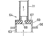
Figure 15,16 is illustrated in and carries out cooling liquid when extracting out, aspirates the direct pumping part 64 of direct cooling liquid from the upper end open to the water pipe 63 of elevated tank 3 inner openings of radiator 6.Above-mentioned radiator core 4 is made up of corrugated fin 65 and water pipe 63, be arranged to make the upper end of water pipe 63 to stretch out slightly upward from top board 66, direct pumping part 64 and above-mentioned flexible pipe 20 or rubber stopper 19 are communicated with, constitute and directly aspirate cooling liquid from the upper end open of water pipe 63.
In this embodiment, as shown in figure 16, above-mentioned direct pumping part 64 comprises flexible pipe 20, connector element 67 has the contact element 69 of rubber or sponge system opening 68, because when negative pressure-pumping, the opening 68 of the contact element 69 that contacts from the upper end open with water pipe 63 is the suction cooling liquids directly, therefore, carry out the structure of negative pressure-pumping cooling liquid relatively from the inlet 2 that forms with rubber stopper 19, have the effect that can improve negative pressure-pumping cooling liquid effect.
In addition, in Figure 15, used rubber stopper 19 and direct pumping part 64 simultaneously, yet also this rubber stopper 19 can have been omitted.In addition, Figure 15,70 in 16 are the radiator bogie side frame, 71 is base plate.
Figure 17 is illustrated in suction and is pumped in the water pipe 63 that stretches out in the radiator 6 top casees 3 and the flexible aspiration means 72 of 66 cooling liquids of top board during cooling liquid, when many flexible aspiration means 72 that formed by flexible members such as rubber hose are connected with above-mentioned rubber stopper 19, a plurality of suction through holes 73 are set on this aspiration means 72.
Above-mentioned flexible aspiration means 72 is inserted in the top case 3 from inlet 2, when this flexure member 72 laid on top board 66, owing to doing the time spent when the inlet gastight closing being produced negative pressure-pumping with rubber stopper 19, can be from 66 suctions of water pipe 63 and top board cooling liquid, have and can reliably prevent betwixt the effect of (be exactly the upper end open of water pipe 63 and top board 66 top between) residual cooling liquid.
Figure 18 represents directly to aspirate the aspirating mechanism of cooling liquid in radiator under casing 5, when the thinner tubule of Guan Jing 74 is connected with above-mentioned rubber stopper 19, make this tubule 74 in water pipe 63 by when being positioned under casing 5, when forming negative pressure-pumping, can under casing 5, directly aspirate cooling liquids.
Figure 19 represents the aspirating mechanism by cooling liquids in the coupled water storage box flexible pipe 75 suction water storage boxs 76 in the positive bottom of the inlet 2 of radiator 6, pipe 77 is connected with above-mentioned rubber stopper 19, after water storage case lid 78 is unloaded, when opening portion 79 inserts aforementioned tube 77 in the water storage box 76 from its upper end, can carry out the negative pressure-pumping of cooling liquid in this water storage box 76.
Claims (6)
1. cooling liquid exchanger for engine, described device comprises:
Cooling liquid with pressure functional port and liquid outflow inlet stores mechanism,
At the detachable detachable lower member that is positioned at down on the radiator plug,
The liquid that makes above-mentioned cooling liquid store mechanism flows out the communication member that detachable lower member is communicated with on inlet and the above-mentioned inlet,
Pressure application mechanism, described pressure application mechanism drive motor when cooling liquid extracts in carrying out engine coolant system, need make the cooling liquid cryogenic overheating, make above-mentioned pressure functional port produce suction function, when supplying with new liquid, make above-mentioned pressure functional port produce positive pressure simultaneously
Described pressure application mechanism comprises pressure conversion mechanism, and described pressure conversion mechanism is made of air ejector, when the outlet port (41) of open this air ejector, forms negative pressure at pressure functional port (16); When the outlet port of roughly closing this air ejector (41), form malleation at pressure functional port (16).
2. device according to claim 1, it is characterized in that, path switching mechanism is set in the middle of the above-mentioned communication member, described path switching mechanism is when extracting cooling liquid and supplying with new liquid, make above-mentioned liquid flow out detachable lower member connection on inlet and the above-mentioned inlet, simultaneously, when reclaiming the cooling liquid of having extracted out, above-mentioned outflow inlet and recovery approach are communicated with by recovering mechanism.
3. cooling liquid exchanger for engine, described device comprises;
Discharge opeing with suction function mouth and liquid inflow entrance stores mechanism,
New liquid with positive pressure mouth and liquid outflow opening stores mechanism, can set up the member that unloads on radiator plug,
Pressure application mechanism, described pressure application mechanism drive motor when cooling liquid extracts in carrying out engine coolant system, need make the cooling liquid cryogenic overheating, make above-mentioned pressure functional port produce suction function, when supplying with new liquid, make above-mentioned pressure functional port produce positive pressure simultaneously
Described pressure application mechanism comprises pressure conversion mechanism, and described pressure conversion mechanism is made of air ejector, when the outlet port (41) of open this air ejector, forms negative pressure at pressure functional port (16); When the outlet port of roughly closing this air ejector (41), form malleation at pressure functional port (16),
And make when extracting cooling liquid that detachable lower member and above-mentioned liquid inflow entrance are communicated with on the above-mentioned inlet, when supplying with new liquid, make above-mentioned liquid outflow opening and above-mentionedly set up and unload the passage switching mechanism that lower member is communicated with.
4. device according to claim 1, it is characterized in that, above-mentioned pressure application mechanism comprise air compressing mechanism and the driving stream that comes from this air compressing mechanism as stream once, produce at above-mentioned pressure functional port, suction function as secondary flow, when increasing the ejection resistance of above-mentioned driving stream, produce the pressure conversion mechanism of positive pressure at above-mentioned pressure functional port simultaneously.
5. device according to claim 1, it is characterized in that, be arranged on when extracting cooling liquid,, make detachable lower member connection on this direct pumping part and above-mentioned communication member or the inlet from directly aspirating the direct pumping part of cooling liquid to the water pipe upper end open of radiator top box inner opening.
6. device according to claim 1, it is characterized in that, a plurality of flexible pumping parts are set in described device, described a plurality of flexible pumping part is when the suction cooling liquid, can be pumped in stretch out and the radiator top box in water pipe and the cooling liquid between upper plate, and make that detachable lower member is communicated with on this flexible pumping part and the above-mentioned inlet.
Priority Applications (1)
| Application Number | Priority Date | Filing Date | Title |
|---|---|---|---|
| CN95114850A CN1069378C (en) | 1995-04-06 | 1995-04-06 | Cooling liquid exchanger for engine |
Applications Claiming Priority (1)
| Application Number | Priority Date | Filing Date | Title |
|---|---|---|---|
| CN95114850A CN1069378C (en) | 1995-04-06 | 1995-04-06 | Cooling liquid exchanger for engine |
Publications (2)
| Publication Number | Publication Date |
|---|---|
| CN1132822A CN1132822A (en) | 1996-10-09 |
| CN1069378C true CN1069378C (en) | 2001-08-08 |
Family
ID=5080338
Family Applications (1)
| Application Number | Title | Priority Date | Filing Date |
|---|---|---|---|
| CN95114850A Expired - Fee Related CN1069378C (en) | 1995-04-06 | 1995-04-06 | Cooling liquid exchanger for engine |
Country Status (1)
| Country | Link |
|---|---|
| CN (1) | CN1069378C (en) |
Families Citing this family (3)
| Publication number | Priority date | Publication date | Assignee | Title |
|---|---|---|---|---|
| CN107304705A (en) * | 2016-04-20 | 2017-10-31 | 宝沃汽车(中国)有限公司 | Low-temperature cooling system and the vehicle with the low-temperature cooling system |
| CN106679251A (en) * | 2016-08-31 | 2017-05-17 | 广东月福汽车用品有限公司 | Cooling system cooling liquid exchanger |
| CN111093350B (en) * | 2020-01-07 | 2021-10-22 | 中国科学院电工研究所 | A liquid injection device |
Citations (1)
| Publication number | Priority date | Publication date | Assignee | Title |
|---|---|---|---|---|
| JPS6183434A (en) * | 1984-09-29 | 1986-04-28 | Nissan Motor Co Ltd | Condenser for evaporative cooling type engine |
-
1995
- 1995-04-06 CN CN95114850A patent/CN1069378C/en not_active Expired - Fee Related
Patent Citations (1)
| Publication number | Priority date | Publication date | Assignee | Title |
|---|---|---|---|---|
| JPS6183434A (en) * | 1984-09-29 | 1986-04-28 | Nissan Motor Co Ltd | Condenser for evaporative cooling type engine |
Also Published As
| Publication number | Publication date |
|---|---|
| CN1132822A (en) | 1996-10-09 |
Similar Documents
| Publication | Publication Date | Title |
|---|---|---|
| JP2800997B2 (en) | Engine coolant changer | |
| US7984699B2 (en) | Cooling system | |
| CN208564736U (en) | A kind of cooling fluid exchange device | |
| CN1132822A (en) | Cooling liquid exchanger for engine | |
| CN109268268B (en) | Marine steam turbine integrated water ring vacuum pump | |
| CN207437190U (en) | A kind of expansion tank and engine-cooling system | |
| KR0120411B1 (en) | Exchange apparatus of engine cooling water | |
| JP3014524U (en) | Engine cooling water exchange device | |
| JP4628934B2 (en) | Waste steam recovery device | |
| EP0722041B1 (en) | Engine coolant changing method and apparatus | |
| CN116902901B (en) | Oil storage container residual oil collection and recovery system | |
| CN213091093U (en) | Air tightness detection device of automobile expansion kettle | |
| JP3104743B2 (en) | Vehicle coolant exchange device and coolant exchange method | |
| CN114132474A (en) | Ship power cabin cooling system for cooling by seawater series flow | |
| CN218345602U (en) | Quench tower for flash spinning | |
| CN223292275U (en) | Vacuum oil filling device for liquid towed array | |
| CN223707742U (en) | Degassing device for engine oil cooler of high-horsepower engine | |
| JP3654106B2 (en) | Liquid injection method and liquid injection device | |
| CN221400431U (en) | A high temperature wax removal vehicle for oil well cleaning | |
| JP5774329B2 (en) | Hose attachment | |
| CN118936124B (en) | Condensate water recovery device for steam heating system and recovery method thereof | |
| CN1235664A (en) | Liquid Filling Method in Thermoelectric Cooling System | |
| JP3014362U (en) | Engine cooling water exchange device | |
| JP2004132295A (en) | Cooling water filling equipment for water-cooled internal combustion engines | |
| CN214299255U (en) | Oil gas recovery membrane type separation device |
Legal Events
| Date | Code | Title | Description |
|---|---|---|---|
| C06 | Publication | ||
| PB01 | Publication | ||
| C10 | Entry into substantive examination | ||
| SE01 | Entry into force of request for substantive examination | ||
| C14 | Grant of patent or utility model | ||
| GR01 | Patent grant | ||
| C17 | Cessation of patent right | ||
| CF01 | Termination of patent right due to non-payment of annual fee |
Granted publication date: 20010808 |