CN106938111B - Syringe identification device, high-pressure injector and control method thereof - Google Patents
Syringe identification device, high-pressure injector and control method thereof Download PDFInfo
- Publication number
- CN106938111B CN106938111B CN201710180086.4A CN201710180086A CN106938111B CN 106938111 B CN106938111 B CN 106938111B CN 201710180086 A CN201710180086 A CN 201710180086A CN 106938111 B CN106938111 B CN 106938111B
- Authority
- CN
- China
- Prior art keywords
- syringe
- needle cylinder
- fixing sleeve
- pressure injector
- panel
- Prior art date
- Legal status (The legal status is an assumption and is not a legal conclusion. Google has not performed a legal analysis and makes no representation as to the accuracy of the status listed.)
- Active
Links
- 238000000034 method Methods 0.000 title claims abstract description 15
- 230000007246 mechanism Effects 0.000 claims abstract description 36
- 238000011900 installation process Methods 0.000 claims description 6
- 238000007789 sealing Methods 0.000 description 20
- 239000000243 solution Substances 0.000 description 7
- 239000003814 drug Substances 0.000 description 5
- 239000007788 liquid Substances 0.000 description 5
- 238000007689 inspection Methods 0.000 description 2
- 238000009434 installation Methods 0.000 description 2
- VYPSYNLAJGMNEJ-UHFFFAOYSA-N Silicium dioxide Chemical compound O=[Si]=O VYPSYNLAJGMNEJ-UHFFFAOYSA-N 0.000 description 1
- 238000005299 abrasion Methods 0.000 description 1
- 239000000853 adhesive Substances 0.000 description 1
- 238000004026 adhesive bonding Methods 0.000 description 1
- 230000001070 adhesive effect Effects 0.000 description 1
- 230000009286 beneficial effect Effects 0.000 description 1
- 230000008094 contradictory effect Effects 0.000 description 1
- 239000002872 contrast media Substances 0.000 description 1
- 238000001514 detection method Methods 0.000 description 1
- 238000002059 diagnostic imaging Methods 0.000 description 1
- 239000013013 elastic material Substances 0.000 description 1
- 238000001746 injection moulding Methods 0.000 description 1
- 238000004519 manufacturing process Methods 0.000 description 1
- 239000000463 material Substances 0.000 description 1
- 238000012986 modification Methods 0.000 description 1
- 230000004048 modification Effects 0.000 description 1
- 238000003825 pressing Methods 0.000 description 1
- 230000002035 prolonged effect Effects 0.000 description 1
- 239000000741 silica gel Substances 0.000 description 1
- 229910002027 silica gel Inorganic materials 0.000 description 1
- 230000003068 static effect Effects 0.000 description 1
Images


Classifications
-
- A—HUMAN NECESSITIES
- A61—MEDICAL OR VETERINARY SCIENCE; HYGIENE
- A61M—DEVICES FOR INTRODUCING MEDIA INTO, OR ONTO, THE BODY; DEVICES FOR TRANSDUCING BODY MEDIA OR FOR TAKING MEDIA FROM THE BODY; DEVICES FOR PRODUCING OR ENDING SLEEP OR STUPOR
- A61M5/00—Devices for bringing media into the body in a subcutaneous, intra-vascular or intramuscular way; Accessories therefor, e.g. filling or cleaning devices, arm-rests
- A61M5/178—Syringes
- A61M5/20—Automatic syringes, e.g. with automatically actuated piston rod, with automatic needle injection, filling automatically
- A61M5/2053—Media being expelled from injector by pressurised fluid or vacuum
-
- A—HUMAN NECESSITIES
- A61—MEDICAL OR VETERINARY SCIENCE; HYGIENE
- A61M—DEVICES FOR INTRODUCING MEDIA INTO, OR ONTO, THE BODY; DEVICES FOR TRANSDUCING BODY MEDIA OR FOR TAKING MEDIA FROM THE BODY; DEVICES FOR PRODUCING OR ENDING SLEEP OR STUPOR
- A61M5/00—Devices for bringing media into the body in a subcutaneous, intra-vascular or intramuscular way; Accessories therefor, e.g. filling or cleaning devices, arm-rests
- A61M5/007—Devices for bringing media into the body in a subcutaneous, intra-vascular or intramuscular way; Accessories therefor, e.g. filling or cleaning devices, arm-rests for contrast media
-
- A—HUMAN NECESSITIES
- A61—MEDICAL OR VETERINARY SCIENCE; HYGIENE
- A61M—DEVICES FOR INTRODUCING MEDIA INTO, OR ONTO, THE BODY; DEVICES FOR TRANSDUCING BODY MEDIA OR FOR TAKING MEDIA FROM THE BODY; DEVICES FOR PRODUCING OR ENDING SLEEP OR STUPOR
- A61M5/00—Devices for bringing media into the body in a subcutaneous, intra-vascular or intramuscular way; Accessories therefor, e.g. filling or cleaning devices, arm-rests
- A61M5/178—Syringes
- A61M5/31—Details
-
- A—HUMAN NECESSITIES
- A61—MEDICAL OR VETERINARY SCIENCE; HYGIENE
- A61M—DEVICES FOR INTRODUCING MEDIA INTO, OR ONTO, THE BODY; DEVICES FOR TRANSDUCING BODY MEDIA OR FOR TAKING MEDIA FROM THE BODY; DEVICES FOR PRODUCING OR ENDING SLEEP OR STUPOR
- A61M5/00—Devices for bringing media into the body in a subcutaneous, intra-vascular or intramuscular way; Accessories therefor, e.g. filling or cleaning devices, arm-rests
- A61M5/178—Syringes
- A61M5/31—Details
- A61M5/3129—Syringe barrels
-
- A—HUMAN NECESSITIES
- A61—MEDICAL OR VETERINARY SCIENCE; HYGIENE
- A61M—DEVICES FOR INTRODUCING MEDIA INTO, OR ONTO, THE BODY; DEVICES FOR TRANSDUCING BODY MEDIA OR FOR TAKING MEDIA FROM THE BODY; DEVICES FOR PRODUCING OR ENDING SLEEP OR STUPOR
- A61M5/00—Devices for bringing media into the body in a subcutaneous, intra-vascular or intramuscular way; Accessories therefor, e.g. filling or cleaning devices, arm-rests
- A61M5/178—Syringes
- A61M5/20—Automatic syringes, e.g. with automatically actuated piston rod, with automatic needle injection, filling automatically
- A61M2005/2006—Having specific accessories
-
- A—HUMAN NECESSITIES
- A61—MEDICAL OR VETERINARY SCIENCE; HYGIENE
- A61M—DEVICES FOR INTRODUCING MEDIA INTO, OR ONTO, THE BODY; DEVICES FOR TRANSDUCING BODY MEDIA OR FOR TAKING MEDIA FROM THE BODY; DEVICES FOR PRODUCING OR ENDING SLEEP OR STUPOR
- A61M5/00—Devices for bringing media into the body in a subcutaneous, intra-vascular or intramuscular way; Accessories therefor, e.g. filling or cleaning devices, arm-rests
- A61M5/178—Syringes
- A61M5/31—Details
- A61M2005/3125—Details specific display means, e.g. to indicate dose setting
-
- A—HUMAN NECESSITIES
- A61—MEDICAL OR VETERINARY SCIENCE; HYGIENE
- A61M—DEVICES FOR INTRODUCING MEDIA INTO, OR ONTO, THE BODY; DEVICES FOR TRANSDUCING BODY MEDIA OR FOR TAKING MEDIA FROM THE BODY; DEVICES FOR PRODUCING OR ENDING SLEEP OR STUPOR
- A61M2205/00—General characteristics of the apparatus
- A61M2205/19—Constructional features of carpules, syringes or blisters
-
- A—HUMAN NECESSITIES
- A61—MEDICAL OR VETERINARY SCIENCE; HYGIENE
- A61M—DEVICES FOR INTRODUCING MEDIA INTO, OR ONTO, THE BODY; DEVICES FOR TRANSDUCING BODY MEDIA OR FOR TAKING MEDIA FROM THE BODY; DEVICES FOR PRODUCING OR ENDING SLEEP OR STUPOR
- A61M2205/00—General characteristics of the apparatus
- A61M2205/33—Controlling, regulating or measuring
-
- A—HUMAN NECESSITIES
- A61—MEDICAL OR VETERINARY SCIENCE; HYGIENE
- A61M—DEVICES FOR INTRODUCING MEDIA INTO, OR ONTO, THE BODY; DEVICES FOR TRANSDUCING BODY MEDIA OR FOR TAKING MEDIA FROM THE BODY; DEVICES FOR PRODUCING OR ENDING SLEEP OR STUPOR
- A61M2205/00—General characteristics of the apparatus
- A61M2205/60—General characteristics of the apparatus with identification means
Landscapes
- Health & Medical Sciences (AREA)
- Vascular Medicine (AREA)
- Engineering & Computer Science (AREA)
- Anesthesiology (AREA)
- Biomedical Technology (AREA)
- Heart & Thoracic Surgery (AREA)
- Hematology (AREA)
- Life Sciences & Earth Sciences (AREA)
- Animal Behavior & Ethology (AREA)
- General Health & Medical Sciences (AREA)
- Public Health (AREA)
- Veterinary Medicine (AREA)
- Infusion, Injection, And Reservoir Apparatuses (AREA)
Abstract
The invention discloses a syringe identification device, a high-pressure injector and a control method thereof, wherein the syringe identification device is applied to the high-pressure injector and comprises the following components: a handpiece panel; the microswitch is fixedly arranged on the handpiece panel; the needle cylinder fixing sleeve is arranged on the handpiece panel, the needle cylinder fixing sleeve rotates relative to the handpiece panel, and the outer edge of the needle cylinder fixing sleeve tightly presses or loosens the trigger mechanism of the microswitch so as to enable the microswitch to be turned on or turned off. The technical scheme of the invention can identify whether the needle cylinder of the high-pressure injector is assembled or not, so that the high-pressure injector is simpler and more convenient to use.
Description
Technical Field
The invention relates to the technical field of medical instruments, in particular to a syringe identification device, a high-pressure injector using the syringe identification device and a control method of the high-pressure injector.
Background
High pressure syringes have been developed as an aid in medical imaging systems, with the development of X-ray machines, rapid film changers, image intensifiers, and artificial contrast agents. Today, high pressure injectors are widely used in various angiographic examinations, CT-enhanced contrast scans and MR-enhanced scans.
However, in the process of assembling the syringe to the handpiece panel of the existing high-pressure injector, whether the syringe is assembled or not needs to be checked by an operator and cannot be automatically identified by a system, so that the condition of missing detection is easy to occur, and the high-pressure injector is inconvenient to use.
Disclosure of Invention
The invention mainly aims to provide a syringe identification device, which aims to identify whether a syringe of a high-pressure injector is assembled or not, so that the high-pressure injector is simpler and more convenient to use.
In order to achieve the above object, the present invention provides a syringe identification device for a high pressure injector, comprising:
a handpiece panel;
the microswitch is fixedly arranged on the handpiece panel;
the needle cylinder fixing sleeve is arranged on the handpiece panel, the needle cylinder fixing sleeve rotates relative to the handpiece panel, and the outer edge of the needle cylinder fixing sleeve tightly presses or loosens the trigger mechanism of the microswitch so as to enable the microswitch to be turned on or turned off.
Optionally, the needle cylinder identification device includes at least two micro switches, two micro switches are arranged at intervals, a rotation start position and a rotation stop position exist in the installation process of the needle cylinder fixedly sleeved with the high-pressure injector, and when the needle cylinder fixedly sleeved with the rotation stop position, the outer edge of the needle cylinder fixedly sleeved with the needle cylinder simultaneously presses two trigger mechanisms of the micro switches, so that the two micro switches are simultaneously turned on.
Optionally, the needle cylinder fixing sleeve includes a fixing sleeve body and a lug arranged on an outer edge of the fixing sleeve body, an assembly groove is formed in one surface of the handpiece panel, the fixing sleeve body is accommodated in the assembly groove, a sliding groove is formed in a side wall of the assembly groove, the lug is accommodated in the sliding groove, a switch mounting position is formed in a side wall of the sliding groove, the microswitch is accommodated in the switch mounting position, and the lug slides in the sliding groove to press or loosen a trigger mechanism of the microswitch.
Optionally, the switch mounting position is provided with one of a mounting post and a mounting hole, the microswitch is provided with the other of the mounting post and the mounting hole, and the mounting post is inserted into the mounting hole.
Optionally, a limit stop is arranged in the sliding groove, and the limit stop abuts against the lug when the lug slides to the trigger mechanism pressing the two micro switches.
Optionally, a plurality of limit stops are arranged in the sliding groove, the needle cylinder fixing sleeve comprises a plurality of lugs, the distance between every two adjacent limit stops along the circumferential direction of the sliding groove is greater than the length of each lug along the circumferential direction of the needle cylinder fixing sleeve, and one limit stop abuts against one lug when one lug slides to press the trigger mechanism of two microswitches.
Optionally, a sealing ring is arranged in the assembly groove and is positioned between the needle cylinder fixing sleeve and the groove wall of the assembly groove.
The invention also provides a high-pressure injector, which comprises a syringe identification device, wherein the syringe identification device comprises:
a handpiece panel;
the microswitch is fixedly arranged on the handpiece panel;
the needle cylinder fixing sleeve is arranged on the handpiece panel, the needle cylinder fixing sleeve rotates relative to the handpiece panel, and the outer edge of the needle cylinder fixing sleeve tightly presses or loosens the trigger mechanism of the microswitch so as to enable the microswitch to be turned on or turned off.
The invention also provides a control method of the high-pressure injector, which comprises the following steps:
the system judges the state of the microswitch;
when the system judges that the state of the microswitch is on, the push rod is controlled to advance to exhaust.
Optionally, the high pressure injector comprises at least two microswitches, and the control method of the high pressure injector comprises the steps of:
the system judges the states of the two micro switches;
when the system judges that the states of the two micro switches are both on, the push rod is controlled to advance to exhaust.
According to the technical scheme, the microswitch and the needle cylinder fixing sleeve are arranged on the machine head panel, the needle cylinder fixing sleeve can rotate relative to the machine head panel, and the outer edge of the needle cylinder fixing sleeve can be pressed or loosened by the trigger mechanism of the microswitch through rotation of the needle cylinder fixing sleeve, so that the microswitch can generate a signal that a needle cylinder is assembled or a signal that the needle cylinder is not assembled (namely a signal that the needle cylinder is not assembled), and further a needle cylinder identification function is achieved, namely whether the needle cylinder of the high-pressure injector is assembled or not can be identified, and the step of manual inspection is avoided.
Drawings
In order to more clearly illustrate the embodiments of the present invention or the technical solutions in the prior art, the drawings used in the description of the embodiments or the prior art will be briefly described below, it is obvious that the drawings in the following description are only some embodiments of the present invention, and for those skilled in the art, other drawings can be obtained according to the structures shown in the drawings without creative efforts.
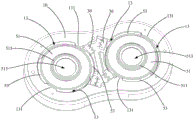
FIG. 1 is a schematic structural view of an embodiment of a syringe identification device according to the present invention;
FIG. 2 is an exploded view of the needle cartridge identification device of FIG. 1;
FIG. 3 is a schematic view of the head panel of FIG. 2 from another perspective;
FIG. 4 is an enlarged view of the needle hub of FIG. 2;
FIG. 5 is a schematic view of the needle hub of FIG. 4 from another perspective;
FIG. 6 is an enlarged schematic view of the microswitch of FIG. 2;
fig. 7 is a schematic view of the assembly structure of the microswitch, the syringe fixing sleeve and the handpiece panel in fig. 2.
The reference numbers illustrate:
| reference numerals | Name (R) | Reference numerals | Name (R) |
| 100 | |
31 | |
| 10 | |
50 | Needle |
| 11 | |
51 | |
| 111 | |
511 | |
| 13 | |
513 | Second yielding through |
| 131 | |
515 | Annular limiting |
| 15 | |
53 | Convex |
| 151 | |
70 | |
| 17 | First yielding through |
71 | Third yielding through |
| 30 | Micro-switch |
The implementation, functional features and advantages of the objects of the present invention will be further explained with reference to the accompanying drawings.
Detailed Description
The technical solutions in the embodiments of the present invention will be described clearly and completely with reference to the drawings in the embodiments of the present invention, and it is obvious that the described embodiments are only a part of the embodiments of the present invention, and not all of the embodiments. All other embodiments, which can be derived by a person skilled in the art from the embodiments given herein without making any creative effort, shall fall within the protection scope of the present invention.
It should be noted that all the directional indicators (such as upper, lower, left, right, front, and rear … …) in the embodiment of the present invention are only used to explain the relative position relationship between the components, the motion situation, and the like in a specific posture (as shown in the drawing), and if the specific posture is changed, the directional indicator is changed accordingly.
In addition, the descriptions related to "first", "second", etc. in the present invention are only for descriptive purposes and are not to be construed as indicating or implying relative importance or implicitly indicating the number of technical features indicated. Thus, a feature defined as "first" or "second" may explicitly or implicitly include at least one such feature. In the description of the present invention, "a plurality" means at least two, e.g., two, three, etc., unless specifically limited otherwise.
In the present invention, unless otherwise expressly stated or limited, the terms "connected," "secured," and the like are to be construed broadly, and for example, "secured" may be a fixed connection, a removable connection, or an integral part; can be mechanically or electrically connected; they may be directly connected or indirectly connected through intervening media, or they may be connected internally or in any other suitable relationship, unless expressly stated otherwise. The specific meanings of the above terms in the present invention can be understood according to specific situations by those of ordinary skill in the art.
In addition, the technical solutions in the embodiments of the present invention may be combined with each other, but it must be based on the realization of those skilled in the art, and when the technical solutions are contradictory or cannot be realized, such a combination of technical solutions should not be considered to exist, and is not within the protection scope of the present invention.
The present invention provides a syringe identification apparatus 100, which is mainly applied to a high-pressure injector to automatically identify whether a syringe is installed.
As shown in fig. 1 to 7, the specific structure of the syringe identification apparatus 100 will be described, and in an embodiment of the syringe identification apparatus 100 according to the present invention, the syringe identification apparatus 100 includes:
a head panel 10;
the microswitch 30 is fixedly arranged on the handpiece panel 10;
the needle cylinder fixing sleeve 50 is mounted on the handpiece panel 10, the needle cylinder fixing sleeve 50 rotates relative to the handpiece panel 10, and the outer edge of the needle cylinder fixing sleeve 50 tightly presses or loosens the trigger mechanism of the microswitch 30, so that the microswitch 30 is turned on or turned off.
In this embodiment, the syringe retaining sleeve 50 is substantially circular and includes a retaining sleeve body 51 and a protrusion 53 disposed on the outer edge of the retaining sleeve body 51. The lugs 53 extend circumferentially of the syringe retaining sleeve 50 and are in the form of arcuate segments. Accordingly, a surface of the head panel 10 is formed with an assembly slot 11, and the fixing sleeve body 51 is received in the assembly slot 11 and can rotate in the assembly slot 11. The side wall of the assembly slot 11 is opened with a sliding slot 13, when the fixing sleeve body 51 is accommodated in the assembly slot 11, the lug 53 is accommodated in the sliding slot 13, and when the fixing sleeve body 51 rotates in the assembly slot 11, the lug 53 slides in the sliding slot 13 along with the rotation of the fixing sleeve body 51. The bottom wall 111 of the assembly groove 11 is provided with a first abdicating through hole 17 through which a needle cylinder of the high-pressure syringe passes, and the fixing sleeve body 51 is provided with a second abdicating through hole 513 through which a push rod of the high-pressure syringe passes facing the first abdicating through hole 17. That is, the first abdicating through hole 17 penetrates the handpiece panel 10, the second abdicating through hole 513 penetrates the syringe fixing sleeve 50 and is communicated with the first abdicating through hole 17, at this time, the syringe of the high-pressure injector can pass through the first abdicating through hole 17 of the handpiece panel 10 and is fixedly connected with the syringe fixing sleeve 50, the push rod of the high-pressure injector can pass through the second abdicating through hole 513 of the syringe fixing sleeve 50 and is connected with the syringe, and then the system controls the push rod to reciprocate in the syringe, so as to complete automatic exhaust and automatic return.
Further, a switch mounting position 15 is disposed on a side wall of the sliding slot 13, the micro switch 30 is accommodated in the switch mounting position 15, and the trigger mechanism of the micro switch 30 is exposed from the switch mounting position 15. Specifically, when the syringe fixing sleeve 50 is mounted on the handpiece panel 10 and located at the initial position, that is, the fixing sleeve body 51 is accommodated in the assembly slot 11, the lug 53 is accommodated in the slide slot 13, and both are located at the initial position, the lug 53 is not in contact with the trigger mechanism of the micro switch 30, the trigger mechanism of the micro switch 30 is in a released state, that is, the micro switch 30 is in a closed state, at this time, the micro switch 30 does not send information to the system, the system determines that the syringe is not mounted, and executes the plunger retraction operation until the plunger retracts, so as to facilitate the next syringe mounting. When an operator installs and fixes the syringe to the syringe fixing sleeve 50 and rotates the syringe by a certain angle until the syringe is clamped on the handpiece panel 10, the syringe fixing sleeve 50 is also rotated by a certain angle under the driving of the syringe, at the moment, the lug 53 slides in the chute 13 by a certain distance and contacts and presses the trigger mechanism of the microswitch 30, so that the microswitch 30 is in an open state and sends information to the system, the system further judges that the syringe is installed, and the push rod advancing operation is executed to exhaust so as to directly perform the liquid medicine suction operation. When the operator rotates the used syringe to the initial position, the lug 53 is separated from the trigger mechanism of the microswitch 30, the trigger mechanism of the microswitch 30 is restored to the release state, that is, the microswitch 30 is restored to the off state, at this time, the microswitch 30 does not send information to the system, the system judges that the syringe is not installed, and the push rod is retreated until the push rod retreats. It will be appreciated that the above arrangement allows the syringe identification device 100 to be more compact and efficient, not only for ease of manufacture, but also for low resource consumption. Moreover, the needle cylinder recognition device 100 is simple in structure, convenient to install, convenient to use and high in practicability.
Therefore, it can be understood that, according to the technical scheme of the present invention, the micro switch 30 and the syringe fixing sleeve 50 are arranged on the handpiece panel 10, and the syringe fixing sleeve 50 can rotate relative to the handpiece panel 10, so that the outer edge of the syringe fixing sleeve 50 can press or loosen the trigger mechanism of the micro switch 30 through the rotation of the syringe fixing sleeve 50, so that the micro switch 30 can generate a signal that the syringe is assembled or a signal that the syringe is not assembled (i.e., a signal that the syringe is not assembled), thereby realizing the syringe identification function, i.e., identifying whether the syringe of the high-pressure injector is assembled or not, and avoiding the step of manual inspection.
It should be noted that, as shown in fig. 2, in the present embodiment, the handpiece panel 10 includes two fitting slots 11, each fitting slot 11 is provided with a sliding slot 13, and each sliding slot 13 is provided with two switch mounting positions 15. Accordingly, the syringe identification device 100 includes a two-syringe retaining sleeve 50. The positional relationship, the connection relationship, and/or the assembly relationship of these components are as described above, and are not described in detail herein. Moreover, it is to be understood that in other embodiments, the number of components included in the syringe identification apparatus 100 may be adjusted accordingly according to the actual situation.
As shown in fig. 2, fig. 3 and fig. 7, the syringe identification apparatus 100 includes at least two micro switches 30, the two micro switches 30 are arranged at intervals, the syringe fixing sleeve 50 has a rotation start position and a rotation stop position in the installation process of the syringe of the high-pressure injector, and when the syringe fixing sleeve 50 is located at the rotation stop position, the outer edge of the syringe fixing sleeve 50 simultaneously presses the trigger mechanisms of the two micro switches 30, so that the two micro switches 30 are simultaneously turned on.
In this embodiment, the triggering mechanisms of the two microswitches 30 are distributed at intervals on the sliding path of the lug 53, and the lug 53 has a sliding start position and a sliding stop position in the installation process of the syringe of the high-pressure injector, relative to the rotating start position and the rotating stop position of the syringe fixing sleeve 50. Therefore, when the syringe fixing sleeve 50 is rotated to the rotation stop position, i.e. when the lug 53 slides to the slide stop position, the lug 53 simultaneously presses the trigger mechanisms of the two micro-switches 30, so that the two micro-switches 30 are simultaneously turned on.
It can be understood that, when the trigger mechanism of a micro switch 30 is compressed, the syringe is installed on the panel of the system identification handpiece, further, when the trigger mechanism of another micro switch 30 is also compressed, the system further identifies that the syringe on the panel of the handpiece is installed in place, at this moment, the installation stability of the syringe is higher, the time for the system to execute the push rod pushing operation is more suitable, so that the identification performance of the syringe identification device 100 is more excellent, the push rod can be effectively and smoothly pushed, the operation safety of related structures is ensured, and the precision of the high-pressure injector is ensured.
When the needle cylinder fixing sleeve 50 is located at the rotation starting position, the outer edge of the needle cylinder fixing sleeve 50 simultaneously releases the trigger mechanisms of the two micro switches 30, so that the two micro switches 30 are simultaneously closed.
It will be appreciated that when the syringe retaining sleeve 50 is in or rotated back again to the rotational start position, i.e., when the lugs 53 are in or slid back again to the sliding start position, the lugs 53 simultaneously release the trigger mechanisms of the two microswitches 30 to cause the two microswitches 30 to close simultaneously, at which point the system will only recognize that a syringe is not installed on the handpiece faceplate or that a syringe has been removed.
Due to the arrangement, the situation that the needle cylinder is still positioned on the head panel when the single microswitch 30 is not in contact with the needle cylinder fixing sleeve 50 in the needle cylinder dismounting process can be effectively avoided, so that the accuracy of the system for judging whether the needle cylinder is mounted on the head panel is effectively improved, the time for the system to execute the push rod returning operation is more suitable, the operation of a related structure is safer, and the precision of the high-pressure injector is not damaged.
When the needle cylinder fixing sleeve 50 is located between the rotation start position and the rotation stop position, the outer edge of the needle cylinder fixing sleeve 50 only presses one of the two micro switches 30.
It will be appreciated that when the lug 53 is located between the slide start position and the slide stop position, the lug 53 presses the trigger mechanism of only one of the two microswitches 30. At the moment, the system identifies that the needle cylinder mounting process or the needle cylinder dismounting process exists on the handpiece panel, the system is kept static without any operation, so that the damage of misoperation to related parts is avoided, and the precision of the high-pressure injector is ensured.
As shown in fig. 3, 6 and 7, the switch mounting position 15 is provided with one of a mounting post 151 and a mounting hole 31, the microswitch 30 is provided with the other of the mounting post 151 and the mounting hole 31, and the mounting post 151 is inserted into the mounting hole 31.
In this embodiment, each micro switch 30 is provided with two mounting holes 31, the axes of the two mounting holes 31 are arranged in parallel, and correspondingly, each switch mounting position 15 is provided with two mounting posts 151, and the axes of the two mounting posts 151 are also arranged in parallel. When a micro-switch 30 is mounted to a switch mounting location 15, the two mounting posts 151 of the switch mounting location 15 are respectively inserted into and held in the two mounting holes 31 of the micro-switch 30, so that the micro-switch 30 can be fixed.
So, can effectively improve micro-gap switch 30 set up stability to make micro-gap switch 30 more accurate and more stable with the fixed cover 50's of cylinder cooperation, and then effectively promote cylinder recognition device 100's recognition accuracy.
As shown in fig. 3 to 5 and 7, a limit stopper 131 is disposed in the sliding groove 13, and the limit stopper 131 abuts against the lug 53 when the lug 53 slides to press the trigger mechanism of the two micro switches 30.
It can be understood that, the arrangement of the limit stopper 131 can effectively limit the rotation of the needle cylinder and the needle cylinder fixing sleeve 50 when the lug 53 presses the trigger mechanism of the two micro switches 30 at the same time, so as to prevent the lug 53 from being separated from the trigger mechanism of the micro switch 30 due to the excessive rotation of the needle cylinder and the needle cylinder fixing sleeve 50, thereby ensuring the contact stability of the lug 53 and the micro switch 30 and improving the identification accuracy of the needle cylinder identification device 100.
Preferably, a plurality of the limit stops 131 are arranged in the sliding slot 13, the syringe fixing sleeve 50 includes a plurality of the lugs 53, the distance between every two adjacent limit stops 131 along the circumferential direction of the sliding slot 13 is greater than the length of each lug 53 along the circumferential direction of the syringe fixing sleeve 50, and one limit stop 131 abuts against one lug 53 when one lug 53 slides to press the trigger mechanism of two microswitches 30.
In this embodiment, the nose panel 10 includes two limit stoppers 131, and the two limit stoppers 131 are uniformly distributed along the circumferential direction of the chute 13 and divide the chute 13 into two sections. Accordingly, the syringe retaining sleeve 50 includes two lugs 53, the two lugs 53 being evenly distributed along the circumference of the syringe retaining sleeve 50. Specifically, when the needle cartridge retaining sleeve 50 needs to be mounted on the handpiece panel 10, the mounting can be completed only by placing the retaining sleeve body 51 in the fitting groove and placing the two lugs 53 in the two sliding grooves 13 between the two limit stops 131. Then, if the syringe is fixed to the syringe fixing sleeve 50, the syringe (the syringe fixing sleeve 50 is rotated) only by rotating the syringe until one lug 53 abuts against one limit stop 131, and one lug 53 can simultaneously press the trigger mechanisms of the two micro switches 30, so that the two micro switches 30 are simultaneously opened, thereby sending a signal to prompt that the syringe is installed in place, and the system controls the push rod to automatically exhaust.
It can be understood that, with such an arrangement, while the stability of the contact between the lug 53 and the microswitch 30 is ensured and the identification accuracy of the syringe identification device 100 is improved, the installation process of the syringe and the syringe fixing sleeve 50 can be simpler and more convenient, so that the installation process is effectively simplified and the installation efficiency is improved.
As shown in fig. 2 to 4 and 7, a sealing ring (not shown) is provided in the mounting groove 11 and is located between the syringe fixing sleeve 50 and the wall of the mounting groove 11.
In this embodiment, the sealing ring is located between the bottom wall 111 of the assembly groove 11 and the surface of the syringe fixing sleeve 50 facing the bottom wall 111 of the assembly groove 11, and can seal the gap between the bottom wall 111 of the assembly groove 11 and the surface of the syringe fixing sleeve 50 facing the bottom wall 111 of the assembly groove 11, so as to improve the tightness of the syringe mounted on the syringe fixing sleeve 50, prevent the liquid medicine in the syringe from overflowing, and avoid the liquid medicine loss.
Of course, in other embodiments, the sealing ring may also be disposed between the sidewall of the assembling slot 11 and the surface of the syringe fixing sleeve 50 facing the sidewall of the assembling slot 11, so as to seal the gap between the sidewall of the assembling slot 11 and the surface of the syringe fixing sleeve 50 facing the sidewall of the assembling slot 11, and also improve the tightness of the syringe mounted on the syringe fixing sleeve 50.
Specifically, the surface of the syringe fixing sleeve 50 facing the wall of the mounting groove 11 is provided with an annular mounting groove 511, and the sealing ring is mounted in the annular mounting groove 511.
It can be understood that, such structure setting can effectively promote the stability that sets up of sealing washer, prevents that the sealing washer from taking place to misplace, overlap even in the use of high pressure syringe to avoid sealing washer dislocation, overlap to cause the influence to the cylinder leakproofness, and then effectively ensure the sealing performance of sealing washer, the leakproofness of guarantee cylinder.
Certainly, in other embodiments, the sealing ring can also adopt a gluing mode, a clamping mode, a double-layer injection molding mode or other effective modes to realize stable setting and guarantee the tightness of the needle cylinder.
It should be noted that the material of the sealing ring may be silica gel, rubber, or other elastic materials. Therefore, no matter the fixing mode of the sealing ring or the sealing mode of the sealing ring to the gap can be realized by adopting an interference fit mode, so that the setting stability and the sealing performance of the sealing ring are further improved.
Moreover, it can be understood that, after the high-pressure injector to which the syringe identification apparatus 100 of the present embodiment is applied is used for a long time, when the gap between the head panel 10 and the syringe fixing sleeve 50 is enlarged due to the loosening and/or abrasion of the structural fit, the elastic sealing ring can adopt the interference fit in the earlier stage, at this time, the high-pressure injector still has good sealing performance, that is, the gap between the groove wall of the assembly groove 11 and the surface of the syringe fixing sleeve 50 facing the groove wall of the assembly groove 11 can be effectively sealed, so as to prevent the liquid medicine in the syringe from overflowing, avoid the liquid medicine loss, and effectively ensure the normal working performance of the high-pressure injector, and at the same time, the replacement frequency of the sealing ring is also reduced, the resources are saved, and the practical performance of the syringe identification apparatus 100 is further improved.
As shown in fig. 2, 5 and 7, the syringe identification apparatus 100 further includes a head cover plate 70, the head cover plate 70 covers the assembly slot 11, and a third abdicating through hole 71 for the push rod to pass through is opened at a position of the head cover plate 70 facing the second abdicating through hole 513.
In this embodiment, the head cover plate 70 is formed with two third yielding through holes 71 respectively communicating with the second yielding through holes 513 of the two needle cylinder fixing sleeves 50. Moreover, the surface of the syringe fixing sleeve 50 away from the bottom wall 111 of the assembling groove 11 is further provided with an annular limiting rib 515, and the annular limiting rib 515 is disposed around the second abdicating through hole 513, is accommodated in the corresponding third abdicating through hole 71, and abuts against the side wall of the third abdicating through hole 71. Specifically, the handpiece cover plate 70 can be fixed to the handpiece panel 10 by a snap connection, an adhesive connection, a screw connection, or other effective connection.
It can be understood that, through the arrangement of the head cover plate 70, not only the arrangement stability of the needle cylinder fixing sleeve 50 can be effectively improved, the use accuracy of the high-pressure injector is improved, but also the needle cylinder fixing sleeve 50 and the microswitch 30 can be protected, and the service life of the needle cylinder identification device 100 is prolonged. In addition, the arrangement of the annular limiting rib 515 can further improve the stability of the needle cylinder and the needle cylinder fixing sleeve 50 during rotation, thereby further effectively improving the working accuracy and the practicability of the needle cylinder identification device 100.
The present invention further provides a high-pressure injector, which includes a syringe and the syringe identification apparatus 100 as described above, and the specific structure of the syringe identification apparatus 100 refers to the foregoing embodiments, and since the high-pressure injector adopts all technical solutions of all the foregoing embodiments, the high-pressure injector at least has all beneficial effects brought by the technical solutions of the foregoing embodiments, and details are not repeated herein.
The needle cylinder fixing sleeve 50 of the needle cylinder identification device 100 is sleeved at the bottom of the needle cylinder, and the needle cylinder rotates to drive the needle cylinder fixing sleeve 50 to rotate.
The invention also provides a control method of the high-pressure injector, which comprises the following steps:
the system judges the state of the microswitch 30;
when the system judges that the state of the microswitch 30 is open, the push rod is controlled to advance to exhaust;
when the system judges that the state of the microswitch 30 is closed, the push rod is controlled to retreat and retreat.
When the high-pressure injector comprises at least two micro switches 30, the control method of the high-pressure injector comprises the following steps:
the system judges the states of the two micro switches 30;
when the system judges that the states of the two micro switches 30 are both on, the push rod is controlled to advance to exhaust;
when the system judges that the states of the two micro switches 30 are both off, the push rod is controlled to retreat and retreat;
when the system determines that one of the two microswitch 30 states is off, it remains stationary.
The above description is only a preferred embodiment of the present invention, and is not intended to limit the scope of the present invention, and all modifications and equivalents of the present invention, which are made by the contents of the present specification and the accompanying drawings, or directly/indirectly applied to other related technical fields, are included in the scope of the present invention.
Claims (9)
1. A syringe identification device for use with a high pressure injector, comprising:
a handpiece panel;
the needle cylinder fixing sleeve is arranged on the machine head panel and rotates relative to the machine head panel; and
the two microswitches are fixedly arranged on the handpiece panel, are arranged at intervals and are positioned on the same side of the needle cylinder fixing sleeve, the outer edge of the needle cylinder fixing sleeve tightly presses or loosens a trigger mechanism of the microswitches to enable the microswitches to be turned on or off, a rotation starting position and a rotation stopping position exist in the installation process of the needle cylinder of the high-pressure injector, and when the needle cylinder fixing sleeve is positioned at the rotation stopping position, the outer edge of the needle cylinder fixing sleeve simultaneously presses the trigger mechanisms of the two microswitches to enable the two microswitches to be turned on simultaneously;
when the trigger mechanism of one microswitch is pressed, the system identifies that the needle cylinder is installed on the handpiece panel, and when the trigger mechanism of the other microswitch is also pressed, the system further identifies that the needle cylinder on the handpiece panel is installed in place.
2. The syringe identification device of claim 1, wherein the syringe retaining sleeve comprises a retaining sleeve body and a lug disposed on an outer edge of the retaining sleeve body, wherein a surface of the handpiece panel defines an assembly slot, the retaining sleeve body is received in the assembly slot, a side wall of the assembly slot defines a sliding slot, the lug is received in the sliding slot, a side wall of the sliding slot defines a switch mounting location, the micro switch is received in the switch mounting location, and the lug slides in the sliding slot to press or release the trigger mechanism of the micro switch.
3. The cylinder identification device according to claim 2, wherein said switch mounting portion is provided with one of a mounting post and a mounting hole, said micro switch is provided with the other of a mounting post and a mounting hole, and said mounting post is inserted into said mounting hole.
4. The device according to claim 2, wherein a limit stop is provided in said slot, said limit stop abutting against said lug when said lug slides to press against said trigger mechanism of said microswitch.
5. The syringe identification apparatus of claim 4 wherein said slide slot has a plurality of said limit stops disposed therein, said syringe retaining sleeve includes a plurality of said tabs, the spacing between each two adjacent limit stops along the circumferential direction of said slide slot is greater than the length of each said tab along the circumferential direction of said syringe retaining sleeve, and one said limit stop abuts one said tab when one said tab slides until it compresses the trigger mechanism of two said microswitches.
6. The syringe identification apparatus of any of claims 2-5, wherein a seal is disposed in said mounting slot between said syringe retaining sleeve and a wall of said mounting slot.
7. A high pressure injector, characterized in that it comprises a syringe identification device according to any of claims 1 to 6.
8. A control method of a high pressure injector applied to the high pressure injector of claim 7, comprising the steps of:
the system judges the state of the microswitch;
when the system judges that the state of the microswitch is on, the push rod is controlled to advance to exhaust.
9. The method of controlling a high pressure injector of claim 8, wherein said high pressure injector includes at least two microswitches, said method of controlling a high pressure injector comprising the steps of:
the system judges the states of the two micro switches;
when the system judges that the states of the two micro switches are both on, the push rod is controlled to advance to exhaust.
Priority Applications (1)
| Application Number | Priority Date | Filing Date | Title |
|---|---|---|---|
| CN201710180086.4A CN106938111B (en) | 2017-03-21 | 2017-03-21 | Syringe identification device, high-pressure injector and control method thereof |
Applications Claiming Priority (1)
| Application Number | Priority Date | Filing Date | Title |
|---|---|---|---|
| CN201710180086.4A CN106938111B (en) | 2017-03-21 | 2017-03-21 | Syringe identification device, high-pressure injector and control method thereof |
Publications (2)
| Publication Number | Publication Date |
|---|---|
| CN106938111A CN106938111A (en) | 2017-07-11 |
| CN106938111B true CN106938111B (en) | 2023-03-07 |
Family
ID=59463657
Family Applications (1)
| Application Number | Title | Priority Date | Filing Date |
|---|---|---|---|
| CN201710180086.4A Active CN106938111B (en) | 2017-03-21 | 2017-03-21 | Syringe identification device, high-pressure injector and control method thereof |
Country Status (1)
| Country | Link |
|---|---|
| CN (1) | CN106938111B (en) |
Families Citing this family (1)
| Publication number | Priority date | Publication date | Assignee | Title |
|---|---|---|---|---|
| CN110882444A (en) * | 2019-12-09 | 2020-03-17 | 深圳安科高技术股份有限公司 | High-pressure syringe fixes detection device that targets in place |
Citations (9)
| Publication number | Priority date | Publication date | Assignee | Title |
|---|---|---|---|---|
| CN1167445A (en) * | 1994-11-29 | 1997-12-10 | 阿斯特拉公司 | Dose indicating device |
| JP2003070911A (en) * | 2001-09-04 | 2003-03-11 | Suugan Kk | Syringe and injector head |
| CN102847209A (en) * | 2012-08-29 | 2013-01-02 | 深圳市好克光电仪器有限公司 | Injector identification system and injection pump |
| CN103228304A (en) * | 2010-11-18 | 2013-07-31 | 松下电器产业株式会社 | Drug injection device |
| CN204723522U (en) * | 2015-06-20 | 2015-10-28 | 南京感控通化工产品经营部 | There is the high pressure injector syringe erecting device of opto-coupled feedback |
| CN105194767A (en) * | 2015-11-13 | 2015-12-30 | 南京感控通化工产品经营部 | Needle cylinder mounting and fixing device of high-pressure injector |
| CN205235093U (en) * | 2015-11-24 | 2016-05-18 | 北京来普惠康医学技术有限公司 | Syringe pump pushing hands seat |
| CN205903495U (en) * | 2016-06-15 | 2017-01-25 | 深圳市信冠机电有限公司 | High -pressure syringe |
| CN207477752U (en) * | 2017-03-21 | 2018-06-12 | 深圳安特医疗股份有限公司 | Syringe identification device and high pressure injector |
Family Cites Families (3)
| Publication number | Priority date | Publication date | Assignee | Title |
|---|---|---|---|---|
| CN102116603B (en) * | 2009-12-31 | 2012-10-03 | 北京谊安医疗系统股份有限公司 | Installation in-place detection mechanism of injector flange used for injection pump |
| CN203083526U (en) * | 2012-12-28 | 2013-07-24 | 刘仲馨 | Injector clamping position detection device of micro-injection pump product |
| CN204346463U (en) * | 2014-12-03 | 2015-05-20 | 深圳市好克光电仪器有限公司 | Syringe clamping is to level detecting apparatus |
-
2017
- 2017-03-21 CN CN201710180086.4A patent/CN106938111B/en active Active
Patent Citations (9)
| Publication number | Priority date | Publication date | Assignee | Title |
|---|---|---|---|---|
| CN1167445A (en) * | 1994-11-29 | 1997-12-10 | 阿斯特拉公司 | Dose indicating device |
| JP2003070911A (en) * | 2001-09-04 | 2003-03-11 | Suugan Kk | Syringe and injector head |
| CN103228304A (en) * | 2010-11-18 | 2013-07-31 | 松下电器产业株式会社 | Drug injection device |
| CN102847209A (en) * | 2012-08-29 | 2013-01-02 | 深圳市好克光电仪器有限公司 | Injector identification system and injection pump |
| CN204723522U (en) * | 2015-06-20 | 2015-10-28 | 南京感控通化工产品经营部 | There is the high pressure injector syringe erecting device of opto-coupled feedback |
| CN105194767A (en) * | 2015-11-13 | 2015-12-30 | 南京感控通化工产品经营部 | Needle cylinder mounting and fixing device of high-pressure injector |
| CN205235093U (en) * | 2015-11-24 | 2016-05-18 | 北京来普惠康医学技术有限公司 | Syringe pump pushing hands seat |
| CN205903495U (en) * | 2016-06-15 | 2017-01-25 | 深圳市信冠机电有限公司 | High -pressure syringe |
| CN207477752U (en) * | 2017-03-21 | 2018-06-12 | 深圳安特医疗股份有限公司 | Syringe identification device and high pressure injector |
Also Published As
| Publication number | Publication date |
|---|---|
| CN106938111A (en) | 2017-07-11 |
Similar Documents
| Publication | Publication Date | Title |
|---|---|---|
| KR100947793B1 (en) | Injector Barrel and Cylinder Support | |
| JP2002224218A (en) | Syringe outer cylinder and cylinder holder | |
| TW200406237A (en) | Syringe pump | |
| JP5755700B2 (en) | Syringe | |
| US7695456B2 (en) | Medicament delivery device | |
| CN106823070B (en) | Syringe identification device, high-pressure injector and control method thereof | |
| EP2738399A2 (en) | Connector | |
| CN220938712U (en) | Syringe protection device and safety syringe | |
| CN207477752U (en) | Syringe identification device and high pressure injector | |
| CN220938713U (en) | Syringe protection device and safety syringe | |
| CN110882444A (en) | High-pressure syringe fixes detection device that targets in place | |
| CN220917882U (en) | Syringe protection device and safety syringe | |
| WO2013142264A2 (en) | Syringe pump with replaceable syringe cartridges | |
| CN218338779U (en) | Split type protection type syringe device | |
| CN219721559U (en) | Push device for syringe | |
| CN218293868U (en) | Compressor sealing structure, compressor electric control box and compressor | |
| CN114146260B (en) | Safety syringe device | |
| CN111202680B (en) | Automatic medicine sucking machine | |
| CN111166348B (en) | Blood taking needle | |
| CN106938111A (en) | Syringe identifying device, high pressure injector and its control method | |
| WO2025228202A1 (en) | Injection apparatus and injection mechanism | |
| CN112169933A (en) | Parathyroid gland homogenate breaker | |
| CN223082040U (en) | High-pressure injector | |
| CN216137255U (en) | Liquid-transfering gun head that uses in a flexible way | |
| JP5535256B2 (en) | Syringe, cylinder holder, and chemical injection system |
Legal Events
| Date | Code | Title | Description |
|---|---|---|---|
| PB01 | Publication | ||
| PB01 | Publication | ||
| SE01 | Entry into force of request for substantive examination | ||
| SE01 | Entry into force of request for substantive examination | ||
| CB02 | Change of applicant information |
Address after: 518000 Jinhui Road, Pingshan New District, Shenzhen, Guangdong Province, No. 18 Applicant after: SHENZHEN ANTMED Co.,Ltd. Address before: 518052 Jinhui Road, Pingshan New District, Shenzhen, Guangdong Province, No. 18 Applicant before: SHENZHEN ANT HI-TECH INDUSTRIAL CO.,LTD. |
|
| CB02 | Change of applicant information | ||
| GR01 | Patent grant | ||
| GR01 | Patent grant |