CN106938441B - Device for finishing a workpiece - Google Patents
Device for finishing a workpiece Download PDFInfo
- Publication number
- CN106938441B CN106938441B CN201610826094.7A CN201610826094A CN106938441B CN 106938441 B CN106938441 B CN 106938441B CN 201610826094 A CN201610826094 A CN 201610826094A CN 106938441 B CN106938441 B CN 106938441B
- Authority
- CN
- China
- Prior art keywords
- force
- axis
- measuring device
- tool
- tool mandrel
- Prior art date
- Legal status (The legal status is an assumption and is not a legal conclusion. Google has not performed a legal analysis and makes no representation as to the accuracy of the status listed.)
- Expired - Fee Related
Links
Images


Classifications
-
- B—PERFORMING OPERATIONS; TRANSPORTING
- B24—GRINDING; POLISHING
- B24B—MACHINES, DEVICES, OR PROCESSES FOR GRINDING OR POLISHING; DRESSING OR CONDITIONING OF ABRADING SURFACES; FEEDING OF GRINDING, POLISHING, OR LAPPING AGENTS
- B24B49/00—Measuring or gauging equipment for controlling the feed movement of the grinding tool or work; Arrangements of indicating or measuring equipment, e.g. for indicating the start of the grinding operation
-
- B—PERFORMING OPERATIONS; TRANSPORTING
- B24—GRINDING; POLISHING
- B24B—MACHINES, DEVICES, OR PROCESSES FOR GRINDING OR POLISHING; DRESSING OR CONDITIONING OF ABRADING SURFACES; FEEDING OF GRINDING, POLISHING, OR LAPPING AGENTS
- B24B33/00—Honing machines or devices; Accessories therefor
- B24B33/055—Honing machines or devices; Accessories therefor designed for working plane surfaces
-
- B—PERFORMING OPERATIONS; TRANSPORTING
- B24—GRINDING; POLISHING
- B24B—MACHINES, DEVICES, OR PROCESSES FOR GRINDING OR POLISHING; DRESSING OR CONDITIONING OF ABRADING SURFACES; FEEDING OF GRINDING, POLISHING, OR LAPPING AGENTS
- B24B19/00—Single-purpose machines or devices for particular grinding operations not covered by any other main group
-
- B—PERFORMING OPERATIONS; TRANSPORTING
- B24—GRINDING; POLISHING
- B24B—MACHINES, DEVICES, OR PROCESSES FOR GRINDING OR POLISHING; DRESSING OR CONDITIONING OF ABRADING SURFACES; FEEDING OF GRINDING, POLISHING, OR LAPPING AGENTS
- B24B33/00—Honing machines or devices; Accessories therefor
- B24B33/06—Honing machines or devices; Accessories therefor with controlling or gauging equipment
-
- B—PERFORMING OPERATIONS; TRANSPORTING
- B24—GRINDING; POLISHING
- B24B—MACHINES, DEVICES, OR PROCESSES FOR GRINDING OR POLISHING; DRESSING OR CONDITIONING OF ABRADING SURFACES; FEEDING OF GRINDING, POLISHING, OR LAPPING AGENTS
- B24B35/00—Machines or devices designed for superfinishing surfaces on work, i.e. by means of abrading blocks reciprocating with high frequency
-
- B—PERFORMING OPERATIONS; TRANSPORTING
- B24—GRINDING; POLISHING
- B24B—MACHINES, DEVICES, OR PROCESSES FOR GRINDING OR POLISHING; DRESSING OR CONDITIONING OF ABRADING SURFACES; FEEDING OF GRINDING, POLISHING, OR LAPPING AGENTS
- B24B41/00—Component parts such as frames, beds, carriages, headstocks
- B24B41/007—Weight compensation; Temperature compensation; Vibration damping
-
- B—PERFORMING OPERATIONS; TRANSPORTING
- B24—GRINDING; POLISHING
- B24B—MACHINES, DEVICES, OR PROCESSES FOR GRINDING OR POLISHING; DRESSING OR CONDITIONING OF ABRADING SURFACES; FEEDING OF GRINDING, POLISHING, OR LAPPING AGENTS
- B24B49/00—Measuring or gauging equipment for controlling the feed movement of the grinding tool or work; Arrangements of indicating or measuring equipment, e.g. for indicating the start of the grinding operation
- B24B49/16—Measuring or gauging equipment for controlling the feed movement of the grinding tool or work; Arrangements of indicating or measuring equipment, e.g. for indicating the start of the grinding operation taking regard of the load
Landscapes
- Engineering & Computer Science (AREA)
- Mechanical Engineering (AREA)
- Force Measurement Appropriate To Specific Purposes (AREA)
- Constituent Portions Of Griding Lathes, Driving, Sensing And Control (AREA)
- Grinding Of Cylindrical And Plane Surfaces (AREA)
Abstract
本发明涉及一种用于精加工工件(18)的装置(10),所述装置包括:用于精加工工具(12)的工具芯轴(26);用于递送所述工具芯轴(26)的递送装置(32);在所述工具芯轴(26)和所述递送装置(32)之间起作用的力测量装置(56);以及在所述工具芯轴(26)和所述递送装置(32)之间起作用的连接装置(44),所述连接装置用于连接所述工具芯轴(26)和所述递送装置(32),其中,所述连接装置(44)包括两个能相对彼此运动的部件(46,48),所述部件通过所述力测量装置(56)彼此连接,从而所述力测量装置(56)是所述连接装置(44)的起连接作用的组成部分。
The invention relates to a device (10) for finishing a workpiece (18), said device comprising: a tool mandrel (26) for a finishing tool (12); a tool mandrel (26) for delivering said tool mandrel (26) ); a force measuring device (56) acting between said tool mandrel (26) and said delivery device (32); and between said tool mandrel (26) and said A connecting device (44) operative between delivery devices (32) for connecting the tool mandrel (26) and the delivery device (32), wherein the connecting device (44) comprises Two parts ( 46 , 48 ) that are movable relative to each other, which parts are connected to each other by the force measuring device ( 56 ), so that the force measuring device ( 56 ) is the connecting function of the connecting device ( 44 ) made of.
Description
技术领域technical field
本发明涉及一种用于精加工工件的装置,所述装置具有用于精加工工具的工具芯轴、用于递送工具芯轴的递送装置、在工具芯轴和递送装置之间起作用的力测量装置以及在工具芯轴和递送装置之间起作用并用于连接工具芯轴和递送装置的连接装置。The invention relates to a device for finishing workpieces having a tool mandrel for finishing a tool, a delivery device for delivering the tool mandrel, a force acting between the tool mandrel and the delivery device A measuring device and a connecting device acting between the tool mandrel and the delivery device and for connecting the tool mandrel and the delivery device.
背景技术Background technique
EP 1329289A2公开了这类装置。在该装置中,连接装置由钢板弹簧形成,并将工具芯轴支承在递送装置上。具有压电元件的形式的力测量装置用于测量在工件的精加工期间出现的处理力。EP 1329289 A2 discloses such a device. In this device, the connecting means are formed by leaf springs and support the tool mandrel on the delivery device. A force measuring device in the form of a piezoelectric element is used to measure the processing force that occurs during the finishing of the workpiece.
已知的装置的缺点在于,在工件的精加工期间出现的加工力会导致震动,从而降低了工件的精加工精度。A disadvantage of the known device is that the machining forces occurring during the finishing of the workpiece can cause vibrations that reduce the finishing accuracy of the workpiece.
发明内容SUMMARY OF THE INVENTION
鉴于以上问题,本发明的目的在于改进上述类型的装置,使得能够在不会降低工件的精加工精度的同时对处理力进行测量。In view of the above problems, it is an object of the present invention to improve a device of the above-mentioned type so that the measurement of the processing force can be performed without reducing the finishing accuracy of the workpiece.
上述目的是通过根据本发明的上述类型的装置实现的,在该装置中,连接装置包括能彼此相对运动的两个部件,这两个部件通过力测量装置彼此连接,使得力测量装置是连接装置的用于传导力的组成部分。The above object is achieved by a device according to the invention of the type described above, in which the connecting device comprises two parts movable relative to each other, which are connected to each other by a force measuring device such that the force measuring device is a connecting device component for conducting power.
根据本发明,力测量装置是连接装置的用于传导力的组成部分。在本发明的范畴内,连接装置应被理解为在递送装置和工具芯轴之间产生机械连接的装置。力测量装置是连接装置的组成部分。力测量装置接收递送装置和工具芯轴之间的机械保持所需的力的至少一部分;由此,力测量装置的拆卸导致工具芯轴和递送装置之间的机械连接的断开。According to the invention, the force-measuring device is a force-transmitting component of the connecting device. In the context of the present invention, a connecting device is to be understood as a device that produces a mechanical connection between the delivery device and the tool mandrel. The force measuring device is an integral part of the connecting device. The force-measuring device receives at least a portion of the force required for mechanical retention between the delivery device and the tool mandrel; thus, removal of the force-measuring device results in the breaking of the mechanical connection between the tool mandrel and the delivery device.
根据本发明,通过将力测量装置集成到连接装置中能够获得总体上稳定的构造,该结构不会降低工件的精加工精度。同时,能够对在精加工工件期间出现的处理力进行测量,这是因为处理力从工具芯轴开始经过连接装置传递到递送装置上。According to the invention, by integrating the force measuring device into the connecting device, an overall stable configuration can be obtained, which structure does not reduce the finishing accuracy of the workpiece. At the same time, it is possible to measure the handling forces that occur during the finishing of the workpiece, since the handling forces are transmitted from the tool mandrel through the connecting device to the delivery device.
当连接装置的第一部件连接到递送装置并且连接装置的第二部件连接到工具芯轴时,获得了连接装置的特别简单的构造。A particularly simple construction of the connecting device is obtained when the first part of the connecting device is connected to the delivery device and the second part of the connecting device is connected to the tool mandrel.
在特别优选的稳定构造中,所述部件被设计成平板体。平板体自身是机械稳定的,并且相应地作为用于工具芯轴或递送装置的承载件使用。In a particularly preferred stable configuration, the part is designed as a flat body. The flat body itself is mechanically stable and accordingly serves as a carrier for a tool mandrel or a delivery device.
为了进一步提高稳定性,优选地,所述部件仅能够以单一自由度彼此相对运动。In order to further increase the stability, the parts are preferably only movable relative to each other in a single degree of freedom.
当单一自由度是所述部件的相对枢转性时获得了特别简单的构造。A particularly simple construction is obtained when the single degree of freedom is the relative pivotability of the parts.
优选地,力测量装置能够被加载拉伸力和/或压缩力,并且阻止所述部件的相对运动。特别地,力测量装置仅能够被加载拉伸力和/或压缩力。在特别优选的变形例中,力测量装置仅被设置成用于接收压缩力。作为连接装置的组成部分,力测量装置传递递送装置和工具芯轴之间的机械连接所需静态连接力。静态连接力的值取决于所述部件的重量和装置的定向;静态连接力可以由力测量装置测量,例如从“零点”确定,从该零点开始然后测量在装置的运行期间出现的处理力。由力测量装置测量的处理力以及静态连接力沿着相同的力传递轴线延伸。Preferably, the force-measuring device can be loaded with tensile and/or compressive forces and prevent relative movement of the components. In particular, the force measuring device can only be loaded with tensile and/or compressive forces. In a particularly preferred variant, the force-measuring device is only provided for receiving compressive forces. As an integral part of the connection device, the force measurement device transmits the static connection force required for the mechanical connection between the delivery device and the tool mandrel. The value of the static connection force depends on the weight of the components and the orientation of the device; the static connection force can be measured by a force measuring device, eg determined from a "zero point" from which the processing force occurring during operation of the device is measured. The processing force and the static connection force measured by the force measuring device extend along the same force transmission axis.
在特别优选的实施例中,连接装置包括相对于力测量装置并相对于工具芯轴的轴线间隔开地布置的枢转轴承,所述部件能够通过枢转轴承彼此相对枢转。由此获得了连接装置的简单并且稳定的构造,该连接装置此外还实现了处理力的简单的枢转,该处理力从工件开始对布置在工具芯轴上的工具产生影响并然后通过工具芯轴被引导到连接装置中并且到达力测量装置。In a particularly preferred embodiment, the connecting device comprises a pivot bearing arranged spaced relative to the force measuring device and relative to the axis of the tool mandrel, by means of which the components can pivot relative to each other. This results in a simple and stable construction of the connecting device, which in addition enables a simple pivoting of the handling force which, starting from the workpiece, affects the tool arranged on the tool mandrel and then passes through the tool mandrel The shaft is guided into the connecting device and reaches the force measuring device.
如果通过枢转轴承定义的枢转轴线相对于递送装置的递送轴线成角度地,特别是垂直地延伸,特别在对平坦的和球形的表面进行加工时,能够调节精加工工具相对于工件的作用角度,并因此影响所谓的“交叉磨削”的几何参数。If the pivot axis defined by the pivot bearing extends at an angle, in particular vertically, with respect to the delivery axis of the delivery device, especially when machining flat and spherical surfaces, the action of the finishing tool relative to the workpiece can be adjusted angle, and thus influence the geometric parameters of the so-called "cross-grinding".
此外,优选地,力测量装置布置于在所述部件之间起作用的间距调节装置的力传递路径中。间距调节装置实现了对部件之间的在部件之间的沿着力测量装置测量的间隔的意义上的间距的调节。间距调节装置能够调节所述部件之间的绝对间距或者能够调节所述部件之间的角度间距。Furthermore, preferably, the force measuring device is arranged in the force transmission path of the spacing adjustment device acting between the components. The spacing adjustment device enables adjustment of the spacing between the components in the sense of the spacing between the components measured along the force measuring device. The spacing adjustment device can adjust the absolute spacing between the parts or can adjust the angular spacing between the parts.
针对优选实施例的下面说明和附图给出了本发明的其它特征和优点。Additional features and advantages of the present invention are presented in the following description and drawings of preferred embodiments.
附图说明Description of drawings
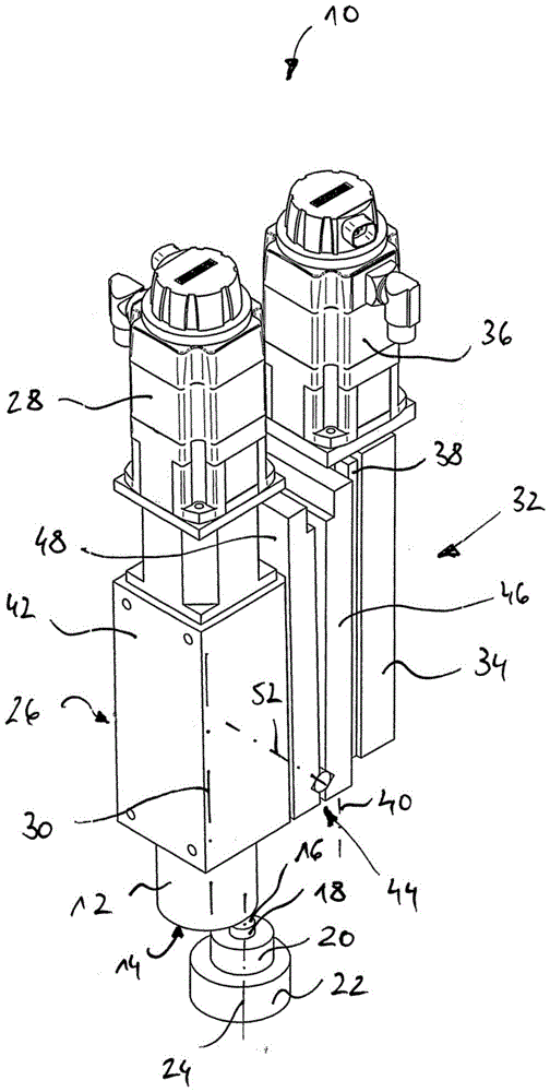
图1示出了用于精加工工件的装置的实施例的立体图;Figure 1 shows a perspective view of an embodiment of an apparatus for finishing a workpiece;
图2示出了图1的装置的侧视图,其中,装置的工具芯轴位于初始位置;以及FIG. 2 shows a side view of the device of FIG. 1 with the tool mandrel of the device in an initial position; and
图3示出了类似于图2的侧视图,其中,工具芯轴位于相对于初始位置倾斜的运行位置。Figure 3 shows a side view similar to Figure 2 with the tool mandrel in an operating position inclined relative to the initial position.
具体实施方式Detailed ways
在附图中,用于精加工工件的装置在整体上由附图标记10表示。装置10包括精加工工具12,精加工工具12例如被设计成具有杯形砂轮的形式。杯形砂轮在其端面上具有环形作用面14,利用该作用面能够对工件18的平坦的或者球形的表面16进行加工。In the figures, the device for finishing a workpiece is indicated in its entirety by the
工件18被容纳在工件保持件20(例如,夹盘)中。驱动工件18以围绕驱动轴线24旋转的方式被工件驱动装置22驱动。The
工具12被保持在工具芯轴26上,并且以围绕芯轴轴线30旋转的方式被驱动装置28驱动。芯轴轴线30和工件18的驱动轴线24基本上彼此平行地延伸或者以数度(例如,最大5°)相对彼此倾斜。The
为了能够在工件18的方向上递送工具12的作用面14以及再次离开,设置了在整体上由附图标记32表示的递送装置。递送装置32包括承载件34,承载件34连接到驱动装置36,且驱动装置36对滑座38进行作用。滑座38能够通过驱动装置36沿递送轴线40偏移。递送轴线40相对于芯轴轴线30平行地或者至少基本平行地(例如,最大以5°倾斜)延伸。递送装置32也用于产生挤压力,精加工工具12的作用面14以该挤压力被挤压到工件18的表面16上。In order to be able to deliver the
一方面为了连接递送装置32的滑座38以及另一方面连接工具芯轴26的壳体42,装置10包括在整体上由标记44表示的连接装置。For connecting the
连接装置44包括两个能够相对彼此运动的平板体形部件46和48。第一部件46特别以螺栓连接的方式连接到递送装置32的滑座38。第二部件48特别以螺栓连接的方式连接到工具芯轴26的壳体42。The connecting
为了连接部件46和48,设置有枢转轴承50,枢转轴承50定义了枢转轴线52。枢转轴线52具有相对于工具芯轴26的芯轴轴线30的间距54。在附图中仅示意性地示出枢转轴承50。例如按照常规的方式,枢转轴承包括枢转销和包围枢转销的轴套。To connect the
部件46和48之间的枢转销连接部件46和48,使得它们仅能够以单一自由度相对于彼此运动。因此,部件46和48仅能够围绕枢转轴线52相对于彼此枢转。有利的是,枢转轴线52位于部件46和48的相邻于工具12的端部上。A pivot pin between the
为了阻止部件46和48之间的枢转,连接装置44包括连接区域54,连接区域54作为连接装置44的传导力的组件起作用。在连接区域54中仅传递拉伸力和压缩力。在连接区域54中,在部件46和48之间作用的连接力通过力测量装置56传递。力测量装置56例如可以由测力计形成。In order to prevent pivoting between the
在连接区域54中,力测量装置56沿着力传递轴线58传递拉伸力和压缩力。In the connection region 54 , the
特别地,力测量装置56仅沿着力传递轴线58传递压缩力。在此情况下,有利的是,力测量装置56包括能够彼此相对运动的两个部件,这两个部件通过弹簧相对彼此偏置并且通过传感器单元彼此间隔开。通过这种方式,部件46和48能够相对彼此无间隙地定位。In particular, the
力传递轴线58相对于枢转轴线52成角度地,特别是垂直地或者至少基本上垂直地布置,并且相对于枢转轴线52具有间距60。The force transmission axis 58 is arranged at an angle relative to the
在连接区域54中布置有机械地与力测量装置串联地布置的间距调节装置62。间距调节装置62包括例如调节轴64,调节轴64在一端处连接到部件46和48中的一个,并且在另一端处连接到力测量装置56。为了固定间距调节装置62,可以设置有调节螺母66。A
间距调节装置62允许对部件46和48之间的沿着力传递轴线58测量的间距进行调节。通过将力传递轴线58相对于枢转轴线52间隔开,部件46和48之间的沿着力传递轴线存在的间距的变化导致部件46和48围绕枢转轴线52的彼此相对枢转,参见图2和3。通过这种方式,能够调节芯轴轴线30的倾斜角。例如,轴线24和30能够彼此平行地延伸(参见图2);或者轴线24和30彼此相对倾斜地延伸(参见图3)。The
在工件18的精加工期间,工件18围绕轴线24旋转。同时,工具12围绕芯轴轴线30旋转。工具12的作用面14与工件18的工件面16啮合。由于为了精加工工件18而将工具12的压缩力施加到工件18上,所以工具12承受一个相应的挤压力,该挤压力在图2中由附图标记62表示。挤压力62通过“杠杆臂”54影响对工具芯轴26作用的围绕枢转轴线52的转矩(与在图2中的图示相对应地,该转矩在顺时针的方向上围绕枢转轴线52延伸)。During finishing of the
利用“杠杆臂”60相对于枢转轴线52间隔开的力测量装置56将相反的转矩施加到工具芯轴26上,从而使其相对于枢转轴线52静止。相反的转矩等于由力测量装置56沿着力传递轴线58测量的处理力(对应于由第二部件48施加到力测量装置上的压缩力的反作用力)和“杠杆臂”60的长度的乘积。An opposing torque is applied to the
相应地,挤压力62等于由力测量装置56测量的处理力和杠杆臂因数(间距60除以间距54)的乘积。Accordingly, the squeezing
Claims (7)
Applications Claiming Priority (2)
| Application Number | Priority Date | Filing Date | Title |
|---|---|---|---|
| DE102015217600.2 | 2015-09-15 | ||
| DE102015217600.2A DE102015217600B4 (en) | 2015-09-15 | 2015-09-15 | Device for finishing workpieces |
Publications (2)
| Publication Number | Publication Date |
|---|---|
| CN106938441A CN106938441A (en) | 2017-07-11 |
| CN106938441B true CN106938441B (en) | 2020-09-15 |
Family
ID=58160545
Family Applications (1)
| Application Number | Title | Priority Date | Filing Date |
|---|---|---|---|
| CN201610826094.7A Expired - Fee Related CN106938441B (en) | 2015-09-15 | 2016-09-14 | Device for finishing a workpiece |
Country Status (2)
| Country | Link |
|---|---|
| CN (1) | CN106938441B (en) |
| DE (1) | DE102015217600B4 (en) |
Citations (8)
| Publication number | Priority date | Publication date | Assignee | Title |
|---|---|---|---|---|
| DE4005399C1 (en) * | 1990-02-21 | 1991-04-11 | Bernhard Dr.-Ing. 4782 Erwitte De Juergenhake | Ensuring connection quality of crimped tags - comparing electrical connection with predetermined value and finishing processing only if within tolerance range |
| DE69009890T2 (en) * | 1989-02-23 | 1994-09-22 | Supfina Maschf Hentzen | METHOD AND DEVICE FOR FINISHING AND SUPFINING. |
| JPH09234524A (en) * | 1996-02-29 | 1997-09-09 | Nisshinbo Ind Inc | Method for controlling setting condition of work in pipe working machine |
| DE202006017265U1 (en) * | 2006-11-11 | 2007-01-18 | Thielenhaus Technologies Gmbh | Support for tool spindle has two sections joined by one-piece, elastically deformable bridges that enable relative movement between sections in at least one direction of plane and that are stiff perpendicular to plane |
| DE102007024760A1 (en) * | 2007-05-26 | 2008-07-17 | Thielenhaus Technologies Gmbh | Method for fine grinding of inner surfaces of roller bearing rings, involves determining contact of the cup wheel on workpiece by workpiece power sensors and measurement signals of sensors applied |
| CN102248476A (en) * | 2010-03-09 | 2011-11-23 | 纳格尔机械及工具制造厂有限责任公司 | Method and apparatus for the measurement-aided fine machining of workpiece surfaces, and measuring system |
| CN103213067A (en) * | 2012-01-23 | 2013-07-24 | 德国索菲纳有限公司 | Finishing device for finishing a workpiece |
| CN104842697A (en) * | 2015-05-29 | 2015-08-19 | 福建省天大精诺信息有限公司 | Single-pillar rough and finish machining integrated machine |
Family Cites Families (4)
| Publication number | Priority date | Publication date | Assignee | Title |
|---|---|---|---|---|
| DE3112991C2 (en) * | 1981-04-01 | 1985-12-12 | Hoesch Ag, 4600 Dortmund | Cylindrical grinding machine for the controlled grinding of cracks on rollers |
| DE10201639A1 (en) | 2002-01-17 | 2003-07-31 | Thielenhaus Ernst Gmbh & Co Kg | Process for finishing workpieces |
| JP4098761B2 (en) * | 2004-08-17 | 2008-06-11 | ファナック株式会社 | Finishing method |
| US7645180B2 (en) * | 2007-10-18 | 2010-01-12 | Thielenhaus Microfinish Corporation | Method for finishing a workpiece |
-
2015
- 2015-09-15 DE DE102015217600.2A patent/DE102015217600B4/en not_active Expired - Fee Related
-
2016
- 2016-09-14 CN CN201610826094.7A patent/CN106938441B/en not_active Expired - Fee Related
Patent Citations (8)
| Publication number | Priority date | Publication date | Assignee | Title |
|---|---|---|---|---|
| DE69009890T2 (en) * | 1989-02-23 | 1994-09-22 | Supfina Maschf Hentzen | METHOD AND DEVICE FOR FINISHING AND SUPFINING. |
| DE4005399C1 (en) * | 1990-02-21 | 1991-04-11 | Bernhard Dr.-Ing. 4782 Erwitte De Juergenhake | Ensuring connection quality of crimped tags - comparing electrical connection with predetermined value and finishing processing only if within tolerance range |
| JPH09234524A (en) * | 1996-02-29 | 1997-09-09 | Nisshinbo Ind Inc | Method for controlling setting condition of work in pipe working machine |
| DE202006017265U1 (en) * | 2006-11-11 | 2007-01-18 | Thielenhaus Technologies Gmbh | Support for tool spindle has two sections joined by one-piece, elastically deformable bridges that enable relative movement between sections in at least one direction of plane and that are stiff perpendicular to plane |
| DE102007024760A1 (en) * | 2007-05-26 | 2008-07-17 | Thielenhaus Technologies Gmbh | Method for fine grinding of inner surfaces of roller bearing rings, involves determining contact of the cup wheel on workpiece by workpiece power sensors and measurement signals of sensors applied |
| CN102248476A (en) * | 2010-03-09 | 2011-11-23 | 纳格尔机械及工具制造厂有限责任公司 | Method and apparatus for the measurement-aided fine machining of workpiece surfaces, and measuring system |
| CN103213067A (en) * | 2012-01-23 | 2013-07-24 | 德国索菲纳有限公司 | Finishing device for finishing a workpiece |
| CN104842697A (en) * | 2015-05-29 | 2015-08-19 | 福建省天大精诺信息有限公司 | Single-pillar rough and finish machining integrated machine |
Also Published As
| Publication number | Publication date |
|---|---|
| CN106938441A (en) | 2017-07-11 |
| DE102015217600A1 (en) | 2017-03-16 |
| DE102015217600B4 (en) | 2020-02-20 |
Similar Documents
| Publication | Publication Date | Title |
|---|---|---|
| US9303968B2 (en) | Lever type measuring machine | |
| US6953383B2 (en) | Method of determining current position data of a machining tool and apparatus therefor | |
| US8157271B2 (en) | Floating chuck mechanism | |
| JP2010531239A (en) | Gripper for manipulator robot with improved gripping accuracy, and manipulator robot provided with at least one gripper | |
| KR20150127979A (en) | The seat of the ball joint ball and the clearance inspection apparatus | |
| JPH08150555A (en) | A device that processes the cylindrical shaft while adjusting the diameter with a polishing belt. | |
| CN104385058B (en) | Device and method for rapid detection of static stiffness of CNC machine tools | |
| JP7165071B2 (en) | Honing machine | |
| CN103459072A (en) | Centering method for optical elements | |
| JP2013233651A (en) | Pressing force detection device for grinder | |
| KR20060133060A (en) | Manual grinding tool | |
| CN106938441B (en) | Device for finishing a workpiece | |
| TW200941569A (en) | Machining quality judging method for wafer grinding machine and wafer grinding machine | |
| US11121113B2 (en) | Bonding apparatus incorporating variable force distribution | |
| JP2823493B2 (en) | Method and apparatus for detecting blade deflection of slicing device and blade deflection control device | |
| JPH1190822A (en) | Workrest device | |
| US1193686A (en) | Botative vibbatoby testing-machine | |
| CN112284602A (en) | A high-precision clamping force measuring device | |
| US5201617A (en) | Apparatus for supporting a machine tool on a robot arm | |
| JP6207275B2 (en) | Component manufacturing method, polishing apparatus, optical member manufacturing method, and mold manufacturing method | |
| JP6274769B2 (en) | Part manufacturing method and polishing apparatus | |
| JP3992388B2 (en) | Lens centering machine and lens centering device | |
| JP5192510B2 (en) | Rotation angle measurement device and rotation angle measurement method for rotation device | |
| JP5344290B2 (en) | Polishing equipment | |
| JPS59152062A (en) | Dressing device for regulating emery wheel |
Legal Events
| Date | Code | Title | Description |
|---|---|---|---|
| PB01 | Publication | ||
| PB01 | Publication | ||
| SE01 | Entry into force of request for substantive examination | ||
| SE01 | Entry into force of request for substantive examination | ||
| GR01 | Patent grant | ||
| GR01 | Patent grant | ||
| CF01 | Termination of patent right due to non-payment of annual fee | ||
| CF01 | Termination of patent right due to non-payment of annual fee |
Granted publication date: 20200915 |