System and method for reducing fuel consumption in a vehicle
Cross Reference to Related Applications
This application is a partial continuation of U.S. application No.14/094333 filed on 12/2/2013, claiming priority of U.S. provisional application No.61/732312 filed on 12/1/2012, both of which are incorporated herein by reference in their entirety.
Technical Field
Embodiments of the invention relate generally to vehicle control. Certain embodiments relate to systems and methods for reducing fuel consumption in a vehicle in a dynamic braking mode of operation.
Background
In the mining industry, large off-highway vehicles "OHVs" typically employ electrically powered wheels for propelling or decelerating the vehicle. In particular, OHVs typically include a high horsepower diesel engine in combination with an alternator, a traction inverter, and a wheel drive assembly housed within the rear tires of the vehicle. In operation, the diesel engine drives an alternator, which powers the traction inverter. The traction inverter includes semiconductor power switches that commutate the alternator output current to provide electrical power to an electric drive motor, such as an AC traction motor, of the wheel drive assembly, which converts the electrical power back to mechanical power to drive the wheels and propel the vehicle.
As understood in the art, the traction motors provide traction power to propel the vehicle. The traction motor is also configured to provide a braking force for controlling speed or for decelerating the vehicle. This is generally referred to as dynamic braking. Simply stated, when the traction motor is not required to provide motive force, it can be reconfigured so that the motor operates as a power generator. So configured, the traction motor generates electrical energy having the effect of decelerating the vehicle. In certain vehicles and systems, electrical energy is stored in a battery for later use or, more generally, dissipated via a speed reduction grid. Specifically, some vehicles and systems are configured to store electrical energy provided by the motor during dynamic braking in an energy storage device or battery for later use. This stored energy is used to power auxiliary devices and/or drive motors during a propulsion mode or idle (idling) of operation in order to minimize engine engagement and reduce fuel consumption.
An advantageous alternative to the storage arrangement is to waste only energy in the form of heat via the dynamic braking deceleration grid of the resistor and insulator. However, a disadvantage of this alternative is that the grid cooling system with an electrically driven blower is often necessary to help dissipate heat from the grid, which increases power requirements and thus fuel consumption.
The engine continues to consume fuel to meet the electrical demand and auxiliary loads of the vehicle even during dynamic braking. For example, this includes powering traction motor blowers, radiator fans, alternator blowers for operating room heaters or air conditioners, hydraulic pumps, and the like. In the case of an OHV, this includes powering cooling fans to cool all components in the traction drive system.
In view of the above, there is a need for a system and method that reduces fuel consumption during a dynamic braking mode of operation by recovering dynamic braking energy and improves the overall efficiency of an electric drive machine.
Disclosure of Invention
In an embodiment, a drive system for a vehicle includes: an engine; an alternator coupled to the engine; and a traction motor system. The alternator is configured to supply power to at least one auxiliary load. The traction motor system is operatively coupled with drive wheels of the vehicle and is configured for receiving primary electric power from the alternator and for propelling the vehicle in response to the primary electric power. The drive system further includes a motor electrically connected with the traction motor system and mechanically coupled with the engine. The motor is configured to receive electrical power from the traction motor system in a dynamic braking mode of operation of the traction motor system and to transfer power to the engine during the dynamic braking mode.
In another embodiment, a drive system for a vehicle includes: an engine; an alternator coupled to the engine; and a traction motor system. The alternator is configured to supply power to at least one auxiliary load. The traction motor system is operatively coupled with drive wheels of the vehicle and is configured for receiving primary electric power from the alternator and for propelling the vehicle in response to the primary electric power. The drive system further includes a three-phase inverter/rectifier electrically connected to the traction motor system and the alternator. The inverter/rectifier is configured to receive electrical power from the traction motor system and feed the electrical power as torque to the alternator in order to reduce engine load in a dynamic braking mode of operation of the traction motor system.
In yet another embodiment, a method is provided. The method comprises the following steps: generating primary electric power at an alternator connected with the engine; operating a traction motor coupled in driving relationship with a wheel of the vehicle to propel the vehicle during a propulsion mode of operation and generating electrical power during a dynamic braking mode of operation, wherein in the propulsion mode of operation primary electrical power is transmitted to the traction motor to power the motor; and offsetting the auxiliary engine load using the power generated during the dynamic braking mode of operation in order to reduce fuel consumption of the vehicle (e.g., as compared to an operating mode in which the power generated during dynamic braking is not used to offset the auxiliary engine load).
The invention provides a group of technical schemes, which are as follows:
1. a drive system for a vehicle, comprising:
an engine;
an alternator coupled to the engine, the alternator configured to power at least one auxiliary load;
a traction motor system operatively coupled with drive wheels of the vehicle, the traction motor system configured to receive primary electric power from the alternator and to propel the vehicle in response to the primary electric power; and
a motor electrically connected with the traction motor system and mechanically coupled with the engine, the motor configured to receive electrical power from the traction motor system in a dynamic braking mode of operation of the traction motor system and to transfer power to the engine during the dynamic braking mode.
2. The drive system according to claim 1, wherein:
the at least one auxiliary load includes at least one of a hydraulic pump or control and a motor cooling fan.
3. The drive system according to claim 1, wherein:
the motor is a DC motor.
4. The drive system according to claim 3, wherein:
the motor is mechanically coupled to the engine by a variable torque coupling.
5. The drive system according to claim 4, wherein:
the variable torque coupling includes at least one of a belt, chain, gear, or hydraulic coupling.
6. The drive system according to claim 3, wherein:
the motor is mechanically coupled to the engine by a direct mechanical coupling.
7. The drive system according to claim 1, wherein:
the motor is an AC motor; and
wherein the system further includes an inverter residing in the traction motor system for converting DC electrical power from the traction motor system to AC electrical power for use by the AC motor.
8. The drive system according to claim 7, further comprising:
a clutch assembly connected with the AC motor and the engine, the clutch assembly configured to selectively alter a magnitude of torque provided to the engine.
9. The drive system according to claim 7, further comprising:
at least one blower motor electrically coupled with the traction drive system; and
at least one blower mechanically coupled with the blower motor;
wherein the blower motor is configured to receive electrical power from the traction motor system and drive the blower to provide cooling to the traction motor system in the dynamic braking mode of operation of the traction motor system.
10. The drive system according to claim 9, wherein:
the at least one blower motor is a pair of blower motors; and
the at least one blower is a pair of blowers.
11. The drive system according to claim 9, wherein:
the blower motor is electrically coupled to the traction motor system through an H-bridge.
12. The drive system according to claim 9, further comprising:
a battery electrically connected with the traction motor system and the alternator;
wherein the battery is configured to receive electrical power from the traction motor system to recharge the battery and supply stored electrical power to the alternator to crank the engine in the dynamic braking mode of operation of the traction motor system.
13. The drive system according to claim 12, further comprising:
a chopper intermediate the battery and the alternator, the chopper configured for field excitation of the alternator during engine cranking.
14. The drive system according to claim 1, wherein:
the vehicle is an off-highway vehicle.
15. A drive system for a vehicle, comprising:
an engine;
an alternator coupled to the engine, the alternator configured to power at least one auxiliary load;
a traction motor system operatively coupled with drive wheels of the vehicle, the traction motor system configured to receive primary electric power from the alternator and to propel the vehicle in response to the primary electric power; and
a three-phase inverter/rectifier electrically connected with the traction motor system and the alternator, the inverter/rectifier configured to receive electrical power from the traction motor system and feed the electrical power as torque to the alternator in a dynamic braking mode of operation of the traction motor system to reduce engine load.
16. The drive system according to claim 15, further comprising:
a battery electrically connected with the traction motor system and the alternator;
wherein the battery is configured to receive electrical power from the traction motor system to recharge the battery and supply stored electrical power to the alternator to crank the engine in the dynamic braking mode of operation of the traction motor system.
17. The drive system according to claim 16, further comprising:
a chopper intermediate the battery and the alternator, the chopper configured for field excitation of the alternator during engine cranking.
18. The drive system according to claim 15, further comprising:
at least one blower motor electrically coupled with the traction drive system; and
at least one blower mechanically coupled with the blower motor;
wherein the blower motor is configured to receive electrical power from the traction motor system and drive the blower to provide cooling to the traction motor system in the dynamic braking mode of operation of the traction motor system.
19. The drive system according to claim 18, wherein:
the at least one blower motor is a pair of blower motors; and
the at least one blower is a pair of blowers.
20. The drive system according to claim 18, wherein:
the blower motor is electrically coupled to the traction motor system through an H-bridge.
21. A method comprising the steps of:
generating primary electric power at an alternator connected with the engine;
operating a traction motor coupled in driving relationship with a wheel of a vehicle to propel the vehicle during a propulsion mode of operation and generate electrical power during a dynamic braking mode of operation, wherein in the propulsion mode of operation the primary electrical power is transmitted to the traction motor to power the motor; and
offsetting an auxiliary engine load to reduce fuel consumption of the vehicle using the electrical power generated during the dynamic braking mode of operation.
22. The method of claim 21, further comprising the steps of:
powering a motor mechanically coupled to the engine with the electrical power generated during the dynamic braking mode of operation, the motor configured to transfer power to the engine.
23. The method of claim 22, wherein:
the motor is a DC motor; and
the motor is mechanically coupled to the engine by a variable torque coupling.
24. The method of claim 22, wherein:
the motor is an AC motor; and
wherein the method further comprises the steps of: converting the electrical power generated during the dynamic braking mode of operation into AC electrical power for use by the AC motor.
25. The method of claim 24, further comprising the steps of:
operating a clutch assembly connected with the AC motor and the engine to alter a magnitude of torque provided to the engine.
26. The method of claim 25, further comprising the steps of:
powering a blower motor connected to a blower configured to provide cooling for the traction motor using the power generated during the dynamic braking mode of operation.
27. The method of claim 25, further comprising the steps of:
recharging a battery of the vehicle with the power generated during the dynamic braking mode of operation.
28. The method of claim 27, wherein:
the battery is electrically connected with the alternator; and
the method further comprises the steps of: supplying the stored electric power from the battery to the alternator to crank the engine during starting.
29. The method of claim 21, further comprising the steps of:
at an inverter/rectifier, the electrical power generated during the dynamic braking mode of operation is received and supplied to the alternator to produce torque at the alternator.
30. The method of claim 21, wherein:
the auxiliary engine load includes at least one of a hydraulic pump or control and a motor cooling fan.
The invention provides another technical scheme, which comprises the following steps:
1. a drive system for a vehicle, comprising:
an engine;
an alternator coupled to the engine, the alternator configured to power at least one auxiliary load;
a traction motor system operatively coupled with drive wheels of the vehicle, the traction motor system configured to receive primary electric power from the alternator and to propel the vehicle in response to the primary electric power; and
a motor electrically connected with the traction motor system and mechanically coupled with the engine, the motor configured to receive electrical power from the traction motor system in a dynamic braking mode of operation of the traction motor system and to transfer power to the engine during the dynamic braking mode.
2. The drive system according to claim 1, wherein:
the motor is a DC motor.
3. The drive system according to claim 2, wherein:
the motor is mechanically coupled with the engine through a variable torque coupling comprising at least one of a belt, chain, gear, or hydraulic coupling.
4. The drive system according to claim 2, wherein:
the motor is mechanically coupled to the engine by a direct mechanical coupling.
5. The drive system according to claim 1, wherein:
the motor is an AC motor; and
wherein the system further includes an inverter residing in the traction motor system for converting DC electrical power from the traction motor system to AC electrical power for use by the AC motor.
6. The drive system according to claim 5, further comprising:
a clutch assembly connected with the AC motor and the engine, the clutch assembly configured to selectively alter a magnitude of torque provided to the engine.
7. The drive system according to claim 5, further comprising:
at least one blower motor electrically coupled with the traction drive system; and
at least one blower mechanically coupled with the blower motor;
wherein the blower motor is configured to receive electrical power from the traction motor system and drive the blower to provide cooling to the traction motor system in the dynamic braking mode of operation of the traction motor system.
8. The drive system according to claim 7, wherein:
the at least one blower motor is a pair of blower motors; and
the at least one blower is a pair of blowers.
9. The drive system according to claim 7, wherein:
the blower motor is electrically coupled to the traction motor system through an H-bridge.
10. The drive system according to claim 7, further comprising:
a battery electrically connected with the traction motor system and the alternator; and
a chopper intermediate the battery and the alternator, the chopper configured for field excitation of the alternator during engine cranking;
wherein the battery is configured to receive electrical power from the traction motor system to recharge the battery and supply stored electrical power to the alternator to crank the engine in the dynamic braking mode of operation of the traction motor system.
11. A drive system for a vehicle, comprising:
an engine;
an alternator coupled to the engine, the alternator configured to power at least one auxiliary load;
a traction motor system operatively coupled with drive wheels of the vehicle, the traction motor system configured to receive primary electric power from the alternator and to propel the vehicle in response to the primary electric power; and
a three-phase inverter/rectifier electrically connected with the traction motor system and the alternator, the inverter/rectifier configured to receive electrical power from the traction motor system and feed the electrical power as torque to the alternator in a dynamic braking mode of operation of the traction motor system to reduce engine load.
12. The drive system according to claim 11, further comprising:
a battery electrically connected with the traction motor system and the alternator; and
a chopper intermediate the battery and the alternator, the chopper configured for field excitation of the alternator during engine cranking;
wherein the battery is configured to receive electrical power from the traction motor system to recharge the battery and supply stored electrical power to the alternator to crank the engine in the dynamic braking mode of operation of the traction motor system.
13. The drive system according to claim 11, further comprising:
at least one blower motor electrically coupled with the traction drive system; and
at least one blower mechanically coupled with the blower motor;
wherein the blower motor is configured to receive electrical power from the traction motor system and drive the blower to provide cooling to the traction motor system in the dynamic braking mode of operation of the traction motor system.
14. The drive system according to claim 13, wherein:
the at least one blower motor is a pair of blower motors; and
the at least one blower is a pair of blowers.
15. The drive system according to claim 13, wherein:
the blower motor is electrically coupled to the traction motor system through an H-bridge.
Drawings
The invention will be better understood from reading the following description of non-limiting embodiments with reference to the attached drawings, in which:
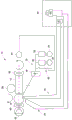
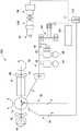
FIG. 1 is a simplified schematic diagram of a system for reducing fuel consumption in a vehicle according to an embodiment of the present invention;
FIG. 2 is a simplified schematic diagram of a system for reducing fuel consumption in a vehicle according to another embodiment of the present invention;
FIG. 3 is a simplified schematic diagram of a system for reducing fuel consumption in a vehicle according to another embodiment of the present invention;
FIG. 4 is a simplified schematic diagram of a system for reducing fuel consumption in a vehicle according to another embodiment of the present invention;
FIG. 5 is a simplified schematic diagram of a system for reducing fuel consumption in a vehicle according to another embodiment of the present invention.
Detailed Description
In the following, reference will be made in detail to exemplary embodiments of the invention, examples of which are illustrated in the accompanying drawings. Wherever possible, the same reference characters will be used throughout the drawings to refer to the same or like parts. Although embodiments of the present invention are suitable for use with both mobile implementations and fixed implementations, for ease of explanation, the mobile implementations are described in detail herein. More specifically, for clarity of illustration, an OHV was chosen for the disclosure of the mobile embodiment. Other suitable vehicles include, for example, on-road vehicles, locomotives, construction equipment, industrial equipment, and marine vessels. As used herein, "in electrical communication" or "electrically coupled" means that certain components are configured to communicate with each other through direct or indirect signaling via direct or indirect electrical connections. As used herein, "mechanically coupled" refers to any coupling method capable of supporting the necessary force for transmitting torque between components. As used herein, "operatively coupled" means connected, whether directly or indirectly, that may be. The connection need not be a mechanical attachment.
Fig. 1 schematically illustrates an exemplary drive system 10 for an electric drive machine, such as an OHV or other vehicle. The drive system 10 includes a primary power source, such as an engine 12 (e.g., diesel engine, gasoline engine, multi-fuel engine, etc.) and a traction alternator/generator 14, the traction alternator/generator 14 being mechanically coupled to the engine 12 and driven by the engine 12. As illustrated in fig. 1, the traction alternator 14 is electrically coupled with the traction bus 16. The alternator 14 is configured to provide AC electrical power to one or more rectifiers 18, the rectifiers 18 being electrically connected with one or more power converters, such as first and second inverters 20, 22, via the traction bus 16. The inverters 20, 22 are connected to first and second traction motors 24, 26 associated with first and second wheels of the vehicle, respectively. As is known in the art, the rectifier 18 is configured to convert AC power received from the alternator 14 to a DC output, which is then fed through the traction bus 16 to the inverters 20, 22. The inverters 20, 22 are configured to supply three-phase variable frequency AC power to first and second traction motors 24, 26 associated with first and second wheels of the vehicle (typically rear wheels of the vehicle). Although the rectifier 18 is illustrated as being separate from the traction alternator 14, in certain embodiments the rectifier may form part of the alternator, as is known in the art. In an embodiment, the traction bus 16 is a 1000-1500V DC bus.
As also shown in fig. 1, in an embodiment, a starter motor 28 may be associated with the engine 12 for rotating the engine 12, as is known in the art, in order to initiate operation. Additionally, the vehicle may include a battery 30, such as a 24V battery, the battery 30 being electrically coupled to the alternator 14 through a third winding 32 and a field winding 34. The battery 30 is configured to function as a field static exciter of the alternator to initiate operation of the electric drive system of the vehicle.
The traction motors 24, 26 provide traction power to move the vehicle and may be AC or DC electric motors. When a DC traction motor is used, the output of the alternator is typically rectified to provide the appropriate DC power. When using AC traction motors, the alternator output is typically rectified to DC prior to being supplied to the traction motors 24, 26, and thereafter inverted to three-phase AC. During the propulsion mode of operation, power may be transferred from the engine 12 to the traction motors 24, 26, and thus to the wheels of the vehicle, to effect movement.
In addition to providing motive power, the traction motors 24, 26 also provide braking force for controlling the speed of the vehicle on which the drive system 10 is deployed. This is generally referred to as dynamic braking. During a dynamic braking mode of operation, such as when the motion of the vehicle is to be decelerated, power may be generated by driving mechanical rotation of the wheels and directed to the deceleration grid 36. In particular, the kinetic energy of the vehicle may be converted into rotational power at the driving wheels. Rotation of the drive wheels may further rotate the motors 24, 26 to generate electrical power, for example in the form of AC power. The inverters 20, 22 may act as a bridge to convert the power supplied by the motors 24, 26 into DC power. Dissipation of the DC power generated by the motors 24, 26 may produce a counter-rotating torque at the driven wheels to decelerate the vehicle. As shown, this dissipation may be accomplished by passing the generated current provided by the inverters 20, 22 through a resistor such as a dynamic braking grid 36 or a deceleration grid.
As further illustrated in fig. 1, the drive system 10 also includes an engine radiator fan 38, the engine radiator fan 38 being driven by the engine 12 to provide cooling to the engine 12. The system 10 may also include one or more control and motor cooling fans 40, the control and motor cooling fans 40 being mechanically coupled to the alternator 14. One or more cooling fans 40 are configured to provide cooling for all components of the traction drive system, such as inverters 20, 22, traction motors 24, 26, and the like. The traction alternator 14 may also be coupled with a hydraulic pump 42, the hydraulic pump 42 providing hydraulic pressure for use by accessories or other components of the vehicle. That is, in addition to providing electrical power to the traction bus 16 to enable operation of the traction motors 24, 26 to propel the vehicle, the alternator 14 also provides electrical power to other components, such as hydraulic pumps and cooling fans, via power from the engine 12. As will be readily appreciated, therefore, even in the dynamic braking mode of operation, these components require power from the engine 12, which generally increases fuel consumption and reduces the efficiency of the vehicle. At maximum deceleration/dynamic braking, only 200 horsepower may be required to power the auxiliary loads for cooling and hydraulics on a hot day.
In an embodiment, the system 10 is configured to recover dynamic braking energy when in a dynamic braking mode of operation, and use this recovered energy to offset engine loads (e.g., from the hydraulic pump 42, one or more controls, and the motor cooling fan 40, etc.) in order to reduce fuel consumption as compared to prior systems. Specifically, as illustrated in fig. 1, the drive system 10 includes a DC electric motor 44, the DC electric motor 44 being electrically coupled with the dynamic braking grids 36, and mechanically coupled with the engine 12. In an embodiment, the motor 44 is mechanically coupled with the engine through a variable torque type coupling, although a direct mechanical coupling may alternatively be employed. In embodiments, the coupling may comprise at least one of a belt, chain, gear or hydraulic coupling.
Thus, the DC motor 44 is configured to receive DC electrical power from the dynamic braking grids 36 during a dynamic braking mode of operation of the vehicle. Specifically, the motor 44 utilizes DC electrical power from dynamic braking to generate a mechanical output that is used to assist in driving the engine 12 and accelerating the engine 12. In this way, the motor 44 can be utilized to 'offset' auxiliary engine loads, such as cooling fan loads and hydraulic pump loads, during the dynamic braking mode of operation, thereby reducing fuel consumption as compared to prior systems that relied solely on the engine to provide auxiliary power.
Referring now to fig. 2, a drive system 100 for a vehicle according to another embodiment of the present invention is illustrated. Drive system 100 is generally similar in operation and configuration to drive system 10 described above in connection with fig. 1 (i.e., it is operable in both a propulsion mode and a dynamic braking mode of operation), wherein like reference numerals refer to like parts. However, rather than providing DC electrical power from the dynamic braking grids to a DC motor connected to the engine 12 to help accelerate the engine 12 to help assist the auxiliary engine load, the system 100 is configured to transfer power generated during dynamic braking directly from the traction link/bus 16 to the alternator 14 to substantially cancel the auxiliary load on the engine 12.
As shown in fig. 2, the drive system 100 includes a three-phase inverter/rectifier 102, the three-phase inverter/rectifier 102 electrically coupled with the dynamic braking grids 36 of the traction link/bus 16 through a double isolated leg 104 of power feedback. The three-phase inverter/rectifier 102 is in turn electrically coupled to the traction alternator 14. Thus, the three-phase inverter/rectifier 102 allows power recaptured from dynamic braking to be fed back as torque through the alternator 14 to reduce engine load. Specifically, the use of the three-phase inverter/rectifier 102 essentially renders the third winding 32 an all three-phase machine.
As also illustrated in fig. 2, the system 100 further includes a primary H-bridge 106 and a secondary battery-side H-bridge 108 that are used to connect the battery 30 with both the dynamic braking grid 36 and the inverter/rectifier 102. As illustrated, the battery 30 is electrically coupled with the dynamic braking grids 36 of the traction bus 16 through the dual isolated branches 104 of the power feedback. This configuration facilitates charging of the battery 30 (i.e., energy flow from the dynamic braking grids 36 to the battery 30) with dynamic braking energy when the vehicle is operating in the dynamic braking mode. It also allows power to be transferred from the battery 30 (through the inverter/rectifier 102) to the alternator 14 to ensure a sufficient voltage for cranking the engine 12 during start-up. Specifically, the charging of the battery 30 can be utilized as a boost converter for bringing the low voltage DC battery up to the voltage required for engine cranking through the alternator low voltage winding. In connection with this, system 100 also includes a chopper 110 intermediate inverter/rectifier 102 and primary H-bridge 108. A chopper 110 is utilized for field excitation of the alternator 14 during engine cranking. Thus, this configuration eliminates the need to start the engine 12 with a separate starter motor.
In an embodiment, each dynamic braking grid may have a capability of 1MW of power, so that evenly split branches will allow approximately 300KW to be fed back through alternator 14 as torque in order to reduce engine load in the slow down/dynamic braking mode. Thus, the drive system 100 can provide many advantages. First, by applying torque into the alternator 14, the load on the engine (such as the cooling fan 40 and the hydraulic pump 42) can be substantially eliminated. Specifically, rather than the engine 12 having to supply sufficient power to meet auxiliary load demands, torque derived from dynamic braking is utilized to help drive the alternator 14 to help meet such demands. Thus, since the engine 12 is not solely responsible for driving the alternator 14, fuel consumption by the engine can be reduced, at least during dynamic braking. In addition to utilizing the power generated during dynamic braking to provide torque into the alternator, the power from dynamic braking can be utilized to charge the truck battery 30, which can then be utilized in conjunction with the chopper 110 to crank and start the engine. As discussed above, this eliminates the need to employ a separate starter motor to start the engine 12.
Turning now to fig. 3, a drive system 200 for a vehicle according to another embodiment of the present invention is illustrated. Drive system 200 is generally similar in operation and configuration to drive system 10 and drive system 100 described above in connection with fig. 1 and 2 (i.e., it is operable in both a propulsion mode and a dynamic braking mode of operation, wherein like reference numerals refer to like parts).
As shown therein, the drive system 200 includes a primary H-bridge 202 and a secondary H-bridge 204 electrically coupled with the traction bus 16. The secondary H-bridge 204 is electrically coupled to a pair of inverters, such as a third inverter 206 and a fourth inverter 208. The inverters 206, 208 are electrically coupled to third and fourth AC motors 210, 212, respectively, the third and fourth AC motors 210, 212 being associated with first and second blowers 214, 216 and configured to drive the first and second blowers 214, 216. In an embodiment, the first blower 214 is configured to provide cooling for at least one of the inverters 20, 22, 206, 208 and/or the rectifier 18, and the second blower 216 is configured to provide cooling for at least one of the motors 24, 26, 210, 212. This configuration allows the energy recovered during dynamic braking to be transferred from the dynamic braking grids 36 through the H-bridge to the inverter, where the energy can be used to drive the blowers 214, 216 to provide cooling. Thus, the energy recaptured during dynamic braking can be utilized to drive a separate blower to meet the cooling requirements of the traction drive system, rather than the engine 12 having to supply power to drive a fan/blower (typically driven by an alternator) for cooling the traction drive system. Since the engine is therefore not responsible for providing energy for powering such cooling system components, a reduction in fuel consumption (i.e., cooling load cancellation) may be achieved.
The use of an inverter and motor to drive the separate blowers 214, 216 also provides additional advantages from a control standpoint. In particular, the use of a separate blower driven by a motor allows for more precise control of the speed of the blower itself, and thus of the level of cooling provided. This can lead to improved efficiency when in the propulsion mode. This is in contrast to systems that utilize a mechanical coupling between the fan/blower and the engine/alternator, where the mechanical coupling directly constrains the speed of the fan/blower to the speed of the engine.
With further reference to fig. 3, the system 200 also includes a three-phase inverter/rectifier 218, the three-phase inverter/rectifier 218 being electrically coupled with the traction bus 16 (and thus the dynamic braking grids 36) through an H-bridge. The three-phase inverter/rectifier 218 is in turn electrically coupled to the traction alternator 14. As discussed above in connection with the system 100 of fig. 2, the inverter/rectifier 218 allows power recovered from dynamic braking to be fed back as torque through the alternator 14 to reduce engine load. Pushing power back into the alternator 14 in this manner achieves an engine load offset because the recaptured power can be used to drive the alternator 14 (rather than or in addition to the engine 12) to drive the cooling fan 40 (where utilized), the hydraulic pump 42, or other auxiliary loads. In this way, fuel consumption by the engine during dynamic braking may be reduced.
As further illustrated in fig. 3, the system 200 (like the system 100) also includes a primary side battery H-bridge 220 and a secondary battery side H-bridge 222 that are used to connect the battery 30 with both the traction bus 16 and the inverter/rectifier 218. This configuration facilitates charging of the battery 30 (i.e., energy flow from the dynamic braking grids 36 to the battery 30) with dynamic braking energy when the vehicle is operating in the dynamic braking mode. It also allows power to be transferred from the battery 30 (through the inverter/rectifier 218) to the alternator 14 to ensure a sufficient voltage to crank the engine 12 during start-up. In particular, battery charging can be utilized as a boost converter for bringing the low voltage DC battery up to the voltage required for engine cranking through the alternator low voltage winding. In conjunction therewith, system 200 further includes chopper 224, chopper 224 configured for field excitation of alternator 14 during engine cranking. Thus, this configuration eliminates the need to start the engine 12 with a separate starter motor.
Thus, drive system 200 can provide a number of advantages. First, by applying torque into the alternator 14, the load on the engine (such as the hydraulic pump 42) can be substantially eliminated. Specifically, rather than the engine 12 having to supply sufficient power to meet auxiliary load demands, torque derived from dynamic braking is utilized to help drive the alternator 14 to help meet such demands. The use of independent blowers 214, 216 powered by dynamic braking energy also removes the cooling load from the engine. Due to the above, fuel consumption by the engine can be reduced. In addition to utilizing the power generated during dynamic braking to provide torque into the alternator and for powering the independent blower, the power from dynamic braking can also be utilized to charge the truck battery 30, which can then be utilized in conjunction with chopper 224 to crank and start the engine. As discussed above, this eliminates the need to employ a separate starter motor to start the engine 12, resulting in greater efficiency and reduced system cost and complexity overall.
Fig. 4 illustrates a driving system 300 for a vehicle according to still another embodiment of the present invention. Like the drive system 200 of fig. 3, the drive system 300 includes a primary H-bridge 302 and a secondary H-bridge 304 that are electrically coupled with the traction bus 16. The secondary H-bridge 304 is electrically coupled to a pair of inverters, such as a third inverter 306 and a fourth inverter 308. The inverters 306, 308 are electrically coupled to third and fourth AC motors 310, 312, respectively, the third and fourth AC motors 310, 312 being associated with first and second blowers 314, 316 and configured to drive the first and second blowers 314, 316. In an embodiment, as discussed above, the first blower 314 is configured to provide cooling for at least one of the inverters 20, 22, 306, 308 and/or the rectifier 18, and the second blower 316 is configured to provide cooling for at least one of the motors 24, 26, 310, 312. As also discussed above, this configuration allows energy recovered during dynamic braking to be transferred from the dynamic braking grids 36 through the H-bridge to the inverter, where the energy can be used to drive the blowers 314, 316 to provide cooling. Thus, the energy recaptured during dynamic braking can be utilized to drive a separate blower to meet the cooling requirements of the traction drive system, rather than the engine 12 having to supply power to drive a fan/blower (typically driven by an alternator) for cooling the traction drive system. Since the engine is therefore not responsible for providing the energy for powering such cooling system components, a reduction in fuel consumption may be achieved.
As previously discussed, the use of an inverter and motor to drive the separate blowers 314, 316 also provides additional advantages from a control standpoint. In particular, the use of a separate blower driven by an AC motor allows for more precise control of the speed of the blower itself, and thus the level of cooling provided. This can lead to improved efficiency when in the propulsion mode. This is in contrast to systems that utilize a mechanical coupling between the fan/blower and the engine/alternator, where the mechanical coupling directly constrains the speed of the fan/blower to the speed of the engine.
With further reference to fig. 4, the system 300 further includes: a fifth inverter 318 electrically coupled with the traction bus 16 (and thus the dynamic braking grids 36) through an H-bridge; and an AC motor 320 electrically connected to the inverter 318. As illustrated, AC motor 320 is mechanically coupled with engine 12. In an embodiment, the coupling may be a direct coupling. In other embodiments, the coupling may be an indirect coupling, such as, for example, using a belt drive or the like. In an embodiment, the motor 320 is a 75 horsepower motor capable of producing approximately 128 lb-ft of torque at approximately 3900 rpm. In the dynamic braking mode of operation, DC electrical power from the dynamic braking grids 36 is converted to AC power by the inverter 318 and then supplied to the AC motor 320. The AC motor produces a mechanical output that is used to assist in driving the engine 12 and accelerating the engine 12. In this manner, the motor 320 can be utilized to 'offset' auxiliary engine loads, such as cooling fan loads and hydraulic pump loads, during a dynamic braking mode of operation, thereby reducing fuel consumption as compared to prior systems that relied solely on the engine to provide auxiliary power.
As will be readily appreciated, the system 300 is generally similar to the system 10 discussed above in connection with fig. 1, however, an inverter 318 and an AC motor 320 are utilized in place of the DC motor 44. The use of an AC motor 320, rather than a DC motor, allows speed and torque control. Specifically, by using an AC motor, in contrast to the system 10 of fig. 1, the speed and torque input to the engine can be more accurately controlled, which allows for more accurate control of the amount by which engine load cancellation is achieved.
Finally, referring to fig. 5, a drive system 400 for a vehicle according to yet another embodiment of the present invention is illustrated. The drive system 400 includes a primary H-bridge 402 and a secondary H-bridge 404 electrically coupled with the traction bus 16. Secondary H-bridge 404 is electrically coupled to a pair of inverters, such as third inverter 406 and fourth inverter 408. The inverters 406, 408 are electrically coupled to third and fourth motors 410, 412, respectively, the third and fourth motors 410, 412 being associated with first and second blowers 414, 416 and configured to drive the first and second blowers 414, 416. In an embodiment, the first blower 414 is configured to provide cooling for at least one of the inverters 20, 22, 406, 408 and/or the rectifier 18, and the second blower 416 is configured to provide cooling for at least one of the motors 24, 26, 410, 412. As indicated above in connection with the systems 200 and 300 of fig. 3 and 4, this configuration allows energy recovered during dynamic braking to be transferred from the dynamic braking grids 36 to the inverter through the H-bridge, where the energy can be used to drive the blowers 414, 416 to provide cooling. Thus, the energy recaptured during dynamic braking can be utilized to drive a separate blower to meet the cooling requirements of the traction drive system, rather than the engine 12 having to supply power to drive a fan/blower (typically driven by an alternator) for cooling the traction drive system. Since the engine is therefore not responsible for providing energy for powering such cooling system components, a reduction in fuel consumption (i.e., cooling load cancellation) may be achieved.
The use of an inverter and an AC motor to drive the separate blowers 414, 416 also provides additional advantages from a control standpoint. In particular, the use of a separate blower driven by an AC motor allows for more precise control of the speed of the blower itself, and thus the level of cooling provided. This can lead to improved efficiency when in the propulsion mode. This is in contrast to systems that utilize a mechanical coupling between the fan/blower and the engine/alternator, where the mechanical coupling directly constrains the speed of the fan/blower to the speed of the engine.
With further reference to fig. 5, the system 200 also includes a primary-side battery H-bridge 418 and a secondary-side battery H-bridge 420 that are used to connect the battery 30 with the traction bus 16. This configuration facilitates charging of the battery 30 (i.e., energy flow from the dynamic braking grids 36 to the battery 30) with dynamic braking energy when the vehicle is operating in the dynamic braking mode. It also allows power to be transferred from the battery 30 to the alternator in order to ensure sufficient voltage for cranking the engine 12 during start-up. Specifically, the battery charge doubles as a boost converter for the low voltage DC battery up to the voltage required for engine cranking through the alternator low voltage winding. In connection with this, the system 400 further includes a chopper 422, the chopper 422 being intermediate the battery 30 and the alternator 14. The chopper is configured for field excitation of the alternator 14 during engine cranking. Thus, this configuration eliminates the need to start the engine 12 with a separate starter motor, thereby generally reducing the complexity and increasing the efficiency of the drive system 400. This configuration likewise eliminates the need to employ an alternator field static exciter for field excitation of the alternator 14.
As further illustrated in fig. 5, the system 500 also employs an inverter (e.g., fifth inverter 424) and an AC motor 426, the AC motor 426 being configured to assist in driving the engine 12 and accelerating the engine 12 in order to reduce engine fuel consumption during dynamic braking. In an embodiment, the motor 426 is a 75 horsepower motor capable of producing approximately 128 lb-ft of torque at approximately 3900 rpm. As illustrated, the AC motor 426 is mechanically coupled with the engine 12 via a clutch 428. In an embodiment, the clutch 428 may include a plurality of gears or belts that allow for precise control of the motor output to the engine. In the embodiment, clutch 428 is a dual gear/clutch having a first stage with a gear ratio of approximately 15.625:1 and a second stage with a gear ratio of 1: 1. The clutch 428 thus allows an input to the engine of between 128 lb-ft torque at about 3125rpm and 2000 lb-ft torque at about 200 rpm.
In operation, dynamic braking energy from the traction bus 16 is fed to the inverter 424, where the energy is converted to AC power to power the motor 426. The motor 426 converts the AC electrical power into a mechanical output that is provided to the engine 12. As discussed above, the clutch 28 is operable to selectively vary the speed and torque of the mechanical output of the motor 426. Thus, the AC motor 426 may be utilized to shake the engine 12 during start-up, as well as to provide engine load cancellation (for auxiliary engine loads) during deceleration. In fact, this configuration enables a reliable start many times per hour, making it possible to stop the engine at idle, in order to save fuel.
Thus, the embodiments described above provide various systems and methods for: for recovering dynamic braking energy so that such energy can be pushed back into the mechanical engine rotational load (e.g., mechanical load and engine spin losses). Rather than dissipating this energy through a resistor grid, the energy can be used to charge a truck battery to drive/accelerate the engine, and/or to provide power to auxiliary engine loads (i.e., engine load cancellation). Additionally, energy may be utilized to power a separate blower for the electric drive system, thereby removing such loads from the engine. Thus, various embodiments described herein may provide for a simplified drive system, for example, wherein the need for a separate starter motor can be eliminated, as well as providing for a significant reduction in fuel consumption when operating in a dynamic braking mode.
Although not shown, the drive system in each of the embodiments described above includes a controller configured to control the traction motor system and its various components, as well as the power supplied to and from the traction motor system, as is known in the art.
In an embodiment, a drive system for a vehicle is provided. The drive system includes: an engine; an alternator coupled to the engine, the alternator configured to power at least one auxiliary load; a traction motor system operatively coupled with drive wheels of the vehicle, the traction motor system configured for receiving primary electric power from the alternator and for propelling the vehicle in response to the primary electric power; and a motor electrically connected with the traction motor system and mechanically coupled with the engine. The motor is configured to receive electrical power from the traction motor system in a dynamic braking mode of operation of the traction motor system and to transfer power to the engine during the dynamic braking mode. In an embodiment, the at least one auxiliary load comprises at least one of a hydraulic pump and control and a motor cooling fan. In an embodiment, the motor is a DC motor. In an embodiment, the motor is mechanically coupled to the engine through a variable torque coupling. The variable torque coupling may include at least one of a belt, a chain, a gear, and a hydraulic coupling. In an embodiment, the motor is mechanically coupled to the engine by a direct mechanical coupling. In another embodiment, the motor is an AC motor. The system may further include an inverter residing in the traction motor system for converting DC electrical power from the traction motor system to AC electrical power for use by the AC motor. In an embodiment, a system includes a clutch assembly coupled to an AC motor and an engine, the clutch assembly configured to selectively alter a magnitude of torque provided to the engine. In an embodiment, a system comprises: a blower motor electrically coupled with the traction drive system; and a blower mechanically coupled with the blower motor. The blower motor may be configured to receive electrical power from the traction motor system and drive the blower to provide cooling to the traction motor system in a dynamic braking mode of operation of the traction motor system. In an embodiment, the blower motor is a pair of blower motors, and the blower is a pair of blowers. In an embodiment, the blower motor is electrically coupled to the traction motor system through an H-bridge. In an embodiment, the system may include a battery electrically connected with the traction motor system and electrically connected with the alternator. The battery may be configured to receive electrical power from the traction motor system to recharge the battery and supply stored electrical power to the alternator to crank the engine in a dynamic braking mode of operation of the traction motor system. In an embodiment, the system includes a chopper intermediate the battery and the alternator, the chopper configured for field excitation of the alternator during engine cranking. In an embodiment, the vehicle is an off-highway vehicle.
In another embodiment, a drive system for a vehicle is provided. The drive system includes: an engine; an alternator coupled to the engine, the alternator configured to power at least one auxiliary load; a traction motor system operatively coupled with drive wheels of the vehicle, the traction motor system configured for receiving primary electric power from the alternator and for propelling the vehicle in response to the primary electric power; and a three-phase inverter/rectifier electrically connected with the traction motor system and electrically connected with the alternator. The inverter/rectifier is configured to receive electrical power from the traction motor system and feed the electrical power as torque to the alternator in a dynamic braking mode of operation of the traction motor system in order to reduce engine load. In an embodiment, the drive system may further include a battery electrically connected with the traction motor system and electrically connected with the alternator. The battery is configured to receive electrical power from the traction motor system to recharge the battery and supply stored electrical power to the alternator to crank the engine in a dynamic braking mode of operation of the traction motor system. In an embodiment, the system further comprises a chopper intermediate the battery and the alternator, the chopper configured for field excitation of the alternator during cranking with the engine. In an embodiment, a system may comprise: a blower motor electrically coupled with the traction drive system; and a blower mechanically coupled with the blower motor. The blower motor is configured to receive electrical power from the traction motor system and drive the blower to provide cooling to the traction motor system in a dynamic braking mode of operation of the traction motor system. In an embodiment, the blower motor is a pair of blower motors, and the blower is a pair of blowers. In an embodiment, the blower motor is electrically coupled to the traction motor system through an H-bridge.
In yet another embodiment, a method is provided. The method comprises the following steps: providing an engine; generating primary electric power at an alternator connected with the engine; operating a traction motor coupled in driving relationship with a wheel of the vehicle to propel the vehicle during a propulsion mode of operation and generating electrical power during a dynamic braking mode of operation, wherein in the propulsion mode of operation primary electrical power is transmitted to the traction motor to power the motor; and offsetting the auxiliary engine load with power generated during the dynamic braking mode of operation to reduce fuel consumption of the vehicle. In an embodiment, the method may further comprise the steps of: the method includes powering a motor mechanically coupled to an engine with electrical power generated during a dynamic braking mode of operation, wherein the motor is configured to transfer power to the engine. In an embodiment, the motor is a DC motor, and the motor is mechanically coupled with the engine through a variable torque coupling. In an embodiment, the motor is an AC motor and the method further comprises the steps of: the power generated during the dynamic braking mode of operation is converted to AC electrical power for use by the AC motor. In an embodiment, the method further comprises the steps of: a clutch assembly connected to the AC motor and the engine is operated to modify a magnitude of torque provided to the engine. In an embodiment, the method further includes powering a blower motor connected to a blower configured to provide cooling for the traction motor with power generated during the dynamic braking mode of operation. In an embodiment, the method further comprises recharging a battery of the vehicle with power generated during the dynamic braking mode of operation. In an embodiment, the battery is electrically connected to the alternator, and the method further comprises the steps of: the stored electric power is supplied from the battery to the alternator to crank the engine during starting. In an embodiment, the method may further comprise the steps of: receiving, at an inverter/rectifier, power generated during a dynamic braking mode of operation; and supplying electrical power to the alternator to generate torque at the alternator. In an embodiment, the auxiliary engine load comprises at least one of a hydraulic pump and control and a motor cooling fan.
It is to be understood that the above description is intended to be illustrative, and not restrictive. For example, the above-described embodiments (and/or aspects thereof) may be used in combination with each other. In addition, many modifications may be made to adapt a particular situation or material to the teachings of the invention without departing from its scope. While the dimensions and types of materials described herein are intended to define the parameters of the invention, they are by no means limiting and are exemplary embodiments. Many other embodiments will be apparent to one of skill in the art upon reviewing the above description. The scope of the invention should, therefore, be determined with reference to the appended claims, along with the full scope of equivalents to which such claims are entitled. In the appended claims, the terms "including" and "in which" are used as the plain-english equivalents of the respective terms "comprising" and "wherein". Furthermore, in the following claims, terms such as "first," "second," "third," "upper," "lower," "bottom," "top," and the like are used merely as labels, and are not intended to impose numerical requirements on their objects. Further, the limitations of the terms below are not written in a methodical-plus-functional form and are not intended to be interpreted based on the 35u.s.c. § 112 sixth paragraph unless and until such terms limit the use of the phrase "means for …" followed by a functional statement lacking further structure.
This written description uses examples to disclose several embodiments of the invention, including the best mode, and also to enable any person skilled in the art to practice embodiments of the invention, including making and using any devices or systems and performing any incorporated methods. The patentable scope of the invention is defined by the claims, and may include other examples that occur to those skilled in the art. Such other examples are intended to be within the scope of the clauses if they have structural elements that do not differ from the literal language of the claims, or if they include equivalent structural elements with insubstantial differences from the literal languages of the claims.
As used herein, an element or step recited in the singular and proceeded with the word "a" or "an" should be understood as not excluding plural said elements or steps, unless such exclusion is explicitly stated. Furthermore, references to "one embodiment" of the present invention are not intended to be interpreted as excluding the existence of additional embodiments that also incorporate the recited features. Moreover, unless explicitly stated to the contrary, embodiments "comprising," "including," "carrying," or "having" an element or a plurality of elements having a particular property may include additional such elements not having that property.
Since certain changes may be made in the above-described systems and methods without departing from the spirit and scope of the invention herein involved, it is intended that all matter contained in the above description or shown in the accompanying drawings shall be interpreted as illustrative only of the inventive concept herein and shall not be interpreted as limiting the invention.