CN1069456C - Guiding package - Google Patents
Guiding package Download PDFInfo
- Publication number
- CN1069456C CN1069456C CN97123002A CN97123002A CN1069456C CN 1069456 C CN1069456 C CN 1069456C CN 97123002 A CN97123002 A CN 97123002A CN 97123002 A CN97123002 A CN 97123002A CN 1069456 C CN1069456 C CN 1069456C
- Authority
- CN
- China
- Prior art keywords
- outer casing
- stator
- hole
- rotor
- bearing
- Prior art date
- Legal status (The legal status is an assumption and is not a legal conclusion. Google has not performed a legal analysis and makes no representation as to the accuracy of the status listed.)
- Expired - Fee Related
Links
- 238000000034 method Methods 0.000 claims description 10
- 238000007789 sealing Methods 0.000 claims description 3
- 239000012530 fluid Substances 0.000 claims 1
- 238000003754 machining Methods 0.000 description 8
- 238000007689 inspection Methods 0.000 description 3
- 230000000712 assembly Effects 0.000 description 1
- 238000000429 assembly Methods 0.000 description 1
- 238000009434 installation Methods 0.000 description 1
- 230000003993 interaction Effects 0.000 description 1
- 238000003475 lamination Methods 0.000 description 1
- 238000004519 manufacturing process Methods 0.000 description 1
- 238000005096 rolling process Methods 0.000 description 1
Images

Classifications
-
- H—ELECTRICITY
- H02—GENERATION; CONVERSION OR DISTRIBUTION OF ELECTRIC POWER
- H02K—DYNAMO-ELECTRIC MACHINES
- H02K15/00—Processes or apparatus specially adapted for manufacturing, assembling, maintaining or repairing of dynamo-electric machines
- H02K15/16—Centring rotors within the stators
-
- Y—GENERAL TAGGING OF NEW TECHNOLOGICAL DEVELOPMENTS; GENERAL TAGGING OF CROSS-SECTIONAL TECHNOLOGIES SPANNING OVER SEVERAL SECTIONS OF THE IPC; TECHNICAL SUBJECTS COVERED BY FORMER USPC CROSS-REFERENCE ART COLLECTIONS [XRACs] AND DIGESTS
- Y10—TECHNICAL SUBJECTS COVERED BY FORMER USPC
- Y10T—TECHNICAL SUBJECTS COVERED BY FORMER US CLASSIFICATION
- Y10T29/00—Metal working
- Y10T29/49—Method of mechanical manufacture
- Y10T29/49002—Electrical device making
- Y10T29/49009—Dynamoelectric machine
- Y10T29/49012—Rotor
Landscapes
- Engineering & Computer Science (AREA)
- Manufacturing & Machinery (AREA)
- Power Engineering (AREA)
- Manufacture Of Motors, Generators (AREA)
- Compressor (AREA)
- Applications Or Details Of Rotary Compressors (AREA)
- Motor Or Generator Frames (AREA)
- Connection Of Motors, Electrical Generators, Mechanical Devices, And The Like (AREA)
Abstract
将两个外壳件和定子的直径精密加工并进行装配,使各加工的直径共同作用以将它人定位,然后将这两构件作为随后装配的各零件的定位基准。与现有技术的本发明可减少加工要求高的构件的数量。
The diameters of the two housing parts and the stator are precision machined and assembled so that the machined diameters cooperate to position others, and then these two components are used as the positioning datum for the parts assembled subsequently. Compared with the prior art, the invention can reduce the number of machining-intensive components.
Description
本发明涉及压缩机诸组件的组装,更具体涉及通过使用机加工后的定子和转子直径来精确组装压缩机电动机。This invention relates to the assembly of compressor components, and more particularly to the precise assembly of compressor motors by using machined stator and rotor diameters.
在如压缩机的一些设备中,在一其内具有由跨置的轴承支撑的电动机的半密封箱体或机壳内通常具有电动机及泵结构。电动机结构务必相对于泵结构精确定位以保证正确工作并避免过度的应力和磨损。这类传统的组合件采用诸如定位销的定位构件以使机壳的各部件严格地对准。这样,对机械加工与检验工艺就增加了严格的要求。同时也增加了加工与检验成本。因此,已有技术的缺点是需要附加的精密机加工和对准程序,这样就增加了生产成本和时间。In some equipment, such as compressors, the motor and pump structure is usually contained within a semi-sealed case or casing with the motor supported by straddling bearings. The motor structure must be precisely positioned relative to the pump structure to ensure proper operation and avoid undue stress and wear. Such conventional assemblies employ locating members, such as locating pins, to precisely align the components of the housing. In this way, strict requirements are added to the machining and inspection process. Also increased processing and inspection costs. Thus, the prior art has the disadvantage of requiring additional precision machining and alignment procedures, which increases production cost and time.
本发明的目的在于,减少压缩机电动机组装所需的机加工和检测工作量,从而降低成本。The object of the present invention is to reduce the amount of machining and inspection work required for compressor motor assembly, thereby reducing costs.
本发明的另一目的在于,用电动机本身上的诸构件达到对准,从而实现机壳的对准。Another object of the invention is to achieve alignment by means of components on the motor itself, thereby achieving alignment of the housing.
按照本发明的一个方面,一种导向组件包括:一第一外壳件,它有彼此同心的第一和第二孔;一第二外壳件,它有彼此同心的第一和第二孔;一定子,它有一孔和一精确的外径,该定子位于该第一和第二外壳件的诸第一孔中,该两外壳件以彼此成流体密封的关系固定在一起;轴承装置,它们位于该第一和第二外壳件的诸第二孔中;一轴;以及,一转子,它固定于该轴;该转子位于该定子的该孔中,该轴由该轴承装置支承。According to one aspect of the present invention, a kind of guide assembly comprises: a first housing member, it has the first and second hole that are concentric with each other; A second housing member, it has the first and second hole that are concentric with each other; a stator, which has a bore and a precise outer diameter, the stator is located in the first bores of the first and second housing members, the two housing members are fixed together in fluid-tight relation to each other; bearing means, which are located in in the second bores of the first and second housing members; a shaft; and, a rotor fixed to the shaft; the rotor located in the bore of the stator, the shaft supported by the bearing means.
按照本发明的第二方面,一种组装电动机的方法包括如下步骤:同心加工在第一和第二外壳件的每一个上的第一和第二同心孔;将定子加工出具有一精确的外径;将定子固定于第一外壳件的第一孔中;将诸第一轴承构件放置于第一和第二外壳件的诸第二同心孔中;通过将该转子固定于该轴,并将在该轴上的诸第二轴承构件置于转子的第一侧,而装配成一个子组件;将转子装入定子中,将第二轴承构件中的一个置于位于第一外壳件的第二孔中的第一轴承构件中;以密封关系组装第一和第二外壳件,使定子装入该第二外壳件的第一孔中,而将第二轴承构件中的另一个置于位于第二外壳件的第二孔中的第一轴承构件中。According to a second aspect of the present invention, a method of assembling an electric motor includes the steps of: concentrically machining first and second concentric holes in each of the first and second housing members; machining the stator to have a precise outer diameter; fixing the stator in the first hole of the first housing member; placing the first bearing members in the second concentric holes of the first and second housing members; by fixing the rotor to the shaft, and The second bearing members on the shaft are placed on the first side of the rotor to assemble a subassembly; the rotor is assembled into the stator and one of the second bearing members is placed on the second side of the first housing member. the first bearing member in the bore; the first and second housing members are assembled in sealing relation, the stator is fitted into the first bore of the second housing member, and the other of the second bearing member is positioned in the first bore of the second housing member. The first bearing member is in the second hole of the second housing member.
另外,按照本发明的第三方面,一种组装电动机的方法包括如下步骤:同心加工在第一和第二外壳件的每一个上的第一和第二同心孔;将定子加工出具有一精确的外径;将定子固定于第一外壳件的第一孔中;通过将该转子固定于该轴而装配成一个子组件;将一第一轴承构件放置于第一外壳件的第二同心孔中,或装在该轴的第一端上;将一第二轴承构件放在第二外壳件的第二同心孔中,或装在该轴的第二端上;将转子装入定子中,使轴的第一端位于第一外壳件的第二孔中并由第一轴承组支承;以密封关系组装第一和第二外壳件,使定子装入该第二外壳件的第一孔中,以及使轴的第二端位于第二外壳件的第二孔中并由第二轴承构件支承。In addition, according to a third aspect of the present invention, a method of assembling an electric motor includes the steps of: concentrically machining first and second concentric holes in each of the first and second housing members; machining the stator to have a precise outside diameter; fix the stator in the first hole of the first housing member; assemble a subassembly by fixing the rotor to the shaft; place a first bearing member in the second concentric hole of the first housing member in, or mounted on the first end of the shaft; placing a second bearing member in the second concentric hole of the second housing member, or mounted on the second end of the shaft; fitting the rotor into the stator, having the first end of the shaft positioned in the second bore of the first housing member and supported by the first bearing set; assembling the first and second housing members in sealed relationship with the stator fitted into the first bore of the second housing member , and the second end of the shaft is positioned in the second bore of the second housing member and supported by the second bearing member.
从上述可理解的是:电动机壳有一机械加工的孔径,其用作一基本的位置基准。定子具有一机械加工过的直径,并被压入电动机机壳的机械加工的孔直径中。一个子部件由轴、转子和两个机壳的锥形组件组成。两个轴承座圈分别装入电动机和转子轴承中的孔中。然后,将该部件插入电动机机壳中,使转子位于定子的孔中,同时,使电动机机壳轴承的锥环定在位于电动机机壳的孔中的轴承杯中。通过把定子的外伸部分插入转子外壳的机械加工的直径中,以及将转子外壳轴承的内锥环和辊子插入位于电动机机壳上的孔中的外座圈中,这样,就把由所述子部件和电动机机壳组成的组合件装配成了转子外壳。以这种方式,定子上的一单个机械加工的直径就通过电动机机壳和定子上的机械加工的直径的共同作用使两个机壳中的轴承达到了相互对准。这种装配方法避免了采用两只定位销和与它们有关的需要精确加工的销孔。From the above it will be appreciated that the motor housing has a machined aperture which serves as a basic positional reference. The stator has a machined diameter and is pressed into the machined bore diameter of the motor housing. One subassembly consists of the shaft, rotor and cone assembly of the two housings. Two bearing races fit into holes in the motor and rotor bearings, respectively. The part is then inserted into the motor casing so that the rotor is seated in the bore of the stator while the tapered ring of the motor casing bearing is seated in the bearing cup located in the bore of the motor casing. By inserting the overhang of the stator into the machined diameter of the rotor housing and inserting the inner tapered ring and rollers of the rotor housing bearing into the outer race located in the hole in the motor housing, the The assembly of subcomponents and motor housing is assembled into the rotor housing. In this manner, a single machined diameter on the stator brings the bearings in the two housings into mutual alignment through the combined action of the machined diameters on the motor housing and the stator. This method of assembly avoids the use of two locating pins and their associated precisely machined pin holes.
基本上,两个外壳构件和定子的直径是精确加工并进行压配合的,这样,依靠这些机械加工的直径的共同作用来定位外壳构件,然后其又用作随后要装配的各零件的基准。Basically, the diameters of the two housing members and the stator are precisely machined and press fit so that the housing members are positioned by virtue of the combined action of these machined diameters, which in turn serve as a reference for the parts to be subsequently assembled.
从上述不难看出:本发明的优点在于能减少在电动机组合件中的要求严格机加工的零件的数量,从而可免除使用如定位销和精密机加工孔。这样,也就省去了与定位销孔有关的对准工艺要求,因此降低了成本。As can be seen from the foregoing, the present invention has the advantage of reducing the number of heavily machined parts in the motor assembly, thereby eliminating the need for, for example, dowel pins and precision machined holes. In this way, the alignment process requirements associated with the alignment pin holes are eliminated, thereby reducing costs.
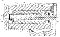
图1是按照本发明的技术装配起来的一螺杆压缩机的一部分的剖视图;Fig. 1 is a sectional view of a part of a screw compressor assembled according to the technique of the present invention;
图2是对应于图1的分解图;以及Figure 2 is an exploded view corresponding to Figure 1; and
图3是表示本发明的装配工序的流程图。Fig. 3 is a flow chart showing the assembly process of the present invention.
在图1和2中,标号“10”总地表示一半密封螺杆压缩机,它具有一电动机机壳12和一转子外壳14,它两共同作用而形成一电动机室16。一由定子21和转子22组成的电动机位于电动机室16内。转子22是用收缩配合或其它合适的办法固装于轴30上,该轴由跨置的轴承32和34所支撑而可以旋转。电动机机壳12的孔12-1中装有一组波状弹簧38和轴承32,这些波状弹簧38由凸肩12-2支撑住以对轴承32施加偏压力,从而将轴30推向转子外壳。轴孔34装在转子外壳14的孔14-1中并由凸肩14-2支撑。轴承32和34分别抵靠在轴30的凸肩30-1和30-2上。轴30穿过轴承34和孔14-3伸入一齿轮箱(未图示),在其中该轴与一传动齿轮相啮合(未图示)。In FIGS. 1 and 2, reference numeral "10" generally designates a half-hermetic screw compressor having a
请特别参见图2。可以注意到,轴承32和34分别包括内锥环和辊子32-1和34-1,以及外座圈32-2和34-2。相应地,内锥环和辊子32-1和34-1可以分别单独装配于对应的外座圈32-2和34-2,反之亦然。See Figure 2 in particular. It will be noted that
图3表示了一螺杆压缩机的电动机和有关结构的装配步骤。如方框100所示,电动机机壳12的孔12-3的直径是精密机械加工的,以便为其它构件提供一定位基准。孔12-1是与孔12-3同心加工的,以使轴承32能正确定位。如方框102所示,定子21的外圆柱面21-2的直径是经精密加工的,使它能精确地安置在孔12-3中。如方框104所示,将定子21放置于电动机机壳12内,使外圆柱面21-2位于孔12-3内并与之相配合。如方框106所示,将弹簧38和外座圈32-2放置于孔12-1内。如方框108所示,将轴30、转子22、内轴承32-1和34-1装配成一个子部件。如方框110所示,安装方框108的子部件,使转子22位于定子21的孔21-1中,以及将内轴承32-1装在外座圈32-2内。如方框112所示,转子外壳孔14-1和14-4是同心加工的。孔14-4的直径必须与孔12-3的基本相等,这是因为它两都收置和配合于定子21的表面21-2。在实践中,孔12-3与表面21-2是一种紧的过盈配合,而孔14-4与表面21-2是一种较松的滑配合。所以,孔14-4比孔12-3稍大出一个构成较松配合所需的量。如方框114所示,外座圈34-2放置在孔14-1内。电动机机壳12与转子外壳14装配在一起,使定子21处于外壳14内,并使表面21-2配合于孔14-4,而内轴承34-1处在外座圈34-2内,见方框116。Figure 3 shows the assembly steps of the motor and related structures of a screw compressor. As indicated at block 100, the diameter of the bore 12-3 of the
从以上说明可清楚知道:精密机械加工的定子21的表面21-2与精密机械加工的孔12-3、14-4的共同作用可以将电动机机壳12和转子外壳14相对于定子21和它们彼此之间精确定位。由于孔12-1和14-1是分别与孔12-3和14-4同心加工的,故使轴承32和34以及轴30能精确定位。From the above description, it is clear that the interaction of the precision machined surface 21-2 of the
尽管已图示和描述了本发明的一个最佳实例,熟悉本领域的技术人员还可作出其它的变化设计。例如,可以不对定子的外径进行加工,而是精确地冲制定子铁芯叠片并将其精确地叠装起来,使其具有一足够精确但非经机械加工的外径尺寸,因为最终的衡准是外径尺寸的精度。尽管对本发明是以一种两件式辊子轴承描述的,但还可采用两种不同形式的轴承,即单件式滚动轴承,例如球轴承和套筒(或轴颈)式轴承。在采用单件式球轴承的情况下,整个组件可以或者装在轴上或者装在机壳中,不过需改为从一端装到另一端。在采用套筒式轴承的情况下,也可以将一单个轴承插入件或者安装在轴上,装在机壳内(多半如此),或者改为从一端安装到另一端。在这种情况下,插入件在安装后可以机械加工或不加工。如不加工,决定合格与否的直径是该插入件将要压入的那个孔(或超过片的直径)的;如对插件加工的话,决定合格与否的直径变成轴承本身的加工表面。所以,应指出,本发明的范围只由所附权利要求的范围所限定。While a preferred embodiment of the invention has been illustrated and described, other variations can be devised by those skilled in the art. For example, instead of machining the outer diameter of the stator, the stator core laminations can be precisely punched and stacked precisely to have a sufficiently precise but non-machined outer diameter, because the final The criterion is the accuracy of the outer diameter. Although the invention has been described in terms of a two-piece roller bearing, two different types of bearings can be used, namely single-piece rolling bearings such as ball bearings and sleeve (or journal) bearings. In the case of one-piece ball bearings, the entire assembly can be mounted either on the shaft or in the housing, but instead from one end to the other. In the case of sleeve bearings, it is also possible to mount a single bearing insert either on the shaft, in the housing (in most cases), or alternatively from one end to the other. In this case, the insert may or may not be machined after installation. If it is not processed, the diameter that determines whether it is qualified or not is the hole that the insert will be pressed into (or exceeds the diameter of the sheet); if the insert is processed, the diameter that determines whether it is qualified or not becomes the machined surface of the bearing itself. Therefore, it should be noted that the scope of the present invention is limited only by the scope of the appended claims.
Claims (4)
Applications Claiming Priority (2)
| Application Number | Priority Date | Filing Date | Title |
|---|---|---|---|
| US08/753,629 US5758404A (en) | 1996-11-27 | 1996-11-27 | Method of assembling a motor |
| US08/753,629 | 1996-11-27 |
Publications (2)
| Publication Number | Publication Date |
|---|---|
| CN1185680A CN1185680A (en) | 1998-06-24 |
| CN1069456C true CN1069456C (en) | 2001-08-08 |
Family
ID=25031477
Family Applications (1)
| Application Number | Title | Priority Date | Filing Date |
|---|---|---|---|
| CN97123002A Expired - Fee Related CN1069456C (en) | 1996-11-27 | 1997-11-24 | Guiding package |
Country Status (8)
| Country | Link |
|---|---|
| US (2) | US5758404A (en) |
| EP (1) | EP0851558B1 (en) |
| JP (1) | JPH10174349A (en) |
| KR (1) | KR100302089B1 (en) |
| CN (1) | CN1069456C (en) |
| BR (1) | BR9705910B1 (en) |
| DE (1) | DE69734434T2 (en) |
| ES (1) | ES2247620T3 (en) |
Families Citing this family (19)
| Publication number | Priority date | Publication date | Assignee | Title |
|---|---|---|---|---|
| JPH0946983A (en) * | 1995-05-23 | 1997-02-14 | Fanuc Ltd | Finishing method for frame of electric motor and electric motor processed by this method |
| US5767596A (en) * | 1996-10-03 | 1998-06-16 | General Electric Company | Dynamoelectric machine and processes for making the same |
| US6122817A (en) * | 1997-09-19 | 2000-09-26 | Alliedsignal Inc. | Rotor assembly having lamination stack that is separately piloted and clamped |
| US6148501A (en) * | 1998-04-14 | 2000-11-21 | Seagate Technology Llc | Fabrication means for in-hub spindle with separate fluid dynamic bearings |
| US6484389B1 (en) * | 1999-12-20 | 2002-11-26 | Ford Global Technologies, Inc. | Apparatus for pilotless self-centering installation of a starter-alternator |
| US6204577B1 (en) * | 2000-01-05 | 2001-03-20 | Jeffrey Eliot Chottiner | Method and apparatus for space-saving installation of a starter-alternator |
| GB0229969D0 (en) * | 2002-12-21 | 2003-01-29 | Johnson Electric Sa | A motor and gearbox combination |
| US7091640B2 (en) * | 2004-05-26 | 2006-08-15 | Emerson Electric Co. | Motor with a multifunction bearing cap and method of assembly |
| US20060071564A1 (en) * | 2004-10-04 | 2006-04-06 | Stewart William P | Apparatus and methods of retaining a stator within a housing of an electric machine |
| US7931448B2 (en) * | 2006-08-01 | 2011-04-26 | Federal Mogul World Wide, Inc. | System and method for manufacturing a brushless DC motor fluid pump |
| US8488293B2 (en) * | 2009-12-21 | 2013-07-16 | Caterpillar Inc. | Electrical bearing ground device |
| CN102170198B (en) * | 2011-04-15 | 2014-10-22 | 无锡新大力电机有限公司 | Permanent magnet motor assembling tool |
| US9496775B2 (en) * | 2013-06-19 | 2016-11-15 | Tesla Motors, Inc. | Controlling end ring balance in pre-balancing spinning process |
| WO2016168423A1 (en) | 2015-04-14 | 2016-10-20 | Capital One Services, LLC. | Tamper-resistant dynamic transaction card and method of providing a tamper-resistant dynamic transaction card |
| CN108533492B (en) * | 2018-02-05 | 2020-02-07 | 珠海格力电器股份有限公司 | Compressor and air conditioner with same |
| US11791675B2 (en) * | 2020-03-06 | 2023-10-17 | Lc Advanced Motor Technology Corporation | Housing for a rotary electric machine and associated laminations |
| CN111953159B (en) * | 2020-08-14 | 2021-08-17 | 浙江震环数控机床股份有限公司 | Conical motor casing processing equipment and using method thereof |
| DE102020212589A1 (en) * | 2020-10-06 | 2022-04-07 | Zf Friedrichshafen Ag | Shaft grounding assembly, gearbox, and electric final drive |
| DE102021213387A1 (en) * | 2021-11-29 | 2023-06-01 | Zf Friedrichshafen Ag | Arrangement for grounding a shaft |
Citations (1)
| Publication number | Priority date | Publication date | Assignee | Title |
|---|---|---|---|---|
| JPS558253A (en) * | 1978-06-30 | 1980-01-21 | Matsushita Electric Works Ltd | Motor |
Family Cites Families (7)
| Publication number | Priority date | Publication date | Assignee | Title |
|---|---|---|---|---|
| US2819417A (en) * | 1954-11-18 | 1958-01-07 | John P Glass | Synchro construction and method for making same |
| US3268986A (en) * | 1963-05-07 | 1966-08-30 | Gen Electric | Method of manufacturing dynamo-electric machines |
| US3814961A (en) * | 1972-08-02 | 1974-06-04 | Ambac Ind | Trolling motor structure |
| US4118644A (en) * | 1974-10-12 | 1978-10-03 | Firma Schulte Elektrotechnik Kg | Electrical machinery |
| US4736869A (en) * | 1986-08-22 | 1988-04-12 | Expert Corporation | Submersible sealed housing |
| JPS63202251A (en) * | 1987-02-17 | 1988-08-22 | Fanuc Ltd | Insertion of rotor into motor and motor applied with said method |
| US5287030A (en) * | 1992-03-23 | 1994-02-15 | Electric Motors And Specialties, Inc. | Electric motor construction |
-
1996
- 1996-11-27 US US08/753,629 patent/US5758404A/en not_active Expired - Lifetime
-
1997
- 1997-10-24 US US08/957,727 patent/US5869914A/en not_active Expired - Lifetime
- 1997-11-14 ES ES97630078T patent/ES2247620T3/en not_active Expired - Lifetime
- 1997-11-14 EP EP97630078A patent/EP0851558B1/en not_active Expired - Lifetime
- 1997-11-14 DE DE69734434T patent/DE69734434T2/en not_active Expired - Lifetime
- 1997-11-24 CN CN97123002A patent/CN1069456C/en not_active Expired - Fee Related
- 1997-11-26 BR BRPI9705910-2A patent/BR9705910B1/en not_active IP Right Cessation
- 1997-11-26 KR KR1019970062993A patent/KR100302089B1/en not_active Expired - Fee Related
- 1997-11-27 JP JP9325844A patent/JPH10174349A/en active Pending
Patent Citations (1)
| Publication number | Priority date | Publication date | Assignee | Title |
|---|---|---|---|---|
| JPS558253A (en) * | 1978-06-30 | 1980-01-21 | Matsushita Electric Works Ltd | Motor |
Also Published As
| Publication number | Publication date |
|---|---|
| DE69734434T2 (en) | 2006-07-06 |
| BR9705910A (en) | 1999-03-02 |
| KR100302089B1 (en) | 2002-01-17 |
| EP0851558A3 (en) | 1999-09-29 |
| US5869914A (en) | 1999-02-09 |
| EP0851558B1 (en) | 2005-10-26 |
| US5758404A (en) | 1998-06-02 |
| EP0851558A2 (en) | 1998-07-01 |
| KR19980042769A (en) | 1998-08-17 |
| ES2247620T3 (en) | 2006-03-01 |
| CN1185680A (en) | 1998-06-24 |
| BR9705910B1 (en) | 2010-06-29 |
| JPH10174349A (en) | 1998-06-26 |
| DE69734434D1 (en) | 2005-12-01 |
Similar Documents
| Publication | Publication Date | Title |
|---|---|---|
| CN1069456C (en) | Guiding package | |
| US6342739B1 (en) | Small-sized motor and method of manufacturing the same | |
| US6741001B2 (en) | Spindle motor and bearing assembly | |
| EP0592214A2 (en) | Compound ball-bearing | |
| US20020185927A1 (en) | Motor | |
| US7442016B2 (en) | Scroll pump and method of assembling same | |
| CN109538638B (en) | High-speed rotor and assembly method thereof | |
| EP0758155B1 (en) | Electric drive motor with a compound bearing assembly | |
| KR100483234B1 (en) | Fuel pump | |
| EP0752539B1 (en) | Bearing assembly and method of manufacturing the same | |
| EP1717930A2 (en) | Electric actuator and a motor used therein | |
| JP2596301Y2 (en) | Fluid compressor | |
| US20230291267A1 (en) | Motor dust cover design and interface with coupling | |
| JP2002017063A (en) | Motor and method of manufacturing the same | |
| EP0860931A2 (en) | A rotary machine of inner rotor type | |
| US7752733B1 (en) | Laser welded step motor construction with compact end cap and stator lamination positioning | |
| US5969452A (en) | Magnetic bearing construction | |
| EP1961585A1 (en) | Bearing apparatus for axle and method of manufacturing the same | |
| JPH0239638B2 (en) | ||
| JP2022156317A (en) | Electrically driven pump | |
| CN219436763U (en) | Brushless motor interference assembly structure | |
| JP2838247B2 (en) | Manufacturing method of stepping motor | |
| JP2003111342A (en) | Bearing structure having self-aligning function for brushless dc fan motor | |
| JP3201862B2 (en) | Spindle motor | |
| CN118357675A (en) | Assembling method of speed reducer assembly |
Legal Events
| Date | Code | Title | Description |
|---|---|---|---|
| C10 | Entry into substantive examination | ||
| SE01 | Entry into force of request for substantive examination | ||
| C06 | Publication | ||
| PB01 | Publication | ||
| C14 | Grant of patent or utility model | ||
| GR01 | Patent grant | ||
| CF01 | Termination of patent right due to non-payment of annual fee | ||
| CF01 | Termination of patent right due to non-payment of annual fee |
Granted publication date: 20010808 Termination date: 20151124 |