Disclosure of Invention
The technical problem solved by the invention is as follows: the unmanned electric university student formula racing car and the control method thereof overcome the defects of the prior art, realize the unmanned control and driving of the car on mechanical hardware, and improve the positioning precision of the car
The technical scheme of the invention is as follows: unmanned electronic college student formula cycle car, its characterized in that includes: the device comprises a front axle, a rear axle, a frame, a driving wheel, a steering wheel, double motors, a motor reducer, a half axle, a motor controller, a power battery pack, a battery management system, a steering engine, a steering engine reducer, a corner sensor, a braking steering engine reducer, a wheel speed sensor, a camera, an industrial personal computer, an ECU (electronic control Unit) of the whole vehicle controller, a GPS moving end, a GPS antenna, a laser radar and a radio station moving end;
the frame includes: a main ring, a front ring;
a power battery pack, comprising: high voltage battery, DC/DC, low voltage battery, inverter;
the unmanned electric college formula car is also externally provided with a radio station terminal and a GPS reference station;
the double motors are arranged in the middle of the rear axle, and the motor speed reducer is arranged on the outer sides of the double motors; the half shaft is connected with the motor reducer and the driving wheel, and the motor controller is arranged below the rear part of the main ring and in front of the double motors;
the power battery pack and the battery management system are arranged on the frame; the steering engine is connected with a steering engine reducer, the corner sensor is arranged on the steering engine reducer, and the steering engine, the steering engine reducer and the corner sensor are all arranged above a steering rack of a vehicle;
the brake steering engine and the brake steering engine speed reducer are both arranged on the frame, the brake steering engine is connected with the brake steering engine speed reducer, and the brake steering engine speed reducer is connected with the brake main cylinder;
the wheel speed sensors are respectively arranged in the driving wheel and the steering wheel; the camera is arranged in the middle of the top of the vehicle head and faces the front of the vehicle head; the radio station mobile terminal, the industrial personal computer, the whole vehicle controller ECU and the GPS mobile terminal are all arranged on the frame; GPS antennas are arranged at the front part and the rear part of the vehicle; the connecting line between the GPS antennae at the front part and the rear part of the vehicle is parallel to the central axis of the vehicle; the laser radar is arranged on the roof and is positioned at the front end of the main ring;
the high-voltage battery is connected with the motor controller, the high-voltage battery outputs two-phase direct current to the motor controller, and the motor controller converts the two-phase direct current into three-phase alternating current to provide electric energy for the double motors; meanwhile, the high-voltage battery supplies power to the low-voltage battery through DC/DC; the low-voltage battery is connected with the inverter and supplies power to the industrial personal computer through the inverter; meanwhile, the low-voltage battery supplies power to the camera, the laser radar, the GPS moving end, the radio station moving end, the brake steering engine, the steering engine and the cancom signal converter;
the torque output by the steering engine is output to a steering rack through a steering engine speed reducer so as to control the steering of a steering wheel;
the torque generated by the double motors is transmitted to the half shaft after being reduced and increased in torque through the motor reducer, and is output to the driving wheel through the half shaft, so that the vehicle generates power;
the torque output by the brake steering engine is output to a brake main cylinder through a brake steering engine speed reducer, so that the brake caliper holds the brake pad through a brake hydraulic pipeline to brake the vehicle;
the camera can transmit the acquired image in front of the vehicle to the industrial personal computer, meanwhile, the laser radar transmits the acquired distance information of the obstacle in front of the vehicle to the industrial personal computer, and the GPS antenna receives satellite signals and transmits the satellite signals to the GPS mobile terminal; the GPS reference station sends the position of the GPS reference station to a radio station mobile terminal loaded on a vehicle in real time through a radio station terminal, and the radio station mobile terminal transmits the position of the GPS reference station to the GPS mobile terminal;
the GPS mobile terminal obtains the GPS coordinates of the vehicle according to the satellite signals, corrects the GPS coordinates of the vehicle according to the position of the GPS reference station and the satellite signals, and sends the corrected GPS coordinates to the industrial personal computer; the industrial personal computer determines the target direction and the target speed of the vehicle according to the image in front of the vehicle collected by the camera, the distance information of the obstacle in front of the vehicle collected by the laser radar and the GPS coordinate of the vehicle, and transmits the target direction and the target speed to the ECU of the whole vehicle controller; the ECU of the whole vehicle controller simultaneously receives a steering wheel steering angle signal acquired by a steering angle sensor in real time and a wheel rotating speed signal acquired by a wheel speed sensor; determining the real-time direction and speed of the vehicle according to the collected steering wheel rotation angle signal and the collected wheel rotation speed signal; the ECU of the vehicle controller compares the target direction and the target speed of the vehicle with the real-time direction and the real-time speed of the vehicle respectively, and sends instructions to the braking steering engine and the steering engine, so that the real-time direction and the real-time speed of the vehicle are close to the target direction and the target speed of the vehicle, the target direction and the target speed of the vehicle are finally reached, and the direction and the speed of the vehicle are controlled.
The frame is provided with a cancom signal converter; the vehicle control unit ECU sends commands to the brake steering engine and the steering engine, and the can signal is converted into a 485 signal through the can signal converter.
The GPS antennae are respectively installed in the front and the rear of the racing car, GPS reference stations are arranged around a track on which the racing car runs, the accurate positions of the GPS reference stations are known, the correction numbers from the GPS reference stations to satellites, namely correction parameters, can be obtained according to the accurate positions of the GPS reference stations, the GPS reference stations can send the correction parameters to the racing car in real time through radio stations, the racing car can simultaneously receive satellite signals and GPS reference station signals, and high-precision positioning can be obtained by utilizing a difference principle.
The control method of the unmanned electric university student formula racing car comprises the following steps:
(1) determining road environment information according to the laser radar and the camera;
(2) and determining and calculating the vehicle travelable route according to the road environment information, thereby realizing the autonomous driving of the vehicle.
The control method of the unmanned electric university student formula racing car comprises the following steps:
(1) identifying the pedestrian in front of the vehicle according to the camera, and determining the position information of the pedestrian to be tracked in front of the vehicle in real time;
(2) and determining the traveling direction and the traveling speed of the vehicle according to the real-time pedestrian position information.
Compared with the prior art, the invention has the advantages that:
(1) the invention replaces the braking and steering mechanism of the traditional vehicle by the scheme of the braking steering engine and the related mechanical transmission mechanism as well as the steering engine and the related mechanical transmission mechanism, thereby realizing the unmanned control and driving of the vehicle on mechanical hardware.
(2) According to the invention, through the scheme of combining the camera module and the laser radar module, the accuracy and stability of road condition environment identification are improved, the stability of the vehicle in an unmanned driving mode is improved, and the accuracy of vehicle obstacle avoidance is improved.
(3) The invention greatly improves the positioning precision of the vehicle by the scheme of combining and matching the GPS mobile terminal on the vehicle with the ground GPS terminal and utilizing the differential principle.
(4) The invention realizes the tracking driving mode of the vehicle to the pedestrian through the technical scheme of the camera on the vehicle and the pedestrian recognition.
(5) The invention enables the university student formula car to realize unmanned operation, enables the formula car to sense the road and plan the vehicle running line, and realizes four-level automatic unmanned driving.
Detailed Description
The basic idea of the invention is as follows: the unmanned electric university student formula racing car and the control method thereof are provided, wherein mechanisms such as a steering wheel, a steering column, an accelerator pedal, a brake pedal and the like of a traditional vehicle are removed, a steering engine and a speed reducer thereof are arranged at a steering mechanism of the vehicle, and the steering engine and the speed reducer thereof are braked on the vehicle to replace an original manual control mechanism so as to realize an unmanned operation system; for a vehicle sensing element, a corner sensor, a wheel speed sensor, a camera, a laser radar and GPS related equipment are additionally arranged. The sensing element is used for identifying road environment information, determining a road and avoiding obstacles, so that a vehicle runnable route is calculated, the vehicle can autonomously run in the road, and local path planning is realized. In addition, the appointed route can be manually input, so that the vehicle can run along the appointed route, and the global route planning is realized. And meanwhile, the vehicle can also follow the pedestrian, and the vehicle can drive behind the pedestrian. When a person suddenly stops, the vehicle can also be automatically braked and stopped, which is called as an individual soldier tracking technology for short. Finally, the university student formula car is unmanned, the formula car senses the road to plan the vehicle running line, and four-level automatic unmanned driving is achieved.
The invention is described in further detail below with reference to the figures and specific embodiments.
Unmanned electronic college student formula cycle car, its characterized in that includes: the device comprises a front axle, a rear axle, a frame, a driving wheel, a steering wheel, double motors 17, a motor reducer 16, a half axle, a motor controller 14, a power battery pack 3, a battery management system 2, a steering engine 10, a steering engine reducer 28, a corner sensor 9, a braking steering engine 7, a braking steering engine reducer 8, a wheel speed sensor 1, a camera 5, an industrial personal computer 12, a whole vehicle controller ECU13, a GPS moving end 11, a GPS antenna 6, a laser radar 15 and a radio station moving end 4;
a vehicle frame, comprising: a main ring 18, a front ring 19;
a power battery pack 3 comprising: high-voltage battery 25, DC/DC26, low-voltage battery 27, inverter 21;
the unmanned electric university student formula car is also externally provided with a radio station terminal 23 and a GPS reference station 24;
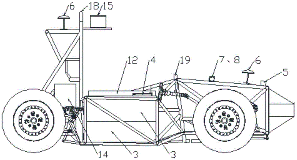
the component arrangement of the whole vehicle can be seen in a component arrangement diagram of the whole vehicle in figure 1 and a side view of the whole vehicle in figure 2. The direction of the tail of the vehicle pointing to the head of the vehicle is defined as the front, and the direction of the head of the vehicle pointing to the tail of the vehicle is defined as the rear. As shown in the figure: the double motors 17 of the whole vehicle element layout drawing are arranged in the middle of the rear axle, and the motor reducers 16 are arranged on the outer sides of the double motors 17; the half shaft is connected with a motor reducer 16 and a driving wheel, and a motor controller 14 is arranged at the rear lower part of the main ring 18 and is positioned in front of the double motors 17; the power battery packs 3 and the battery management system 2 are arranged on the frame, and the number of the power battery packs 3 is 4, and the power battery packs are positioned on two sides of the cockpit, two on each side; the steering engine 10 is connected with a steering engine reducer 28, the corner sensor 9 is mounted on the steering engine reducer 28, the steering engine 10, the steering engine reducer 28 and the corner sensor 9 are mounted above a steering rack of a vehicle, the steering rack is positioned on a frame between two steering wheels and meets the Ackermann steering geometry of the vehicle; the brake steering engine 7 and the brake steering engine speed reducer 8 are both mounted on the top of the vehicle head frame, the brake steering engine 7 is connected with the brake steering engine speed reducer 8, and the brake steering engine speed reducer 8 is connected with the brake main cylinder; 4 wheel speed sensors 1 are respectively arranged in 2 driving wheels and 2 steering wheels; the camera 5 is arranged in the middle of the top of the vehicle head and faces the front of the vehicle head; the radio station mobile terminal 4, the industrial personal computer 12, the vehicle control unit ECU13 and the GPS mobile terminal 11 are all arranged on the frame; 2 GPS antennas 6 are arranged at the front part and the rear part of the vehicle; the connecting line between the GPS antennas 6 at the front part and the rear part of the vehicle and the central axis of the vehicle parallel to the central axis of the vehicle are the connecting line between the center of the head of the vehicle and the center of the tail of the vehicle; the laser radar 15 is arranged on the roof and is positioned at the front end of the main ring;
see figure 3 for circuit signal connections of the present invention. The high-voltage battery 25 is connected with the motor controller 14, the high-voltage battery 25 outputs two-phase direct current to the motor controller 14, and the motor controller 14 converts the two-phase direct current into three-phase alternating current to provide electric energy for the double motors 17; meanwhile, the high-voltage battery 25 supplies power to the low-voltage battery 27 through the DC/DC 26; the low-voltage battery 27 is connected with the inverter 21, and the low-voltage battery 27 supplies power to the industrial personal computer 12 through the inverter 21; meanwhile, the low-voltage battery 27 supplies power to the camera 5, the laser radar 15, the GPS mobile terminal 11, the radio station mobile terminal 4, the brake steering engine 7, the steering engine 10 and the cancom signal converter 22;
for an unmanned control system of a vehicle, torque output by a vehicle steering engine 10 is output to a steering rack through a steering engine reducer 28, so that steering of a steering wheel is controlled; the torque output by the brake steering engine 7 is output to a brake master cylinder through a brake steering engine speed reducer 8, the brake master cylinder works to enable the oil pressure in a brake hydraulic pipeline to be increased, and therefore the brake calipers work to enable the brake calipers to hold brake pads through the brake hydraulic pipeline, and a vehicle is braked; the torque generated by the two motors 17 is transmitted to the half shaft after being reduced and increased in torque through the two motor reducers 16 on the two sides of the motors, and is output to the driving wheel through the half shaft, so that the vehicle generates power;
the torque generated by the double motors 17 is transmitted to the half shaft after being decelerated and torque-increased by the motor reducer 16, and is output to the driving wheel by the half shaft, so that the vehicle generates power;
the torque output by the brake steering engine 7 is output to a brake main cylinder through a brake steering engine speed reducer 8, so that brake calipers clamp brake pads through a brake hydraulic pipeline to brake a vehicle;
the camera 5 can transmit the acquired image in front of the vehicle to the industrial personal computer 12, and the whole picture is used as a variable to be input. The industrial personal computer 12 analyzes and calculates the pictures. Aiming at the road condition of the track, as the track is laid out by pile barrels, the industrial personal computer 12 extracts the positions of the pile barrels in the picture, the pile barrels on one side of the road are taken as a reference, the pile barrels on the side are respectively matched with the pile barrels on the other side of the road corresponding to the pile barrels, upper vertex pixel points of each pair of pile barrels are extracted firstly, then midpoint pixel points of a connecting line of the upper vertex pixel points of each pair of pile barrels are calculated and extracted, a smooth curve passing through the midpoint is calculated according to the extracted midpoint pixel points, and the curve is just the target path of the vehicle. For a general road, the industrial personal computer 12 determines a road range in the front position environment by extracting yellow and white lane lines in the picture, identifies obstacles in the determined road range, eliminates the area where the obstacles are located, and takes the rest as a drivable area. And after the travelable area is determined, measuring and calculating the width of the travelable area and comparing the measured width with the width of the vehicle body, if the road is divided into a plurality of sections by the barrier, selecting the widest travelable area to be compared with the vehicle body, and if the travelable area is wider than the vehicle body, selecting the center line of the travelable area as a target travelling route according to the travelable area determined by the vehicle. And if the drivable area is smaller than the width of the vehicle body, stopping the driving of the vehicle. And the target route point is represented by a GPS point to facilitate the tracking of the vehicle. The identification of the pile barrel and the obstacle is realized by uploading tens of thousands of photos of the pile barrel and tens of thousands of photos of the pedestrian and other obstacles and learning by using a CNN convolutional neural network. The network has eight layers, from L1 to 18. The first layer is a convolutional layer and all other layers are fully connected. The input to the network has two 9 x 9 gray scale image patches. The first convolutional layer has 32 kernel sizes 5 × 5 × 1. The L2 and L3 layers all have 200 neurons. Then from L5 to L8, there were 300 nerves per layer. L8 has the ability to generate an architectural description that is distributed over two classes (good match and bad match) and section C by two real numbers input by the softmax function as shown in fig. 4.
Meanwhile, the laser radar 15 transmits the acquired distance information of the obstacle in front of the vehicle to the industrial personal computer 12, and the laser radar transmits 16 laser pulse beams parallel to the horizontal line within a 30-degree included angle to scan the road condition environment 180 degrees in front when acquiring the distance information. The light receiver receives the reflected laser pulses and converts the laser pulses into electrical signals which are transmitted to the industrial personal computer 12 for information processing and calculation. Thereby obtaining a three-dimensional point cloud picture of the environment in front of the vehicle. And then analyzing and extracting the point cloud pictures. The blank in the cloud point map is the accessible barrier-free road for vehicles.
Laser radar 15 and camera 5 simultaneous working to camera 5 is main laser radar 15 and is assisted to improve road perception's exactness and reliability.
The information of the identified center line coordinate of the road is transmitted to the vehicle worker 12 control machine, and the coordinate of the driving route can be a GPS coordinate. Data is transmitted to the ECU13 through the calculation of the industrial personal computer 12, and the ECU13 transmits the data to the motor controller 14 in a can signal, so that the vehicle runs along the identified route. And the full-automatic running is realized.
In addition, the coordinates of the driving route can be input into the racing car in advance by inputting the GPS coordinates, so that the car can drive according to the route. This relies primarily on high precision positioning. The global route planning depends on a GPS system, GPS antennae 6 are respectively arranged in the front and the rear of the vehicle, and the GPS antennae 6 receive satellite signals and send the satellite signals to a GPS mobile terminal 11. A GPS reference station 24 is arranged around the track, the precise position of which is known, and then the correction number from the reference station to the satellite is obtained, the reference station 24 transmits the data to the mobile station terminal 4 mounted on the vehicle in real time through the radio station 23, and the mobile station terminal 4 transmits the position of the GPS reference station to the mobile GPS terminal 11. The vehicle can simultaneously receive satellite signals and base station signals, and the satellite signals and the base station signals are processed to obtain very high-precision positioning by utilizing a difference principle. Meanwhile, the connecting line of the front antenna and the rear antenna can also determine the direction of the vehicle body.
The GPS antenna 6 receives satellite signals and sends the satellite signals to the GPS mobile terminal 11; the GPS reference station 24 sends the position of the GPS reference station to the radio station mobile terminal 4 loaded on the vehicle in real time through the radio station terminal 23, and the radio station mobile terminal 4 transmits the position of the GPS reference station to the GPS mobile terminal 11;
the GPS mobile terminal 11 obtains the GPS coordinates of the vehicle according to the satellite signals, corrects the GPS coordinates of the vehicle according to the position of the GPS reference station and obtains the GPS coordinates of the vehicle according to the satellite signals, and sends the corrected GPS coordinates to the industrial personal computer 12;
the whole vehicle control module is divided into a longitudinal controller and a transverse controller.
The vehicle is used for judging the position to obtain a target speed of the position through real-time position measurement, meanwhile, the current speed of the vehicle is measured through the wheel speed sensor 1 and compared with the target speed, when the current speed of the vehicle is smaller than the target speed of the vehicle, the vehicle controller 13 transmits a signal to the motor controller 14 so as to increase the current speed of the motor 17, and when the current speed of the vehicle is larger than the target speed of the vehicle, the vehicle controller 13 transmits a signal to the brake steering engine 7 so as to reduce the speed of the vehicle. Because the signal transmission of the radio station, the brake steering engine and the steering engine is 485 signals, and the signal receiving and sending of the vehicle controller 13 are can signals, the cancom is used for signal conversion in the middle, the 485 signals are converted into can signals which are transmitted to the vehicle controller 13 by the radio station 4, and residual signals are converted into 485 signals which are transmitted to the brake steering engine or the steering engine by the vehicle controller 13.
The lateral controller is the trajectory control. The vehicle calculates the direction deflection angle of the steering wheel of the vehicle by measuring the vehicle speed and the curvature radius at the position of the vehicle in real time so as to ensure that the direction of the vehicle is consistent with the direction of the path, but the vehicle cannot be ensured to run along the running route only by the deflection angle. Meanwhile, the vehicle calculates the deviation distance between the vehicle mass center and the target running path by measuring and calculating the actual position GPS point of the vehicle in real time, and calculates the vehicle distance deflection angle through the deviation distance, so that the vehicle is ensured to run along the target path.
The optimal method for realizing individual soldier tracking comprises the steps of shooting the road condition in front of the vehicle in real time through the binocular camera 5 installed in the front of the vehicle, transmitting data to the industrial personal computer 12, then identifying and extracting pedestrians in front of the vehicle according to the pedestrian contours, obtaining pedestrian contour identification through learning in advance, uploading ten thousand pedestrian pictures by utilizing a cnn convolutional neural network, and identifying the pedestrians. As shown in fig. 5, the finally outputted environmental person identification image is obtained, and the identified person is identified by a green frame in the picture. In each real-time picture shot, the industrial personal computer selects the central pixel point of the area where the pedestrian is located through the pedestrian who draws, and compares with the picture central line, calculates error X, thereby the steering wheel angle is calculated through enlarging error X according to certain proportionality coefficient K this moment, and the industrial personal computer sends the steering command to vehicle control unit 13, and vehicle control unit 13 sends the command to steering engine 10 again and controls the steering wheel to rotate according to the calculated angle, makes error X reduce. At the next moment, the industrial personal computer continuously analyzes and calculates the error X and the direction turning angle, and continuously sends the real-time turning wheel turning angle to the vehicle control unit 13, so that the error X is continuously reduced, and the direction tracking is realized. The distance control is to measure and calculate the real-time distance between the vehicle head and the pedestrian according to the binocular camera, the distance is continuously compared with a preset value, and the industrial personal computer 12 continuously sends an acceleration and deceleration command to the vehicle control unit 14 through a PID algorithm to ensure that the real-time distance floats up and down at the preset distance. When the real-time distance is larger than the preset distance, the industrial personal computer 12 sends a command to the motor 17 controller to control the motor 17 to increase torque output, so that the speed of the vehicle is increased, and the distance between the current vehicle and the pedestrian is reduced. When the distance between the vehicle and the pedestrian is smaller than the preset distance, the industrial personal computer 12 sends a deceleration command to the vehicle control unit 14, the vehicle control unit 14 controls the brake steering engine 7, and the vehicle is braked to decelerate so that the current distance is increased. If more pedestrians exist in front of the vehicle, the vehicle selects the pedestrian closest to the vehicle to track.