CN106955840B - Vibrating screen for drilling fluid mud - Google Patents
Vibrating screen for drilling fluid mud Download PDFInfo
- Publication number
- CN106955840B CN106955840B CN201710318443.9A CN201710318443A CN106955840B CN 106955840 B CN106955840 B CN 106955840B CN 201710318443 A CN201710318443 A CN 201710318443A CN 106955840 B CN106955840 B CN 106955840B
- Authority
- CN
- China
- Prior art keywords
- screen
- drilling fluid
- air knife
- fluid mud
- box
- Prior art date
- Legal status (The legal status is an assumption and is not a legal conclusion. Google has not performed a legal analysis and makes no representation as to the accuracy of the status listed.)
- Active
Links
- 238000005553 drilling Methods 0.000 title claims abstract description 67
- 239000012530 fluid Substances 0.000 title claims abstract description 53
- 239000007788 liquid Substances 0.000 claims abstract description 24
- 239000000126 substance Substances 0.000 claims abstract description 11
- 238000001035 drying Methods 0.000 claims abstract description 5
- 239000003638 chemical reducing agent Substances 0.000 claims abstract description 4
- 238000009434 installation Methods 0.000 claims description 28
- 230000005540 biological transmission Effects 0.000 claims description 16
- 238000000034 method Methods 0.000 claims description 16
- 238000007789 sealing Methods 0.000 claims description 14
- 239000007789 gas Substances 0.000 claims description 11
- XLYOFNOQVPJJNP-UHFFFAOYSA-N water Substances O XLYOFNOQVPJJNP-UHFFFAOYSA-N 0.000 claims description 8
- 239000002002 slurry Substances 0.000 claims description 5
- 238000002485 combustion reaction Methods 0.000 claims description 2
- 239000007791 liquid phase Substances 0.000 claims description 2
- 230000035699 permeability Effects 0.000 claims description 2
- 239000007790 solid phase Substances 0.000 claims description 2
- 238000007664 blowing Methods 0.000 claims 1
- 239000010419 fine particle Substances 0.000 claims 1
- 238000005086 pumping Methods 0.000 claims 1
- 238000005520 cutting process Methods 0.000 abstract description 16
- 239000004744 fabric Substances 0.000 abstract description 10
- 239000000463 material Substances 0.000 abstract description 5
- 238000000926 separation method Methods 0.000 abstract description 4
- 238000003860 storage Methods 0.000 abstract description 4
- 230000000694 effects Effects 0.000 abstract description 3
- 239000003208 petroleum Substances 0.000 abstract description 3
- 238000012216 screening Methods 0.000 description 12
- 238000010586 diagram Methods 0.000 description 8
- 238000010276 construction Methods 0.000 description 4
- 239000012065 filter cake Substances 0.000 description 4
- YXFVVABEGXRONW-UHFFFAOYSA-N Toluene Chemical compound CC1=CC=CC=C1 YXFVVABEGXRONW-UHFFFAOYSA-N 0.000 description 3
- YNQLUTRBYVCPMQ-UHFFFAOYSA-N Ethylbenzene Chemical compound CCC1=CC=CC=C1 YNQLUTRBYVCPMQ-UHFFFAOYSA-N 0.000 description 2
- 238000004140 cleaning Methods 0.000 description 2
- 238000009826 distribution Methods 0.000 description 2
- 230000007613 environmental effect Effects 0.000 description 2
- 239000010802 sludge Substances 0.000 description 2
- CTQNGGLPUBDAKN-UHFFFAOYSA-N O-Xylene Chemical compound CC1=CC=CC=C1C CTQNGGLPUBDAKN-UHFFFAOYSA-N 0.000 description 1
- 238000009825 accumulation Methods 0.000 description 1
- 230000009286 beneficial effect Effects 0.000 description 1
- 150000001555 benzenes Chemical class 0.000 description 1
- 230000015572 biosynthetic process Effects 0.000 description 1
- 150000002430 hydrocarbons Chemical class 0.000 description 1
- 239000003209 petroleum derivative Substances 0.000 description 1
- 239000008096 xylene Substances 0.000 description 1
Images





Classifications
-
- B—PERFORMING OPERATIONS; TRANSPORTING
- B07—SEPARATING SOLIDS FROM SOLIDS; SORTING
- B07B—SEPARATING SOLIDS FROM SOLIDS BY SIEVING, SCREENING, SIFTING OR BY USING GAS CURRENTS; SEPARATING BY OTHER DRY METHODS APPLICABLE TO BULK MATERIAL, e.g. LOOSE ARTICLES FIT TO BE HANDLED LIKE BULK MATERIAL
- B07B1/00—Sieving, screening, sifting, or sorting solid materials using networks, gratings, grids, or the like
- B07B1/28—Moving screens not otherwise provided for, e.g. swinging, reciprocating, rocking, tilting or wobbling screens
-
- B—PERFORMING OPERATIONS; TRANSPORTING
- B07—SEPARATING SOLIDS FROM SOLIDS; SORTING
- B07B—SEPARATING SOLIDS FROM SOLIDS BY SIEVING, SCREENING, SIFTING OR BY USING GAS CURRENTS; SEPARATING BY OTHER DRY METHODS APPLICABLE TO BULK MATERIAL, e.g. LOOSE ARTICLES FIT TO BE HANDLED LIKE BULK MATERIAL
- B07B1/00—Sieving, screening, sifting, or sorting solid materials using networks, gratings, grids, or the like
- B07B1/42—Drive mechanisms, regulating or controlling devices, or balancing devices, specially adapted for screens
-
- B—PERFORMING OPERATIONS; TRANSPORTING
- B07—SEPARATING SOLIDS FROM SOLIDS; SORTING
- B07B—SEPARATING SOLIDS FROM SOLIDS BY SIEVING, SCREENING, SIFTING OR BY USING GAS CURRENTS; SEPARATING BY OTHER DRY METHODS APPLICABLE TO BULK MATERIAL, e.g. LOOSE ARTICLES FIT TO BE HANDLED LIKE BULK MATERIAL
- B07B1/00—Sieving, screening, sifting, or sorting solid materials using networks, gratings, grids, or the like
- B07B1/46—Constructional details of screens in general; Cleaning or heating of screens
-
- B—PERFORMING OPERATIONS; TRANSPORTING
- B07—SEPARATING SOLIDS FROM SOLIDS; SORTING
- B07B—SEPARATING SOLIDS FROM SOLIDS BY SIEVING, SCREENING, SIFTING OR BY USING GAS CURRENTS; SEPARATING BY OTHER DRY METHODS APPLICABLE TO BULK MATERIAL, e.g. LOOSE ARTICLES FIT TO BE HANDLED LIKE BULK MATERIAL
- B07B1/00—Sieving, screening, sifting, or sorting solid materials using networks, gratings, grids, or the like
- B07B1/46—Constructional details of screens in general; Cleaning or heating of screens
- B07B1/4609—Constructional details of screens in general; Cleaning or heating of screens constructional details of screening surfaces or meshes
-
- E—FIXED CONSTRUCTIONS
- E21—EARTH OR ROCK DRILLING; MINING
- E21B—EARTH OR ROCK DRILLING; OBTAINING OIL, GAS, WATER, SOLUBLE OR MELTABLE MATERIALS OR A SLURRY OF MINERALS FROM WELLS
- E21B21/00—Methods or apparatus for flushing boreholes, e.g. by use of exhaust air from motor
- E21B21/06—Arrangements for treating drilling fluids outside the borehole
- E21B21/063—Arrangements for treating drilling fluids outside the borehole by separating components
- E21B21/065—Separating solids from drilling fluids
- E21B21/066—Separating solids from drilling fluids with further treatment of the solids, e.g. for disposal
Landscapes
- Engineering & Computer Science (AREA)
- Life Sciences & Earth Sciences (AREA)
- Geology (AREA)
- Mining & Mineral Resources (AREA)
- Mechanical Engineering (AREA)
- Physics & Mathematics (AREA)
- Environmental & Geological Engineering (AREA)
- Fluid Mechanics (AREA)
- General Life Sciences & Earth Sciences (AREA)
- Geochemistry & Mineralogy (AREA)
- Treatment Of Sludge (AREA)
Abstract
The invention relates to a vibrating screen for drilling fluid mud, and belongs to the field of equipment for solid-liquid separation and drill chip drying treatment of petroleum drilling fluid. The vibrating screen comprises a frame, a driving roller, a driven roller, a driving motor, a screen and a vacuum box; one end of the rack is provided with a driving roller, a driving motor is arranged on the rack on one side of the driving roller, and the driving motor is connected with the driving roller through a speed reducer; the other end of the frame is provided with a driven roller through a tensioner, and the driving roller and the driven roller are provided with screens. The vibrating screen can effectively reduce the liquid content of the drill cuttings after separation, effectively remove harmful gas and organic volatile substances in the drill cuttings, and facilitate the collection, storage and transportation of the drill cuttings. And through the regulation to the angle of giving vent to anger of air sword and tolerance, can carry out the blowback to different places on the screen cloth, different kinds of material from this improvement mummification effect of mud, have positive meaning to the harm that reduces drill chip to atmospheric pollution and operation environment.
Description
Technical Field
The invention relates to a vibrating screen for drilling fluid mud, and belongs to the field of solid-liquid separation and drill chip drying treatment equipment for petroleum drilling fluid.
Background
In the process of petroleum drilling operation, drilling fluid is injected into a shaft through a drilling pipe column water hole and returns to a ground circulating system through an annular space formed between the drilling pipe column and the shaft. Drilling fluid carries drill cuttings out of the process of returning the drilling fluid out of the shaft, the drill cuttings are separated out through a vibrating screen, a desander and a centrifuge, and the separated drill cuttings contain a large amount of drilling fluid, formation gas and other pollution components.
At present, the separated drill cuttings are generally concentrated in wellsite lagoons, either solidified or landfilled. With the stricter and stricter environmental protection requirements and the enhancement of environmental protection awareness of enterprises, the requirement of zero emission or no landing of drill cuttings is provided. The drill cuttings are collected and transported to centralized treatment plants in a closed manner at home and abroad, and the drill cuttings are subjected to harmless treatment, and meanwhile, a new concept of the harmless treatment of the drill cuttings on a drilling site is provided in recent years. However, the treatment cost is generally high, and the popularization is difficult.
On the other hand, the drill cuttings separated by a vibrating screen or other equipment contain a large amount of liquid (generally, the liquid content is 60-70%), harmful gas and organic volatile substances. Not only the storage and transportation volume is large, but also the pollution caused by the liquid falling and the volatilization of gas and volatile substances is easy to occur in the storage and transportation process, and the total treatment amount of centralized treatment is increased, so that the cost of harmless treatment is overhigh.
Disclosure of Invention
The invention aims to: the vibrating screen for the drilling fluid mud can effectively reduce the liquid content of the separated drill cuttings and effectively remove harmful gas and organic volatile substances in the drill cuttings.
The technical scheme of the invention is as follows:
a vibrating screen for drilling fluid mud comprises a frame, a driving roller, a driven roller, a driving motor, a screen and a vacuum box; the method is characterized in that: one end of the rack is provided with a driving roller, the rack on one side of the driving roller is provided with a driving motor, and the driving motor is connected with the driving roller through a speed reducer; the other end of the rack is provided with a driven roller through a tensioner, the driving roller and the driven roller are provided with screens, one side above the driving roller is provided with an upper air knife through the rack, and one side below the driving roller is provided with a lower air knife through the rack; a feeding box is arranged above the driven roller through the frame; the lower surface of the screen between the driving roller and the driven roller is provided with a vacuum box through a rack, a vibrator is arranged in the vacuum box, the vacuum box is communicated with a vacuum device through a communicating pipe, and the front end of the rack is provided with a collecting box.
The vibrator is composed of a vibrating plate and a vibrating motor, the vibrating plate is a latticed rectangular body, and the vibrating motor is fixedly mounted on the lower surface of the vibrating plate.
The vibrator is connected with the lower surface of the screen in a sliding contact mode through a vibrating plate.
The vacuum box be the four pyramid shape body, the top of vacuum box is uncovered form, the bottom of vacuum box is provided with the connecting pipe, the top of vacuum box is provided with the rectangle sealing strip, the vacuum box passes through sealing strip and screen cloth lower surface sliding seal and is connected.
The top of the vacuum box is provided with a rectangular sealing groove, sealing water is placed in the sealing groove, and water sealing is carried out between the vacuum box and the lower surface of the screen.
The screen is an annular screen; triangular transmission belts are fixedly arranged on two sides of the screen.
The driving roller and the driven roller are respectively composed of a roller shaft, a supporting cylinder and a transmission belt pulley, the supporting cylinder is fixedly arranged on the roller shaft, the transmission belt pulley is fixedly arranged on the roller shaft at two sides of the supporting cylinder, a belt groove is formed in the circumference of the transmission belt pulley, and the screen mesh is connected with the driving roller and the driven roller through the matching of a triangular transmission belt and the belt groove.
The supporting cylinder is characterized in that a rubber anti-slip layer is arranged on the circumferential surface of the supporting cylinder, and anti-slip lines are arranged on the anti-slip layer.
The feeding box be the cuboid, the top of feeding box sets up the top cap, one side of feeding box is provided with the inlet pipe, the opposite side of feeding box sets up a plurality of minutes cistern, the inlet pipe with divide the cistern respectively with the feeding box intercommunication.
The tensioner consists of a slide rail, a mounting plate and an adjusting screw rod, wherein the mounting plate is mounted on the slide rail in a sliding manner, the adjusting screw rod is arranged on the mounting plate, and the adjusting screw rod is connected with the rack through a screw rod nut.
The upper air knife and the lower air knife respectively comprise an air knife body, an installation adjusting plate, an installation rod and a connecting rod, the installation adjusting plate is symmetrically arranged, and an installation hole and a plurality of angle adjusting holes are formed in the installation adjusting plate; an installation rod is fixedly arranged between the installation adjusting plates, an air knife body is fixedly arranged on the installation rod through a connecting rod, and the air knife body is communicated with a high-pressure air source.
The angle adjusting holes are arranged in a sector shape.
The air knife body is hollow and long-strip-shaped, the cross section of the air knife body is conical, and the front end of the air knife body is provided with an airflow port.
The vacuum device is a liquid ring vacuum pump.
The invention has the beneficial effects that:
this a shale shaker for drilling fluid mud passes through vacuum box and rather than the vacuum apparatus of intercommunication, can effectively reduce the drill chip liquid content behind the separation, effectively gets rid of the harmful gas and the organic volatile substance in the drill chip simultaneously, makes things convenient for the collection, the storage and the transportation of drill chip. By adjusting the vacuum degree in the vacuum box, different mud and sludge can be effectively treated. Through the regulation to the angle of giving vent to anger and the tolerance of last air knife, can carry out the blowback to different places on the belt screen cloth, different types of material, improve the mummification effect of mud to can clear up the material that blocks up, adheres on the screen cloth well through lower air knife, keep the cleanness of screen cloth. The drilling fluid mud screening device has the characteristics of simple structure and good practicability, is particularly suitable for screening drilling fluid mud, and has positive significance for reducing pollution of drilling cuttings to atmosphere and harmfulness of operating environment.
Drawings
FIG. 1 is a schematic diagram of the construction of a drilling fluid mud screening device of the present invention;
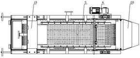
FIG. 2 is a schematic top view of a drilling mud screening device;
FIG. 3 is a schematic diagram of the construction of a screen of the drilling mud screening device;
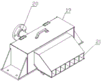
FIG. 4 is a schematic diagram of the structure of the feed box of the drilling mud screening device;
FIG. 5 is a schematic diagram of the construction of the air knives of the drilling mud screening device;
FIG. 6 is a schematic diagram of the construction of the drum of the drilling mud screening device;
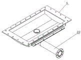
FIG. 7 is a schematic diagram of the vacuum box of the drilling mud screening device;
FIG. 8 is a schematic diagram of the vibrator of the drilling mud screening device;
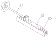
figure 9 is a schematic diagram of the configuration of the tensioners of the drilling fluid mud screening device.
In the figure: 1. the device comprises a frame, 2, a driving roller, 3, a driven roller, 4, a driving motor, 5, a screen, 6, a vacuum box, 7, a tensioner, 8, a roller shaft, 9, a supporting cylinder, 10, a transmission belt pulley, 11, an upper air knife, 12, a lower air knife, 13, an air knife body, 14, an installation adjusting plate, 15, an installation rod, 16, a connecting rod, 17, an installation hole, 18, an air flow port, 19, a feeding box, 20, a feeding pipe, 21, a liquid separating tank, 22, a connecting pipe, 23, a vibrating plate, 24, a vibrating motor, 25, a sliding rail, 26, an installation plate, 27, an adjusting screw rod, 28, a collecting box, 29 and an angle adjusting hole.
Detailed Description
The drilling fluid mud screening device comprises a frame 1, a driving roller 2, a driven roller 3, a driving motor 4, a screen 5 and a vacuum box 6; one end of the frame 1 is provided with a driving roller 2, and the frame 1 at one side of the driving roller 2 is provided with a collecting box 28. A driving motor 4 is arranged on the rack 1 at the other side of the driving roller 2, and the driving motor 4 is connected with the driving roller 2 through a speed reducer; the other end of the frame 1 is provided with the driven roller 3 through a tensioner 7, the tensioner 7 is composed of a slide rail 25, a mounting plate 26 and an adjusting screw 27, the mounting plate 26 is slidably mounted on the slide rail, the adjusting screw 27 is arranged on the mounting plate 26, and the adjusting screw 27 is connected with the frame 1 through a screw nut. The screen 5 is arranged on the driving roller 2 and the driven roller 3.
The driving roller 2 and the driven roller 3 are respectively composed of a roller shaft 8, a supporting cylinder 9 and a transmission belt pulley 10, the supporting cylinder 9 is fixedly installed on the roller shaft 8, a rubber anti-skid layer is arranged on the circumferential surface of the supporting cylinder 9, and anti-skid grains are arranged on the anti-skid layer. A transmission belt pulley 10 is fixedly arranged on the drum shaft 8 at two sides of the supporting cylinder 9, a belt groove is arranged on the circumference of the transmission belt pulley 10, and the screen 5 is an annular screen; triangular transmission belts are fixedly arranged on two sides of the screen 5. The screen 5 is connected with the driving roller 2 and the driven roller 3 through the matching of a triangular transmission belt and a belt groove.
An upper air knife 11 is arranged on one side above the driving roller 2 through the frame 1, and a lower air knife 12 is arranged on one side below the driving roller 2 through the frame 1. The upper air knife 11 and the lower air knife 12 are respectively composed of an air knife body 13, an installation adjusting plate 14, an installation rod 15 and a connecting rod 16, the installation adjusting plate 14 is symmetrically arranged, an installation hole 17 and a plurality of angle adjusting holes 29 are formed in the installation adjusting plate 14, and the angle adjusting holes 29 are arranged in a fan shape. An installation rod 15 is fixedly installed between the installation adjusting plates 14, an air knife body 13 is fixedly installed on the installation rod 15 through a connecting rod 16, the air knife body 13 is hollow and long-strip-shaped, the cross section of the air knife body 13 is conical, an air flow opening 18 is formed in the front end of the air knife body 13, and the air knife body 13 is communicated with a high-pressure air source through a communicating pipe. The purpose of the angle adjusting hole 29 is to adjust the angle of the adjusting plate 14, and thus the working angle of the wind-mounting blade body 13.
A feeding box 19 is arranged above the driven roller 3 through the frame 1; the feeding box 19 is a rectangular body, a top cover is arranged at the top of the feeding box 19, a feeding pipe 20 is arranged on one side of the feeding box 19, a plurality of liquid separating tanks 21 are arranged on the other side of the feeding box 19, and the feeding pipe 20 and the liquid separating tanks 21 are respectively communicated with the feeding box 19. The purpose of the diversion channel 21 is to provide for a uniform outflow of drilling mud and to prevent longitudinal accumulation of drilling mud on the screen 5.
The screen cloth 5 lower surface between driving drum 2 and the driven drum 3 is equipped with vacuum box 6 through frame 1, and vacuum box 6 is four pyramid shape bodies, and vacuum box 6's top is uncovered form, and vacuum box 6's bottom is provided with connecting pipe 22, and vacuum box 6's top is provided with the rectangle sealing strip, and vacuum box 6 passes through sealing strip and screen cloth 5 lower surface sliding seal and is connected. As an improvement, a rectangular sealing groove can be arranged at the top of the vacuum box 6, sealing water is placed in the sealing groove, and the vacuum box 6 is sealed with the lower surface of the screen 5 in a water-tight mode. The vacuum box 6 is communicated with a vacuum device through a connecting pipe 22; the vacuum device is a liquid ring vacuum pump.
The vacuum box 6 is provided with a vibrator, the vibrator is composed of a vibrating plate 23 and a vibrating motor 24, the vibrating plate 23 is a latticed rectangular body, and the vibrating motor 24 is fixedly arranged on the lower surface of the vibrating plate 23. The vibrator is connected in sliding contact with the surface of the under-screen 5 through a vibration plate 23.
When the vibrating screen for the drilling fluid mud works, the drilling fluid mud returned from a shaft is firstly pumped into a feeding box 19 of the vibrating screen from a collecting pool and is distributed to a screen mesh 5 through a liquid separating groove 21 of the feeding box 19. In the process that the drilling fluid mud is distributed to the screen 5 from the liquid distribution groove 21 of the feeding box 19, the discharge amount of the drilling fluid mud is controlled through the adjusting flashboards on the liquid distribution groove 21, and then the paving thickness of the drilling fluid mud on the screen 5 is controlled to be 10-30 mm.
In the process of distributing drilling fluid mud onto the screen 5 from the liquid distributing groove 21 of the feeding box 19, the rotating speed of the screen 5 is controlled within the range of 0.05 to 0.168m/s, the vibration motor 24 is started, and the vibration frequency of the vibration motor is controlled within the range of 5000 to 7700Hz, so that the vibration motor 24 drives the screen 5 to vibrate through the vibration plate 23.
The vibration plate 23 drives the screen 5 to vibrate, and simultaneously, the vacuum device is started, and the vacuum degree is controlled within the range of 20KPa to 60KPa, so that the vacuum device acts on the screen 5 through the vacuum box 6, and the moisture, the harmful gas and the volatile substances in the drilling fluid mud are adsorbed and dried; the vacuum device is used for removing water and harmful gases ( Etc.) and volatile substances (petroleum hydrocarbon compounds, benzene series (toluene, ethylbenzene, xylene) are adsorbed into a vacuum device, and then harmful gas and volatile substances are separated from a liquid phase; and is discharged through an exhaust port to be subjected to combustion treatment; the absorbed moisture and part of solid phase with small grain diameter are pumped into a collecting pool through a return pipe and enter the next working cycle;
in the working process of the vacuum device, drilling fluid mud (filter cake) which is dried on the screen 5 continues to move forward along with the screen 5, when the drilling fluid mud moves to the position of the air knife 11, the air knife 11 starts to work, in the process, the working angle of the air knife 11 is controlled within the range of 20-45 degrees, the air speed of the air knife is controlled within the range of 510-1650L/min, the running speed of the drilling fluid mud is reduced, the drilling fluid mud rolls on the screen 5, and the drilling fluid mud (filter cake) is blown and dried again;
the drilling fluid mud (filter cake) after the secondary drying treatment continues to move forward along with the screen 5 and drops into the collecting box 28 for collection and centralized treatment, and when the screen 5 after unloading the drilling fluid mud (filter cake) moves to the position of the lower air knife 12; the lower air knife 12 starts to work, and residual slurry in meshes of the screen 5 is cleaned to ensure the permeability of the meshes of the screen 5, in the process, the working angle of the lower air knife 12 is controlled within the range of 5-10 degrees, and the air speed of the air knife is controlled within the range of 510-1650L/min; the screen 5 after the mesh is cleaned continuously rotates, and when the screen 5 after the cleaning is moved to the position of the feeding box 19, the drilling fluid slurry in the feeding box 19 is shunted to the screen 5 after the cleaning through the diversion tank 21; thereby entering the next duty cycle. The vibrating screen can realize effective treatment of different mud and sludge by adjusting the vacuum degree in the vacuum box 6. Through the regulation to the angle of giving vent to anger and the tolerance of last air knife 11, can carry out the blowback to different kinds of materials on screen cloth 5, improve the mummification effect of mud to can clear up the material that blocks up, the adhesion on screen cloth 5 well through lower air knife 12, keep the cleanness of screen cloth 5. Has positive significance for reducing the harm of the drill cuttings to the atmosphere and the operating environment.
Claims (3)
1. A vibrating screen for drilling fluid mud comprises a frame (1), a driving roller (2), a driven roller (3), a driving motor (4), a screen (5) and a vacuum box (6); the method is characterized in that: one end of the rack (1) is provided with a driving roller (2), the rack (1) on one side of the driving roller (2) is provided with a driving motor (4), and the driving motor (4) is connected with the driving roller (2) through a speed reducer; the other end of the rack (1) is provided with a driven roller (3) through a tensioner (7), the driving roller (2) and the driven roller (3) are provided with a screen (5), one side above the driving roller (2) is provided with an upper air knife (11) through the rack (1), and one side below the driving roller (2) is provided with a lower air knife (12) through the rack (1); the upper air knife (11) and the lower air knife (12) are respectively composed of an air knife body (13), an installation adjusting plate (14), an installation rod (15) and a connecting rod (16), the installation adjusting plate (14) is symmetrically arranged, and an installation hole (17) and a plurality of angle adjusting holes (29) are formed in the installation adjusting plate (14); an installation rod (15) is fixedly arranged between the installation adjusting plates (14), an air knife body (13) is fixedly arranged on the installation rod (15) through a connecting rod (16), and the air knife body (13) is communicated with a high-pressure air source; the angle adjusting holes (29) are arranged in a sector shape; the wind knife body (13) is a hollow strip, the section of the wind knife body is conical, and the front end of the wind knife body (13) is provided with an airflow port (18); a feeding box (19) is arranged above the driven roller (3) through the frame (1); the lower surface of the screen (5) between the driving roller (2) and the driven roller (3) is provided with a vacuum box (6) through a rack (1), the vacuum box (6) is a quadrangular pyramid, the top of the vacuum box (6) is open, the bottom of the vacuum box (6) is provided with a connecting pipe (22), the top of the vacuum box (6) is provided with a rectangular sealing strip, the vacuum box (6) is connected with the lower surface of the screen (5) in a sliding and sealing manner through the sealing strip, and the screen (5) is an annular screen; triangular transmission belts are fixedly arranged on two sides of the screen (5), a vibrator is arranged in the vacuum box (6), the vibrator is composed of a vibrating plate (23) and a vibrating motor (24), the vibrating plate (23) is a latticed rectangular body, and the vibrating motor (24) is fixedly arranged on the lower surface of the vibrating plate (23); the vibrator is connected with the lower surface of the screen (5) in a sliding contact manner through a vibrating plate (23); a feeding box (19) is arranged above the driven roller (3) through the rack (1), the feeding box (19) is a rectangular body, a top cover is arranged at the top of the feeding box (19), a feeding pipe (20) is arranged on one side of the feeding box (19), a plurality of liquid separating grooves (21) are arranged on the other side of the feeding box (19), and the feeding pipe (20) and the liquid separating grooves (21) are respectively communicated with the feeding box (19); the vacuum box (6) is communicated with the vacuum device through a communicating pipe, and the front end of the frame (1) is provided with a collecting box (28); the vacuum device is a liquid ring vacuum pump;
the working process of the vibrating screen comprises the following steps:
1) Firstly, pumping drilling fluid mud returned from a shaft into a feeding box (19) of the vibrating screen from a collecting pool, and shunting the drilling fluid mud onto a screen (5) through a liquid separating groove (21) of the feeding box (19);
2) During the process that the drilling fluid mud is shunted to the screen (5) from the liquid separating groove (21) of the feeding box (19), the discharge amount of the drilling fluid mud is controlled through the adjusting gate plate on the liquid separating groove (21), and further the paving thickness of the drilling fluid mud on the screen (5) is controlled to be 10-30 mm;
3) In the process of shunting drilling fluid mud onto the screen (5) from a liquid separating groove (21) of the feeding box (19), simultaneously controlling the rotating speed of the screen (5) within the range of 0.05 to 0.168m/s, starting the vibration motor (24), and controlling the vibration frequency of the vibration motor within the range of 5000-7700 Hz so that the vibration motor (24) drives the screen (5) to vibrate through the vibration plate (23);
4) The vacuum device is started while the vibrating plate (23) drives the screen (5) to vibrate, and the vacuum degree is controlled to be in the range of 20KPa to 60KPa, so that the vacuum device acts on the screen (5) through the vacuum box (6), and therefore, the water, harmful gases and volatile substances in the drilling fluid mud are adsorbed, and the drilling fluid mud is dried;
5) After the vacuum device absorbs water, harmful gases and volatile substances in the drilling fluid mud into the vacuum device, the harmful gases and the volatile substances are separated from a liquid phase; and is discharged through an exhaust port for combustion treatment; the adsorbed water and part of solid phase with fine particle size are pumped into a collecting pool through a return pipe and enter the next working cycle;
6) During the working process of the vacuum device, the dried drilling fluid slurry on the screen (5) continues to move forward along with the screen (5);
7) When the drilling fluid mud moves to the position of the upper air knife (11), the upper air knife (11) starts to work;
8) In the process, the working angle of the upper air knife (11) is controlled within the range of 20-45 degrees, the air speed of the air knife is controlled within the range of 510-1650L/min, so that the running speed of the drilling fluid mud is reduced, and the drilling fluid mud is rolled on the screen (5), so that the drilling fluid mud is subjected to blowing and drying treatment again;
9) The drilling fluid mud after the secondary drying treatment continues to move forward along with the screen (5) and falls into a collecting box (28) for collection and centralized treatment, and the screen (5) after the drilling fluid mud is unloaded runs to the position of a lower air knife (12); the lower air knife (12) is started to work, and residual slurry in meshes of the screen (5) is cleaned to ensure the permeability of the meshes of the screen (5);
10 In the process, the working angle of the lower air knife (12) is controlled within the range of 5-10 degrees, and the air speed of the air knife is controlled within the range of 510-1650L/min; the screen (5) with the cleaned mesh continuously rotates;
11 When the cleaned screen (5) runs to the position of the feeding box (19), the drilling fluid slurry in the feeding box (19) is shunted to the cleaned screen (5) through the shunting groove (21); thereby entering the next duty cycle.
2. A shaker for drilling fluid mud as claimed in claim 1 wherein: the driving roller (2) and the driven roller (3) are respectively composed of a roller shaft (8), a supporting cylinder (9) and a transmission belt pulley (10), the supporting cylinder (9) is fixedly arranged on the roller shaft (8), the transmission belt pulley (10) is fixedly arranged on the roller shafts (8) at two sides of the supporting cylinder (9), a belt groove is formed in the circumference of the transmission belt pulley (10), and the screen (5) is connected with the driving roller (2) and the driven roller (3) through the matching of a triangular transmission belt and the belt groove; the circumferential surface of the supporting cylinder (9) is provided with a rubber anti-skid layer, and anti-skid lines are arranged on the anti-skid layer.
3. A shaker for drilling fluid mud as claimed in claim 1, wherein: tensioner (7) constitute by slide rail (25), mounting panel (26) and adjustment screw (27), slidable mounting has mounting panel (26) on slide rail (25), is provided with adjustment screw (27) on mounting panel (26), adjustment screw (27) are connected with frame (1) through the screw-nut.
Priority Applications (1)
| Application Number | Priority Date | Filing Date | Title |
|---|---|---|---|
| CN201710318443.9A CN106955840B (en) | 2017-05-08 | 2017-05-08 | Vibrating screen for drilling fluid mud |
Applications Claiming Priority (1)
| Application Number | Priority Date | Filing Date | Title |
|---|---|---|---|
| CN201710318443.9A CN106955840B (en) | 2017-05-08 | 2017-05-08 | Vibrating screen for drilling fluid mud |
Publications (2)
| Publication Number | Publication Date |
|---|---|
| CN106955840A CN106955840A (en) | 2017-07-18 |
| CN106955840B true CN106955840B (en) | 2023-02-03 |
Family
ID=59483003
Family Applications (1)
| Application Number | Title | Priority Date | Filing Date |
|---|---|---|---|
| CN201710318443.9A Active CN106955840B (en) | 2017-05-08 | 2017-05-08 | Vibrating screen for drilling fluid mud |
Country Status (1)
| Country | Link |
|---|---|
| CN (1) | CN106955840B (en) |
Families Citing this family (6)
| Publication number | Priority date | Publication date | Assignee | Title |
|---|---|---|---|---|
| CN112516661B (en) * | 2021-01-21 | 2023-05-30 | 成都西部石油装备股份有限公司 | Electric high-frequency vibration negative pressure sieve bed |
| CN112696161B (en) * | 2021-03-24 | 2021-06-29 | 西南石油大学 | Negative pressure generating and gas-liquid separating integrated negative pressure well drilling vibrating screen |
| CN113663898A (en) * | 2021-05-21 | 2021-11-19 | 康明克斯(北京)机电设备有限公司 | A perforated rubber conveyor belt separator with vibrator |
| CN114458196B (en) * | 2021-08-02 | 2024-01-02 | 中海油能源发展股份有限公司 | Drilling rock debris vacuum reduction treatment device and treatment method thereof |
| CN116752917B (en) * | 2023-08-17 | 2023-12-19 | 河南中正石油起重机械有限公司 | Negative pressure shale shaker for well drilling |
| CN119195676B (en) * | 2024-12-02 | 2025-02-25 | 河南中正石油起重机械有限公司 | A drilling fluid vibrating screen that is easy to disassemble and clean |
Citations (10)
| Publication number | Priority date | Publication date | Assignee | Title |
|---|---|---|---|---|
| US4255269A (en) * | 1979-05-24 | 1981-03-10 | Bernardus Timmer | Method and apparatus for adapting the composition of a drilling fluid for use in making a hole in the earth by rotary drilling |
| US4350591A (en) * | 1980-10-20 | 1982-09-21 | Lee Joseph E | Drilling mud cleaning apparatus |
| US4750920A (en) * | 1986-06-30 | 1988-06-14 | Ramteck Systems, Inc. | Single pass mud rejuvenation system and method |
| US6223906B1 (en) * | 1997-10-03 | 2001-05-01 | J. Terrell Williams | Flow divider box for conducting drilling mud to selected drilling mud separation units |
| CN201253604Y (en) * | 2008-07-02 | 2009-06-10 | 尹庆文 | Self-cleaning vibration screen |
| CN102187051A (en) * | 2008-10-29 | 2011-09-14 | 丹尼尔·盖·波默洛 | System and method for drying drill cuttings |
| CN202810723U (en) * | 2012-04-27 | 2013-03-20 | 青岛泰众能源技术有限公司 | Drilling liquid solid-phase separation equipment |
| CN105781455A (en) * | 2016-05-03 | 2016-07-20 | 长江大学 | Drilling fluid recovery and solid control device |
| CN205907169U (en) * | 2016-08-24 | 2017-01-25 | 宁波鑫涌环保技术有限公司 | Flat link chain formula mud mummification machine |
| CN206701701U (en) * | 2017-05-08 | 2017-12-05 | 长江大学 | A kind of vibratory sieve for drilling fluid mud |
-
2017
- 2017-05-08 CN CN201710318443.9A patent/CN106955840B/en active Active
Patent Citations (10)
| Publication number | Priority date | Publication date | Assignee | Title |
|---|---|---|---|---|
| US4255269A (en) * | 1979-05-24 | 1981-03-10 | Bernardus Timmer | Method and apparatus for adapting the composition of a drilling fluid for use in making a hole in the earth by rotary drilling |
| US4350591A (en) * | 1980-10-20 | 1982-09-21 | Lee Joseph E | Drilling mud cleaning apparatus |
| US4750920A (en) * | 1986-06-30 | 1988-06-14 | Ramteck Systems, Inc. | Single pass mud rejuvenation system and method |
| US6223906B1 (en) * | 1997-10-03 | 2001-05-01 | J. Terrell Williams | Flow divider box for conducting drilling mud to selected drilling mud separation units |
| CN201253604Y (en) * | 2008-07-02 | 2009-06-10 | 尹庆文 | Self-cleaning vibration screen |
| CN102187051A (en) * | 2008-10-29 | 2011-09-14 | 丹尼尔·盖·波默洛 | System and method for drying drill cuttings |
| CN202810723U (en) * | 2012-04-27 | 2013-03-20 | 青岛泰众能源技术有限公司 | Drilling liquid solid-phase separation equipment |
| CN105781455A (en) * | 2016-05-03 | 2016-07-20 | 长江大学 | Drilling fluid recovery and solid control device |
| CN205907169U (en) * | 2016-08-24 | 2017-01-25 | 宁波鑫涌环保技术有限公司 | Flat link chain formula mud mummification machine |
| CN206701701U (en) * | 2017-05-08 | 2017-12-05 | 长江大学 | A kind of vibratory sieve for drilling fluid mud |
Also Published As
| Publication number | Publication date |
|---|---|
| CN106955840A (en) | 2017-07-18 |
Similar Documents
| Publication | Publication Date | Title |
|---|---|---|
| CN106955840B (en) | Vibrating screen for drilling fluid mud | |
| CN106939773B (en) | A kind of drilling fluid mud screening drying method for treating and drilling fluid mud screening plant | |
| CN111804724B (en) | Soil restoration ecological moisturizing method based on efficient stirring | |
| CN107497580B (en) | Sand and stone production line | |
| CA2966916C (en) | Rotary vacuum and screen system and methods for separating solids and liquids | |
| CN111842459A (en) | Ecological moisturizing system of soil remediation | |
| CN107716538B (en) | Soil ectopic repair system and repair method thereof | |
| CN113152554A (en) | Emergency rescue equipment for collapse of building | |
| CN113123383A (en) | Gas-solid separation device of emergency rescue equipment and emergency rescue equipment thereof | |
| CN105370228A (en) | Slurry nonlanding intelligent environment-friendly integral well drilling solid control system | |
| CN115671872A (en) | Polluted bottom mud and solid pollutant separation equipment | |
| CN205100913U (en) | Mud does not fall to ground intelligent environmental protection integration well drilling solid controlling system | |
| CN112427440B (en) | Cement waste treatment regenerating unit | |
| CN210817295U (en) | Regeneration system capable of recycling steel casting water glass waste sand | |
| CN206701701U (en) | A kind of vibratory sieve for drilling fluid mud | |
| WO2022178883A1 (en) | Underground leachate sewage treatment equipment | |
| CN214883967U (en) | Suction excavation robot and emergency rescue equipment thereof | |
| CN105971108A (en) | Powerful suction-type sewer scavenger | |
| CN211972103U (en) | A sewage treatment tank sludge treatment device | |
| KR101097880B1 (en) | Float removal equipment for water level control | |
| CN220310662U (en) | Building construction grit breaker | |
| CN206304522U (en) | A kind of paint retracting device | |
| CN211677922U (en) | Be used for industry to peel off residue processing apparatus | |
| JP6004529B2 (en) | Mud treatment system | |
| CN223819134U (en) | Multi-element linkage grain dust remover |
Legal Events
| Date | Code | Title | Description |
|---|---|---|---|
| PB01 | Publication | ||
| PB01 | Publication | ||
| SE01 | Entry into force of request for substantive examination | ||
| SE01 | Entry into force of request for substantive examination | ||
| GR01 | Patent grant | ||
| GR01 | Patent grant |