CN107294167B - Voltage equalization method, cell equalization control circuit and cell equalization circuit - Google Patents
Voltage equalization method, cell equalization control circuit and cell equalization circuit Download PDFInfo
- Publication number
- CN107294167B CN107294167B CN201710564786.3A CN201710564786A CN107294167B CN 107294167 B CN107294167 B CN 107294167B CN 201710564786 A CN201710564786 A CN 201710564786A CN 107294167 B CN107294167 B CN 107294167B
- Authority
- CN
- China
- Prior art keywords
- voltage
- battery unit
- battery
- capacitor
- cell
- Prior art date
- Legal status (The legal status is an assumption and is not a legal conclusion. Google has not performed a legal analysis and makes no representation as to the accuracy of the status listed.)
- Active
Links
Images


Classifications
-
- H—ELECTRICITY
- H02—GENERATION; CONVERSION OR DISTRIBUTION OF ELECTRIC POWER
- H02J—ELECTRIC POWER NETWORKS; CIRCUIT ARRANGEMENTS OR SYSTEMS FOR SUPPLYING OR DISTRIBUTING ELECTRIC POWER; SYSTEMS FOR STORING ELECTRIC ENERGY
- H02J7/00—Circuit arrangements for charging or discharging batteries or for supplying loads from batteries
- H02J7/50—Circuit arrangements for charging or discharging batteries or for supplying loads from batteries acting upon multiple batteries simultaneously or sequentially
- H02J7/52—Circuit arrangements for charging or discharging batteries or for supplying loads from batteries acting upon multiple batteries simultaneously or sequentially for charge balancing, e.g. equalisation of charge between batteries
- H02J7/54—Passive balancing, e.g. using resistors or parallel MOSFETs
-
- H—ELECTRICITY
- H02—GENERATION; CONVERSION OR DISTRIBUTION OF ELECTRIC POWER
- H02J—ELECTRIC POWER NETWORKS; CIRCUIT ARRANGEMENTS OR SYSTEMS FOR SUPPLYING OR DISTRIBUTING ELECTRIC POWER; SYSTEMS FOR STORING ELECTRIC ENERGY
- H02J7/00—Circuit arrangements for charging or discharging batteries or for supplying loads from batteries
- H02J7/50—Circuit arrangements for charging or discharging batteries or for supplying loads from batteries acting upon multiple batteries simultaneously or sequentially
- H02J7/52—Circuit arrangements for charging or discharging batteries or for supplying loads from batteries acting upon multiple batteries simultaneously or sequentially for charge balancing, e.g. equalisation of charge between batteries
-
- H—ELECTRICITY
- H01—ELECTRIC ELEMENTS
- H01M—PROCESSES OR MEANS, e.g. BATTERIES, FOR THE DIRECT CONVERSION OF CHEMICAL ENERGY INTO ELECTRICAL ENERGY
- H01M10/00—Secondary cells; Manufacture thereof
- H01M10/42—Methods or arrangements for servicing or maintenance of secondary cells or secondary half-cells
- H01M10/425—Structural combination with electronic components, e.g. electronic circuits integrated to the outside of the casing
-
- H—ELECTRICITY
- H01—ELECTRIC ELEMENTS
- H01M—PROCESSES OR MEANS, e.g. BATTERIES, FOR THE DIRECT CONVERSION OF CHEMICAL ENERGY INTO ELECTRICAL ENERGY
- H01M10/00—Secondary cells; Manufacture thereof
- H01M10/42—Methods or arrangements for servicing or maintenance of secondary cells or secondary half-cells
- H01M10/44—Methods for charging or discharging
- H01M10/441—Methods for charging or discharging for several batteries or cells simultaneously or sequentially
-
- H—ELECTRICITY
- H02—GENERATION; CONVERSION OR DISTRIBUTION OF ELECTRIC POWER
- H02J—ELECTRIC POWER NETWORKS; CIRCUIT ARRANGEMENTS OR SYSTEMS FOR SUPPLYING OR DISTRIBUTING ELECTRIC POWER; SYSTEMS FOR STORING ELECTRIC ENERGY
- H02J7/00—Circuit arrangements for charging or discharging batteries or for supplying loads from batteries
- H02J7/50—Circuit arrangements for charging or discharging batteries or for supplying loads from batteries acting upon multiple batteries simultaneously or sequentially
- H02J7/52—Circuit arrangements for charging or discharging batteries or for supplying loads from batteries acting upon multiple batteries simultaneously or sequentially for charge balancing, e.g. equalisation of charge between batteries
- H02J7/56—Active balancing, e.g. using capacitor-based, inductor-based or DC-DC converters
-
- H—ELECTRICITY
- H02—GENERATION; CONVERSION OR DISTRIBUTION OF ELECTRIC POWER
- H02J—ELECTRIC POWER NETWORKS; CIRCUIT ARRANGEMENTS OR SYSTEMS FOR SUPPLYING OR DISTRIBUTING ELECTRIC POWER; SYSTEMS FOR STORING ELECTRIC ENERGY
- H02J7/00—Circuit arrangements for charging or discharging batteries or for supplying loads from batteries
- H02J7/50—Circuit arrangements for charging or discharging batteries or for supplying loads from batteries acting upon multiple batteries simultaneously or sequentially
- H02J7/575—Parallel/serial switching of connection of batteries to charge or load circuit
-
- H—ELECTRICITY
- H01—ELECTRIC ELEMENTS
- H01M—PROCESSES OR MEANS, e.g. BATTERIES, FOR THE DIRECT CONVERSION OF CHEMICAL ENERGY INTO ELECTRICAL ENERGY
- H01M10/00—Secondary cells; Manufacture thereof
- H01M10/42—Methods or arrangements for servicing or maintenance of secondary cells or secondary half-cells
- H01M10/425—Structural combination with electronic components, e.g. electronic circuits integrated to the outside of the casing
- H01M2010/4271—Battery management systems including electronic circuits, e.g. control of current or voltage to keep battery in healthy state, cell balancing
-
- Y—GENERAL TAGGING OF NEW TECHNOLOGICAL DEVELOPMENTS; GENERAL TAGGING OF CROSS-SECTIONAL TECHNOLOGIES SPANNING OVER SEVERAL SECTIONS OF THE IPC; TECHNICAL SUBJECTS COVERED BY FORMER USPC CROSS-REFERENCE ART COLLECTIONS [XRACs] AND DIGESTS
- Y02—TECHNOLOGIES OR APPLICATIONS FOR MITIGATION OR ADAPTATION AGAINST CLIMATE CHANGE
- Y02E—REDUCTION OF GREENHOUSE GAS [GHG] EMISSIONS, RELATED TO ENERGY GENERATION, TRANSMISSION OR DISTRIBUTION
- Y02E60/00—Enabling technologies; Technologies with a potential or indirect contribution to GHG emissions mitigation
- Y02E60/10—Energy storage using batteries
Landscapes
- Engineering & Computer Science (AREA)
- Power Engineering (AREA)
- Manufacturing & Machinery (AREA)
- Chemical & Material Sciences (AREA)
- Chemical Kinetics & Catalysis (AREA)
- Electrochemistry (AREA)
- General Chemical & Material Sciences (AREA)
- Microelectronics & Electronic Packaging (AREA)
- Charge And Discharge Circuits For Batteries Or The Like (AREA)
- Secondary Cells (AREA)
Abstract
公开了一种电压均衡方法及电池均衡控制电路、电池均衡电路。电压均衡方法包括在每个开关周期的第一时间段内,依据第一电池单元与浮充电容上的电压大小来使第一电池单元对浮充电容充电或来使浮充电容对第一电池单元放电;以及在每个开关周期的第二时间段内,依据第二电池单元与浮充电容上的电压大小来使第二电池单元对浮充电容充电或来使浮充电容对第二电池单元放电。利用本发明提出的电压均衡方法可以高效地对不同电池单元上的电压进行均衡,延长了电池单元寿命且提高了系统工作效率。
A voltage equalization method, a battery equalization control circuit, and a battery equalization circuit are disclosed. The voltage equalization method includes, in a first time period of each switching cycle, charging the first battery unit to the floating capacitor or causing the floating capacitor to charge the first battery according to the magnitude of the voltage on the first battery unit and the floating capacitor. discharging the cell; and in the second period of each switching cycle, charging the second battery cell to the floating capacitor or causing the floating capacitor to charge the second battery according to the magnitude of the voltage on the second battery cell and the floating capacitor Unit discharges. The voltage equalization method proposed by the present invention can efficiently equalize the voltages on different battery cells, prolong the life of the battery cells and improve the working efficiency of the system.
Description
技术领域technical field
本发明涉及电子电路,更具体地,涉及电池均衡电路及方法。The present invention relates to electronic circuits, and more particularly, to cell balancing circuits and methods.
背景技术Background technique
在多节电池单元串联的电池包或电池管理系统中,当电池单元上的电压不相等时,即电压不均衡时,会缩短电池单元寿命并降低电池包的容量,因此有必要对电池单元进行电压均衡以确保系统安全工作及系统的稳定性。In a battery pack or battery management system with multiple battery cells connected in series, when the voltages on the battery cells are not equal, that is, when the voltages are unbalanced, the life of the battery cells will be shortened and the capacity of the battery pack will be reduced. Voltage equalization to ensure the safe operation of the system and the stability of the system.
发明内容SUMMARY OF THE INVENTION
依据本发明实施例的一个方面,提出了一种利用浮充电容对第一电池单元和第二电池单元进行电压均衡的方法。该包括:在每个开关周期的第一时间段内,依据第一电池单元与浮充电容上的电压大小来使第一电池单元对浮充电容充电或来使浮充电容对第一电池单元放电;以及在所述开关周期的第二时间段内,依据第二电池单元与浮充电容上的电压大小来使第二电池单元对浮充电容充电或来使浮充电容对第二电池单元放电。According to an aspect of the embodiments of the present invention, a method for voltage equalization of a first battery unit and a second battery unit by using a floating capacitor is provided. The method includes: in the first time period of each switching cycle, according to the magnitude of the voltage on the first battery unit and the floating capacitor, the first battery unit is charged to the floating capacitor or the floating capacitor is charged to the first battery unit discharging; and during the second time period of the switching cycle, charging the second battery unit to the floating capacitor or causing the floating capacitor to charge the second battery unit according to the magnitude of the voltage on the second battery unit and the floating capacitor discharge.
依据本发明实施例的又一个方面,提出了一种电池均衡控制电路。该电池均衡控制电路利用浮充电容对第一电池单元和第二电池单元进行电压均衡。电池均衡控制电路包括第一开关电路和第二开关电路,其中,在每个开关周期的第一时间段内,第一开关电路形成通路且第二开关电路断开通路以依据第一电池单元与浮充电容上的电压大小来使第一电池单元对浮充电容充电或来使浮充电容对第一电池单元放电;在每个开关周期的第二时间段内,第一开关电路断开通路且第二开关电路形成通路以依据第二电池单元与浮充电容上的电压大小来使第二电池单元对浮充电容充电或来使浮充电容对第二电池单元放电。According to yet another aspect of the embodiments of the present invention, a battery balancing control circuit is provided. The battery equalization control circuit utilizes a floating capacitor to perform voltage equalization on the first battery unit and the second battery unit. The cell balancing control circuit includes a first switch circuit and a second switch circuit, wherein, during a first period of each switching cycle, the first switch circuit forms a path and the second switch circuit opens the path according to the relationship between the first battery cell and the second switch circuit. The magnitude of the voltage on the float capacitor to enable the first battery cell to charge the float capacitor or to discharge the float capacitor to the first battery cell; during the second time period of each switching cycle, the first switching circuit opens the path And the second switch circuit forms a path to make the second battery unit charge the float capacitor or discharge the float capacitor to the second battery unit according to the magnitude of the voltage on the second battery unit and the float capacitor.
依据本发明实施例的又一个方面,提出了一种电池均衡电路。电池均衡电路包括:第一电池单元和第二电池单元;浮充电容,其中,电池均衡电路利用浮充电容对第一电池单元和第二电池单元进行电压均衡;以及电池均衡控制电路。其中,电池均衡控制电路包括第一开关电路和第二开关电路,其中,在每个开关周期的第一时间段内,第一开关电路形成通路且第二开关电路断开通路以依据第一电池单元与浮充电容上的电压大小来使第一电池单元对浮充电容充电或来使浮充电容对第一电池单元放电;在每个开关周期的第二时间段内,第一开关电路断开通路且第二开关电路形成通路以依据第二电池单元与浮充电容上的电压大小来使第二电池单元对浮充电容充电或来使浮充电容对第二电池单元放电。According to yet another aspect of the embodiments of the present invention, a battery balancing circuit is provided. The battery balancing circuit includes: a first battery unit and a second battery unit; a floating capacitor, wherein the battery balancing circuit uses the floating capacitor to balance the voltage of the first battery unit and the second battery unit; and a battery balancing control circuit. Wherein, the battery balancing control circuit includes a first switch circuit and a second switch circuit, wherein, in a first time period of each switching cycle, the first switch circuit forms a path and the second switch circuit opens the path to adjust the path according to the first battery The magnitude of the voltage on the cell and the floating capacitor enables the first battery cell to charge the floating capacitor or discharge the floating capacitor to the first battery cell; during the second time period of each switching cycle, the first switching circuit is turned off. The path is opened and the second switch circuit forms a path to make the second battery cell charge the float capacitor or discharge the float capacitor to the second battery cell according to the magnitude of the voltage on the second battery cell and the float capacitor.
依据本发明实施例的又一个方面,提出了一种多电池均衡电路。多电池均衡电路包括N个串联耦接的电池单元,其中,N大于3。其中,每两个相邻的电池单元配置有一个浮充电容和一个电池均衡控制电路。其中,电池均衡控制电路包括第一开关电路和第二开关电路,其中,在每个开关周期的第一时间段内,第一开关电路形成通路且第二开关电路断开通路以依据第一电池单元与浮充电容上的电压大小来使第一电池单元对浮充电容充电或来使浮充电容对第一电池单元放电;在每个开关周期的第二时间段内,第一开关电路断开通路且第二开关电路形成通路以依据第二电池单元与浮充电容上的电压大小来使第二电池单元对浮充电容充电或来使浮充电容对第二电池单元放电。According to yet another aspect of the embodiments of the present invention, a multi-cell balancing circuit is provided. The multi-cell balancing circuit includes N battery cells coupled in series, where N is greater than 3. Wherein, every two adjacent battery cells are configured with a floating capacitor and a battery balance control circuit. Wherein, the battery balancing control circuit includes a first switch circuit and a second switch circuit, wherein, in a first time period of each switching cycle, the first switch circuit forms a path and the second switch circuit disconnects the path according to the first battery The magnitude of the voltage on the cell and the floating capacitor enables the first battery cell to charge the floating capacitor or discharge the floating capacitor to the first battery cell; during the second time period of each switching cycle, the first switching circuit is turned off. The path is opened and the second switch circuit forms a path to make the second battery cell charge the float capacitor or discharge the float capacitor to the second battery cell according to the magnitude of the voltage on the second battery cell and the float capacitor.
利用本发明实施例提出的电压均衡方法、电池均衡控制电路、电池均衡电路和多电池均衡电路,能够利用浮充电容高效地实现对两个电池单元之间的电压均衡。By using the voltage equalization method, battery equalization control circuit, cell equalization circuit and multi-cell equalization circuit proposed in the embodiments of the present invention, the voltage equalization between two battery cells can be efficiently realized by using the floating capacitor.
附图说明Description of drawings
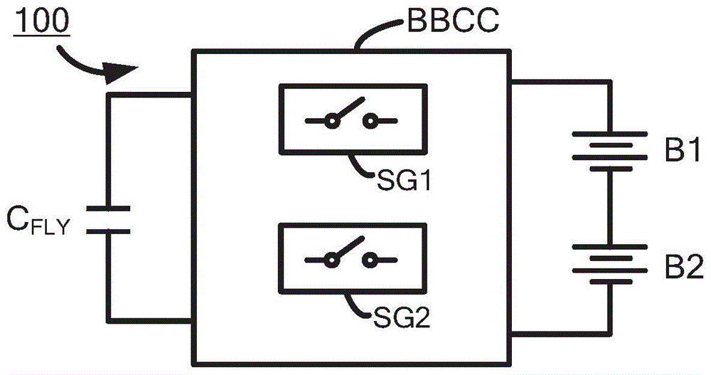
图1示例性地示出依据本发明一实施例的电池均衡电路100。FIG. 1 exemplarily shows a
图2示出依据本发明另一实施例的电池均衡电路200。FIG. 2 shows a
图3(a)~3(b)示出图2所示电池均衡电路200的工作过程。FIGS. 3( a ) to 3 ( b ) illustrate the working process of the
图4示例性地示出依据本发明另一实施例的电池均衡电路400。FIG. 4 exemplarily shows a
图5(a)~5(c)示出图4所示的电池均衡电路400在电池均衡初始阶段时的控制方式和工作过程。FIGS. 5( a ) to 5 ( c ) illustrate the control mode and working process of the
图6(a)~6(c)示出图4所示的电池均衡电路400在非初始阶段中第一电池单元B1上电压大于第二电池单元B2上电压且当第一电池单元B1和第二电池单元B2之间的电压差值大于限流阈值的情形下的控制方式和工作过程。6(a)-6(c) show that the voltage on the first battery unit B1 is greater than the voltage on the second battery unit B2 in the non-initial stage of the
图7(a)~7(c)示出图4所示的电池均衡电路400在非初始阶段中第二电池单元B2上电压大于第一电池单元B1上电压且当第二电池单元B2和第一电池单元B1之间的电压差值大于限流阈值的情形下的控制原理和工作过程。FIGS. 7( a ) to 7 ( c ) show that the voltage on the second battery unit B2 is greater than the voltage on the first battery unit B1 in the non-initial stage of the
图8示出依据本发明一实施例的具有4个串联电池单元的电池均衡电路800,以对具有N(N>2)个串联电池单元的电池均衡电路的结构和工作原理进行具体说明。FIG. 8 shows a
图9示例性地示出依据本发明一实施例的电压均衡方法900。FIG. 9 exemplarily shows a
具体实施方式Detailed ways
下面将详细描述本发明的具体实施例,应当注意,这里描述的实施例只用于举例说明,并不用于限制本发明。在以下描述中,为了提供对本发明的透彻理解,阐述了大量特定细节。然而,对于本领域普通技术人员显而易见的是:不必采用这些特定细节来实行本发明。在其他实例中,为了避免混淆本发明,未具体描述公知的电路、材料或方法。The specific embodiments of the present invention will be described in detail below. It should be noted that the embodiments described herein are only used for illustration and are not used to limit the present invention. In the following description, numerous specific details are set forth in order to provide a thorough understanding of the present invention. It will be apparent, however, to one of ordinary skill in the art that these specific details need not be employed to practice the present invention. In other instances, well-known circuits, materials, or methods have not been described in detail in order to avoid obscuring the present invention.
在整个说明书中,对“一个实施例”、“实施例”、“一个示例”或“示例”的提及意味着:结合该实施例或示例描述的特定特征、结构或特性被包含在本发明至少一个实施例中。因此,在整个说明书的各个地方出现的短语“在一个实施例中”、“在实施例中”、“一个示例”或“示例”不一定都指同一实施例或示例。此外,可以以任何适当的组合和、或子组合将特定的特征、结构或特性组合在一个或多个实施例或示例中。此外,本领域普通技术人员应当理解,在此提供的示图都是为了说明的目的,并且示图不一定是按比例绘制的。应当理解,当称“元件”“连接到”或“耦接”到另一元件时,它可以是直接连接或耦接到另一元件或者可以存在中间元件。相反,当称元件“直接连接到”或“直接耦接到”另一元件时,不存在中间元件。相同的附图标记指示相同的元件。这里使用的术语“和/或”包括一个或多个相关列出的项目的任何和所有组合。Throughout this specification, references to "one embodiment," "an embodiment," "an example," or "an example" mean that a particular feature, structure, or characteristic described in connection with the embodiment or example is included in the present invention in at least one embodiment. Thus, appearances of the phrases "in one embodiment," "in an embodiment," "one example," or "an example" in various places throughout this specification are not necessarily all referring to the same embodiment or example. Furthermore, the particular features, structures or characteristics may be combined in any suitable combination and/or subcombination in one or more embodiments or examples. Furthermore, those of ordinary skill in the art will appreciate that the drawings provided herein are for illustrative purposes and that the drawings are not necessarily drawn to scale. It will be understood that when an "element" is referred to as being "connected" or "coupled" to another element, it can be directly connected or coupled to the other element or intervening elements may be present. In contrast, when an element is referred to as being "directly connected" or "directly coupled" to another element, there are no intervening elements present. The same reference numbers refer to the same elements. As used herein, the term "and/or" includes any and all combinations of one or more of the associated listed items.
图1示例性地示出依据本发明一实施例的电池均衡电路100。如图1所示,电池均衡电路100示例性地包括第一电池单元B1和第二电池单元B2、浮充电容CFLY以及电池均衡控制电路BBCC。当第一电池单元B1和第二电池单元B2上的电压不均衡(即不相等)时,电池均衡电路100通过电池均衡控制电路BBCC作用,利用浮充电容CFLY对第一电池单元B1和第二电池单元B2进行电压均衡,即使得第一电池单元B1和第二电池单元B2上的电压相等。具体地,电池均衡控制电路BBCC示例性地包括第一开关电路SG1和第二开关电路SG2。在每个开关周期的第一时间段内,第一开关电路SG1导通且第二开关电路SG2关断以依据第一电池单元B1与浮充电容CFLY上的电压大小来使第一电池单元B1对浮充电容CFLY充电或来使浮充电容CFLY对第一电池单元B1放电。更加具体地,在每个开关周期的第一时间段内,第一开关电路SG1形成通路且第二开关电路SG2断开通路以当第一电池单元B1上的电压大于浮充电容CFLY上的电压时使第一电池单元B1对浮充电容CFLY充电或当第一电池单元B1上的电压小于浮充电容CFLY上的电压时使浮充电容CFLY对第一电池单元B1放电。在每个开关周期的第二时间段内,第一开关电路SG1关断且第二开关电路SG2导通以依据第二电池单元B2与浮充电容CFLY上的电压大小来使第二电池单元B2对浮充电容CFLY充电或来使浮充电容CFLY对第二电池单元B2放电。更加具体地,在每个开关周期的第二时间段内,第一开关电路SG1断开通路且第二开关电路SG2形成通路以当第二电池单元B2上的电压大于浮充电容CFLY上的电压时使第二电池单元B2对浮充电容CFLY充电或当第二电池单元B2上的电压小于浮充电容CFLY上的电压时使浮充电容CFLY对第二电池单元B2放电。FIG. 1 exemplarily shows a
可见,通过浮充电容CFLY的作用,电能在第一电池单元B1和第二电池单元B2之间转移,使得第一电池单元B1和第二电池单元B2之间的电压差渐渐变小,最终趋于为零,即第一电池单元B1和第二电池单元B2的电压最终相等。It can be seen that the electric energy is transferred between the first battery unit B1 and the second battery unit B2 through the action of the floating capacitor C FLY , so that the voltage difference between the first battery unit B1 and the second battery unit B2 gradually becomes smaller, and finally tends to zero, ie the voltages of the first battery cell B1 and the second battery cell B2 are eventually equal.
利用图1所述的电池均衡电路对两个电池单元之间的电压进行均衡具有非常高的效率,可达95%以上。Using the battery balancing circuit described in FIG. 1 to balance the voltage between two battery cells has a very high efficiency, which can reach more than 95%.
在一个实施例中,第一时间段和第二时间段是开关周期的两个互补时段,即第一时间段和第二时间段一起组成一个开关周期。在另一实施例中,开关周期可以包括除第一时间段和第二时间段以外的时间段。In one embodiment, the first time period and the second time period are two complementary time periods of the switching cycle, ie the first time period and the second time period together constitute one switching cycle. In another embodiment, the switching period may include time periods other than the first time period and the second time period.
在一个实施例中,两个电池单元之间的能量转移可在两个电池单元之间达到电压平衡时自动停止,在另一个实施例,可通过设置使能功能来使能或停止电池均衡功能。In one embodiment, the energy transfer between the two battery cells can be automatically stopped when the voltage balance between the two battery cells is reached, in another embodiment, the cell balancing function can be enabled or disabled by setting the enable function .
图2示出依据本发明另一实施例的电池均衡电路200。如图2所示,电池均衡电路200示例性地包括第一电池单元B1和第二电池单元B2、浮充电容CFLY以及电池均衡控制电路BBCC。其中,第一电池单元B1和第二电池单元B2均具有第一端(如正端)和第二端(如负端),第二电池单元B2的第一端耦接至第一电池单元B1的第二端。电池均衡控制电路BBCC示例性地包括第一开关电路和第二开关电路。其中,第一开关电路示例性地包括开关S1和S3,第二开关电路示例性地包括开关S2和S4。开关S1~S4均具有第一端和第二端,开关S1的第一端耦接至第一电池单元B1的正端,开关S2的第一端耦接至第一电池单元B1的负端,开关S3的第一端耦接至第二电池单元B2的正端,开关S4的第一端耦接至第二电池单元B2的负端。浮充电容CFLY具有第一端和第二端,浮充电容CFLY的第一端耦接至开关S1和S2的第二端,浮充电容CFLY的第二端耦接至开关S3和S4的第二端。FIG. 2 shows a
如图3(a)所示,在每个开关周期的第一时间段T1内,第一开关电路形成通路,即开关S1和S3导通且第二开关电路断开通路即开关S2和S4关断,如此,浮充电容CFLY与第一电池单元B1并联,依据第一电池单元B1和浮充电容CFLY上的电压大小,第一电池单元B1对浮充电容CFLY充电或者浮充电容CFLY对第一电池单元B1充电。如图3(b)所示,在每个开关周期的第二时间段T2内,第一开关电路断开通路,即开关S1和S3关断且第二开关电路形成通路,即开关S2和S4导通,如此,浮充电容CFLY与第二电池单元B2并联,依据第二电池单元B2和浮充电容CFLY上的电压大小,第二电池单元B2对浮充电容CFLY充电或者浮充电容CFLY对第二电池单元B2充电。As shown in Fig. 3(a), in the first time period T1 of each switching cycle, the first switch circuit forms a path, that is, switches S1 and S3 are turned on, and the second switch circuit is turned off, that is, switches S2 and S4 are turned off In this way, the floating capacitor C FLY is connected in parallel with the first battery unit B1. According to the voltage on the first battery unit B1 and the floating capacitor C FLY , the first battery unit B1 charges the floating capacitor C FLY or charges the floating capacitor C FLY. C FLY charges the first battery unit B1. As shown in FIG. 3(b), in the second time period T2 of each switching cycle, the first switch circuit opens the path, that is, the switches S1 and S3 are turned off and the second switch circuit forms the path, that is, the switches S2 and S4 In this way, the floating capacitor C FLY is connected in parallel with the second battery unit B2. According to the voltage on the second battery unit B2 and the floating capacitor C FLY , the second battery unit B2 charges or floats the floating capacitor C FLY . The capacity C FLY charges the second battery unit B2.
图2所示的电池均衡电路200的工作阶段包括初始阶段和非初始阶段两个阶段。接下来,对电池均衡电路200的两个工作阶段的工作方式进行更加具体的阐述。在电池均衡初始阶段,电池均衡电路200具有第一电池单元B1和第二电池单元B2上电压均远远大于浮充电容CFLY上电压的特性。在本发明提出的电池均衡电路200中,在电池均衡初始阶段的每个开关周期的第一时间段T1内,开关S1和S3导通且开关S2和S4关断以让第一电池单元B1和浮充电容CFLY并联,从而使第一电池单元B1对浮充电容CFLY充电;在电池均衡初始阶段的每个开关周期的第二时间段T2内,开关S2和S4导通且开关S1和S3关断以让第二电池单元B2和浮充电容CFLY并联,从而使第二电池单元B2对浮充电容CFLY充电。这样,在电池均衡初始阶段,通过第一电池单元B1和第二电池单元B2轮流对浮充电容CFLY充电,浮充电容CFLY上的电压由零开始逐渐增大。The working stage of the
本领域技术人员应当理解,在电池均衡初始阶段,第一时间段T1和第二时间段T2的时长可根据电路设计需求预先设定。本领域技术人员还应当理解,在上述描述中,浮充电容CFLY先由第一电池单元B1充电然后再由第二电池单元B2充电,然而,这并不应当用于限制本发明,在一实施例中,浮充电容CFLY可先由第一电池单元B1和第二电池单元B2中任意一个电池单元先充电然后再由另一个电池单元充电。在另一实施例中,可预先检测第一电池单元B1和第二电池单元B2上的电压,浮充电容CFLY可先由电压较大的电池单元充电,然后再由电压较小的电池单元充电。本领域技术人员还应当理解,在一个实施例中,电池均衡初始阶段是否结束可通过设定判定条件实现。例如,在一个例子中,可直接设定电池均衡初始阶段的工作周期数目,当电池均衡电路200以初始阶段的工作方式工作了预设的周期数目时,即认为电池均衡初始阶段结束。在另一个例子中,可以分别检测浮充电容CFLY与第一电池单元B1之间以及与第二电池单元B2之间的电压差值,若两个电压差值中的较大者已经达到一预设阈值,则可认为电池均衡初始阶段结束。Those skilled in the art should understand that in the initial stage of cell balancing, the durations of the first time period T1 and the second time period T2 may be preset according to circuit design requirements. Those skilled in the art should also understand that in the above description, the floating capacitor C FLY is charged by the first battery unit B1 and then by the second battery unit B2. However, this should not be used to limit the present invention. In an embodiment, the floating capacitor C FLY can be charged by any one of the first battery unit B1 and the second battery unit B2 first, and then charged by the other battery unit. In another embodiment, the voltages on the first battery unit B1 and the second battery unit B2 can be detected in advance, and the floating capacitor C FLY can be charged by the battery unit with a higher voltage first, and then charged by the battery unit with a lower voltage Charge. Those skilled in the art should also understand that, in one embodiment, whether the initial stage of cell balancing is ended may be realized by setting a determination condition. For example, in one example, the number of working cycles in the initial stage of cell balancing can be directly set. When the
接下来,以进入非初始阶段时第二电池单元B2上的初始电压大于第一电池单元B1上初始电压为例,对电池均衡非初始阶段的工作方式进行具体的阐述。在电池均衡非初始阶段的第一个开关周期的第一段时间T1内,第一开关电路形成通路,即开关S1和S3导通且第二开关电路断开通路,即开关S2和S4关断以使得第一电池单元B1与浮充电容CFLY并联,此时,通过第一电池单元B1对浮充电容CFLY充电,在第一时间段T1结束时,浮充电容CFLY上的电压VFLY将与第一电池单元B1上的电压VB1相等。然后,在电池均衡非初始阶段的第一个开关周期的第二段时间T2内,第一开关电路断开通路,即开关S1和S3关断且第二开关电路形成通路,即开关S2和S4导通以使得第二电池单元B2与浮充电容CFLY并联,则由于第二电池单元B2上的初始电压大于第一电池单元B1上的初始电压,即第二电池单元B2上的初始电压大于浮充电容CFLY在第一个开关周期的第二段时间T2内的电压,第二电池单元B2对浮充电容CFLY放电,在第二时间段T2结束时,浮充电容CFLY上的电压VFLY将与第二电池单元B2上的电压VB2相等。接下来,进入下一个周期,在该开关周期的第一时间段T1内,第一开关电路形成通路,即开关S1和S3导通且第二开关电路断开通路,即开关S2和S4关断以使得第一电池单元B1与浮充电容CFLY并联。此时,由于第二电池单元B2上的初始电压大于第一电池单元B1上的初始电压,即浮充电容CFLY在第二个开关周期的第一段时间T1内的电压大于第一电池单元B1在第二个开关周期的第一段时间T1内的电压,浮充电容CFLY对第一电池单元B1放电,这样,在第一时间段T1结束时,浮充电容CFLY上的电压VFLY与第一电池单元B1上的电压VB1相等。然后,在该开关周期的第二时间段T2内,第一开关电路断开通路,即开关S1和S3关断且第二开关电路形成通路,即开关S2和S4导通以使得第二电池单元B2与浮充电容CFLY并联。此时,由于第二电池单元B2上的初始电压大于第一电池单元B1上的初始电压,即第二电池单元B2在第二个开关周期的第二段时间T2内的电压大于浮充电容CFLY在第二个开关周期的第二段时间T2内的电压,第二电池单元B2对浮充电容CFLY放电,这样,在第二时间段T2结束时,浮充电容CFLY上的电压VFLY与第二电池单元B2上的电压VB2相等。可见,通过浮充电容CFLY的作用,电能从第二电池单元B2向第一电池单元B1转移,使得第一电池单元B1和第二电池单元B2之间的电压差逐周期变小,经过多个周期后,电压差最终趋于为零,即第一电池单元B1和第二电池单元B2的电压最终相等。Next, taking an example that the initial voltage on the second battery unit B2 is greater than the initial voltage on the first battery unit B1 when entering the non-initial stage, the working mode of the non-initial stage of cell balancing will be specifically described. During the first period T1 of the first switching cycle in the non-initial phase of cell balancing, the first switch circuit forms a path, that is, switches S1 and S3 are turned on, and the second switch circuit is turned off, that is, switches S2 and S4 are turned off So that the first battery unit B1 is connected in parallel with the floating capacitor C FLY , at this time, the floating capacitor C FLY is charged by the first battery unit B1, and at the end of the first time period T1, the voltage V on the floating capacitor C FLY FLY will be equal to the voltage V B1 on the first battery cell B1 . Then, during the second period T2 of the first switching cycle in the non-initial phase of cell balancing, the first switching circuit opens the path, that is, the switches S1 and S3 are turned off, and the second switching circuit forms the path, that is, the switches S2 and S4 is turned on so that the second battery unit B2 is connected in parallel with the floating capacitor C FLY , since the initial voltage on the second battery unit B2 is greater than the initial voltage on the first battery unit B1, that is, the initial voltage on the second battery unit B2 is greater than The voltage of the floating capacitor C FLY during the second period T2 of the first switching cycle, the second battery unit B2 discharges the floating capacitor C FLY , and at the end of the second period T2, the voltage on the floating capacitor C FLY is The voltage V FLY will be equal to the voltage V B2 on the second battery cell B2. Next, enter the next cycle, in the first time period T1 of the switching cycle, the first switch circuit forms a path, that is, the switches S1 and S3 are turned on and the second switch circuit is turned off, that is, the switches S2 and S4 are turned off So that the first battery unit B1 is connected in parallel with the floating capacitor C FLY . At this time, since the initial voltage on the second battery unit B2 is greater than the initial voltage on the first battery unit B1, that is, the voltage of the floating capacitor C FLY in the first period T1 of the second switching cycle is greater than that of the first battery unit The voltage of B1 during the first period T1 of the second switching cycle, the floating capacitor C FLY discharges the first battery cell B1, so that at the end of the first period T1, the voltage V on the floating capacitor C FLY FLY is equal to the voltage V B1 on the first battery cell B1. Then, during the second time period T2 of the switching cycle, the first switching circuit opens the path, ie switches S1 and S3 are turned off and the second switching circuit forms a path, ie switches S2 and S4 are turned on to make the second battery cell B2 is connected in parallel with the float capacitor C FLY . At this time, since the initial voltage on the second battery unit B2 is greater than the initial voltage on the first battery unit B1, that is, the voltage of the second battery unit B2 during the second period T2 of the second switching cycle is greater than the floating capacitor C The voltage of FLY during the second period T2 of the second switching cycle, the second battery cell B2 discharges the floating capacitor C FLY , so that at the end of the second period T2, the voltage V on the floating capacitor C FLY FLY is equal to the voltage VB2 on the second battery cell B2 . It can be seen that, through the action of the floating charge capacitor C FLY , the electric energy is transferred from the second battery unit B2 to the first battery unit B1, so that the voltage difference between the first battery unit B1 and the second battery unit B2 decreases cycle by cycle, and after a long period of time After one cycle, the voltage difference finally tends to zero, that is, the voltages of the first battery unit B1 and the second battery unit B2 are finally equal.
在一个实施例中,在电池均衡初始阶段结束后,电池均衡电路200进入非初始阶段。本领域技术人员应当理解,在上述描述中,浮充电容CFLY先由第一电池单元B1充电然后再由第二电池单元B2充电,然而,这并不应当用于限制本发明,在一实施例中,浮充电容CFLY可先由第一电池单元B1和第二电池单元B2中任意一个电池单元先充电然后再由另一个电池单元充电。In one embodiment, after the initial stage of cell balancing ends, the
上述描述以第二电池单元B2上的初始电压大于第一电池单元B1上的初始电压为例,对电池均衡电路200在非初始阶段的工作过程进行了具体的阐述,本领域技术人员应当理解,对于第二电池单元B2上的初始电压小于第一电池单元B1上的初始电压的情形,电池均衡电路200的工作过程类似,此处不再累述。The above description takes the initial voltage on the second battery unit B2 greater than the initial voltage on the first battery unit B1 as an example, and specifically describes the working process of the
图4示例性地示出依据本发明另一实施例的电池均衡电路400。和图2所示的电池均衡电路200相比,图4所示的电池均衡电路400还包括电流源IA、IB、IC和ID以及开关SA、SB、SC和SD。电流源IA与开关SA串联耦接后再耦接于第一电池单元B1的正端与浮充电容CFLY的第一端之间,其中,电流源IA提供从浮充电容CFLY第一端流向第一电池单元B1正端的电流;电流源IB与开关SB串联耦接后再耦接于第一电池单元B1的正端与浮充电容CFLY的第一端之间,其中,电流源IB提供从第一电池单元B1正端流向浮充电容CFLY第一端的电流;电流源IC与开关SC串联耦接后再耦接于第二电池单元B2的负端与浮充电容CFLY的第二端之间,其中,电流源IC提供从浮充电容CFLY第二端流向第二电池单元B2负端的电流;电流源ID与开关SD串联耦接后再耦接于第二电池单元B2的负端与浮充电容CFLY的第二端之间,其中,电流源ID提供从第二电池单元B2负端流向浮充电容CFLY第二端的电流。FIG. 4 exemplarily shows a
图5(a)~5(c)示出图4所示的电池均衡电路400在电池均衡初始阶段时的控制方式和工作过程。在电池均衡初始阶段,电池均衡电路400具有第一电池单元B1和第二电池单元B2上电压均远远大于浮充电容CFLY上电压的特性。在本发明提出的电池均衡电路400中,如图5(a)和图5(b)所示,在电池均衡初始阶段的每个开关周期的第一时间段T1内,开关S3和SB导通且其余开关S1、S2、S4、SA、SC和SD关断以使得第一电池单元B1对浮充电容CFLY充电,充电电流的大小由电流源IB的电流大小决定;如图5(a)和图5(c)所示,在电池均衡初始阶段的每个开关周期的第二时间段T2内,开关S2和SC导通且其余开关S1、S3、S4、SA、SB和SD关断以使得第二电池单元B2对浮充电容CFLY充电,充电电流的大小由电流源IC的电流大小决定。FIGS. 5( a ) to 5 ( c ) illustrate the control mode and working process of the
本领域技术人员应当理解,在电池均衡初始阶段,第一时间段T1和第二时间段T2的时长可根据电路设计需求预先设定。本领域技术人员还应当理解,在图5(a)~5(c)所示的实施例中,浮充电容CFLY先由第一电池单元B1充电然后再由第二电池单元B2充电,然而,这并不应当用于限制本发明,在一实施例中,浮充电容CFLY可先由第一电池单元B1和第二电池单元B2中任意一个电池单元先充电然后再由另一个电池单元充电。在另一实施例中,可预先检测第一电池单元B1和第二电池单元B2上的电压,浮充电容CFLY可先由电压较大的电池单元充电,然后再由电压较小的电池单元充电。本领域技术人员还应当理解,在一个实施例中,电池均衡初始阶段是否结束可通过设定判定条件实现。例如,在一个例子中,可直接设定电池均衡初始阶段的工作周期数目,当电池均衡电路400以初始阶段的工作方式工作了预设的周期数目时,即认为电池均衡初始阶段结束。在另一个例子中,可以分别检测浮充电容CFLY与第一电池单元B1之间以及与第二电池单元B2之间的电压差值,若两个电压差值中的较大者已经达到一预设阈值,则可认为电池均衡初始阶段结束。Those skilled in the art should understand that in the initial stage of cell balancing, the durations of the first time period T1 and the second time period T2 may be preset according to circuit design requirements. Those skilled in the art should also understand that, in the embodiments shown in FIGS. 5( a ) to 5 ( c ), the floating charge capacitor C FLY is first charged by the first battery unit B1 and then charged by the second battery unit B2 . However, , which should not be used to limit the present invention. In one embodiment, the floating charge capacitor C FLY can be charged by any one of the first battery unit B1 and the second battery unit B2 first, and then charged by the other battery unit. Charge. In another embodiment, the voltages on the first battery unit B1 and the second battery unit B2 can be detected in advance, and the floating capacitor C FLY can be charged by the battery unit with a higher voltage first, and then charged by the battery unit with a lower voltage Charge. Those skilled in the art should also understand that, in one embodiment, whether the initial stage of cell balancing is ended may be realized by setting a determination condition. For example, in one example, the number of working cycles in the initial stage of cell balancing can be directly set. When the
这样,在电池均衡初始阶段,通过第一电池单元B1和第二电池单元B2轮流对浮充电容CFLY充电,浮充电容CFLY上的电压由零开始逐渐增大。此时,虽然第一电池单元B1和第二电池单元B2上的电压均远远大于浮充电容CFLY上的电压,由于电流源IB和IC具有限流作用,在充电过程中不会造成电流过冲。In this way, in the initial stage of cell balancing, the first battery unit B1 and the second battery unit B2 charge the floating capacitor C FLY in turn, and the voltage on the floating capacitor C FLY gradually increases from zero. At this time, although the voltages on the first battery unit B1 and the second battery unit B2 are far greater than the voltage on the floating capacitor C FLY , since the current source IB and IC have a current limiting effect, no current will be generated during the charging process. overshoot.
图6(a)~6(c)和图7(a)~7(c)示出图4所示的电池均衡电路400在非初始阶段当第一电池单元B1和第二电池单元B2之间的电压差值大于限流阈值的控制方式和工作过程。更加具体地,图6(a)~6(c)示出图4所示的电池均衡电路400在非初始阶段中第一电池单元B1上电压大于第二电池单元B2上电压且当第一电池单元B1和第二电池单元B2之间的电压差值大于限流阈值的情形下的控制方式和工作过程。图7(a)~7(c)示出图4所示的电池均衡电路400在非初始阶段中第二电池单元B2上电压大于第一电池单元B1上电压且当第二电池单元B2和第一电池单元B1之间的电压差值大于限流阈值的情形下的控制原理和工作过程。FIGS. 6(a) to 6(c) and FIGS. 7(a) to 7(c) show that the
如图6(a)和6(b)所示,在第一电池单元B1上电压大于第二电池单元B2上电压且当第一电池单元B1和第二电池单元B2之间的电压差值大于限流阈值的情形下,在非初始阶段中的每个开关周期的第一时间段T1内,开关S3和SB导通且其余开关S1、S2、S4、SA、SC和SD关断以使得第一电池单元B1对浮充电容CFLY充电,并使得在第一时间段T1结束时,浮充电容CFLY上的电压VFLY与第一电池单元B1上的电压VB1相等,此时,充电电流的大小由电流源IB的电流大小决定;如图6(a)和图6(c)所示,在非初始阶段中的每个开关周期的第二时间段T2内,开关S2和SD导通且其余开关S1、S3、S4、SA、SB和SC关断以使得浮充电容CFLY对第二电池单元B2充电,并使得在第二时间段T2结束时,浮充电容CFLY上的电压VFLY与第二电池单元B2上的电压VB2相等,此时,充电电流的大小由电流源ID的电流大小决定。As shown in FIGS. 6(a) and 6(b), the voltage on the first battery unit B1 is greater than the voltage on the second battery unit B2 and when the voltage difference between the first battery unit B1 and the second battery unit B2 is greater than In the case of the current limiting threshold, in the first time period T1 of each switching cycle in the non-initial phase, switches S3 and SB are turned on and the remaining switches S1, S2, S4, SA, SC and SD are turned off so that the first A battery unit B1 charges the floating capacitor C FLY so that at the end of the first time period T1, the voltage V FLY on the floating capacitor C FLY is equal to the voltage V B1 on the first battery unit B1. At this time, charging The magnitude of the current is determined by the magnitude of the current of the current source IB; as shown in Fig. 6(a) and Fig. 6(c), in the second time period T2 of each switching cycle in the non-initial stage, switches S2 and SD conduct. is turned on and the remaining switches S1, S3, S4, SA, SB and SC are turned off to allow the floating capacitor C FLY to charge the second battery cell B2 and to allow the floating capacitor C FLY to charge the second battery cell B2 at the end of the second time period T2. The voltage V FLY is equal to the voltage V B2 on the second battery unit B2 , and at this time, the magnitude of the charging current is determined by the magnitude of the current of the current source ID.
这样,在电池均衡非初始阶段,在第一电池单元B1上电压大于第二电池单元B2上电压且当第一电池单元B1和第二电池单元B2之间的电压差值大于限流阈值的情形下,通过第一电池单元B1对浮充电容CFLY充电,然后通过浮充电容CFLY对第二电池单元B2充电,电能由第一电池单元B1向第二电池单元B2转移,使得第一电池单元B1和第二电池单元B2之间的电压差逐周期变小。并且,由于电流源IB和ID具有限流作用,在充电过程中不会造成电流过冲。In this way, in the non-initial stage of battery balancing, the voltage on the first battery unit B1 is greater than the voltage on the second battery unit B2 and when the voltage difference between the first battery unit B1 and the second battery unit B2 is greater than the current limiting threshold Then, the float capacitor C FLY is charged through the first battery unit B1, and then the second battery unit B2 is charged through the float capacitor C FLY , and the electric energy is transferred from the first battery unit B1 to the second battery unit B2, so that the first battery The voltage difference between the cell B1 and the second battery cell B2 becomes smaller from cycle to cycle. Moreover, since the current sources IB and ID have a current limiting function, no current overshoot will be caused during the charging process.
和第一电池单元B1上电压大于第二电池单元B2上电压的情形的控制原理和工作过程相反,图7(a)~7(c)示出图4所示的电池均衡电路400在非初始阶段中第二电池单元B2上电压大于第一电池单元B1上电压且当第二电池单元B2和第一电池单元B1之间的电压差值大于限流阈值的情形下的控制原理和工作过程。如图7(a)和7(b)所示,在第二电池单元B2上电压大于第一电池单元B1上电压且当第二电池单元B2和第一电池单元B1之间的电压差值大于限流阈值的情形下,在非初始阶段中的每个开关周期的第一时间段T1内,开关S3和SA导通且其余开关S1、S2、S4、SB、SC和SD关断以使得浮充电容CFLY对第一电池单元B1充电,并使得在第一时间段T1结束时,第一电池单元B1上的电压VB1与浮充电容CFLY上的电压VFLY相等,此时,充电电流的大小由电流源IA的电流大小决定;如图7(a)和图7(c)所示,在非初始阶段中的每个开关周期的第二时间段T2内,开关S2和SC导通且其余开关S1、S3、S4、SA、SB和SD关断以使得第二电池单元B2对浮充电容CFLY充电,并使得在第二时间段T2结束时,浮充电容CFLY上的电压VFLY与第二电池单元B2上的电压VB2相等,此时,充电电流的大小由电流源IC的电流大小决定。Contrary to the control principle and working process when the voltage on the first battery unit B1 is greater than the voltage on the second battery unit B2, FIGS. 7(a) to 7(c) show that the
这样,在电池均衡非初始阶段,在非初始阶段中第二电池单元B2上电压大于第一电池单元B1上电压且当第二电池单元B2和第一电池单元B1之间的电压差值大于限流阈值的情形下,通过浮充电容CFLY对第一电池单元B1充电,然后通过第二电池单元B2对浮充电容CFLY充电,电能由第二电池单元B2向第一电池单元B1转移,使得第二电池单元B2和第一电池单元B1之间的电压差逐周期变小。并且,由于电流源IA和IC具有限流作用,在充电过程中不会造成电流过冲。In this way, in the non-initial stage of cell balancing, in the non-initial stage, the voltage on the second battery unit B2 is greater than the voltage on the first battery unit B1 and when the voltage difference between the second battery unit B2 and the first battery unit B1 is greater than the limit In the case of the current threshold, the first battery unit B1 is charged through the floating capacitor C FLY , and then the floating capacitor C FLY is charged through the second battery unit B2, and the electrical energy is transferred from the second battery unit B2 to the first battery unit B1, The voltage difference between the second battery unit B2 and the first battery unit B1 is reduced cycle by cycle. Moreover, since the current source IA and IC have a current limiting function, the current overshoot will not be caused during the charging process.
本领域技术人员应当理解,在一个实施例中,第一电池单元B1和第二电池单元B2之间的电压差值大于限流阈值的非初始阶段可包括若干个周期,该过程是否结束可通过设定判定条件实现,例如,可以检测第一电池单元B1之间与第二电池单元B2之间的电压差值,若该电压差值已经小于限流阈值,则可认为该过程结束。Those skilled in the art should understand that, in one embodiment, the non-initial stage in which the voltage difference between the first battery unit B1 and the second battery unit B2 is greater than the current limiting threshold may include several cycles, and whether the process ends may be determined by The determination conditions are set to achieve, for example, the voltage difference between the first battery unit B1 and the second battery unit B2 can be detected, and if the voltage difference is less than the current limiting threshold, the process can be considered to end.
本领域技术人员还应当理解,在图6(a)~6(c)和图7(a)~7(c)所示的实施例中,浮充电容CFLY先由电压较大的电池单元充电然后再向电压较小的电池单元放电,然而,这并不应当用于限制本发明,在一实施例中,浮充电容CFLY可先由第一电池单元B1和第二电池单元B2中任意一个电池单元耦接然后再和另一个电池单元耦接。Those skilled in the art should also understand that, in the embodiments shown in Figures 6(a)-6(c) and Figures 7(a)-7(c), the floating capacitor C FLY is charged first by the battery cell with a larger voltage Charge and then discharge to the battery cells with smaller voltage, however, this should not be used to limit the present invention, in one embodiment, the floating capacitance C FLY can be firstly determined by the first battery cell B1 and the second battery cell B2 Any one battery cell is coupled and then coupled to another battery cell.
由上述描述可见,通过合理设置电流源IA~ID的电流大小,可以有效防止充放电环路中出现电流过冲。It can be seen from the above description that by reasonably setting the current sizes of the current sources IA to ID, the current overshoot in the charging and discharging loop can be effectively prevented.
在第一电池单元B1和第二电池单元B2之间的电压差值小于限流阈值的情形下,电池均衡电路的控制方式和工作原理和图3(a)和图3(b)中所示实施例相同,通过使开关S1和S3导通而其余开关关断使得浮充电容CFLY和第一电池单元B1并联且通过使开关S2和S4导通而其余开关关断使得浮充电容CFLY和第二电池单元B2并联,使得电能从电压较高的电池单元转移至电压较低的电池单元。这样,浮充电容CFLY与电池单元之间的充放电不会通过包括电流源的限流支路,因而提高了充放电的效率;而另一方面,由于浮充电容CFLY与电池单元之间的电压差值较小,不会出现电流过冲的情形。In the case that the voltage difference between the first battery unit B1 and the second battery unit B2 is less than the current limiting threshold, the control mode and working principle of the battery balancing circuit are as shown in FIG. 3( a ) and FIG. 3( b ) The same as the embodiment, the floating capacitor C FLY is connected in parallel with the first battery cell B1 by turning on the switches S1 and S3 while the remaining switches are turned off, and the floating capacitor C FLY is made by turning on the switches S2 and S4 and turning off the remaining switches. It is connected in parallel with the second battery unit B2, so that the electric energy is transferred from the battery unit with higher voltage to the battery unit with lower voltage. In this way, the charging and discharging between the floating capacitor C FLY and the battery cells will not pass through the current limiting branch including the current source, thus improving the efficiency of charging and discharging; on the other hand, due to the relationship between the floating capacitor C FLY and the battery cells The voltage difference between them is small, and there will be no current overshoot.
本发明提出的电池均衡电路还可以对N(N>2)个串联的电池单元进行电压均衡。在该种情形下,每两个相邻电池单元与一个浮充电容相耦接,并利用对该浮充电容的充电和放电来实现该两个相邻电池单元之间的电压均衡。亦即,对于每两个相邻电池单元,都形成一个图1所示实施例中的电池均衡电路单元,则对于N个串联的电池单元,一共形成(N-1)个电池均衡电路单元。The battery balancing circuit proposed by the present invention can also perform voltage balancing on N (N>2) battery cells connected in series. In this case, every two adjacent battery cells are coupled with a floating capacitor, and the voltage equalization between the two adjacent battery cells is achieved by charging and discharging the floating capacitor. That is, for every two adjacent battery cells, a cell balancing circuit unit in the embodiment shown in FIG. 1 is formed, then for N series-connected battery cells, a total of (N-1) battery balancing circuit units are formed.
图8示出依据本发明一实施例的具有4个串联电池单元的电池均衡电路800,以对具有N(N>2)个串联电池单元的电池均衡电路的结构和工作原理进行具体说明。如图8所示,电池均衡电路800包括依次串联耦接的电池单元B1~B4、浮充电容CFLY1~CFLY3和电池均衡控制电路BBCC1~BBCC3。浮充电容CFLY1、电池均衡控制电路BBCC1与电池单元B1和B2相耦接,形成如图2所示的电池均衡电路单元;浮充电容CFLY2、电池均衡控制电路BBCC2与电池单元B2和B3相耦接,形成如图2所示的电池均衡电路单元;浮充电容CFLY3、电池均衡控制电路BBCC3与电池单元B3和B4相耦接,形成如图2所示的电池均衡电路单元。和图2所示的电池均衡电路200的工作原理相同地,图8中的各个电池均衡电路单元可以实现其自身包括的相邻两电池单元之间的电压均衡。本领域技术人员应当理解,要获得图8中全部电池单元B1~B4之间的电压均衡,可通过利用各个电池均衡电路单元作用,并利用其它的电路来设置算法,使得全部电池单元B1~B4之间的电压最终相等,具体的技术方案此处不再详述。FIG. 8 shows a
电池均衡电路800利用对浮充电容CFLY1的充电和放电来实现电池单元B1和B2之间的电压均衡、利用对浮充电容CFLY2的充电和放电来实现电池单元B2和B3之间的电压均衡以及利用对浮充电容CFLY3的充电和放电来实现电池单元B3和B4之间的电压均衡。The
图9示例性地示出依据本发明一实施例的电压均衡方法900。当第一电池单元B1和第二电池单元B2上的电压不相等,即不均衡时,电压均衡方法900利用浮充电容CFLY对第一电池单元B1和第二电池单元B2进行电压均衡,以使得第一电池单元B1和第二电池单元B2上的电压相等。如图9所示,电压均衡方法900示例性地包括步骤901和902。在步骤901中,在每个开关周期的第一时间段T1内,依据第一电池单元B1与浮充电容CFLY上的电压大小来使第一电池单元B1对浮充电容CFLY充电或者来使浮充电容CFLY对第一电池单元B1放电。在步骤902中,在每个开关周期的第二时间段T2内,依据第二电池单元B2与浮充电容CFLY上的电压大小来使第二电池单元B2对浮充电容CFLY充电或者来使浮充电容CFLY对第二电池单元B2放电。FIG. 9 exemplarily shows a
可见,通过浮充电容CFLY的作用,电能在第一电池单元B1和第二电池单元B2之间转移,使得第一电池单元B1和第二电池单元B2之间的电压差渐渐变小,最终趋于为零,即第一电池单元B1和第二电池单元B2的电压最终相等。It can be seen that the electric energy is transferred between the first battery unit B1 and the second battery unit B2 through the action of the floating capacitor C FLY , so that the voltage difference between the first battery unit B1 and the second battery unit B2 gradually becomes smaller, and finally tends to zero, ie the voltages of the first battery cell B1 and the second battery cell B2 are eventually equal.
更加具体地,在每个开关周期的第一时间段T1内,当第一电池单元B1上的电压大于浮充电容CFLY上的电压时使第一电池单元B1对浮充电容CFLY充电或当第一电池单元B1上的电压小于浮充电容CFLY上的电压时使浮充电容CFLY对第一电池单元B1放电;在每个开关周期的第二时间段T2内,当第二电池单元B2上的电压大于浮充电容CFLY上的电压时使第二电池单元B2对浮充电容CFLY充电或当第二电池单元B2上的电压小于浮充电容CFLY上的电压时使浮充电容CFLY对第二电池单元B2放电。More specifically, in the first time period T1 of each switching cycle, when the voltage on the first battery unit B1 is greater than the voltage on the floating capacitor C FLY , the first battery unit B1 is made to charge the floating capacitor C FLY or When the voltage on the first battery unit B1 is lower than the voltage on the floating capacitor C FLY , the floating capacitor C FLY is discharged to the first battery unit B1; in the second time period T2 of each switching cycle, when the second battery When the voltage on the cell B2 is greater than the voltage on the floating capacitor C FLY , the second battery cell B2 charges the floating capacitor C FLY or when the voltage on the second battery cell B2 is less than the voltage on the floating capacitor C FLY makes the floating capacitor C FLY The charging capacity C FLY discharges the second battery cell B2.
在一个实施例中,每个开关周期包括第一时间段T1和第二时间段T2。在另一实施例中,每个开关周期由第一时间段T1和第二时间段T2组成。In one embodiment, each switching cycle includes a first time period T1 and a second time period T2. In another embodiment, each switching cycle consists of a first time period T1 and a second time period T2.
在一个实施例中,在图9所示的电压均衡方法900中,电压均衡的过程包括初始阶段和非初始阶段。在初始阶段,具有第一电池单元B1和第二电池单元B2上电压均远远大于浮充电容CFLY上电压的特性。在初始阶段,在每个开关周期的第一时间段T1内,使第一电池单元B1对浮充电容CFLY充电;在每个开关周期的第二时间段T2内,使第二电池单元B2对浮充电容CFLY充电。本领域技术人员应当理解,在一个实施例中,初始阶段中每个开关周期的第一时间段T1和第二时间段T2的时长可根据电路设计要求预设。本领域技术人员还应当理解,在一个实施例中,初始阶段是否结束可通过设定判定条件实现。例如,在一个例子中,可直接设定初始阶段的工作周期数目,当以初始阶段的工作方式工作了预设的周期数目时,即认为初始阶段结束。在另一个例子中,可以分别检测浮充电容CFLY与第一电池单元B1之间以及与第二电池单元B2之间的电压差值,若两个电压差值中的较大者已经大于预设阈值,则可认为初始阶段结束。In one embodiment, in the
在非初始阶段,使在每个开关周期的第一时间段T1结束时,第一电池单元B1上的电压与浮充电容CFLY上的电压相等;使在每个开关周期的第二时间段T2结束时,第二电池单元B2上的电压与浮充电容CFLY上的电压相等。在一个实施例中,在初始阶段结束后,电压均衡即进入非初始阶段。在另一个实施例中,当浮充电容CFLY与第一电池单元B1之间以及与第二电池单元B2之间的电压差值中的较大者大于预设阈值,则电压均衡进入非初始阶段。In the non-initial stage, at the end of the first time period T1 of each switching cycle, the voltage on the first battery cell B1 is equal to the voltage on the floating capacitor C FLY ; At the end of T2, the voltage on the second battery cell B2 is equal to the voltage on the floating capacitor C FLY . In one embodiment, after the initial stage ends, the voltage equalization enters a non-initial stage. In another embodiment, when the larger of the voltage differences between the floating capacitor C FLY and the first battery unit B1 and the second battery unit B2 is greater than a preset threshold, the voltage equalization enters a non-initial stage.
在一个实施例中,图9所示的电压均衡方法900的非初始阶段可包括两种情形。当第一电池单元B1和第二电池单元B2之间的电压差值大于限流阈值时,在每个开关周期的第一时间段T1内,第一电池单元B1对浮充电容CFLY充电的充电电流或浮充电容CFLY对第一电池单元B1放电的放电电流为预设的;在每个开关周期的第二时间段T2内,第二电池单元B2对浮充电容CFLY充电的充电电流或浮充电容CFLY对第二电池单元B2放电的放电电流为预设的;以及当第一电池单元B1和第二电池单元B2之间的电压差值小于限流阈值时,在每个开关周期的第一时间段T1内,第一电池单元B1与浮充电容CFLY并联耦接;在每个开关周期的第二时间段T2内,第二电池单元CFLY与浮充电容CFLY并联耦接。这样,当第一电池单元B1和第二电池单元B2之间的电压差值大于限流阈值时,电压均衡方法900的非初始阶段以限流的方式工作,可防止电流过冲;而当第一电池单元B1和第二电池单元B2之间的电压差值小于限流阈值时,电压均衡方法900的非初始阶段以非限流的方式工作,可提高工作效率。In one embodiment, the non-initial stage of the
虽然已参照几个典型实施例描述了本发明,但应当理解,所用的术语是说明和示例性、而非限制性的术语。由于本发明能够以多种形式具体实施而不脱离发明的精神或实质,所以应当理解,上述实施例不限于任何前述的细节,而应在随附权利要求所限定的精神和范围内广泛地解释,因此落入权利要求或其等效范围内的全部变化和改型都应为随附权利要求所涵盖。While the present invention has been described with reference to several exemplary embodiments, it is to be understood that the terms used are of description and illustration, and not of limitation. Since the invention can be embodied in many forms without departing from the spirit or essence of the invention, it is to be understood that the above-described embodiments are not limited to any of the foregoing details, but are to be construed broadly within the spirit and scope defined by the appended claims Therefore, all changes and modifications that come within the scope of the claims or their equivalents should be covered by the appended claims.
Claims (9)
Priority Applications (2)
| Application Number | Priority Date | Filing Date | Title |
|---|---|---|---|
| CN201710564786.3A CN107294167B (en) | 2017-07-11 | 2017-07-11 | Voltage equalization method, cell equalization control circuit and cell equalization circuit |
| US16/032,004 US10879706B2 (en) | 2017-07-11 | 2018-07-10 | Battery balancing circuit balancing voltages between battery units with a fly capacitor |
Applications Claiming Priority (1)
| Application Number | Priority Date | Filing Date | Title |
|---|---|---|---|
| CN201710564786.3A CN107294167B (en) | 2017-07-11 | 2017-07-11 | Voltage equalization method, cell equalization control circuit and cell equalization circuit |
Publications (2)
| Publication Number | Publication Date |
|---|---|
| CN107294167A CN107294167A (en) | 2017-10-24 |
| CN107294167B true CN107294167B (en) | 2020-08-25 |
Family
ID=60100566
Family Applications (1)
| Application Number | Title | Priority Date | Filing Date |
|---|---|---|---|
| CN201710564786.3A Active CN107294167B (en) | 2017-07-11 | 2017-07-11 | Voltage equalization method, cell equalization control circuit and cell equalization circuit |
Country Status (2)
| Country | Link |
|---|---|
| US (1) | US10879706B2 (en) |
| CN (1) | CN107294167B (en) |
Families Citing this family (8)
| Publication number | Priority date | Publication date | Assignee | Title |
|---|---|---|---|---|
| WO2018134827A1 (en) * | 2017-01-23 | 2018-07-26 | B.G. Negev Technologies And Applications Ltd., At Ben-Gurion University | System for balancing a series of cells |
| US10363828B1 (en) * | 2018-06-12 | 2019-07-30 | Nio Usa, Inc. | Systems and methods for regulating charging of electric vehicles |
| CN109037814B (en) * | 2018-09-05 | 2021-02-19 | 成都芯源系统有限公司 | Charge balance management circuit and method |
| US10921378B2 (en) * | 2019-02-25 | 2021-02-16 | Ford Global Technologies, Llc | System for measuring voltage differences between battery cells and for obtaining battery cell voltages using the voltage differences |
| KR102717184B1 (en) * | 2019-06-11 | 2024-10-11 | 삼성전자주식회사 | Power switching circuit, DC-DC converter including the same and voltage conversion method |
| CN113612385B (en) * | 2021-07-07 | 2022-12-30 | 上海伏达半导体有限公司 | Capacitance calculation device, method and system |
| CN113541250B (en) * | 2021-07-14 | 2023-04-11 | 维沃移动通信有限公司 | Battery charging control circuit and electronic equipment |
| CN117791806B (en) * | 2023-12-27 | 2024-09-13 | 杭州华塑科技股份有限公司 | Method and device for balancing battery voltage and computer storage medium |
Citations (1)
| Publication number | Priority date | Publication date | Assignee | Title |
|---|---|---|---|---|
| CN202153646U (en) * | 2011-06-30 | 2012-02-29 | 大连大工安道船舶技术有限责任公司 | A battery pack balance management system for electric vehicles |
Family Cites Families (14)
| Publication number | Priority date | Publication date | Assignee | Title |
|---|---|---|---|---|
| US7288919B2 (en) * | 2001-10-01 | 2007-10-30 | Sanken Electric Co., Ltd. | Voltage balance circuit, voltage detective circuit, voltage balancing method, and voltage detecting method |
| KR20090101482A (en) * | 2007-01-07 | 2009-09-28 | 에네르델, 인코포레이티드 | System and method to measure series-connected cell voltages and verify measurement accuracy |
| KR101156977B1 (en) * | 2007-12-31 | 2012-06-20 | 에스케이이노베이션 주식회사 | Method for Balancing of High Voltage Battery Pack |
| US8203308B1 (en) * | 2009-04-20 | 2012-06-19 | Yazaki North America, Inc. | Method and circuit for providing a balancing current in a charge circuit interrupt device |
| US8547064B2 (en) * | 2010-01-14 | 2013-10-01 | Texas Instruments Incorporated | Battery cell tab monitor |
| CN102111003B (en) | 2011-02-21 | 2013-07-17 | 成都芯源系统有限公司 | Novel battery equalization circuit and adjusting method thereof |
| US9209630B2 (en) * | 2011-05-20 | 2015-12-08 | Ford Global Technologies, Llc | Active battery cell balancing methods with variable duration discharge |
| CN102195492B (en) | 2011-05-24 | 2014-04-16 | 成都芯源系统有限公司 | Synchronous rectification switching power supply and control circuit and control method thereof |
| US8970162B2 (en) * | 2011-07-12 | 2015-03-03 | Texas Instruments Incorporated | System and method for balancing electrical energy storage devices via differential power bus and capacitive load switched-mode power supply |
| US9048670B2 (en) * | 2011-07-12 | 2015-06-02 | National Semiconductor Corporation | System and method for balancing electrical energy storage devices via differential power bus and capacitive load switched-mode power supply |
| CN103427602B (en) | 2012-05-18 | 2015-11-11 | 成都芯源系统有限公司 | Multiphase switching converter and controller thereof |
| US9362772B2 (en) * | 2012-08-14 | 2016-06-07 | Texas Instruments Incorporated | System and method for balancing voltages |
| JP5660105B2 (en) * | 2012-10-24 | 2015-01-28 | トヨタ自動車株式会社 | Power storage system |
| JP6066840B2 (en) * | 2013-06-07 | 2017-01-25 | エスアイアイ・セミコンダクタ株式会社 | Charge / discharge control circuit and battery device |
-
2017
- 2017-07-11 CN CN201710564786.3A patent/CN107294167B/en active Active
-
2018
- 2018-07-10 US US16/032,004 patent/US10879706B2/en active Active
Patent Citations (1)
| Publication number | Priority date | Publication date | Assignee | Title |
|---|---|---|---|---|
| CN202153646U (en) * | 2011-06-30 | 2012-02-29 | 大连大工安道船舶技术有限责任公司 | A battery pack balance management system for electric vehicles |
Also Published As
| Publication number | Publication date |
|---|---|
| US20200021118A1 (en) | 2020-01-16 |
| CN107294167A (en) | 2017-10-24 |
| US10879706B2 (en) | 2020-12-29 |
Similar Documents
| Publication | Publication Date | Title |
|---|---|---|
| CN107294167B (en) | Voltage equalization method, cell equalization control circuit and cell equalization circuit | |
| CN112688372B (en) | Battery System | |
| CN102422503B (en) | Power Management Circuits for Rechargeable Battery Packs | |
| CN102882242B (en) | Battery charging and discharging balancing circuit | |
| CN102405577B (en) | Battery charger, electrical system and rechargeable battery charging method | |
| CN103236732B (en) | Active equalizing system and equalizing method for power lithium ion battery pack | |
| CN107834626A (en) | The equalization methods and equalizing system of a kind of power battery pack | |
| CN104505876A (en) | Capacitive voltage balance system and method for series-connected energy storage system | |
| CN211320982U (en) | Charge and discharge circuit and electronic equipment | |
| WO2017054148A1 (en) | Battery cell balancing structure | |
| CN109347173B (en) | Battery pack balance control circuit and method based on switched capacitor | |
| CN116031979A (en) | Balanced control method of energy storage system | |
| CN211296261U (en) | Active voltage equalization circuit for lithium batteries in series | |
| CN107134599A (en) | The voltage balance circuit and its method of work of a kind of series battery | |
| CN102709964A (en) | Balance maintaining device of power battery set | |
| CN104300644A (en) | Multiloop charging method and system | |
| CN110729795A (en) | An energy storage power station and its battery equalization control method | |
| CN102751757A (en) | Lithium ion battery pack electricity quantity equalization method and system | |
| CN107872088A (en) | A kind of active equalizer circuit of cell pack and equalization methods | |
| CN115149600B (en) | A charging and discharging control method, device and energy storage system | |
| CN111355284A (en) | An energy balance method for lithium battery pack level control | |
| CN108432085B (en) | Balanced Battery Charging System | |
| CN105680534A (en) | Storage battery equalization charging device and charging control method | |
| CN103682397A (en) | Single-battery balancer for vanadium battery | |
| CN116073492A (en) | A passive equalization control method between cells |
Legal Events
| Date | Code | Title | Description |
|---|---|---|---|
| PB01 | Publication | ||
| PB01 | Publication | ||
| SE01 | Entry into force of request for substantive examination | ||
| SE01 | Entry into force of request for substantive examination | ||
| GR01 | Patent grant | ||
| GR01 | Patent grant |