CN107400976B - Virtual line structure is pressed to flat loom faller - Google Patents
Virtual line structure is pressed to flat loom faller Download PDFInfo
- Publication number
- CN107400976B CN107400976B CN201710875270.0A CN201710875270A CN107400976B CN 107400976 B CN107400976 B CN 107400976B CN 201710875270 A CN201710875270 A CN 201710875270A CN 107400976 B CN107400976 B CN 107400976B
- Authority
- CN
- China
- Prior art keywords
- sinker
- movable
- plate
- needle
- push
- Prior art date
- Legal status (The legal status is an assumption and is not a legal conclusion. Google has not performed a legal analysis and makes no representation as to the accuracy of the status listed.)
- Active
Links
- 238000009940 knitting Methods 0.000 claims abstract description 24
- 229910000831 Steel Inorganic materials 0.000 claims abstract description 4
- 239000010959 steel Substances 0.000 claims abstract description 4
- 230000009471 action Effects 0.000 abstract description 2
- 230000000694 effects Effects 0.000 description 6
- 238000010586 diagram Methods 0.000 description 3
- 238000000034 method Methods 0.000 description 3
- 230000008569 process Effects 0.000 description 2
- 230000009286 beneficial effect Effects 0.000 description 1
- 239000004744 fabric Substances 0.000 description 1
- 239000000945 filler Substances 0.000 description 1
- 230000007246 mechanism Effects 0.000 description 1
- 230000005012 migration Effects 0.000 description 1
- 238000013508 migration Methods 0.000 description 1
- 230000000149 penetrating effect Effects 0.000 description 1
- 230000001737 promoting effect Effects 0.000 description 1
- 230000001360 synchronised effect Effects 0.000 description 1
- 238000009941 weaving Methods 0.000 description 1
Images


Classifications
-
- D—TEXTILES; PAPER
- D04—BRAIDING; LACE-MAKING; KNITTING; TRIMMINGS; NON-WOVEN FABRICS
- D04B—KNITTING
- D04B15/00—Details of, or auxiliary devices incorporated in, weft knitting machines, restricted to machines of this kind
- D04B15/06—Sinkers
-
- D—TEXTILES; PAPER
- D04—BRAIDING; LACE-MAKING; KNITTING; TRIMMINGS; NON-WOVEN FABRICS
- D04B—KNITTING
- D04B15/00—Details of, or auxiliary devices incorporated in, weft knitting machines, restricted to machines of this kind
- D04B15/10—Needle beds
-
- D—TEXTILES; PAPER
- D04—BRAIDING; LACE-MAKING; KNITTING; TRIMMINGS; NON-WOVEN FABRICS
- D04B—KNITTING
- D04B15/00—Details of, or auxiliary devices incorporated in, weft knitting machines, restricted to machines of this kind
- D04B15/32—Cam systems or assemblies for operating knitting instruments
- D04B15/36—Cam systems or assemblies for operating knitting instruments for flat-bed knitting machines
Landscapes
- Engineering & Computer Science (AREA)
- Textile Engineering (AREA)
- Knitting Machines (AREA)
Abstract
The invention provides a needle plate virtual pressing structure of a flat knitting machine, which mainly comprises a sinker, a tooth mouth piece and a needle bed, wherein the tooth mouth piece is positioned at the end part of the needle bed, a fixed bottom piece is arranged above the needle bed, a movable piece is arranged above the bottom piece, a plurality of parallel inserting pieces are uniformly distributed on the needle bed, the bottom piece, the movable piece and the sinker are uniformly distributed in a gap between every two inserting pieces, and all the inserting pieces and the bottom piece are connected in series by steel wires. The movable plate is driven by the sinker assembly to push the sinker to translate, and then the sinker assembly drives the sinker to rotate. The invention provides another action mode of the sinker for solving the problem that the sinker does not act in place, so that the sinker rotates after being transversely moved, the front end of the sinker is completely positioned above a tooth mouth piece, a coil or a long dotted line is well pressed, a knitting needle runs smoothly, and the product quality is stable.
Description
Technical Field
The invention relates to the technical field of flat knitting machines, in particular to a needle plate pressing virtual line structure of a flat knitting machine.
Background
When a knitting needle carries out local knitting or long dotted line filler knitting for multiple times, a coil or a long dotted line on the knitting needle cannot be subjected to a pulling force exerted by a pulling mechanism on a flat knitting machine, the coil or the long dotted line floats on a tooth piece, when a hook part of the sinker is closed, the coil or the long dotted line on the knitting needle cannot be effectively pressed, the coil moves upwards along with the knitting needle, cannot be separated from a latch of the knitting needle, the coil cannot be withdrawn, the knitting needle cannot finish knitting, and the knitted fabric is damaged.
Disclosure of Invention
The invention aims to provide a needle plate pressing virtual line structure of a flat knitting machine aiming at the prior technical situation, wherein a sinker can stably block and press a coil when weaving a more complicated pattern type tissue, so that the product quality is ensured.
In order to achieve the purpose, the invention adopts the following technical scheme:
the invention relates to a needle plate virtual pressing structure of a flat knitting machine, which mainly comprises a sinker, a tooth mouth piece and a needle bed, wherein the tooth mouth piece is positioned at the end part of the needle bed, a fixed bottom piece is arranged above the needle bed, a movable piece is arranged above the bottom piece, the movable piece is driven by a sinker assembly and pushes the sinker to translate, and the sinker assembly also drives the sinker to rotate.
In the above scheme, letter gram subassembly includes letter gram bottom plate, letter gram push pedal, pushes away the row, push away the row and be connected with letter gram push pedal and link with the motor, be equipped with at least a set of spout in the letter gram push pedal, still including being located letter gram bottom plate side and corresponding two sets of at least activity triangles of a set of spout, the activity triangle comprises the sinker triangle that corresponds the sinker, the movable plate triangle that corresponds the movable plate.
Furthermore, the sinker cam and the movable plate cam are respectively provided with a pulley seat penetrating through the sinker bottom plate, and pulleys are arranged in the pulley seats and positioned in corresponding sliding grooves.
Furthermore, the sliding chutes are composed of a first sliding chute and a second sliding chute which are sequentially arranged from top to bottom, and after slopes are arranged on the left side and the right side of the two sliding chutes, the two sliding chutes are horizontally moved and extended towards the two sides; and the pulley corresponding to the sinker cam is positioned in the first chute, and the pulley corresponding to the movable plate cam is positioned in the second chute.
Further, the upward slope length of the first sliding chute is greater than that of the second sliding chute; when the two groups of movable triangles are positioned in the middle of the sliding grooves, the distance between the pulley of the movable plate triangle and the slope of the second sliding groove is shorter than the distance between the pulley of the sinker triangle and the slope of the first sliding groove.
Preferably, the push bar is fixedly connected with an inductor, one side of the push bar is toothed, and the push bar is linked with the motor through a screw rod.
In the above scheme, the movable plate is provided with a groove, and the bottom of the sinker rotates and moves in the groove.
Furthermore, a plurality of parallel inserting pieces are uniformly distributed on the needle bed, and a bottom piece, a movable piece and a sinker are uniformly distributed in a gap between every two inserting pieces, and all the inserting pieces and the bottom piece are connected in series by steel wires.
Furthermore, all the inserting pieces are fixed in the needle bed groove side by side.
Preferably, the groove of the movable plate is a semicircular groove.
The invention has the beneficial effects that: in order to solve the problem that the sinker does not act in place, another acting mode of the sinker is provided, the sinker push plate is pushed to translate left and right through the push row, the pulley seats of different movable triangles are forced to move up and down by the shapes of the two sliding grooves, and the sinker triangles and the movable plate triangles do asynchronous translation action at different distances. The main steps are that the movable plate triangle drives the movable plate to push the sinker to move forward to the right position, so that the front end of the sinker is basically positioned above the tooth mouth plate before pressing the coil, and then the sinker triangle drives the sinker to rotate to press the coil, so that the coil or the long dotted line can be pressed better, and meanwhile, the interference on the movement of the knitting needle cannot be caused.
Drawings
FIG. 1 is a schematic view of the combination of the present invention;
FIG. 2 is a schematic view of a broken line pressing structure on a needle plate in the invention;
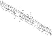
FIG. 3 is a schematic diagram of the front structure of the signal gram module of the present invention;
fig. 4 is a schematic diagram of the back structure of the letter-gram module of the present invention.
Detailed Description
To further clarify the objects, features and functions of the present invention, a preferred embodiment will be described in detail below with reference to the accompanying drawings, in which:
please refer to fig. 1, which is a schematic structural diagram of a preferred embodiment of the present invention, the present invention is a virtual line pressing structure of a needle plate of a flat knitting machine, mainly comprising a sinker 1, a tooth mouth piece 2 and a needle bed 3, wherein the tooth mouth piece 2 is located at an end of the needle bed 3, a fixed bottom plate 4 is arranged above the needle bed 3, a movable plate 5 is arranged above the bottom plate 4, the movable plate 5 is driven by a sinker assembly and pushes the sinker 1 to translate, after the sinker 1 translates to a certain position, the sinker 1 rotates to press a stitch, so that the front end of the sinker 1 is located above the tooth mouth piece 2 before pressing the stitch, thereby pressing the stitch or the long virtual line better, wherein, the rotation of the sinker 1 is also driven by the sinker assembly.
As shown in fig. 3 and 4, the letter-gram assembly comprises a letter-gram bottom plate 6, a letter-gram push plate 7 and a push row 8, wherein one side of the push row 8 is toothed and is linked with the motor through a screw rod. Push away row 8 and believe gram push pedal 7 and be connected and with the motor linkage, be equipped with at least a set of spout in the letter gram push pedal 7, still including being located 6 sides of letter gram bottom plate and corresponding at least two sets of activity triangles of a set of spout, the activity triangle comprises sinker triangle 11, the corresponding movable plate triangle 51 that promotes movable plate 5 that corresponds promotion sinker 1. Wherein, sinker triangle 11, activity piece triangle 51 are equipped with respectively and run through letter gram bottom plate 6 pulley holder 61, and all have the pulley to be located the spout that corresponds in the pulley holder 61, and when pushing away row 8 and promoting letter gram push pedal 7 horizontal migration, the shape of spout forces pulley holder 61 up-and-down motion, and accessible pulley drive sinker triangle 11 does not synchronous translational motion with activity piece triangle 51.
Specifically, the chute is composed of a first chute 71 and a second chute 72 which are sequentially arranged from top to bottom, and the left and right sides of the two chutes are provided with slopes to move upwards and then extend towards the two sides in a translation manner; wherein, the pulley corresponding to the sinker cam 11 is positioned in the first chute 71, and the pulley corresponding to the movable sinker cam 51 is positioned in the second chute 72. Namely, when the Xinke push plate 7 translates left and right, the movable triangle at the translation end performs opening motion, and the movable triangle at the other end performs resetting closing motion.
In order to ensure that the two processes are uniformly realized by the same set of movable triangles, the method comprises the following steps: when the two groups of movable cams are positioned in the middle of the sliding grooves, the distance between the pulley of the movable cam 51 and the slope of the second sliding groove 72 is shorter than the distance between the pulley of the sinker cam 11 and the slope of the first sliding groove 71, so that the movable cam 51 can be ensured to act in advance, the movable plate 5 pushes the sinker 1 to move forwards, and then the sinker cam 11 acts to rotate the sinker 1; the length of the upward slope of the first sliding groove 71 is greater than that of the second sliding groove 72, so that the pushing stroke of the sinker cam 41 is greater than that of the movable sinker cam 42, the sinker has a sufficient rotation angle, and the coil or the long dotted line is pressed.
The sensor 81 is fixedly connected to the push bar 8, and can sense the horizontal translation distance of the push bar 8 and the zero return state of the push bar 8, so that the opening or resetting process of the movable triangle is ensured to be complete.
As shown in fig. 2, the movable plate 5 has a groove, and the bottom of the sinker 1 rotates and moves in the groove, and in order to ensure smooth rotation of the sinker 1, the groove of the movable plate 5 is preferably a semicircular groove. When the knitting needle retreats from the ring, the movable plate cam 51 pushes the movable plate 5 to move forward, and after the movable plate 5 moves forward to the position, the sinker cam 11 drives the sinker 1 to rotate towards the tooth mouth piece 2 to press the coil.
A plurality of parallel inserting pieces 9 are uniformly distributed on the needle bed 3, and a bottom piece 4, a movable piece 5 and a sinker 1 are uniformly distributed in a gap between every two inserting pieces 9, because every inserting piece 9 and the bottom piece 4 need to be fixedly arranged, every inserting piece 9 and the bottom piece 4 are connected in series by steel wires, and every inserting piece 9 is fixed in a groove of the needle bed 3 side by side.
It should be understood that the above-described embodiments are merely exemplary of the present invention, and not restrictive, since various changes may be made therein without departing from the spirit and scope of the invention.
Claims (6)
1. The utility model provides a plain structure is pressed to flat loom faller, mainly includes sinker (1), tooth mouth piece (2) and needle bed (3), tooth mouth piece (2) are located needle bed (3) tip, its characterized in that: a fixed bottom plate (4) is arranged above the needle bed (3), a movable plate (5) is arranged above the bottom plate (4), the movable plate (5) is driven by a sinker component and pushes the sinker (1) to translate, the sinker component also drives the sinker (1) to rotate, the sinker component comprises a sinker bottom plate (6), a sinker push plate (7) and a push row (8), the push row (8) is connected with the sinker push plate (7) and is linked with a motor, at least one group of sliding grooves are arranged in the sinker push plate (7), at least two groups of movable triangles which are positioned on the side surface of the sinker bottom plate (6) and correspond to the group of sliding grooves are also included, the movable triangles comprise sinker triangles (11) corresponding to the sinker (1) and movable plate triangles (51) corresponding to the movable plate (5), the sliding grooves comprise a first sliding groove (71) and a second sliding groove (72) which are sequentially arranged from top to bottom, and the left side and the right side of each sliding groove are provided with a slope and then extend to two sides in a translation manner after the left side and right sides are both provided with slopes upwards; the pulley corresponding to the sinker cam (11) is positioned in the first sliding groove (71), the pulley corresponding to the movable sinker cam (51) is positioned in the second sliding groove (72), and the upward slope length of the first sliding groove (71) is greater than that of the second sliding groove (72); when two sets of movable triangles are positioned in the middle of the sliding grooves, the distance between the pulley of the movable plate triangle (51) and the slope of the second sliding groove (72) is shorter than the distance between the pulley of the sinker triangle (11) and the slope of the first sliding groove (71), an inductor (81) is fixedly connected to the push row (8), one side of the push row (8) is toothed, and the push row is linked with a motor through a screw rod.
2. The needle plate presser dotted structure of a flat knitting machine as claimed in claim 1, wherein: the sinker triangle (11) and the movable plate triangle (51) are respectively provided with a pulley seat (61) which penetrates through the sinker bottom plate (6), and pulleys are arranged in corresponding sliding grooves in the pulley seats (61).
3. A flat knitting machine needle plate presser virtual line structure according to claim 1 or 2, characterized in that: the movable plate (5) is provided with a groove, and the bottom of the sinker (1) rotates and moves in the groove.
4. A flat knitting machine needle plate presser virtual line structure according to claim 3, wherein: a plurality of parallel inserting sheets (9) are uniformly distributed on the needle bed (3), a bottom sheet (4), a movable sheet (5) and a settling sheet (1) are uniformly distributed in gaps among the inserting sheets (9), and the inserting sheets (9) and the bottom sheet (4) are connected in series by steel wires.
5. The needle plate presser dotted structure of a flat knitting machine as claimed in claim 4, wherein: the inserting pieces (9) are fixed in the grooves of the needle bed (3) side by side.
6. A flat knitting machine needle plate presser virtual line structure according to claim 5, characterized in that: the groove of the movable sheet (5) is a semicircular groove.
Priority Applications (1)
| Application Number | Priority Date | Filing Date | Title |
|---|---|---|---|
| CN201710875270.0A CN107400976B (en) | 2017-09-25 | 2017-09-25 | Virtual line structure is pressed to flat loom faller |
Applications Claiming Priority (1)
| Application Number | Priority Date | Filing Date | Title |
|---|---|---|---|
| CN201710875270.0A CN107400976B (en) | 2017-09-25 | 2017-09-25 | Virtual line structure is pressed to flat loom faller |
Publications (2)
| Publication Number | Publication Date |
|---|---|
| CN107400976A CN107400976A (en) | 2017-11-28 |
| CN107400976B true CN107400976B (en) | 2022-12-06 |
Family
ID=60388843
Family Applications (1)
| Application Number | Title | Priority Date | Filing Date |
|---|---|---|---|
| CN201710875270.0A Active CN107400976B (en) | 2017-09-25 | 2017-09-25 | Virtual line structure is pressed to flat loom faller |
Country Status (1)
| Country | Link |
|---|---|
| CN (1) | CN107400976B (en) |
Families Citing this family (4)
| Publication number | Priority date | Publication date | Assignee | Title |
|---|---|---|---|---|
| CN108589000B (en) * | 2018-03-21 | 2023-09-26 | 浙江丰帆数控机械有限公司 | Flat knitting machine |
| CN108360132B (en) * | 2018-04-25 | 2023-12-22 | 汕头市连兴实业有限公司 | Broken line pressing mechanism |
| WO2022210811A1 (en) * | 2021-03-29 | 2022-10-06 | 株式会社島精機製作所 | Movable sinker for weft knitting machines |
| CN114411320B (en) * | 2022-02-22 | 2023-07-18 | 宁波慈星股份有限公司 | Needle pushing triangle system suitable for stable needle connection |
Family Cites Families (9)
| Publication number | Priority date | Publication date | Assignee | Title |
|---|---|---|---|---|
| JP2618312B2 (en) * | 1992-07-09 | 1997-06-11 | 株式会社島精機製作所 | Sinker device in flat knitting machine |
| CN1284893C (en) * | 2004-03-23 | 2006-11-15 | 冯加林 | Control device for sinker |
| CN2887921Y (en) * | 2006-01-04 | 2007-04-11 | 江苏盛星实业有限公司 | Sinker mechanism of flat knitting machine |
| TW201311957A (en) * | 2011-09-14 | 2013-03-16 | Pai Lung Machinery Mill Co Ltd | Needle bed structure for flat knitting machines |
| CN202347228U (en) * | 2011-12-19 | 2012-07-25 | 松谷机械(惠州)有限公司 | Sinker cam capable of pressing center line |
| CN203080226U (en) * | 2013-03-14 | 2013-07-24 | 浙江丰帆数控机械有限公司 | Sinker device of flat knitting machine |
| CN203333944U (en) * | 2013-03-22 | 2013-12-11 | 章建伟 | Flat knitting machine sinker device |
| CN106894152B (en) * | 2017-03-31 | 2018-11-23 | 浙江丰帆数控机械有限公司 | A kind of flat machine |
| CN207276879U (en) * | 2017-09-25 | 2018-04-27 | 汕头市连兴实业有限公司 | A kind of horizontal loom needle plate pressure broken line construction |
-
2017
- 2017-09-25 CN CN201710875270.0A patent/CN107400976B/en active Active
Also Published As
| Publication number | Publication date |
|---|---|
| CN107400976A (en) | 2017-11-28 |
Similar Documents
| Publication | Publication Date | Title |
|---|---|---|
| CN107400976B (en) | Virtual line structure is pressed to flat loom faller | |
| KR20190111889A (en) | Horizontal knitting machine | |
| CN109853120B (en) | Sinker device of flat knitting machine head, flat knitting machine head and flat knitting machine | |
| CN1511205A (en) | Yarn guide of weft knitting machine | |
| CN201842949U (en) | Guide bar device for fall-plate warp knitting machine | |
| CN102182005B (en) | Yarn pressing plate moving mechanism of yarn-pressing type warp knitting machine | |
| CN106894152A (en) | A kind of flat machine | |
| CN101654839B (en) | Start-up bottom plate structure of computerized flat knitting machine | |
| CN206591230U (en) | A kind of flat machine | |
| KR20190116965A (en) | Knitting system used for horizontal knitting machines | |
| CN202090153U (en) | Fall plate motion mechanism of fall plate type warp-knitting machine | |
| CN212560626U (en) | Computerized flat knitting machine coil pressing device adopting electromagnetic needle selection | |
| CN102212933B (en) | Yarn pressing plate motion device for warp knitting machine | |
| CN219731230U (en) | Letter gram subassembly with two sets of movable triangle | |
| CN111519327B (en) | Sinker and sinker mechanism for flat knitting machine | |
| CN207276878U (en) | One kind pressure dotted line Kanehara component | |
| CN1256329A (en) | Slider for double-cylinder circular knitting machine | |
| CN202152400U (en) | Fall plate moving device for multi-bar warp knitting machine | |
| CN202152401U (en) | Yarn pressing plate moving device of warp knitting machine | |
| CN207276879U (en) | A kind of horizontal loom needle plate pressure broken line construction | |
| CN201512653U (en) | Bottom board raising structure of computer knitting flat knitting machine | |
| CN201245749Y (en) | Weaving start tension device of knitting horizontal machine | |
| CN215517856U (en) | Triangular bottom plate of three-system flat knitting machine | |
| CN108360132B (en) | Broken line pressing mechanism | |
| CN215800231U (en) | Knitting and yarn pressing mechanism of glove knitting machine |
Legal Events
| Date | Code | Title | Description |
|---|---|---|---|
| PB01 | Publication | ||
| PB01 | Publication | ||
| SE01 | Entry into force of request for substantive examination | ||
| SE01 | Entry into force of request for substantive examination | ||
| GR01 | Patent grant | ||
| GR01 | Patent grant |