CN107577832B - Machine system for optical end point control optimization and related methods - Google Patents
Machine system for optical end point control optimization and related methods Download PDFInfo
- Publication number
- CN107577832B CN107577832B CN201710484900.1A CN201710484900A CN107577832B CN 107577832 B CN107577832 B CN 107577832B CN 201710484900 A CN201710484900 A CN 201710484900A CN 107577832 B CN107577832 B CN 107577832B
- Authority
- CN
- China
- Prior art keywords
- machine
- retroreflector
- feed rate
- segment
- movement
- Prior art date
- Legal status (The legal status is an assumption and is not a legal conclusion. Google has not performed a legal analysis and makes no representation as to the accuracy of the status listed.)
- Active
Links
Images


Classifications
-
- G—PHYSICS
- G05—CONTROLLING; REGULATING
- G05B—CONTROL OR REGULATING SYSTEMS IN GENERAL; FUNCTIONAL ELEMENTS OF SUCH SYSTEMS; MONITORING OR TESTING ARRANGEMENTS FOR SUCH SYSTEMS OR ELEMENTS
- G05B19/00—Program-control systems
- G05B19/02—Program-control systems electric
- G05B19/04—Program control other than numerical control, i.e. in sequence controllers or logic controllers
- G05B19/042—Program control other than numerical control, i.e. in sequence controllers or logic controllers using digital processors
- G05B19/0428—Safety, monitoring
-
- G—PHYSICS
- G01—MEASURING; TESTING
- G01C—MEASURING DISTANCES, LEVELS OR BEARINGS; SURVEYING; NAVIGATION; GYROSCOPIC INSTRUMENTS; PHOTOGRAMMETRY OR VIDEOGRAMMETRY
- G01C15/00—Surveying instruments or accessories not provided for in groups G01C1/00 - G01C13/00
- G01C15/002—Active optical surveying means
-
- G—PHYSICS
- G01—MEASURING; TESTING
- G01S—RADIO DIRECTION-FINDING; RADIO NAVIGATION; DETERMINING DISTANCE OR VELOCITY BY USE OF RADIO WAVES; LOCATING OR PRESENCE-DETECTING BY USE OF THE REFLECTION OR RERADIATION OF RADIO WAVES; ANALOGOUS ARRANGEMENTS USING OTHER WAVES
- G01S17/00—Systems using the reflection or reradiation of electromagnetic waves other than radio waves, e.g. lidar systems
- G01S17/66—Tracking systems using electromagnetic waves other than radio waves
-
- G—PHYSICS
- G01—MEASURING; TESTING
- G01S—RADIO DIRECTION-FINDING; RADIO NAVIGATION; DETERMINING DISTANCE OR VELOCITY BY USE OF RADIO WAVES; LOCATING OR PRESENCE-DETECTING BY USE OF THE REFLECTION OR RERADIATION OF RADIO WAVES; ANALOGOUS ARRANGEMENTS USING OTHER WAVES
- G01S17/00—Systems using the reflection or reradiation of electromagnetic waves other than radio waves, e.g. lidar systems
- G01S17/88—Lidar systems specially adapted for specific applications
-
- G—PHYSICS
- G05—CONTROLLING; REGULATING
- G05B—CONTROL OR REGULATING SYSTEMS IN GENERAL; FUNCTIONAL ELEMENTS OF SUCH SYSTEMS; MONITORING OR TESTING ARRANGEMENTS FOR SUCH SYSTEMS OR ELEMENTS
- G05B15/00—Systems controlled by a computer
- G05B15/02—Systems controlled by a computer electric
-
- G—PHYSICS
- G05—CONTROLLING; REGULATING
- G05B—CONTROL OR REGULATING SYSTEMS IN GENERAL; FUNCTIONAL ELEMENTS OF SUCH SYSTEMS; MONITORING OR TESTING ARRANGEMENTS FOR SUCH SYSTEMS OR ELEMENTS
- G05B19/00—Program-control systems
- G05B19/02—Program-control systems electric
- G05B19/18—Numerical control [NC], i.e. automatically operating machines, in particular machine tools, e.g. in a manufacturing environment, so as to execute positioning, movement or co-ordinated operations by means of program data in numerical form
- G05B19/401—Numerical control [NC], i.e. automatically operating machines, in particular machine tools, e.g. in a manufacturing environment, so as to execute positioning, movement or co-ordinated operations by means of program data in numerical form characterised by control arrangements for measuring, e.g. calibration and initialisation, measuring workpiece for machining purposes
-
- G—PHYSICS
- G05—CONTROLLING; REGULATING
- G05B—CONTROL OR REGULATING SYSTEMS IN GENERAL; FUNCTIONAL ELEMENTS OF SUCH SYSTEMS; MONITORING OR TESTING ARRANGEMENTS FOR SUCH SYSTEMS OR ELEMENTS
- G05B19/00—Program-control systems
- G05B19/02—Program-control systems electric
- G05B19/18—Numerical control [NC], i.e. automatically operating machines, in particular machine tools, e.g. in a manufacturing environment, so as to execute positioning, movement or co-ordinated operations by means of program data in numerical form
- G05B19/402—Numerical control [NC], i.e. automatically operating machines, in particular machine tools, e.g. in a manufacturing environment, so as to execute positioning, movement or co-ordinated operations by means of program data in numerical form characterised by control arrangements for positioning, e.g. centring a tool relative to a hole in the workpiece, additional detection means to correct position
-
- G—PHYSICS
- G05—CONTROLLING; REGULATING
- G05B—CONTROL OR REGULATING SYSTEMS IN GENERAL; FUNCTIONAL ELEMENTS OF SUCH SYSTEMS; MONITORING OR TESTING ARRANGEMENTS FOR SUCH SYSTEMS OR ELEMENTS
- G05B19/00—Program-control systems
- G05B19/02—Program-control systems electric
- G05B19/18—Numerical control [NC], i.e. automatically operating machines, in particular machine tools, e.g. in a manufacturing environment, so as to execute positioning, movement or co-ordinated operations by means of program data in numerical form
- G05B19/404—Numerical control [NC], i.e. automatically operating machines, in particular machine tools, e.g. in a manufacturing environment, so as to execute positioning, movement or co-ordinated operations by means of program data in numerical form characterised by control arrangements for compensation, e.g. for backlash, overshoot, tool offset, tool wear, temperature, machine construction errors, load, inertia
-
- H—ELECTRICITY
- H02—GENERATION; CONVERSION OR DISTRIBUTION OF ELECTRIC POWER
- H02P—CONTROL OR REGULATION OF ELECTRIC MOTORS, ELECTRIC GENERATORS OR DYNAMO-ELECTRIC CONVERTERS; CONTROLLING TRANSFORMERS, REACTORS OR CHOKE COILS
- H02P6/00—Arrangements for controlling synchronous motors or other dynamo-electric motors using electronic commutation dependent on the rotor position; Electronic commutators therefor
- H02P6/14—Electronic commutators
- H02P6/16—Circuit arrangements for detecting position
- H02P6/17—Circuit arrangements for detecting position and for generating speed information
-
- G—PHYSICS
- G05—CONTROLLING; REGULATING
- G05B—CONTROL OR REGULATING SYSTEMS IN GENERAL; FUNCTIONAL ELEMENTS OF SUCH SYSTEMS; MONITORING OR TESTING ARRANGEMENTS FOR SUCH SYSTEMS OR ELEMENTS
- G05B2219/00—Program-control systems
- G05B2219/30—Nc systems
- G05B2219/36—Nc in input of data, input key till input tape
- G05B2219/36415—Adjust path and attitude tool by detecting path, line with a photosensor, laser
-
- G—PHYSICS
- G05—CONTROLLING; REGULATING
- G05B—CONTROL OR REGULATING SYSTEMS IN GENERAL; FUNCTIONAL ELEMENTS OF SUCH SYSTEMS; MONITORING OR TESTING ARRANGEMENTS FOR SUCH SYSTEMS OR ELEMENTS
- G05B2219/00—Program-control systems
- G05B2219/30—Nc systems
- G05B2219/37—Measurements
- G05B2219/37275—Laser, interferometer
-
- G—PHYSICS
- G05—CONTROLLING; REGULATING
- G05B—CONTROL OR REGULATING SYSTEMS IN GENERAL; FUNCTIONAL ELEMENTS OF SUCH SYSTEMS; MONITORING OR TESTING ARRANGEMENTS FOR SUCH SYSTEMS OR ELEMENTS
- G05B2219/00—Program-control systems
- G05B2219/30—Nc systems
- G05B2219/39—Robotics, robotics to robotics hand
- G05B2219/39033—Laser tracking of end effector, measure orientation of rotatable mirror
Landscapes
- Engineering & Computer Science (AREA)
- Physics & Mathematics (AREA)
- General Physics & Mathematics (AREA)
- Automation & Control Theory (AREA)
- Electromagnetism (AREA)
- Remote Sensing (AREA)
- Radar, Positioning & Navigation (AREA)
- Human Computer Interaction (AREA)
- Manufacturing & Machinery (AREA)
- Computer Networks & Wireless Communication (AREA)
- Power Engineering (AREA)
- General Engineering & Computer Science (AREA)
- Length Measuring Devices By Optical Means (AREA)
Abstract
The present invention provides a machine system with optical end point control and related methods for maintaining constant optical contact. In particular, the machine system comprises a machine that is movable in at least one direction. The machine is configured such that during the calibration phase, the steerable retroreflective system is mounted on the machine for movement therewith. The controller is configured to control movement of the machine in at least one direction. The machine system may be configured to automatically adjust the feed rate of the machine after determining that the speed required by the positioner to move the retroreflector to the desired location exceeds a certain segment feed rate threshold, such that the incident beam may remain in constant contact with the retroreflector throughout the movement of the machine from the first location to the second location.
Description
Technical Field
The invention relates to a machine system for optical end point control optimization and a related method.
Background
Current machining systems may use a laser tracking system in conjunction with a retroreflector (retroreflector) to accurately determine the position of a movable machine or component during a manufacturing or machining process that includes calibration. To avoid losing contact with the laser beam emitted by the laser tracking system during movement of the machine tool, improved retroreflectors and steerable retroreflector systems may be used to increase the acceptance angle of the retroreflector such that the retroreflector remains in constant contact with the laser beam. However, in some cases where movement of the mechanical tool causes the steerable retroreflection system and/or the laser tracking system to exceed the axial velocity of the respective system, the retroreflector may still lose contact with the laser beam. Existing solutions require the machine tool operator to manually observe the position and speed of the retroreflector and use feed trim on the machine tool controller to avoid laser beam interruption, increase labor requirements and extend machine tool measurement time due to errors in human-machine interaction. Accordingly, there is a need for an improved system and method to maintain optical contact between a retroreflective system and a light source during a manufacturing or processing process.
Disclosure of Invention
The following presents a simplified summary of the invention in order to provide a basic understanding of a particular embodiment of the invention. This summary is not an extensive overview of the invention and does not identify key or critical elements of the invention or delineate the scope of the invention. Its sole purpose is to present some concepts disclosed herein in a simplified form as a prelude to the more detailed description that is presented later.
Configured machine systems and methods for adjusting machine feed rates for optical endpoint control optimization are provided. The described systems and methods may be implemented to maintain constant optical contact between the light source and the installed steerable retroreflective system during manufacturing or processing processes that include calibration. In various embodiments, a machine system with optical end point control includes a machine capable of moving in at least one direction. The machine may be configured such that during the calibration phase, the steerable retroreflective system is mounted on the machine for movement therewith. The steerable retroreflective system may include a retroreflector for reflecting at least some light incident thereon and a positioner for moving the retroreflector. The positioner may comprise one or more of the following motors: azimuth motors and pitch (elevation) motors. The rotational axis of the azimuth motor is perpendicular to the rotational axis of the pitch motor.
The machine system may further include a controller configured to control movement of the machine in at least one direction. The machine may include one or more rotatable joints. The machine system may be configured to determine a position of the retroreflector based on a position determination of one or more axes of the machine, where each axis corresponds to a rotatable joint of the machine.
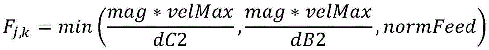
The machine system may be configured to adjust the feed rate of the machine after determining that the speed required by the positioner to move the retroreflector to the desired location exceeds a certain segment feed rate threshold, such that the incident beam may remain in constant contact with the retroreflector throughout the movement of the machine from the first location to the second location. In various embodiments, adjusting the feed rate of the machine includes adjusting the feed rate of the machine to be used for segments (F j,k ) The feed rate of the machine in (c) is limited to a value determined by the following equation:

where mag is the distance traveled by the machine from the start point to the end point of the segment, where velMax is the maximum rotational speed of one or more motors of the positioner, where dC2 is the degree of rotation of the azimuth motor required to adjust the retroreflector for the segment, where dB2 is the degree of rotation of the pitch motor required to adjust the retroreflector for the segment, and where norm feed is the maximum feed rate of the machine. The machine system may be further configured to adjust the feed rate of the machine by predetermining a feed rate path of the machine before the calibration phase occurs. Alternatively, and/or in addition, the machine system may be further configured to automatically adjust the feed rate of the machine in real time. In such embodiments, the machine system may be further configured to detect reflection of the light beam from the retroreflector and determine a location of a portion of the machine based on the reflected light.
A method for adjusting a machine feed rate is also provided. According to various embodiments, a method includes determining a first position and a second position of a machine. The first position and the second position may define movement of the machine in three dimensions. The machine may include one or more rotatable joints. The method further includes segmenting movement of the machine into one or more segments. Each segment defines an incremental movement of the machine between a start point and an end point in three-dimensional space.
The method further includes determining a location of a retroreflector mounted on the machine at a start point and an end point of each segment based on the location of the machine. Determining the position of the retroreflector may include detecting the position of one or more axes of the machine, where each axis corresponds to a rotatable joint of the machine.
The method further includes adjusting the feed rate of the machine after determining that the speed required by the positioner to move the retroreflector to the desired location exceeds a certain segment feed rate threshold, such that the incident beam may remain in constant contact with the retroreflector throughout the movement of the machine from the first location to the second location. In some embodiments, the positioner includes one or more of the following motors: azimuth motor and pitch motor. The rotational axis of the azimuth motor is perpendicular to the rotational axis of the pitch motor. In various embodiments, adjusting the feed rate of the machine includes adjusting the feed rate of the machine to be used for the segment (F j,k ) The feed rate of the machine in (c) is limited to a value determined by the following equation:
where mag is the distance traveled by the machine from the start point to the end point of the segment, where velMax is the maximum rotational speed of one or more motors of the positioner, where dC2 is the degree of rotation of the azimuth motor required to adjust the retroreflector for the segment, where dB2 is the degree of rotation of the pitch motor required to adjust the retroreflector for the segment, and where norm feed is the maximum feed rate of the machine. In some embodiments, adjusting the feed rate of the machine includes predetermining a feed rate path of the machine before the calibration process occurs. Alternatively, and/or in addition, adjusting the feed rate of the machine occurs automatically in real-time. In such embodiments, the method may further include detecting reflection of the light beam from the retroreflector and determining a location of a portion of the machine based on the reflected light.
Other embodiments of the invention include corresponding devices, systems, and computer programs configured to perform the actions of the methods described herein. For example, a non-transitory computer readable medium is provided that includes one or more programs configured for execution by a computer system. In some embodiments, one or more programs include instructions for performing the actions of the described methods and systems. These other embodiments may each optionally include one or more of the following features. These and other embodiments are further described below with reference to the drawings.
Drawings
Fig. 1 is a schematic representation of a machine system including a plurality of steerable retroreflective systems according to some embodiments.
Fig. 2 is a schematic illustration of a steerable retroreflective system in accordance with some embodiments.
Fig. 3A is a schematic illustration of a machine system including a steerable retroreflective system mounted to a machine, according to some embodiments.
Fig. 3B is a schematic illustration of a machine system including an installed steerable retroreflective system illuminated by a light source, in accordance with some embodiments.
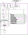
FIG. 4 is a schematic representation of a machine system of one embodiment of the present invention indicating the interrelationship between various components and signals passing therethrough.
Fig. 5A-5B illustrate process flow diagrams corresponding to methods for adjusting a machine feed rate, in accordance with some embodiments.
FIG. 6 is a block diagram illustrating an example of a computer system capable of implementing the various processes described in this disclosure.
Fig. 7 is a schematic illustration of an aircraft according to some embodiments.
FIG. 8 is a block diagram of an aircraft manufacturing and service method that may utilize the methods and assemblies described herein.
Detailed Description
In the following description, numerous specific details are set forth in order to provide a thorough understanding of the presented concepts. The presented concepts may be practiced without some or all of these specific details. In other instances, well known process operations have not been described in detail in order not to unnecessarily obscure the described concepts. While some concepts will be described in connection with specific embodiments, it should be understood that these embodiments are not intended to be limiting. On the contrary, the invention is intended to cover alternatives, modifications and equivalents, which may be included within the spirit and scope of the invention as defined by the appended claims.
For example, the techniques of the present invention will be described in the context of a particular machine system (e.g., a system for aircraft manufacturing or tooling). However, it should be noted that the techniques and mechanisms of the present invention are applicable to a variety of other position-tracking systems. The term "retroreflective system" as used herein may be used synonymously with "active tracker". In the following description, numerous specific details are set forth in order to provide a thorough understanding of the present invention. Particular example embodiments of the invention may be practiced without some or all of these specific details. In other instances, well known process operations have not been described in detail in order not to unnecessarily obscure the present invention. For clarity, various techniques and mechanisms of the present invention are sometimes described in the singular. However, it should be noted that, unless otherwise indicated, some embodiments include multiple iterations of a technique or multiple instances of a mechanism.
For clarity, various techniques and mechanisms of the present invention are sometimes described in the singular. However, it should be noted that, unless otherwise indicated, some embodiments include multiple iterations of a technique or multiple instances of a mechanism. For example, the system uses the processor in various environments. However, it will be appreciated that a system may use multiple processors, unless otherwise indicated, while remaining within the scope of the present invention. Furthermore, the techniques and mechanisms of the present invention sometimes describe a connection between two entities. It should be noted that a connection between two entities does not necessarily represent a direct unimpeded connection, as a number of other entities may reside between the two entities. For example, a processor may be connected to a memory, but it should be understood that various bridges and controllers may reside between the processor and the memory. Thus, unless otherwise indicated, a connection does not necessarily represent a direct unimpeded connection.
SUMMARY
The present invention describes a novel machine system with improved retroreflective system and laser tracking technology. In particular, the machine system may include a machine that is movable in at least one direction and a steerable retroreflective system mounted on the machine so as to move therewith during a calibration phase. The machine system is capable of determining the location of the machine and the retroreflective system based on programmed machine instructions. The machine system may implement a pre-process to determine an optimal feed rate to adjust the machine movement to ensure that the retroreflective system is able to make appropriate adjustments during the calibration phase to maintain constant contact with at least one light ray in the light beam generated from the light source. This pre-treatment may be performed prior to each machining process to improve performance and accuracy during the calibration phase. In some embodiments, the calibration phase occurs before the machine is implemented in any machining and/or tooling process. Alternatively, and/or in addition, the machine system may automatically monitor and adjust the speed of machine movement in real-time during machining and/or tooling processes by illuminating the retroreflective system and receiving reflections therefrom. The process controller may implement various algorithmic functions and calculations, including inverse kinematics of retroreflector and laser tracker axis positions and machine tool kinematics, to calculate an accurate machine tool feed rate to maximize measurement throughput and prevent loss of contact with the light source.
The improved system has a number of advantages over conventional laser tracking systems. For example, the disclosed machine system may segment programmed machine movements and predict movement requirements of a retro-reflective system to maintain optical contact with a light source and thereby reduce or increase the speed of a robot arm endpoint to which the retro-reflective system is coupled. This eliminates the need for a machine tool operator to manually observe the position and speed of the retroreflective system and manually adjust the feed rate through a feed trim on the machine tool controller. Those skilled in the art will recognize that line of sight interruption when calibrating a machine and/or machining complex structures will require a significant amount of time to recalibrate and reduce the productivity of the machining process. Furthermore, eliminating the need for a machine tool operator reduces errors due to human interaction, reduces labor requirements, and shortens machine tool measurement times. Finally, adjustment of the mechanical tool feed rate in combination with improved retroreflective structure and retroreflective system mobility is used as an additional mechanism to ensure optical contact between the retroreflective system and the light source. In general, the improved systems and methods may result in faster machining times and more accurate machine tool measurements.
Example embodiment
To better understand the various aspects of the installed retroreflector system, a brief description of a machine system with installed retroreflectors is presented. Fig. 1 is a schematic representation of a machine system including a plurality of steerable retroreflective systems 200, according to some embodiments. As shown somewhat generally in fig. 1, the machine system 100 includes a machine 120, such as a robotic arm, a machine tool, or other mechanical positioning device. For example, the machine may be a Computer Numerical Control (CNC) device, such as a robotic drill, or the like. However, for purposes of illustration, the machine is relatively generally depicted and is capable of movement in multiple directions and about multiple axes, i.e., the machine has multiple degrees of freedom. Although not necessary to practice the invention, the machine includes an end effector 140, such as a drill bit or the like, for holding (hold) tools. While the steerable retroreflective system 200 of the present invention can be used in connection with a variety of machines, one embodiment of a machine system 100 that can be used with the steerable retroreflective system is a SOMaC system as described by U.S. patent No. 5,903,459, the contents of which are incorporated herein.
In various embodiments, as described further below and with reference to fig. 2, the retroreflective system 200 may include a retroreflector for reflecting light from a light source. In other embodiments, machine system 100 may include one or more steerable retroreflective systems 200 mounted on respective portions of machine 120. For example, steerable retroreflective system 200 can be mounted on opposite sides of end effector 140 of machine 120 to ensure that at least one retroreflector is always within view. In other embodiments, steerable retroreflective system 200 can be mounted on other portions of machine 120 or on workpiece or component 130 without departing from the spirit and scope of the invention.
In some embodiments, the machine system 100 may also include a laser measurement system (LAS) 180, i.e., a laser tracker, that operates as a light source for illuminating the steerable retro-reflective system 200. In some embodiments, the machine system 100 may include two or more laser trackers. The real-time three-dimensional laser measurement system 180 is a state of the art measurement system that can obtain large amounts of accurate three-dimensional data in a rapid manner. This laser measurement system 180 may typically include an absolute ranging capability and a motorized angle manipulation head for manipulating the laser beam. The laser measurement system 180 may also contain a feedback system that controls manipulation by continually driving the laser beam to follow or track the retroreflector. As shown in fig. 1, a laser beam 190 emitted by a laser measurement system 180 is directed from a laser tracker head toward a steerable retro-reflective system 200 mounted on an end effector 140 of machine 120. In some embodiments, by measuring the return beam, the laser tracker head of the laser measurement system 180 can determine the distance and direction (i.e., horizontal and vertical angles and ranges) to the retroreflector during various machining processes that include a calibration phase. These three measurements, i.e. the range, horizontal and vertical angles, can establish a spherical coordinate system, which can be easily converted into a cartesian coordinate system. In some embodiments, various commercially available or custom laser trackers may be employed.
During machining operations that include a calibration stage, in some embodiments, the component 130 is typically held in a fixed position, as shown in fig. 1. Machine 120 may then be positioned proximate to component 130 such that tools carried by end effector 140 may contact and machine component 130 as desired. To accurately determine the position of the end effector 140, the laser measurement system 180 may illuminate the end effector, and in particular, the steerable retro-reflective system 200 carried by the end effector 140. It will be appreciated that the machine will frequently reposition the end effector during machining that includes calibration. In a conventional machine system 100 that includes a retroreflector mounted on an end effector 140, the end effector 140 is often moved such that the laser beam 190 will no longer be within the acceptance angle defined by the retroreflector. In some embodiments, the component 130 is not included during the calibration phase. During the calibration phase, the accuracy and/or consistency of machine movements by machine 120 implementing machine instructions may be measured using laser measurement system 180 and steerable retroreflection system 200.
In accordance with the present invention, steerable retroreflective system 200 can include one or more motors to steer the retroreflector through a wide range of angles, thereby providing a significantly larger effective acceptance angle than conventional retroreflectors. For example, steerable retroreflective system 200 may have an acceptance angle that exceeds 320 °. Thus, the area outside the acceptance angle is a cone towards an angle (subtend) of less than 40 °.
Thus, the steerable retroreflection system can continuously receive the laser beam 190 emitted by the laser measurement system 180 even as the end effector 140 is moved to various positions. Thus, the machine system 100 of fig. 1 can determine and/or confirm the position of the retroreflector, and in turn, the end effector 140 in nearly all positions that the end effector 140 will assume. However, as previously described, moving the machine 120 to a different axis position may still cause the laser beam 190 to exceed the acceptance angle of the steerable retroreflective system 200, where the feed rate of the machine 120 exceeds the axis speed of the axis of rotation of the retroreflective system 200 and/or laser measuring system 180.
Fig. 2 is a schematic illustration of a steerable retroreflective system 200, such as previously described in fig. 1, in accordance with some embodiments. In various embodiments, steerable retroreflective system 200 includes a retroreflector 202 for reflecting some of the light incident thereon. For example, reference is made to the steerable retroreflective system described in U.S. patent 6,392,222 entitled "MACHINE SYSTEM HAVING OPTICAL ENDPOINT CONTROL AND ASSOCIATED METHOD (machine system with optical end point control and related methods)", the contents of which are also incorporated herein. In some embodiments, the retroreflector 202 comprises a triangular prism having an input surface through which incident light is received and a plurality of reflective surfaces for reflecting the incident light. It is known to those skilled in the art that reflective surfaces are typically mirrored to facilitate reflection of incident light. However, the retroreflector 202 may be designed to allow a portion of the incident light to leave the retroreflector 202 without being reflected thereby. For example, a triangular prism may define a window opposite the input surface such that a plurality of reflective surfaces converge at the window. The window is at least partially transmissive such that light incident on the window passes through the window and exits the triangular prism. In order to allow light to escape through the window, the window preferably does not have any mirrored coating.
For a window of a given transmissivity, the percentage of incident light allowed to escape through the window is defined by the size of the window relative to the input surface of the triangular prism. For example, the window may be sized such that between about 0.5% and 5% of the light received through the input surface of the triangular prism passes through the window. In some embodiments, the window is sized such that about 1% of the light received through the input surface of the triangular prism passes through the window. In various embodiments, the retroreflector 202 may be configured to allow a predetermined percentage of incident light to leak through the window in various ways. For example, the apex of the triangular prism may be truncated or removed. For example, reference is made to the triangular prism structure described in us patent 6,392,222.
Various other types of retroreflectors may be used in other embodiments of the retroreflective system 200. Another type of retroreflector is a hollow pyramid retroreflector composed of three mutually orthogonal mirrors. Although the lateral displacement between the incident and reflected beams does not change with angle of incidence, hollow cube-corner retroreflectors are generally relatively difficult to manufacture and therefore more expensive than comparable triangular prism reflectors. In addition, hollow pyramid retroreflectors typically have an acceptance angle of +/-25 °. A third type of retroreflector is a cat eye, in which several hemispherical lenses are combined to form a single optical element. Although the cat eye has a large acceptance angle, e.g., about +/-60 °, the cat eye is much more expensive than a triangular prism retroreflector or a hollow cube-corner retroreflector. Although the cat eye has a much larger acceptance angle than a triangular prism retroreflector or a hollow pyramid retroreflector, the acceptance angle of the cat eye is still insufficient in many cases, particularly during many high precision manufacturing operations where the retroreflector will be mounted on an end effector of a robot or other machine tool that will take many different positions during the manufacturing process.
In some embodiments, steerable retroreflective system 200 may also include an optical detector, e.g., a photocell, for detecting light leakage through retroreflector 202. In some embodiments, this optical detector detects the relative position of the light leakage so that the angle of incidence α can be determined. Steerable retroreflective system 200 also includes a controller, such as a process controller 402 (described further below in connection with fig. 4), such as a microprocessor or the like, for receiving signals from the optical detector and for determining the angle of incidence. In this regard, the controller 402 may be represented by the following equation: α=tan-1 (D/D) determines the incident angle α, where D is the predetermined separation distance between the optical detector and the virtual apex 211 of the retroreflector, and D is the offset of the light leakage through the retroreflector 202 from the center or other reference location defined by the optical detector. In some embodiments, the retroreflective system 200 and associated locator and/or motor may be controlled by a retroreflective system controller separate from the controller 402. In some embodiments, controller 402 may send commands to this retroreflective system controller and receive status information of the retroreflective system from this retroreflective system controller.
In some embodiments, the retroreflector 202 and the optical detector are typically mounted within a housing, such as the retroreflector housing 202'. The housing 202' is in turn mounted to an object to be monitored, such as an end effector 140 of a machine (e.g., machine 120 or workpiece 130) for movement therewith. However, in other embodiments, the retroreflector 202 may also be controllably positioned relative to the object to be monitored. In this regard, steerable retroreflective system 200 includes means for controllably steering retroreflector 202 in response to light leakage detected by the optical detector. In some embodiments, the means for controllably manipulating the retroreflector includes at least one positioner for moving the retroreflector and a retroreflector system controller, such as the microprocessor described above, that directs the at least one positioner to controllably manipulate the retroreflector 202 in response to light leakage detected by the optical detector.
In various embodiments, the positioner may include one or more motors for moving the retroreflector 202 about the respective axes. For example, the means for controllably maneuvering the retroreflector 202 may include a pitch motor 204. In some embodiments, pitch motor 204 may be a stepper motor having a shaft connected to retroreflector housing 202' in which retroreflector 202 and the optical detector are disposed. Thus, the retroreflector system controller may actuate the pitch motor 204 to rotate the shaft and, in turn, the retroreflector 202 about the pitch axis 204'. Additionally, the means for controllably maneuvering retroreflector 202 may include azimuth motor 206. Similarly, the azimuth motor may be a stepper motor having a shaft connected to the housing 202'. Thus, the retro-reflective system controller may actuate the azimuth motor 206 to rotate the shaft and thereby rotate the reflector housing 202' containing the retro-reflector 202 and the optical detector. Specifically, azimuth motor 206 rotates retroreflector 202 about azimuth axis 206' defined by the axis of azimuth motor 206. In other embodiments, pitch motor 204 and/or azimuth motor 206 may include various other motor types, e.g., a DC motor, a servo motor, etc.
In some embodiments, axes 204 'and 206' defined by the shafts of the pitch motor and azimuth motor, respectively, intersect at the apex 211 of the retroreflector 202, such that the apex 211 of the retroreflector 202 remains in the same position, and the remainder of the retroreflector pivots about the pitch motor 204 and/or azimuth motor 206 after actuation thereof. As further depicted in fig. 2, the azimuth motor may be mounted to a motor mount 210, which in turn is fixed to an object to be monitored, such as end effector 140 of machines 120, 120a, and 120B schematically shown in fig. 1 and 3A-3B. Thus, controlled actuation of the pitch motor and azimuth motor may controllably steer the retroreflector relative to the object to which steerable retroreflector system 200 is mounted. In some embodiments, the retro-reflective system controller is preferably in electrical communication with each of the pitch motor 204 and the azimuth stepper motor 206 to controllably actuate the motors. In other embodiments, steerable retroreflective system 200 can include other means for controllably steering retroreflector 202 without departing from the spirit and scope of the invention.
The retroreflector 202 may be manipulated by an operator of the machine system 100 in any desired manner, as described below. For example, the retroreflector may be maneuvered in an open loop manner through a series of positions, each of which is defined in advance. Alternatively, the retroreflector may be manipulated in a closed loop manner by the retroreflector system controller to follow or track the incident light. In this regard, steerable retroreflective system 200 may track incident light in a variety of ways. In some embodiments, for example, the optical detector may define a target area, and the retroreflector 202 is manipulated by the retroreflector system controller to maintain the light leakage within the target area. The retroreflector 202 may also be manipulated by the retroreflector controller to follow the incident light by keeping the light leakage within the target area.
Examples of machine systems
The following diagram provides additional examples of machine systems, such as machine system 100 previously described in connection with fig. 1. Fig. 3A is a schematic illustration of a machine system 300 including a steerable retroreflective system mounted to a machine, according to some embodiments. In various embodiments, machine system 300 includes steerable retroreflective system 200 mounted to end effector 140a of machine 120 a. In some embodiments, end effector 140a may be end effector 140 and machine 120a may be machine 120. As depicted in fig. 3A, machine 120a is configured as a robotic arm mounted to a fixed motor mount 310a and includes one or more rotatable joints, including joints 308a, 308b, and 308c, that allow robotic arm 120a (e.g., machine 120) to move in multiple directions and about multiple axes. Fig. 3B is a schematic illustration of a machine system 301 including an installed steerable retroreflective system illuminated by a light source, in accordance with some embodiments. In various embodiments, the system 301 includes a steerable retroreflective system 200 mounted to an end effector 140b of the machine 120 b. In some embodiments, end effector 140b may be end effector 140 and machine 120b may be machine 120. As depicted in fig. 3B, machine 120B is configured with one or more rotatable joints, including joints 308d and 308e, that allow machine 120B (e.g., machine 120) to move in multiple directions and about multiple axes. In addition, the machine system 301 may include a laser measurement system 180b that irradiates the retroreflector of the steerable retroreflector system 200 with the laser beam 190 b. The laser measurement system 180b may be the laser measurement system 180 previously described in connection with fig. 1. In some embodiments, the laser measurement system 180b may include a pitch motor 182 and an azimuth motor 184 for movement in multiple directions and about multiple axes.
FIG. 4 is a schematic representation of a machine system 400 of one embodiment of the present invention indicating the interrelationship between components and signals passing through the components. The dashed lines in fig. 4 indicate optional operations and/or components for system 400. In some embodiments, machine system 400 may be implemented as machine system 100 previously described in connection with fig. 1, and/or machine systems 300 and/or 301 previously described in connection with fig. 3A-3B. In some embodiments, the machine system 400 is implemented during a calibration phase of a machining and/or tooling process. In some embodiments, the components shown in fig. 4 may be connected by wireless and/or wired networks. In some embodiments, the machine system 400 may also include one or more laser measurement systems, such as a laser tracker 180, each of which includes, among other components, a laser measurement system controller 180' that manipulates the laser beam 190 via drive motors 182 and 184 or other motorized angle manipulation heads. Thus, the process controller 402 may provide commands to the laser measurement system controller 180' to specify the direction in which the laser beam is to be steered. Based on the signals reflected from the respective retroreflectors 202, the laser measurement system controller 180' may determine the actual location of the retroreflectors 202, and in turn, the actual location of the portion or component 130 of the machine 120 in which the retroreflectors 202 are mounted.
As shown in fig. 4, the laser measurement system controller may then transmit a signal to the process controller 402 indicating the actual position of the retroreflector 202. Based on the signal indicative of the actual position of the retroreflector 202, and thus the actual position of the portion or component 130 of the machine 120 in which the retroreflector 202 is installed, the process controller 402 may modify commands transmitted to the machine controller 404 that direct the movement of the corresponding machine in order to compensate for differences between the actual position of the machine 120 and the predicted position of the machine 120 that are considered by the CNC program during the machining process that includes the calibration phase. By compensating for differences between the actual position of machine 120 and the expected position of machine 120 (machine systems, e.g., systems 100, 300, and/or 301), the present invention may more accurately machine components than conventional machine systems. In this regard, changes occurring to component 130 and/or machine 120 (e.g., due to temperature fluctuations) may be accommodated, for example, by modifying commands transmitted from process controller 402 to machine controller 404 that direct movement of the respective machine (e.g., machine 120, 120a, and/or 120 b).
In some embodiments, a single process controller 402 may be in direct communication with steerable retroreflection system 200, machine 120, and laser measurement system 180, or any combination thereof. However, as shown in fig. 4, the system 400 may not include the steerable retroreflection system 200 and/or the laser measurement system controller 180' in various embodiments. As previously described, steerable retroreflective system 200 may be controlled by a separate retroreflective system controller (not shown) that may or may not be in communication with process controller 402. Similarly, the laser measurement system 180 and the laser measurement system controller 180' may comprise separate systems that may or may not communicate with the process controller 402. For example, the process controller 402 and the machine controller 404 include separate systems that do not communicate with the laser measurement system controller 180' and/or the steerable retroreflection system 200, as well as the corresponding retroreflection system controllers. In practice, the data generated from each system can be analyzed and applied offline to establish CNC final path commands.
The machine system 100 of the present disclosure may be used in a variety of applications. For example, a machine system may be used with a single steerable retroreflector system 200 and a single laser measurement system 180 mounted to machine 120 to measure the XYZ position of a retroreflector (e.g., retroreflector 202) according to a static mode or a dynamic mode. In the static mode, the machine system of the present disclosure may measure the position of the retroreflector 202, and in turn, the position of the portion of the machine 120 where the retroreflector 202 is mounted. In the dynamic mode, the machine system 400 repeatedly measures the position of the retroreflector 202, and thus the position of the portion of the machine 120 where the retroreflector 202 is mounted, in order to effectively monitor the path followed by the machine's movement. In this embodiment where the machine system 400 includes a single steerable retroreflective system 200 and a single laser measurement system 180, the steerable retroreflective target will typically operate in a closed loop mode in order to track the laser beam emitted by the laser measurement system 180. Thus, the machine 120 may move over a greater distance and may take on more orientations while continuing to receive the laser beam emitted by the laser measurement system 180 within the acceptance angle defined by the retroreflector 202.
In other embodiments, machine system 100 may include a single laser measurement system 180 and multiple steerable retroreflective targets 200 mounted on different portions of machine 120. To illuminate each of these steerable retroreflector systems, the laser measurement system is preferably driven by the process controller 402 to sequentially illuminate the respective retroreflector 202, each of which is steered toward the laser measurement system in the manner described above. By measuring the relative positions of the multiple retroreflectors, the machine system of this embodiment can advantageously determine the XYZ location of the machine as well as the pitch, yaw, and roll of the machine in a static mode (i.e., in a specific location) or in a dynamic mode as the machine moves along the travel path.
Instead, the machine system 100 may include multiple laser measurement systems 180 and a single steerable retroreflective system 200 mounted on the machine 120. In this regard, the process controller 402 preferably commands the steerable retroreflection system 200 to sequentially point to at least one of the plurality of laser measurement systems 180 and track a different one of the plurality of laser measurement systems 180. Thus, the steerable retrorefiective system 200 may operate in a closed loop manner to track a particular laser measurement system until commanded to point to another laser measurement system 180 by the process controller 402, at which point the steerable retrorefiective system 200 begins operating in an open loop manner to move toward the other laser measurement system. After the steerable retroreflection system 200 is directed toward the other laser measurement system 180, the steerable retroreflection system 200 may again operate in a closed loop mode in order to track the other laser measurement system 180. Thus, the machine system of this embodiment may also measure XYZ positions of the machine 120 and statically or dynamically measure pitch, yaw, and roll of the machine 120.
Further, the machine system 100 may include both a plurality of laser measurement systems 180 and a plurality of steerable retroreflective systems 200. While the machine system of this embodiment may be configured in a variety of ways, the machine system may be configured such that each laser measurement system 180 is assigned to illuminate a particular steerable retroreflector system 200 in order to reduce the time required to measure the locations of the multiple retroreflectors 202. Alternatively, the machine system 100 may direct each laser measurement system 180 to identify the easiest to reach retroreflector 202 and measure the location of the retroreflector. In any event, the machine system of this embodiment may measure the XYZ position of machine 120 in real time or near real time and measure the pitch, yaw, and roll of machine 120 statically or dynamically.
Adjusting machine movement feed rate to maintain constant light beam incident on retroreflectors
Although manipulating retroreflector 202 by controller 402 to track incident light may increase the effective acceptance angle of retroreflector system 200, the axis speed of the axis of rotation of retroreflector system 200 and/or laser measurement system 180 may still be exceeded when machine 120 is moved to a different axis location and/or three-dimensional point in space. This problem may occur particularly when the axes of rotation 204 'and 206' of the retroreflector 202 pass through the singular point (singularity point). For example, the rotation axes 204' and 206' may reach a singular point where the vector introduced to the laser beam 190 is collinear with the centerline of the azimuth rotation axis 206 '. In this position, very small changes in the movement of the machine 120 may produce the large changes required for the rotation of the retroreflector 202 through the azimuth axis of rotation 206' to maintain optical contact with the laser beam 190. By dividing the movement of the machine 120 and limiting the feed rate or the speed of the end effector movement for discrete segments, the feed rate of the machine 120 may be limited to match the rotational alignment capability limitations of the retroreflective system 200 and/or the laser measurement system 180.
In some embodiments, the process controller 402 may implement preprocessing to segment machine instructions for movement of the machine 120 prior to a machining process that includes a calibration phase. For example, machine instructions may include 200 lines of instructions for moving machine 120 into various machine positions. Such instructions may further include instructions for splitting movement of machine 120 from one machine location to another machine location. The more the segmentation is defined, the more accurate the prediction of the rotational axis speed of the retroreflective system 200 that is required to maintain optical contact between the retroreflector 202 and the laser management system 180, and the more accurate the limit feed rate that can be calculated for the machine system 100.
In various embodiments, the machine axis position P may include points X, Y, Z, C and/or a, where each point represents the position of the axis of the rotatable joint of the machine 120 such that:
P=[XYZ] T
in some embodiments, variables C and a refer to the rotational axis of a machine system controlling an end effector, e.g., end effector 140b in system 301. C refers to the azimuth angle and a refers to the pitch angle of the end effector 140 b. Similarly, the axis position P of the retroreflective system 200 AT Point C2, which corresponds to the position of azimuth axis 206', and point B2, which corresponds to the position of pitch axis 204', may be included such that:
P AT =[C2B2] T
Finally, the location PL of the laser measurement system 180 may include point X L 、Y L And Z L Such that:
P L =[X L Y L Z L ] T
with forward motion conversion, a specific position of machine 120 and a specific position of a machine tool at end effector 140 may be determined based on specified values of joint parameters. For example, about axis A R x (θ A ) And C axis R Z (θ C ) The machine coordinates of machine 120 may be:


machine coordinate T Z The translation matrix of (X, Y, Z) may be:

the location of the retroreflector 202 may be further determined by the a-axis pivot length pivotLength and the length targetLength of the retroreflective system 200, where L = pivotLength + targetLength. Thus, the length T for the A-axis pivot length and the retroreflective system 200 L The translation matrix of (L) may be:

by defining such variables, the forward motion transformation matrix FK can be determined by the following equation:
FK=T Z (x,y,z)*R Z (θ c )*R x (θ A )*T L (x,y,z)
using the forward motion matrix FK, the tool tip coordinate p is determined as:


the tool axis vector (i, j, k) may be determined as:


subsequently, the orientation of the axis of the retroreflective system 200 in the 3-dimensional space is determined by using inverse kinematics. For example, a vector from the retroreflector to the location of the laser measurement system 180 may be found by:


the magnitude of v is then scaled to obtain a unit vector with an inverted sign:
v=-v/|v|
The rotational coordinates (in degrees) of the retroreflective system 200 can then be calculated by the following equation:
C2=atan2(j T ,i T )*180/π


for each machine position P j ,


S=ceil(mag j /D)-1
Given N as the number of machine positions, j describes the index j=1..n of machine positions. Wherein D is asEach segment is a desired distance between positions j and j+i, and given S as the number of segments between positions j and j+i, k is an index of the segment between each position j and j+1, where k=1..s, and mag j Is the linear distance traveled by machine 120 from the first position to the second position.
Subsequently, for each segment P j,k ,


Here, mag j,k Is the linear distance traveled by machine 120 from the start point to the end point of a given segment. Given the maximum rotational speed velMax of the motor of the retroreflective system 200 and the feed rate threshold norm feed of the machine 120, a value (F) can be determined using the following equation j,k ) To limit the feed rate of the machine 120 or the speed of the end effector in order to optimize the machine feed rate to maintain optical contact between the retroreflector 202 and the laser management system 180.

Where dC2 is the rotation of the azimuth motor required to adjust the retroreflector for the segment, and where dB2 is the rotation of the pitch motor required to adjust the retroreflector for the segment. Thus, (mag) j,k * velMax)/dC 2 represents the maximum rate of movement of machine 120 that azimuth motor 206 can use to optimally move the retroreflector from the beginning of the segment to achieve the desired location at the end of the segment. Similarly, (mag) j,k * velMax)/dB 2 represents the maximum rate of movement of machine 120, pitch motor 204The retroreflector may be optimally moved from the start of the segment at the maximum rate to achieve the desired location at the end of the segment. In some embodiments, mag j,k Is in units of distance, e.g., inches. In some embodiments, the units of velMax are degrees over time, e.g., degrees/min. In some embodiments, units of dC2 and dB2 are degrees. In some embodiments, the units of norm feed are distance/time, e.g., inches/minute.
Using this algorithm and the associated calculations, the process controller 402 may send segments (F j,k ) The feed rate of the machine 120 in (a) is limited to (mag j,k *velMax)/dC2、(mag j,k * The minimum between velMax)/dB 2 and norm feed determines the maximum feed rate of the machine 120 based on the rotational speed constraints of the retroreflective system 200. For example, a typical number of feed rate threshold norm feed for a machine (e.g., machine 120) may be about 300 inches/minute. The maximum rate at which azimuth motor 206 can optimally move retroreflector 202 from the starting point of the first segment to achieve the desired location at the ending point of the first segment can be 400 inches/minute, and the maximum rate at which pitch motor 204 can optimally move retroreflector 202 from the starting point of the first segment to achieve the desired location at the ending point of the first segment is 450 inches/minute. Here, the process controller 402 need not limit the feed rate of the machine 120 below a feed rate threshold norm feed, which is 300 inches/minute.
However, if the azimuth motor 206 and/or the elevation motor 204 can optimally move the retroreflector 202 from the start of a segment to achieve a maximum rate of less than 300 inches/minute for the desired location at the end of the segment, the process controller 402 can adjust the feed rate of the machine 120 accordingly for that particular segment. For example, the maximum rate at which the azimuth motor 206 can optimally move the retroreflector 202 from the beginning of the second segment to achieve the desired location at the end of the second segment can be 250 inches/minute. Here, the process controller 402 may issue positioning commands to the machine controller 404 (as depicted in fig. 4) to slow the feed rate of the machine 120 to 250 inches/minute in order to ensure constant contact between the retroreflector 202 and the laser beam 190 emitted from the laser management system 180. If the maximum rate of optimal movement of retroreflector 202 by azimuth motor 206 and/or elevation motor 204 increases beyond the norm feed value at the subsequent segment, process controller 402 may then increase the feed rate of machine 120 to a feed rate threshold norm feed for the subsequent segment.
This process for segmenting machine movement and adjusting machine feed rate is more advantageous for existing solutions that require a machine tool operator to manually observe the position and speed of the retroreflective system 200 and use feed trimming on the machine tool controller 404 to avoid laser beam interruption. The existing system generates errors due to man-machine interaction, increases labor requirements and prolongs machine tool measurement time. In some embodiments, the measurement time may be reduced by about 50% during the measurement without the need for a machine tool operator.
In other embodiments, the process controller 402 may use similar inverse kinematics and mechanical tool kinematics to calculate that the azimuth motor 184 and/or the pitch motor 182 of the laser measurement system 180b may optimally adjust the laser beam 190b from the start of a segment to achieve the lowest maximum rate of desired position at the end of the segment. Thus, the process controller 402 may be segment specific j,k ) Limiting the feed rate of machine 120 to a minimum between the feed rate threshold norm feed of machine 120b and the maximum rate at which azimuth motor 184 and/or pitch motor 182 can optimally move laser measurement system 180b from the start of the segment to achieve the desired position at the end of the segment. In other embodiments, the process controller 402 may generate the maximum rate of motors from both the retroreflective system 200 and the laser management system 180b for a segment in order to determine the optimal machine feed rate for use in the segment.
Fig. 5A-5B illustrate process flow diagrams corresponding to a method 500 for adjusting a machine feed rate, according to some embodiments. Method 500 may be implemented by various embodiments of machine systems 100, 300, 301, and/or 400 described above. In some embodiments, the method 500 may be implemented as a pre-treatment prior to machining and/or tooling processes that include a calibration stage. Alternatively, and/or in addition, method 500 may be implemented in real-time during operation of the machine system. In some embodiments, the method 500 may be implemented as a particular portion of the process 800 described below with reference to fig. 8, e.g., at least operations 804, 808, and 810. The dashed lines within fig. 5A-5B indicate optional operations and/or components of method 500.
At operation 501, a first position and a second position of a machine 517 are determined. The first and second positions of the machine 517 may be determined based on machine instructions for specific machining and/or tooling operations. In some embodiments, the first position and the second position define a movement 503 of the machine 517 in three-dimensional space. The machine 517 may include one or more rotatable joints 520. For example, machine 517 may be a robotic arm, such as machine 120a, or other mechanism, such as machines 120 and/or 120b. As previously described, machine instructions may include multiple lines of instructions for moving a machine (e.g., machine 517) into various machine positions. As also previously described, the machine instructions may further include instructions for splitting movement of the machine 517 from one machine position to another machine position. At operation 505, the movement 503 of the machine 517 is partitioned into one or more segments 507. Each segment 507 may define incremental movement of machine 517 between a start point and an end point in three-dimensional space. In some embodiments, the movement 503 of the machine 517 may be partitioned based on computations, such as those described in the paragraphs above.
At operation 509, the locations of retroreflectors mounted on the machine 517 are determined at the start and end points of each segment 507 based on the location of the machine 517. In some embodiments, the retroreflector is retroreflector 202 housed in retroreflective system 200. In some embodiments, determining the position of the retroreflector may include determining the position of one or more axes 519 of the machine 517. Each axis 519 corresponds to a rotatable joint 520 of the machine 517. In some embodiments, rotatable joint 520 may be a joint such as joints 308a, 308b, 308c, 308d, and/or 308 e. In some embodiments, determining the position of one or more axes 519 of machine 517 may be based on machine instructions for a particular operation.
As previously described, the retroreflector may include a triangular prism having an input surface through which incident light is received and a plurality of reflective surfaces for reflecting the incident light. The triangular prism may also define an at least partially transmissive window opposite the input surface such that light leakage passes through the window and exits the triangular prism. In some embodiments, various other types of retroreflectors may be implemented in method 500, as previously described with reference to fig. 2.
At operation 515, the feed rate of the machine 517 is adjusted after detecting that the speed required by the positioner to move the retroreflector exceeds a certain segment feed rate threshold so that the incident beam may remain in constant contact with the retroreflector throughout the movement of the machine 517 from the first position 503 to the second position. In some embodiments, the positioner 525 may comprise one or more motors configured to move the retroreflector 521. For example, the positioner 525 includes one or more of the following motors: azimuth motor and pitch motor. In some embodiments, the azimuth motor may be azimuth motor 206 and the pitch motor may be pitch motor 204. The rotational axis of the azimuth motor, e.g. azimuth axis 206', may be perpendicular (527) to the rotational axis of the pitch motor, e.g. pitch axis 204'.
In a particular embodiment, adjusting the feed rate of machine 517 includes limiting the feed rate of machine 517 to a value (F) determined by equation (529) below j,k ):

As previously described above, mag is the distance a machine travels from the start point to the end point of segment 507, e.g., mag previously described in paragraphs 0064 and 0065 i,k velMax is the maximum rotational speed of one or more motors of positioner 525, dC2 is the rotation of azimuth motor required to adjust the retroreflector for segment 507, dB2 is the rotation of pitch motor required to adjust the retroreflector for segment 507, and norm feed is the maximum feed rate of machine 517. As also previously described in connection with fig. 4, machine controller 404 may be adjusted to limit the feed rate of machine 120 at a particular segment 507 to a minimum determined by equation 529Values to ensure that retroreflectors 521 and/or 202 may be adjusted to maintain constant contact with laser beam 190 emitted from laser management system 180. In some embodiments, the process controller 402 may signal the machine controller 404 to thereby limit the feed rate of the machine 120 at a particular segment 507.
In some embodiments, adjusting the feed rate of the machine includes predetermining a feed rate path of the machine before the calibration stage 531 occurs. As previously described, the method 500 may be implemented as a pre-treatment prior to machining and/or tooling processes that include a calibration stage. The method 500 may be implemented to adjust the machine feed rate to ensure that the retroreflector 521 can maintain optimal optical contact with the light source (e.g., laser measurement system 180) during the calibration phase. After calibration, the machine 517 may be used for machining and/or tooling operations, wherein the retroreflector 521 and/or laser measurement system 180 are deactivated and/or removed from the machine system. Alternatively, and/or in addition, adjusting the feed rate of the machine 517 may occur automatically in real-time 533. This may occur during a machining process and/or a calibration process. In such embodiments, the location of the machine 517 and/or the installed retroreflectors may be further determined by a laser measurement system, such as laser measurement system 180. For example, the reflection of the light beam from the retroreflector may be detected at operation 511. Subsequently, a position of a portion of the machine may be determined based on the reflected light at operation 513.
Fig. 6 is a block diagram illustrating an example of a computer system 600 capable of implementing various processes described in this disclosure. The system 600 generally includes a power supply 624; one or more processing units (CPUs) 602 for executing modules, programs, and/or instructions stored in memory 612 and thereby performing processing operations; one or more networks or other communication circuits or interfaces 620 for communicating with a network 622; a controller 618; and one or more communication buses 614 for interconnecting these components. In some embodiments, network 622 may be a wireless and/or wired network, as previously described in fig. 4. In some embodiments, the processing unit 602 may be used as a process controller, such as the process controller 402. In some embodiments, the processing unit 602 may be used as the machine controller 404. In some embodiments, the processing unit 602 may function as the laser measurement system controller 180'. In some embodiments, network 622 may be another communication bus, the Internet, an Ethernet, an intranet, other wide area networks, a local area network, and a metropolitan area network. The communication bus 614 optionally includes circuitry (sometimes referred to as a chipset) that interconnects and controls communications between system components. The system 600 optionally includes a user interface 604 that includes a display device 606, a keyboard 608, and a mouse 610.
The memory 612, or alternatively one or more non-volatile memory devices within the memory 612, include non-transitory computer-readable storage media. In some embodiments, memory 612 or a computer readable storage medium of memory 612 stores the following programs, modules, and data structures, or a subset thereof:
an operating system 640 containing processes for handling various basic system services and for performing hardware-related tasks;
a file system 644 for storing various program files;
a machine control module 646 for determining a machine position, such as in operation 501, and/or adjusting the machine movement 503, such as in operation 515;
a movement splitting module 648 for splitting movement of the machine into segments 507 defining incremental movement of the machine, such as in operation 505;
A laser tracker control module 650 for controlling operation of a laser measurement system (e.g., laser measurement system 180) to illuminate the retroreflector and determine a real-time machine location by receiving and measuring light reflected from the retroreflector, such as described in operations 511 and 513;
a retroreflector location module 652 for determining, e.g., in operation 509, that one or more locators manipulate the retroreflector at various points of segment 507 in order to maintain the required movement in optical contact with laser beam 190 emitted by laser measurement system 180;
a feed rate calculation module 654 for determining a maximum allowable machine feed rate by utilizing various algorithms (e.g., equation 529) based on positioning information received from steerable retroreflection system 200, machine controller 404, and/or laser measurement system controller 180'; and
Various embodiments of the invention may exclude combinations of one or more of the elements identified above. For example, in embodiments where automatic adjustment of the machine feed rate does not occur in real time during operation, the laser tracking control module 650 may not be present. Each of the above identified elements may be stored in one or more of the previously mentioned memory devices and correspond to a set of instructions for performing the above described functions. One or more of the above identified modules may operate by retrieving input from one or more laser measurement systems 180 and/or 180b, steerable retroreflection system 200, machine controller 404, and/or laser measurement system controller 180' that may be connected through network 622. The above identified modules or programs (i.e., sets of instructions) need not be implemented as separate software programs, procedures or modules, and thus various subsets of these modules may be combined or otherwise rearranged in various embodiments. In some embodiments, memory 612 may store a subset of the modules and data structures identified above. In addition, memory 612 may store additional modules and data structures not described above.
Although fig. 6 shows a "system for optical endpoint control optimization," fig. 6 is intended more to functionally describe various features that may be present in a set of servers, rather than to serve as a structural schematic for the embodiments described herein. In practice and as will be appreciated by those of ordinary skill in the art, the items shown separately may be combined and some items may be separated. For example, some of the items shown separately in fig. 6 may be implemented on a single server and a single item may be implemented by one or more servers. The actual number of servers and how features are distributed among the servers used to implement the optical endpoint control optimization system will vary between implementations and may depend in part on the amount of data traffic that the system must handle during peak usage periods as well as during average usage periods.
Examples of aircraft and methods of manufacturing and operating aircraft
For a better understanding of various aspects of embodiments of the described systems and techniques, a brief description of an aircraft and wing is now presented. Fig. 7 is a schematic illustration of an aircraft 700 according to some embodiments. As depicted in fig. 7, the aircraft 700 is defined by a longitudinal axis (X-axis), a transverse axis (Y-axis), and a vertical axis (Z-axis). In various embodiments, aircraft 700 includes a fuselage 750 having an interior 770. The aircraft 700 includes wings 720 coupled to a fuselage 750. The aircraft 700 may also include engines 730 supported by the wings 720. In some embodiments, aircraft 700 further includes a plurality of advanced inspection systems, such as electrical inspection system 740 and environmental inspection system 760. In other embodiments, any number of other inspection systems may be included.
The aircraft 700 shown in fig. 7 is one example of a vehicle whose components may be manufactured, modified, or machined by the machine systems 100, 300, 301, and/or 400 by implementing the method 500 in accordance with the illustrative embodiments. Although an aerospace example is shown, the principles disclosed herein may be applied to other industries, such as the automotive industry. Thus, the principles disclosed herein may be applied to other vehicles, such as ground vehicles, marine vehicles, aerospace vehicles, and the like, in addition to aircraft 700.
Examples of the invention may be described in the context of an aircraft manufacturing and service method 800 as shown in fig. 8 and an aircraft 700 as shown in fig. 7. During pre-production, the illustrative method 800 may include specification and design of the aircraft 700 (block 804) and material procurement (block 806). During production, component and subassembly manufacturing (block 808) and inspection system integration (block 810) of the aircraft 700 may occur. The described methods and assemblies formed by these methods may be used in any of the specifications and designs of the aircraft 700 (block 804), material procurement (block 806), component and subassembly manufacturing (block 808), and/or inspection system integration of the aircraft 700 (block 810).
Thereafter, the aircraft 700 may be authenticated and delivered (block 812) for use (block 814). In use, the aircraft 700 may schedule routine maintenance and service (block 816). Routine maintenance and repair may involve modification, reconfiguration, refurbishment, etc. of one or more inspection systems of the aircraft 700. The described methods and assemblies formed by these methods may be used in any of certification and delivery (block 812), in use (block 814), and/or routine repair and maintenance (block 816).
Each of the processes of the illustrative method 800 can be performed or implemented by an inspection system integrator, a third party, and/or an operator (e.g., a consumer). For purposes of this description, an inspection system integrator may include, but is not limited to, any number of aircraft manufacturers and major-inspection-system contractors; the third party may include, but is not limited to, any number of suppliers, contractors, and suppliers; and the operator may be an airline, leasing company, military agency, service organization, and so on.
One or more of the apparatus and one or more of the methods shown or described herein may be employed during any one or more of the stages of the manufacturing and maintenance method (illustrative method 800). For example, components or subassemblies corresponding to component and subassembly manufacturing (block 808) may be fabricated or manufactured in a manner similar to components or subassemblies produced while the aircraft 700 is in use (block 814). Further, one or more examples of one or more devices, one or more methods, or a combination thereof may be utilized during the production stages (block 808) and (block 810) to substantially expedite assembly of the aircraft 700 or reduce the cost of the aircraft 700. Similarly, one or more examples of the apparatus or method, or a combination thereof, may be utilized while the aircraft 700 is in use (block 814) and/or during repair and maintenance (block 816), for example, and without limitation.
Conclusion(s)
Different examples of the apparatus and methods disclosed herein include various components, features, and functions. It is to be understood that each of the examples of the apparatus and methods disclosed herein may include any combination of any of the components, features, and functions in any of the other examples of the apparatus and methods disclosed herein, and that all such may be contemplated as falling within the spirit and scope of the present invention. Many modifications of the examples set forth herein will come to mind to one skilled in the art to which this disclosure pertains having the benefit of the teachings presented in the foregoing descriptions and the associated drawings.
Furthermore, it is to be understood that the invention is not to be limited to the specific examples described and that modifications and other examples are intended to be included within the scope of the appended claims. Furthermore, while the foregoing description and related drawings describe examples of the invention in the context of certain illustrative combinations of elements and/or functions, it should be appreciated that different combinations of elements and/or functions may be provided by alternative embodiments without departing from the scope of the appended claims. Accordingly, the inclusion of reference signs in parentheses in the appended claims is for illustration purposes only and is not intended to limit the scope of the claimed subject matter to the specific examples provided in the present invention.
Furthermore, the invention includes embodiments according to the following clauses:
1. a machine system optical endpoint control optimization, comprising:
a machine movable in at least one direction, wherein the machine is configured such that during a calibration phase a steerable retroreflective system is mounted on the machine for movement therewith, the steerable retroreflective system comprising:
a retroreflector for reflecting at least some light incident thereon; and
a positioner for moving the retroreflector;
a controller configured to control movement of the machine in the at least one direction; and
wherein the machine system is configured to adjust the feed rate of the machine after determining that the speed required by the positioner to move the retroreflector to the desired location exceeds a certain feed rate threshold such that the incident beam can remain in constant contact with the retroreflector throughout the movement of the machine from the first location to the second location.
2. The machine system of clause 1, wherein the machine comprises one or more rotatable joints.
3. The machine system of clause 2, further configured to determine the position of the retroreflector based on determining the position of one or more axes of the machine, wherein each axis corresponds to a rotatable joint of the machine.
4. The machine system of clause 1, wherein the positioner comprises one or more of the following motors:
azimuth motor
A pitch motor, a pitch motor and a pitch motor,
wherein the axis of rotation of the azimuth motor is perpendicular to the axis of rotation of the pitch motor.
5. The machine system of clause 4, wherein adjusting the feed rate of the machine includes, for a segment (F j,k ) Limiting the feed rate of the machine to a value determined by the following equation:

wherein mag is the distance traveled by the machine from the start point to the end point of the segment;
wherein velMax is the maximum rotational speed of the one or more motors of the positioner;
where dC2 is the rotation of the azimuth motor required to adjust the retroreflector for the segment;
wherein dB2 is the degree of rotation of the pitch motor required to adjust the retroreflector for the segment; and
where norm feed is the maximum feed rate of the machine.
6. The machine system of clause 1, wherein the machine system is further configured to adjust the feed rate of the machine by predetermining a feed rate path of the machine before the calibration phase occurs.
7. The machine system of clause 1, wherein the machine system is further configured to automatically adjust the feed rate of the machine in real-time.
8. The machine system of clause 7, wherein the machine system is further configured to
Detecting reflection of the light beam from the retroreflector; and
a position of a portion of the machine is determined based on the reflected light.
9. A method of adjusting a machine feed rate, the method comprising:
determining a first position and a second position of a machine, wherein the first position and the second position define movement of the machine in three-dimensional space;
dividing the movement of the machine into one or more segments, wherein each segment defines an incremental movement of the machine between a start point and an end point within a three-dimensional space;
determining a position of a retroreflector mounted on the machine at the start point and the end point of each segment based on the position of the machine;
the feed rate of the machine is adjusted after determining that the speed required by a positioner to move the retroreflector to a desired location exceeds a certain segment feed rate threshold so that an incident beam can remain in constant contact with the retroreflector throughout the movement of the machine from the first location to the second location.
10. The method of clause 9, wherein the machine comprises one or more rotatable joints.
11. The method of clause 10, wherein determining the position of the retroreflector comprises determining the position of one or more axes of the machine, wherein each axis corresponds to a rotatable joint of the machine.
12. The method of clause 9, wherein the positioner comprises one or more of the following motors:
azimuth motor
A pitch motor, a pitch motor and a pitch motor,
wherein the axis of rotation of the azimuth motor is perpendicular to the axis of rotation of the pitch motor.
13. The method of clause 12, wherein adjusting the feed rate of the machine includes, for a segment (F j,k ) Limiting the feed rate of the machine to a value determined by the following equation:

where mag is the distance the machine travels from the start point to the end point of the segment;
wherein velMax is the maximum rotational speed of the one or more motors of the positioner;
where dC2 is the rotation of the azimuth motor required to adjust the retroreflector for the segment;
wherein dB2 is the degree of rotation of the pitch motor required to adjust the retroreflector for the segment; and
where norm feed is the maximum feed rate of the machine.
14. The method of clause 9, wherein adjusting the feed rate of the machine comprises pre-determining a feed rate path of the machine before a calibration phase occurs.
15. The method of clause 9, wherein adjusting the feed rate of the machine occurs automatically in real-time.
16. The method of clause 15, further comprising:
detecting reflection of the light beam from the retroreflector; and
a position of a portion of the machine is determined based on the reflected light.
17. A non-transitory computer readable medium comprising one or more programs configured for execution by a computer system, the one or more programs comprising instructions for:
determining a first position and a second position of a machine, wherein the first position and the second position define movement of the machine in three-dimensional space;
dividing the movement of the machine into one or more segments, wherein each segment defines an incremental movement of the machine between a start point and an end point within a three-dimensional space;
determining a position of a retroreflector mounted on the machine at the start point and the end point of each segment based on the position of the machine;
the feed rate of the machine is automatically adjusted after determining that the speed required by a positioner to move the retroreflector to a desired location exceeds a certain segment feed rate threshold so that an incident beam of light can remain in constant contact with the retroreflector throughout the movement of the machine from the first location to the second location.
18. The non-transitory computer readable medium of clause 17, wherein the machine comprises one or more rotatable joints.
19. The non-transitory computer-readable medium of clause 18, wherein determining the position of the retroreflector comprises determining the position of one or more axes of the machine, wherein each axis corresponds to a rotatable joint of the machine.
20. The non-transitory computer readable medium of clause 17, wherein the locator comprises one or more of the following motors:
azimuth motor
A pitch motor, a pitch motor and a pitch motor,
wherein the axis of rotation of the azimuth motor is perpendicular to the axis of rotation of the pitch motor.
21. The non-transitory computer-readable medium of clause 20, wherein adjusting the feed rate of the machine includes, for a segment (F j,k ) Limiting the feed rate of the machine to a value determined by the following equation:

where mag is the distance the machine travels from the start point to the end point of the segment;
wherein velMax is the maximum rotational speed of the one or more motors of the positioner;
where dC2 is the rotation of the azimuth motor required to adjust the retroreflector for the segment;
Wherein dB2 is the degree of rotation of the pitch motor required to adjust the retroreflector for the segment; and
where norm feed is the maximum feed rate of the machine.
22. The non-transitory computer readable medium of clause 17, wherein adjusting the feed rate of the machine comprises pre-determining a feed rate path of the machine before a calibration phase occurs.
23. The non-transitory computer readable medium of clause 17, wherein adjusting the feed rate of the machine occurs automatically in real-time.
Claims (17)
1. A machine system for adjusting a machine feed rate for optical end point control optimization, comprising:
a machine movable in at least one direction, wherein the machine is configured such that during a calibration phase a steerable retroreflective system is mounted on the machine for movement therewith, the steerable retroreflective system comprising:
a retroreflector for reflecting at least some light incident thereon; and
a positioner for moving the retroreflector;
a controller configured to control movement of the machine in the at least one direction; and
wherein the machine system is configured to adjust the feed rate of the machine after determining that a speed required by the positioner to move the retroreflector to a desired location exceeds a certain feed rate threshold such that an incident beam of light can remain in constant contact with the retroreflector throughout the movement of the machine from a first location to a second location.
2. The machine system of claim 1, wherein the machine comprises one or more rotatable joints.
3. The machine system of claim 2, further configured to determine a position of the retroreflector based on determining a position of one or more axes of the machine, wherein each axis corresponds to a rotatable joint of the machine.
4. The machine system of claim 1, wherein the positioner includes one or more of the following motors:
azimuth motor
A pitch motor, a pitch motor and a pitch motor,
wherein the axis of rotation of the azimuth motor is perpendicular to the axis of rotation of the pitch motor.
5. The machine system of claim 4, wherein adjusting the feed rate of the machine includes, for a segment (F j,k ) Limiting the feed rate of the machine to a value determined by the following equation:

wherein j describes an index of machine locations;
where k is an index of segments between each machine location;
wherein mag is the distance traveled by the machine from the start point to the end point of the segment;
wherein velMax is the maximum rotational speed of the one or more motors of the positioner;
where dC2 is the rotation of the azimuth motor required to adjust the retroreflector for the segment;
Wherein dB2 is the degree of rotation of the pitch motor required to adjust the retroreflector for the segment; and
where norm feed is the maximum feed rate of the machine.
6. The machine system of claim 1, wherein the machine system is further configured to adjust the feed rate of the machine by predetermining a feed rate path of the machine before the calibration phase occurs.
7. The machine system of any of claims 1-6, wherein the machine system is further configured to automatically adjust the feed rate of the machine in real-time.
8. The machine system of claim 7, wherein the machine system is further configured to detect reflection of the light beam from the retroreflector; and
a position of a portion of the machine is determined based on the reflected light beam.
9. A method of adjusting a machine feed rate, the method comprising:
determining a first position and a second position of a machine, wherein the first position and the second position define movement of the machine in three-dimensional space;
dividing the movement of the machine into one or more segments, wherein each segment defines an incremental movement of the machine between a start point and an end point within a three-dimensional space;
Determining a position of a retroreflector mounted on the machine at the start point and the end point of each segment based on the position of the machine;
the feed rate of the machine is adjusted after determining that the speed required by a positioner to move the retroreflector to a desired location exceeds a certain segment feed rate threshold so that an incident beam can remain in constant contact with the retroreflector throughout the movement of the machine from the first location to the second location.
10. The method of claim 9, wherein the machine comprises one or more rotatable joints.
11. The method of claim 10, wherein determining the position of the retroreflector includes determining a position of one or more axes of the machine, wherein each axis corresponds to a rotatable joint of the machine.
12. The method of claim 9, wherein the positioner includes one or more of the following motors:
azimuth motor
A pitch motor, a pitch motor and a pitch motor,
wherein the axis of rotation of the azimuth motor is perpendicular to the axis of rotation of the pitch motor.
13. The method of claim 12, wherein adjusting the feed rate of the machine includes, for a segment (F j,k ) Limiting the feed rate of the machine to a value determined by the following equation:

wherein j describes an index of machine locations;
where k is an index of segments between each machine location;
where mag is the distance the machine travels from the start point to the end point of the segment;
wherein velMax is the maximum rotational speed of the one or more motors of the positioner;
where dC2 is the rotation of the azimuth motor required to adjust the retroreflector for the segment;
wherein dB2 is the degree of rotation of the pitch motor required to adjust the retroreflector for the segment; and
where norm feed is the maximum feed rate of the machine.
14. The method of claim 9, wherein adjusting the feed rate of the machine comprises predetermining a feed rate path of the machine before a calibration phase occurs.
15. The method of claim 9, wherein adjusting the feed rate of the machine occurs automatically in real-time.
16. The method as recited in claim 15, further comprising:
detecting reflection of the light beam from the retroreflector; and
a position of a portion of the machine is determined based on the reflected light beam.
17. A non-transitory computer readable medium comprising one or more programs configured for execution by a computer system, the one or more programs containing instructions for performing the method of any of claims 9-16.
Applications Claiming Priority (2)
| Application Number | Priority Date | Filing Date | Title |
|---|---|---|---|
| US15/202,301 US10191463B2 (en) | 2016-07-05 | 2016-07-05 | Machine system and associated method for optical endpoint control optimization |
| US15/202,301 | 2016-07-05 |
Publications (2)
| Publication Number | Publication Date |
|---|---|
| CN107577832A CN107577832A (en) | 2018-01-12 |
| CN107577832B true CN107577832B (en) | 2023-07-04 |
Family
ID=60910750
Family Applications (1)
| Application Number | Title | Priority Date | Filing Date |
|---|---|---|---|
| CN201710484900.1A Active CN107577832B (en) | 2016-07-05 | 2017-06-23 | Machine system for optical end point control optimization and related methods |
Country Status (2)
| Country | Link |
|---|---|
| US (1) | US10191463B2 (en) |
| CN (1) | CN107577832B (en) |
Families Citing this family (9)
| Publication number | Priority date | Publication date | Assignee | Title |
|---|---|---|---|---|
| CA3046651A1 (en) | 2016-12-23 | 2018-06-28 | Gecko Robotics, Inc. | Inspection robot |
| US12162160B2 (en) | 2016-12-23 | 2024-12-10 | Gecko Robotics, Inc. | System, apparatus and method for improved location identification with prism |
| WO2024073767A1 (en) * | 2022-09-30 | 2024-04-04 | Gecko Robotics, Inc. | System, apparatus and method for improved location identification |
| US12358141B2 (en) | 2016-12-23 | 2025-07-15 | Gecko Robotics, Inc. | Systems, methods, and apparatus for providing interactive inspection map for inspection robot |
| WO2021174022A1 (en) * | 2020-02-27 | 2021-09-02 | The Curators Of The University Of Missouri | Method and apparatus for metrology-in-the loop robot control |
| WO2022225725A1 (en) | 2021-04-20 | 2022-10-27 | Gecko Robotics, Inc. | Flexible inspection robot |
| CA3173120A1 (en) | 2021-04-22 | 2022-10-22 | Chase David | Systems, methods, and apparatus for ultra-sonic inspection of a surface |
| US12566158B2 (en) | 2021-04-22 | 2026-03-03 | Gecko Robotics, Inc. | Robotic systems for ultrasonic surface inspection using shaped elements |
| TWI829148B (en) * | 2022-04-25 | 2024-01-11 | 上博科技股份有限公司 | Warm-up time control method that actively integrates tool data and processing conditions |
Citations (3)
| Publication number | Priority date | Publication date | Assignee | Title |
|---|---|---|---|---|
| US6392222B1 (en) * | 1999-09-21 | 2002-05-21 | The Boeing Company | Machine system having optical endpoint control and associated method |
| CN101203353A (en) * | 2005-06-21 | 2008-06-18 | 法麦凯尼柯设备有限责任公司 | A method and a device for laser processing, in particular for processing sanitary products and components, using a laser with a spot diameter between 50 and 2000 μm |
| CN101356304A (en) * | 2005-10-11 | 2009-01-28 | Gsi集团公司 | Optical metrology scale and laser-based manufacturing method thereof |
Family Cites Families (6)
| Publication number | Priority date | Publication date | Assignee | Title |
|---|---|---|---|---|
| CN1221500B (en) * | 1996-06-06 | 2013-06-05 | 波音公司 | Accuracy modified machine tool system and method for improving accuracy of machines |
| US6420694B1 (en) * | 1999-09-21 | 2002-07-16 | The Boeing Company | Steerable retroreflective system and method |
| KR100517880B1 (en) * | 2003-11-20 | 2005-09-28 | 학교법인 포항공과대학교 | Off-line feed rate scheduling for reduction of machining time and enhancement of machining accuracy in cnc machining |
| US7792604B2 (en) * | 2005-03-23 | 2010-09-07 | Hurco Companies, Inc. | Method of performing additive lookahead for adaptive cutting feedrate control |
| US7974738B2 (en) * | 2006-07-05 | 2011-07-05 | Battelle Energy Alliance, Llc | Robotics virtual rail system and method |
| US8803055B2 (en) | 2009-01-09 | 2014-08-12 | Automated Precision Inc. | Volumetric error compensation system with laser tracker and active target |
-
2016
- 2016-07-05 US US15/202,301 patent/US10191463B2/en active Active
-
2017
- 2017-06-23 CN CN201710484900.1A patent/CN107577832B/en active Active
Patent Citations (3)
| Publication number | Priority date | Publication date | Assignee | Title |
|---|---|---|---|---|
| US6392222B1 (en) * | 1999-09-21 | 2002-05-21 | The Boeing Company | Machine system having optical endpoint control and associated method |
| CN101203353A (en) * | 2005-06-21 | 2008-06-18 | 法麦凯尼柯设备有限责任公司 | A method and a device for laser processing, in particular for processing sanitary products and components, using a laser with a spot diameter between 50 and 2000 μm |
| CN101356304A (en) * | 2005-10-11 | 2009-01-28 | Gsi集团公司 | Optical metrology scale and laser-based manufacturing method thereof |
Non-Patent Citations (2)
| Title |
|---|
| Integrated photonic retroreflectors for lateral cross-connects and interconnects;E. L. Landry等;《CCECE 2010》;20100916;1-4 * |
| 高速数控车削加工复杂工况集成监控方法及系统;陈英姝;《中国博士学位论文全文数据库 (工程科技Ⅰ辑)》;20150715(第7期);B022-188 * |
Also Published As
| Publication number | Publication date |
|---|---|
| US10191463B2 (en) | 2019-01-29 |
| US20180011462A1 (en) | 2018-01-11 |
| CN107577832A (en) | 2018-01-12 |
Similar Documents
| Publication | Publication Date | Title |
|---|---|---|
| CN107577832B (en) | Machine system for optical end point control optimization and related methods | |
| US8803055B2 (en) | Volumetric error compensation system with laser tracker and active target | |
| JP5041616B2 (en) | Methods for increasing machine accuracy | |
| Sun et al. | Accurate robotic belt grinding of workpieces with complex geometries using relative calibration techniques | |
| CN100384597C (en) | Method for calibrating and programming a robot application | |
| CN110883774B (en) | Robot joint angle zero calibration system, method and storage medium | |
| CN110355788A (en) | Large-scale space high-precision online calibration system for mobile operating robots | |
| US20100153058A1 (en) | Geometric inspection of machined objects | |
| US6392222B1 (en) | Machine system having optical endpoint control and associated method | |
| US6420694B1 (en) | Steerable retroreflective system and method | |
| CN210819622U (en) | Large-scale space high-precision online calibration system of mobile operation robot | |
| CN105598970B (en) | Closed-loop robot system and its control method | |
| Xu et al. | Tool orientation and redundancy integrated planning method constrained by stiffness for robotic machining of freeform surfaces | |
| Yu et al. | Research on surface normal measurement and adjustment in aircraft assembly | |
| Barnfather et al. | Development and testing of an error compensation algorithm for photogrammetry assisted robotic machining | |
| Ge et al. | An efficient system based on model segmentation for weld seam grinding robot | |
| CN113399685B (en) | Double-swing diamond cutter cutting device and cutting method | |
| Liu et al. | Continuous path tracking of robots based on positioning error compensation with iterative learning control | |
| CN102589448B (en) | High-precision six-freedom degree pose monitoring device | |
| Nejat et al. | High-precision task-space sensing and guidance for autonomous robot localization | |
| Tian et al. | Research on robotic automatic machining for welding groove of complex integral impeller | |
| Baeten et al. | Tool/camera configurations for eye-in-hand hybrid vision/force control | |
| Abdulrahman et al. | A multi-functional autonomous cobot system for large-scale aerospace precision machining | |
| Vishvaksenan et al. | Recent Trends in Robotics and Computer Integrated Manufacturing: An Overview | |
| CN117075525B (en) | Mobile robot control method based on constraint model predictive control |
Legal Events
| Date | Code | Title | Description |
|---|---|---|---|
| PB01 | Publication | ||
| PB01 | Publication | ||
| SE01 | Entry into force of request for substantive examination | ||
| SE01 | Entry into force of request for substantive examination | ||
| GR01 | Patent grant | ||
| GR01 | Patent grant |