CN107683091B - Vertical electric cooking and smoking machine and smoke box - Google Patents

Vertical electric cooking and smoking machine and smoke box Download PDF

Info

Publication number
CN107683091B
CN107683091B CN201680017847.8A CN201680017847A CN107683091B CN 107683091 B CN107683091 B CN 107683091B CN 201680017847 A CN201680017847 A CN 201680017847A CN 107683091 B CN107683091 B CN 107683091B
Authority
CN
China
Prior art keywords
smoke
flow
smoke box
exhaust
cooking
Prior art date
Legal status (The legal status is an assumption and is not a legal conclusion. Google has not performed a legal analysis and makes no representation as to the accuracy of the status listed.)
Expired - Fee Related
Application number
CN201680017847.8A
Other languages
Chinese (zh)
Other versions
CN107683091A (en
Inventor
W.A.迪克松
S.A.阿布达拉
M.S.麦夸
Current Assignee (The listed assignees may be inaccurate. Google has not performed a legal analysis and makes no representation or warranty as to the accuracy of the list.)
W C Bradley Co
Original Assignee
W C Bradley Co
Priority date (The priority date is an assumption and is not a legal conclusion. Google has not performed a legal analysis and makes no representation as to the accuracy of the date listed.)
Filing date
Publication date
Application filed by W C Bradley Co filed Critical W C Bradley Co
Publication of CN107683091A publication Critical patent/CN107683091A/en
Application granted granted Critical
Publication of CN107683091B publication Critical patent/CN107683091B/en
Expired - Fee Related legal-status Critical Current
Anticipated expiration legal-status Critical

Links

Images

Classifications

    • AHUMAN NECESSITIES
    • A23FOODS OR FOODSTUFFS; TREATMENT THEREOF, NOT COVERED BY OTHER CLASSES
    • A23BPRESERVATION OF FOODS, FOODSTUFFS OR NON-ALCOHOLIC BEVERAGES; CHEMICAL RIPENING OF FRUIT OR VEGETABLES
    • A23B4/00Preservation of meat, sausages, fish or fish products
    • A23B4/044Smoking; Smoking devices
    • A23B4/056Smoking combined with irradiation or electric treatment, e.g. electrostatic smoking ; Apparatus therefor
    • AHUMAN NECESSITIES
    • A23FOODS OR FOODSTUFFS; TREATMENT THEREOF, NOT COVERED BY OTHER CLASSES
    • A23BPRESERVATION OF FOODS, FOODSTUFFS OR NON-ALCOHOLIC BEVERAGES; CHEMICAL RIPENING OF FRUIT OR VEGETABLES
    • A23B4/00Preservation of meat, sausages, fish or fish products
    • A23B4/044Smoking; Smoking devices
    • A23B4/048Smoking; Smoking devices with addition of chemicals other than natural smoke
    • AHUMAN NECESSITIES
    • A23FOODS OR FOODSTUFFS; TREATMENT THEREOF, NOT COVERED BY OTHER CLASSES
    • A23BPRESERVATION OF FOODS, FOODSTUFFS OR NON-ALCOHOLIC BEVERAGES; CHEMICAL RIPENING OF FRUIT OR VEGETABLES
    • A23B4/00Preservation of meat, sausages, fish or fish products
    • A23B4/044Smoking; Smoking devices
    • A23B4/052Smoke generators ; Smoking apparatus
    • A23B4/0523Smoke generators using wood-pyrolysis or wood-friction
    • AHUMAN NECESSITIES
    • A47FURNITURE; DOMESTIC ARTICLES OR APPLIANCES; COFFEE MILLS; SPICE MILLS; SUCTION CLEANERS IN GENERAL
    • A47JKITCHEN EQUIPMENT; COFFEE MILLS; SPICE MILLS; APPARATUS FOR MAKING BEVERAGES
    • A47J37/00Baking; Roasting; Grilling; Frying
    • A47J37/06Roasters; Grills; Sandwich grills
    • A47J37/0623Small-size cooking ovens, i.e. defining an at least partially closed cooking cavity
    • A47J37/0629Small-size cooking ovens, i.e. defining an at least partially closed cooking cavity with electric heating elements
    • AHUMAN NECESSITIES
    • A23FOODS OR FOODSTUFFS; TREATMENT THEREOF, NOT COVERED BY OTHER CLASSES
    • A23VINDEXING SCHEME RELATING TO FOODS, FOODSTUFFS OR NON-ALCOHOLIC BEVERAGES AND LACTIC OR PROPIONIC ACID BACTERIA USED IN FOODSTUFFS OR FOOD PREPARATION
    • A23V2002/00Food compositions, function of food ingredients or processes for food or foodstuffs
    • YGENERAL TAGGING OF NEW TECHNOLOGICAL DEVELOPMENTS; GENERAL TAGGING OF CROSS-SECTIONAL TECHNOLOGIES SPANNING OVER SEVERAL SECTIONS OF THE IPC; TECHNICAL SUBJECTS COVERED BY FORMER USPC CROSS-REFERENCE ART COLLECTIONS [XRACs] AND DIGESTS
    • Y02TECHNOLOGIES OR APPLICATIONS FOR MITIGATION OR ADAPTATION AGAINST CLIMATE CHANGE
    • Y02ATECHNOLOGIES FOR ADAPTATION TO CLIMATE CHANGE
    • Y02A40/00Adaptation technologies in agriculture, forestry, livestock or agroalimentary production
    • Y02A40/90Adaptation technologies in agriculture, forestry, livestock or agroalimentary production in food processing or handling, e.g. food conservation

Landscapes

  • Engineering & Computer Science (AREA)
  • Life Sciences & Earth Sciences (AREA)
  • Food Science & Technology (AREA)
  • Chemical & Material Sciences (AREA)
  • Wood Science & Technology (AREA)
  • Zoology (AREA)
  • Polymers & Plastics (AREA)
  • Chemical Kinetics & Catalysis (AREA)
  • General Chemical & Material Sciences (AREA)
  • Baking, Grill, Roasting (AREA)

Abstract

一种立式电烹饪及烟熏机,其具有下部空气进气通风口和上部排气通风口,该下部空气进气通风口和上部排气通风口一起产生烟的更加平衡的流动和分布并降低系统的工作压力以允许使用更大许多的木屑装载量而无需重新填充。还提供了烟箱,该烟箱用于盛放并在缺氧的环境中适当地燃烧更大量的木屑。烟箱具有假底部并且通过迂回的排气流动路径排出烟。而且,用于烹饪及烟熏设备的电加热元件被容纳在组件中,该组件提供烟箱下方的空气间隙并且还遮蔽烟箱以防止烟箱中的木屑变得过热。

Figure 201680017847

An upright electric cooking and smoking machine having a lower air intake vent and an upper exhaust vent that together create a more balanced flow and distribution of smoke and The operating pressure of the system is reduced to allow a much larger load of wood chips to be used without refilling. A smoke box is also provided for containing and appropriately burning larger quantities of wood chips in an oxygen-deficient environment. The smoke box has a false bottom and exhausts the smoke through a circuitous exhaust flow path. Furthermore, electrical heating elements for cooking and smoking equipment are housed in an assembly that provides an air gap under the smoke box and also shields the smoke box to prevent the wood chips in the smoke box from becoming overheated.

Figure 201680017847

Description

Vertical electric cooking and smoking machine and smoke box
Related case
This application claims the benefit of U.S. provisional patent application serial No. 62/138,002 filed 3/25/2015 and incorporated by reference into this document as if fully set forth herein.
Technical Field
The present invention relates to upright electrical apparatus for cooking and smoking, and to smoke generating devices and systems for such apparatus.
Background
Vertical electric fumigators generally comprise: a vertical box type cooking and smoking chamber; a vertical front door for the cooking chamber; and internal electrical components. Electrical components are commonly used both to (a) heat the interior of a cooking chamber used to cook food and (b) heat small amounts of wood (e.g., wood chips, pellets, or other chips) to produce smoke within the cooking chamber. Often, the erected box will be built with insulated walls, windows in the door, and an electronic controller, including a remote control in some cases. Also, a single exhaust vent is typically provided in or near the top of the upright bin to allow smoke to flow out of the cooking chamber after contacting the food.
Examples of existing vertical electric fumigators are shown in us patent numbers D615798, D616243 and 7,426,885. In the vertical electric smoking machine of us patent No. 7,426,885, wood chips are placed in a loading chute that is inserted through an opening in the side of the cooking chamber. In such an arrangement, small amounts of wood chips, typically limited to less than one cup, must be added multiple times during the course of the cooking and smoking process.
Thus, when using existing upright electric smokers of the type shown in U.S. patent No. 7,426,885 for smoking a plurality of large pieces of food in a cooking chamber during a long, slow cooking cycle, the user must frequently assess when a new pile of wood chips is needed, typically by visually observing the amount and color of smoke exiting the cooking and smoking chambers. Then, in order to add each new pile of wood chips, the user must withdraw the wood loading chute, refill the chute with a new small pile of wood chips, and reinsert the loading chute into the cooking chamber.
Since this reloading process may need to be repeated multiple times during slow cooking and smoking cycles, a considerable amount of time and attention is required. Moreover, the amount of smoke generated within the cooking chamber is periodic such that: (a) for at least several minutes before the used stack of wood chips is replaced, the amount of smoke produced can be undesirably low; and (b) for several minutes after inserting a new pile of wood chips, initially little or no smoke will be generated.
In order to complete the entire cooking and smoking process without having to repeatedly replace the wood chips, the amount of wood chips placed in the cooking and smoking chamber at the beginning of the cooking cycle will have to be up to four times or more the amount of wood chips currently used in each of the individual stacks. Unfortunately, however, placing such a large pile of wood chips or pellets in close proximity to the electrical heating element for the purpose of generating smoke would cause various problems.
First, placing such a large amount of fuel in close proximity to a heat source can cause a fire in the cooking chamber. Second, even if the fire is suppressed, a higher rate of combustion will still occur, which will deplete the wood more quickly, while also generating more heat rather than smoke. Third, associated with the second problem, undesirably large amounts of dense smoke can accumulate within the cooking chamber and create an unpleasant cooking environment, which can result in excessive condensation of smoke and water vapor from the combustion process onto relatively cooler meat or other food products within the cooking and smoking chamber, and so forth.
Disclosure of Invention
The present invention satisfies the needs and alleviates the problems discussed above.
In one aspect, an upright electric heating apparatus for cooking and smoking is provided, wherein at least one air intake vent is provided in a lower portion of a cooking and smoking chamber of the apparatus and at least one exhaust vent is provided in an upper portion of the cooking and smoking chamber. Preferably, the apparatus comprises a pair of lower air intake vents on opposite sides of the cooking and smoking chamber and a pair of upper exhaust vents on opposite sides of the cooking and smoking chamber.
The ventilation arrangement structure of the inventionIn addition and surprisingly work to: (a) creating a balanced flow of ventilation air through the cooking and smoking chamber, thereby providing a more even distribution of smoke and heat within the chamber; (b) reduction of CO produced in a plant2The amount of (c); (c) the temperature in the cooking and smoking chamber is only slightly reduced for the first hour of operation, after which the temperature is similar; (d) consistently producing a desired concentration of smoke that is not excessively dark or excessively rich; (e) reducing the amount of smoke and water vapor condensing on the surface of the food; (f) reducing the working pressure within the cooking and smoking chamber to allow a much larger pile of wood chips to be placed in the apparatus; and (g) more uniformly filling the chamber with smoke without any voids in the cooking and smoking areas.
In another aspect, an improved heating element assembly is provided, comprising: (a) a tray holding one or more electric heating elements for the cooking and smoking apparatus; and (b) a smoke box holding table. The holding station receives the bottom of the smoke box (i.e., the container in which the wood chips or other wood chips are held and burned to produce smoke) and holds the smoke box above the electrical heating element. The holding stage preferably comprises: (a) a cover plate at least partially covering the electric heating element and serving as a bottom plate of the holding stage; (b) a plurality of spacers (standoffs) protruding from the upper surface of the cover plate to create an air gap between the cover plate and the bottom of the smoke box; and (c) a reflector extending rearwardly from the receiving station for shielding a rear portion of the smoke box.
These features of the heating element assembly operate to: (a) the temperature and heat transfer at the bottom of the smoke box are sufficiently reduced to increase the smoking time; (b) providing uniform heating of the wood chips throughout the lower floor of the chamber, so that the chips are simultaneously activated; and (c) eliminating the hot recess within the smoke box.
In another aspect, an improved smoke box is provided for holding wood chips or other debris and slowly burning the wood in an oxygen deficient environment to produce smoke of the wood for use in the cooking and smoking chambers of the inventive apparatus. The smoke box has a false bottom that creates an internal gap in the container below the wood chips. Further, the lid of the smoke box, one or more vertical sidewalls of the box, or a combination thereof, includes an exhaust flow assembly that defines a circuitous flow path in which smoke is required to flow through an inner flow gap (horizontal or vertical) and then change direction and flow through an outer flow gap (horizontal or vertical) as it travels to a smoke exhaust. In addition, one or more obstruction features (e.g., flow rail members with offset flow ports as discussed below) are preferably provided in each of the inner and outer flow gaps to encourage the smoke to also change direction, at least to some extent, as it flows from one end of the flow gap to the other.
This circuitous path for the exhaust of smoke products from the smoke box acts as a flame suppression mechanism to prevent and contain any fire in the smoke box, and additionally provides cooling and mixing of the generated smoke in the smoke box so that the exhaust smoke products have a relatively uniform temperature and smoke concentration. The length of the circuitous path also allows the temperature of the smoke to be hot enough to remain suspended in the atmosphere, but cold enough to remain well below any potential ignition point of the smoke as it exits the smoke box.
Furthermore, the advantageous features of the inventive smoke box work together with the inventive ventilation arrangement for the cooking and smoking chamber and the novel features of the inventive heating element assembly to allow a sufficient amount of wood chips to be placed in the smoke box to complete the cooking and smoking work without reloading.
In another aspect, an apparatus for cooking and smoking food is provided, comprising: (a) a vertically extending cooking and smoking chamber having a left side wall, a right side wall, a rear wall, a front opening, and a floor; (b) a door positionable over the front opening for closing and opening the front opening; (c) one or more air intake vents disposed in a lower portion of the cooking and smoking chamber; (d) one or more exhaust vents disposed in an upper portion of the cooking and smoking chamber; and (e) one or more electrical heating elements positioned in a lower portion of the cooking and smoking chamber, the one or more electrical heating elements being spaced above the floor of the cooking and smoking chamber.
The apparatus preferably includes two of the air intake vents and two of the exhaust vents, wherein a first of the air intake vents is disposed through a lower portion of the right sidewall, a second of the air intake vents is disposed through a lower portion of the left sidewall, a first of the exhaust vents is disposed through an upper portion of the right sidewall, and a second of the exhaust vents is disposed through an upper portion of the left sidewall. The first and second air intake vents are preferably located at a height at or below the height of the electric heating elements. Further, the cooking and smoking chamber has an uppermost food support shelf positioned therein, and the first and second exhaust vents are preferably positioned at a height above the height of the uppermost food support shelf in the cooking and smoking chamber.
The apparatus also preferably comprises: (a) a smoke box for producing smoke; and (b) a smoke box placement station in the cooking and smoking chamber for placing the smoke box at least partially over the one or more electrical heating elements. Preferably, the apparatus further comprises an element tray in which the one or more electric heating elements are positioned, the element tray being spaced above the floor of the cooking and smoking chamber. Further, the smoke box placing table preferably includes: (i) a cover plate on the element tray, the cover plate at least partially covering the one or more electric heating elements; and (ii) a plurality of spacer elements on the upper surface of the cover plate on which the smoke box can be placed to provide an air gap between the bottom of the smoke box and the cover plate.
The element tray of the device also preferably has a reflective upper surface positioned below the one or more electrical heating elements. In addition, the apparatus preferably comprises: (a) an air gap between the element tray and the rear wall of the cooking and smoking chamber; and (b) a horizontal reflector plate extending rearwardly from the element pan toward the rear wall of the cooking and smoking chamber, shielding the vertical rear side of the smoke box from radiant energy emitted from the one or more electric heating elements, reflected from the reflective upper surface of the element pan, or both.
In another aspect, a smoke box apparatus is provided that can be used in the inventive smoker or can be used in other applications. The inventive smoke box apparatus preferably comprises: (a) a vessel having an inner combustion zone for combusting wood chips or other debris in an oxygen deficient environment to produce smoke; and (b) an exhaust flow assembly defining a circuitous exhaust flow path for the smoke, wherein the smoke must flow in a first direction through an inner flow gap formed by the exhaust flow assembly and then must flow in a second direction different from the first direction through an outer flow gap formed by the exhaust flow assembly.
The container of the inventive smoke box also preferably has a false bottom positioned in the container at the bottom of the inner combustion zone, the false bottom being spaced above the true bottom of the container such that a bottom air space is defined between the false bottom and the true bottom of the container.
Furthermore, the exhaust flow assembly of the inventive smoke box preferably further comprises: (i) a first obstruction in the inner flow gap that at least temporarily alters the flow path of the smoke as it travels from the inlet end to the outlet end of the inner flow gap; and (ii) a second obstruction in the outer flow gap that at least temporarily alters the flow path of the smoke as it travels from the inlet end to the outlet end of the outer flow gap. The first and second obstruction features preferably each comprise an upstream track and a parallel downstream track, the upstream and downstream tracks each having a plurality of apertures for smoke to flow through the tracks, wherein the apertures of the downstream track are preferably misaligned with the apertures of the upstream track.
The exhaust flow assembly of the inventive smoke box may be formed in the lid of the container. As another alternative, the vent flow assembly may be formed in the vertical sidewall of the container. As yet another alternative, the vent flow assembly may be formed in multiple vertical sidewalls of the container.
Additional aspects, features and advantages of the present invention will become apparent to those of ordinary skill in the art upon careful consideration of the accompanying drawings and the following detailed description of the preferred embodiments.
Drawings
FIG. 1 is a perspective view of an embodiment 2 of the upright electric cooking and smoking apparatus provided by the present invention.
FIG. 2 is a perspective view of the inventive upright electric cooking and smoking machine 2 with the door 10 in an open position to show the interior of the apparatus 2.
Figure 3 is a perspective view of an embodiment 18 of the electrical heating element assembly 14 and smoke box provided by the present invention.
Figure 4 is a cross-sectional elevational side view of the inventive smoke box 18.
Figure 5 is an elevational side view of the flow rail members 110, 112 used in the inventive smoke box 18.
Figure 6 is an exploded view of the inventive smoke box 18.
Figure 7 is a cutaway elevational side view of an alternate embodiment 150 of the inventive smoke box.
Figure 8 is an exploded view of the inventive smoke box 150.
Detailed Description
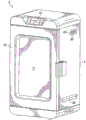
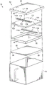
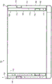
An embodiment 2 of the vertical electric cooking and smoking machine provided by the present invention is shown in fig. 1 and 2. The inventive electric cooking and smoking device 2 comprises: an upright rectangular box 4 having a vertical front opening 6; a cooking and smoking chamber 8 inside the upright box 4; a vertical front door 10, preferably having a window 11 therein, the vertical front door 10 being pivotally attached to the upright case 4 for opening and sealing closing the front opening 6 of the cooking and smoking chamber 8; a plurality of food holding shelves 12 removably positionable in the cooking and smoking chamber 8; an electric heating element assembly 14 spaced above the floor 16 of the cooking and smoking chamber 8; a smoke box 18 removably positionable on the heating element assembly 14; a removable tray or other container 20 adjacent the heating element assembly 14 for holding water or other liquid to maintain a desired level of moisture or flavorant vapor in the cooking and smoking chamber 8; and an electronic display and control panel 22 at the top of the box 4 above the door 10 for controlling the electric heating system and/or monitoring the temperature, cooking time and/or other parameters within the cooking and smoking chamber 8 in any desired manner.
Preferably, a plurality of food holding racks 12 are mounted on the opposing pressed side panels 15 using the common structure found in indoor ovens for holding cooking racks. However, the pressed detail 15 is not preferably integral with the side walls of the cooking and smoking chamber 8 as is otherwise typical in indoor ovens, but is more preferably attached as a separate part as depicted for additional flexibility in the manufacture and construction of the inventive apparatus 2.
As shown in FIGS. 1 and 2, two air intake vents 24 and 28 are provided in the lower portion of the cooking and smoking chamber 8. One of the lower air intake vents 24 is disposed through a left side wall 30 of the upright box 4 and the other air intake vent 28 is disposed through a right side wall 32 of the upright box 4, preferably directly opposite the left side intake vent 24. The air intake vents 24 and 28 are preferably located in the side walls 30 and 32 at or below the height of the heating element assembly 14.
Each of the side air intake vents 24 and 28 preferably comprises an opening (e.g., an elongated slit) or a series of openings 25 that (a) preferably extend laterally through at least 30% of the width of the side wall 30 or 32 (more preferably from about 75% to about 85% of the width of the side wall 30 or 32) in the side wall 30 or 32 of the upright box 4 and (b) are preferably centrally located in a lower portion of the side wall 30 or 32. Proportionally, the total flow (open) area provided by each of the air intake vents 24 and 28 per 2.94 cubic feet of volume of the cooking and smoking chamber 8 is preferably in the range of from about 1.0 to about 4.0 square inches, more preferably from about 2.0 to about 3.0 square inches. Although it is preferred that the air intake vents 24 and 28 be non-adjustable, the inventive apparatus 2 may alternatively include louvers, sliding covers, or other features for selectively varying the open area of the intake vents 24 and 28.
As further shown in FIGS. 1 and 2, two exhaust vents 34 and 36 are provided in the upper portion of the cooking and smoking chamber 8, preferably above the uppermost food support shelf 12 near the top of the cooking and smoking chamber 8. Preferably, one of the upper exhaust vents 34 is disposed through the left sidewall 30 of the upright tank 4 and the other upper exhaust vent 36 is disposed through the right sidewall 32 of the upright tank 4, preferably directly opposite the left exhaust vent 34.
Each of the exhaust vents 34 and 36 preferably: (a) is positioned from about 1.5 to about 6.5 inches from the upper end of the cooking and smoking chamber 8; (b) is positioned within a range of from about 2.5 to about 4.5 inches from the rear wall 38 of the cooking and smoking chamber 8; (c) having a louvered outer cover 40, the louvered outer cover 40 operative to direct smoke from a front end 94 of the cover assembly 82 of the smoke box 18 up and through the plurality of food holding shelves 12; and (d) providing a total effective proportional flow area through the lid 40 (if present) in the range of from about 4.0 to about 9.0 square inches, more preferably from about 6.0 to about 7.0 square inches per 2.94 cubic feet of volume of the cooking and smoking chamber 8.
The inventive placement of the lower pair of air intake vents 24 and 28 and the upper pair of exhaust vents 34 and 36 on each side of the cooking and smoking chamber 8 creates a balanced flow of ventilation air through the cooking and smoking chamber 8 on both sides, thereby providing a more even distribution of smoke and heat within the chamber 8. The cool, fresh outside air intake also reduced the CO as shown in the testing of inventive device 22And (4) generating. In these tests, the CO of the exhaust from the inventive cooking and smoking chamber 8 was above the space of the first two hours of operation2The concentration does not exceed 0.78%, normally between 0.10% and 0.15%. However, in the absence of air intake vents 24 and 28, CO is generated2Concentrations as high as 2.25%, normally between 1.3% and 2.1%.
Moreover, these tests additionally show that the cooling air flow provided by the inventive ventilation arrangement unexpectedly only slightly reduces the average internal temperature in the cooking and smoking chamber 8 for the first hour of operation, after which the temperature is similar. Although the reason for this surprising result is not known with certainty, it is believed to be the result of the predominant mode of cooking and smoking chamber 8 interior as a whole reaching a state of radiant heat equilibrium after one hour of operation with radiant energy becoming a heat transfer.
The visual effect of the use of the inventive ventilation arrangement with a large fuel load of the type described below is that the smoke of the wood does not become too dark or too rich but retains the desired light grayish blue color. The inventive venting arrangement also reduces the amount of smoke and water vapor condensing on the food surface during cooking.
In addition, the ventilation arrangement reduces the operating pressure within the cooking and smoking chamber 8 and, therefore, in conjunction with the larger size of the smoke box 18 (discussed below) and the inventive design and structure, allows for a much larger (up to as much as four cups or more) load of wood chips, pellets, or other debris to be used in the smoke box 18. Heretofore, in prior single top ventilated electric fume cupboards, the amount of wood chips that could be used in the cupboards was only about 3/4 cups or less due to the pressure caused by the partial combustion of the wood chips and the generation of smoke from the wood chips and the accumulation of unburned combustible hydrocarbons.
Moreover, by providing the lower air intake vents 24 and 28 and the upper exhaust vents 34 and 36 on both sides of the cooking and smoking chamber 8 of the inventive apparatus 2, the cooking and smoking chamber 8 is more uniformly filled with smoke without any voids in the cooking and smoking area. The inventive ventilation arrangement additionally assists in directing smoke upwardly through the food support shelf 12 to uniformly contact and cover the food product in a desired amount of smoke.
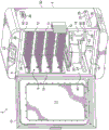
The improved electric heating element assembly 14 for use in the inventive vertical electric cooking and smoking machine 2 preferably comprises: a tray 46 having a reflective inner bottom surface 48; one or more electrical heating elements 50 positioned in the tray 46 above the reflective bottom surface 48; a rear accessory bracket 52; and a plurality of bottom legs 53. Rear bracket 52 secures heating element assembly 14 to rear wall 38 of cooking and smoking chamber 8 and provides an air gap between tray 46 and smoke box 18 and rear wall 38 of chamber 8. The bottom legs 53 preferably space the tray 46 about 2.25 inches above the bottom 16 of the cooking and smoking chamber 8. Also, a pair of spacers 54 and 57 project from the sides of the tray 46 for spacing the tray 46 and smoke box 18 from the inner surface of the right side wall 32 of the upright box 4 to provide an air gap of about 0.40 inches.
As seen in fig. 2 and 3, the position of the smoke box 18 relative to the heating element 50 is established with novel and effective features to control the heating of the wood chips or other chips contained in the box 18. This includes a unique retaining station 55 disposed on the tray 46, which retaining station 55 is used to receive the bottom of the smoke box 18 and retain the smoke box 18 above the electrical heating element 50.
The holding table 55 preferably includes: (a) a cover plate 56 at least partially covering the electric heating element 50 and serving as a bottom plate of the holding stage 55; (b) a plurality of spacers (standoffs) 58 protruding from the upper surface of the lid 56 to create an air gap 60 between the surface of the lid 56 and the bottom surface of the smoke box 18; (c) a receiving slot arrangement 65, the receiving slot arrangement 65 comprising two short upright side walls 62 and 64, a short upright rear wall 66 and an open front end 68 for receiving and aligning the bottom of the smoke box 18 on top of the cover plate 56; and (d) a reflective plate 70 extending rearwardly from the top of the short rear wall 66 of the smoke box receiving slot arrangement 65 for shielding the rear of the smoke box 18 from radiant energy emitted or reflected by the heating element 50 and/or the reflective surface 48.
The height of the standoffs 58 above the cover 56 is preferably at least 0.12 inches but no more than 0.25 inches. More preferably, the height of the stand-offs 58 is in the range of from about 0.10 inches to about 0.14 inches. By way of example, and not by way of limitation, the cap plate 56 is preferably formed from aluminized steel, mild steel, stainless steel, ceramic coated decarburized (de-carb) steel, cast iron, or cast aluminum, and the standoffs 58 are preferably formed from aluminized steel, mild steel, stainless steel, ceramic coated decarburized, cast iron, or cast aluminum.
Instead of the use of standoffs 58, a washer, a screw assembly, an extruded turned-over hole, a square extrusion, a plurality of elongated standoffs, for example, in the receiving slot arrangement 65 or in the bottom of the smoke box 18 may alternatively be used to create or provide a space between the cover plate 56 and the bottom of the smoke box 18.
In the inventive upright cooking and smoking device 2, a cover plate 56 that acts as a shield over the heating element 50, spacers (stand-offs) 58 that elevate the bottom of the smoke box 18 away from the cover plate 56, spacers 54 and 57 that provide an air gap between the sides of the smoke box 18 and the inside walls of the cooking and smoking chamber 8, and a rear reflector 70 that shields the rear of the smoke box 18 work together to: (a) sufficiently reduce the temperature and heat transfer at the bottom of the smoke box 18 to increase the smoking time; (b) providing uniform heating at the bottom of the smoke box 18 so that the entire lower bed of wood chips in the box 18 will start at the same time; and (c) eliminating hot pockets within the smoke box 18.
An embodiment 18 of the inventive smoke generating box for use in the upright electric cooking and smoking device 2 is illustrated in fig. 3-6. The inventive smoke box 18 comprises: a rectangular box 75 having a longitudinal axis 76; a front handle 78; a cold plate or "false bottom" 80 that fits within the rectangular box 75; and a removable cover assembly 82. The false bottom 80 has a pair of downwardly extending side spacer rails 84 and 86 that support and space the false bottom 80 above the bottom 81 of the tank 75 to provide an air gap 88 between the false bottom 80 and the true bottom 81 of the tank 75 of from about 0.20 inches to about 0.50 inches, more preferably from about 0.33 inches to about 0.38 inches. This additional air gap 88 in the bottom of the box 75 operates to further stabilize the heating of the wood chips or other wood chips in the smoke box 18.
The rectangular box 75 will preferably be sized to hold at least four cups of wood chips or other debris above the false bottom 80. The interior of the rectangular box 75 will preferably have: (a) a longitudinal length in a range from about 6.0 inches to about 6.25 inches; (b) a width in a range from about 4.25 inches to about 4.40 inches; and (c) a height in the range of from about 3.0 inches to about 3.25 inches.
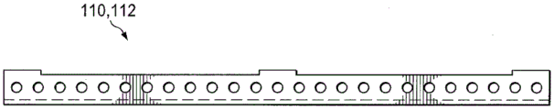
The lid assembly 82 of the inventive smoke generating box 18 comprises: (a) a lower cover member 90, the lower cover member 90 having a row of transverse smoke ports 92 extending through the lower cover member 90 adjacent a front end 94 of the cover member 82; (b) an upper cover 96, the upper cover 96 having a row of transverse smoke ports 98 extending through the upper cover 96 adjacent the front end 94 of the cover assembly 82; (c) a middle cover 100 positioned between the upper cover 96 and the lower cover 90, the middle cover 100 having a row of lateral smoke ports 102 extending through the middle cover 100 adjacent a rear end 104 of the cover assembly 82; (d) a lower horizontal flow gap 106 formed between the lower cover 90 and the middle cover 100; (e) an upper horizontal flow gap 108 formed between the middle cap 100 and the upper cap 96; (f) a lower flow rail member 110 extending laterally in the lower flow gap 106; and (g) an upper flow rail member 112 extending laterally in the upper flow gap 108.
Each of the laterally extending upper and lower flow rail members 110 and 112 includes a pair of parallel pass-through rails 110a and 110b and 112a and 112b that extend laterally across and block the upper and lower horizontal flow gaps 106 and 108. The upstream rail 110a, 112a of each rail member 110, 112 has a series of smoke inlet apertures 114, 116 disposed therethrough. The downstream tracks 110b, 112b of each track member 110, 112 have a series of smoke outlet apertures 118, 120 disposed therethrough. Preferably, the smoke outlet apertures 118, 120 of each rail member 110, 112 are not aligned with the smoke inlet apertures 114, 116 of the rail members 110, 112. Thus, smoke flowing into the inlet apertures 114, 116 cannot flow directly (e.g., in a straight line) through the outlet apertures 118, 120, but instead is forced to change direction at least to some extent within the rail members 110, 112.
The lower track member 110 is preferably positioned in the lower flow gap 106 at a distance from the inlet end 122 to the outlet end 124 of the lower flow gap 106 of from about 1/3 to about 4/5, more preferably from about 1/2 to about 3/4. Similarly, the upper track member 112 is preferably positioned in the upper flow gap 108 at a distance from the inlet end 126 to the outlet end 128 of the upper flow gap 108 of from about 1/3 to about 4/5, more preferably from about 1/2 to about 3/4.
For each of the lower cover 90, upper cover 96 and middle cover 100, the total proportional flow area of the smoke ports of the respective row 92, 98 or 102 disposed therethrough will preferably be in the range of from about 0.9 to about 2.6 square inches, more preferably from about 1.3 to about 1.6 square inches per 80 cubic inch of volume of the cooking and smoking chamber 18.
The lower flow gap 106 and the upper flow gap 108 formed between the covers will preferably each have a height in the range of from about 0.10 to about 0.17 inches, more preferably from about 0.12 to about 0.15 inches.
The total proportional flow area of the smoke inlet or smoke outlet apertures 114, 116, 118, or 120 disposed through each of the separate upstream and downstream tracks 110a, 110b, 112a, or 112b of the track members 110 and 112 will preferably be in the range of from about 0.25 to about 1.0 square inches, more preferably from about 0.44 to about 0.62 square inches, per 80 cubic inches of volume of the cooking and smoking chamber 18. For each of the track members 110 and 112, the distance between its upstream track 110a, 112a and downstream track 110b, 112b will preferably be in the range of from about 0.25 to about 0.50 inches, more preferably from about 0.36 to about 0.40 inches.
In the inventive smoke box 18, smoke produced by the wood chips in the heating box 75 is forced to flow along a defined circuitous flow path 130 in which the smoke travels into the smoke port 92 of the lower cover member 90, through the first portion of the lower horizontal flow gap 106 to the lower track member 110, through the offset apertures 110a and 110b of the lower track member, from the lower track member 110 to the smoke port 102 of the middle cover member 100, through the first portion of the upper horizontal flow gap 108 to the upper track member 112, through the offset apertures 112a and 112b of the upper track member 112, from the upper track member 112 to the smoke port 98 of the upper cover member 96, and out of the smoke port 98 into the cooking and smoking chamber 2 of the inventive vertical electrical appliance.
This circuitous path 130 acts as a flame suppression mechanism to prevent and contain any fire in the smoke box and additionally provides cooling and mixing of the generated smoke in the inventive smoke box 18 so that the smoke exiting the lid outlet opening 98 has a relatively uniform temperature and smoke concentration. The length of the circuitous path 130 also allows the temperature of the smoke to be hot enough to maintain the smoke particles suspended in the atmosphere, but cold enough to remain well below any ignition point as the smoke exits the smoke box 18.
An alternative embodiment 150 of the inventive smoke box is illustrated in figures 7 and 8. The inventive smoke box 150 is substantially identical to the inventive smoke box 18, except that instead of providing a circuitous exit path for smoke through the lid of the box, a substantially similar flow path 152 is provided in one, two, three or all four of the vertical sides 154, 156, 158, 160 of the inventive smoke box 150.
In the inventive smoke box 150, each of the one or more vertical sides in which the circuitous smoke exit path 152 is disposed comprises: (a) an inner vertical wall 162 having a discharge port 164, the discharge port 164 extending across an upper end portion of the inner vertical wall 162; (b) an outer vertical wall 166 having an open upper end 168; (c) a middle vertical wall 170 positioned between the inner vertical wall 162 and the outer vertical wall 166 and having a discharge outlet 175, the discharge outlet 175 extending across a bottom portion of the middle vertical wall 170; (d) an inner vertical flow gap 172 formed between the inner vertical wall 162 and the middle vertical wall 170; (e) an outer vertical flow gap 174 formed between the middle vertical wall 170 and the outer vertical wall 166; (f) an inner flow rail member 176 extending horizontally in the inner flow gap 172; (g) an outer flow rail member 178 extending horizontally in the outer vertical flow gap 174; and (h) a row of smoke evacuation ports 180 formed through the top of the lid 182 of the bin along the edge of the lid 182 for placement over the open upper end 168 of the outer vertical wall 166.
Thus, in the circuitous flow path 152 defined in the inventive smoke box 150, smoke is forced to flow into the smoke ports 164 at the upper end of the inner vertical wall 162, downwardly through the inner flow gap 172 to the inner track member 176, from the inner track member 176 to the flow ports at the bottom of the middle vertical wall 170, upwardly through the outer vertical flow gap 174 to the outer track member 178, and from the outer track member 178 to the smoke outlet 180 of the lid 182 and out of the smoke outlet 180 of the lid 182. Alternatively, the smoke may exit through a side exhaust provided at the upper end of the outer wall 166 rather than through the lid 182.
The flow port areas for the walls and lid of the circuitous flow path 152 of the inventive smoke box 150, the rail member flow port areas, and the flow gap widths will preferably be the same as those of the flow path 130 provided in the lid assembly of the inventive smoke box 18.
Accordingly, the present invention is well adapted to carry out the objects and attain the ends and advantages mentioned as well as those inherent therein. Although a presently preferred embodiment has been described for purposes of this disclosure, many variations and modifications will be apparent to those of ordinary skill in the art. Such changes and modifications are intended to be included within the scope of the present invention.

Claims (21)

1.一种用于烹饪和烟熏食物的设备,其包含:1. An apparatus for cooking and smoking food, comprising: 具有左侧壁、右侧壁、后壁、前开口和底板的竖直延伸的烹饪及烟熏室;a vertically extending cooking and smoking chamber having a left side wall, a right side wall, a rear wall, a front opening and a floor; 能定位在所述前开口上用于关闭和打开所述前开口的门;a door positionable on the front opening for closing and opening the front opening; 容纳在所述烹饪及烟熏室中的烟箱,所述烟箱包括:a smoke box contained in the cooking and smoking chamber, the smoke box comprising: 容器,container, 能放置在容器上的盖,lids that can be placed on containers, 在容器中的内燃烧区域,所述内燃烧区域用于在缺氧的环境中燃烧木屑或其它碎片以产生烟,和an inner combustion zone in the vessel for burning wood chips or other debris in an oxygen-deficient environment to produce smoke, and 在所述盖中和/或在所述容器的一个或多个竖直侧壁中的排气流动组件,其中所述排气流动组件限定用于烟的迂回的排气流动路径,其中,烟必须沿第一方向从由所述排气流动组件形成的内流动间隙的入口端到出口端流动,并且然后必须沿与所述第一方向不同的第二方向从由所述排气流动组件形成的外流动间隙的入口端到出口端流动。An exhaust flow assembly in the lid and/or in one or more vertical side walls of the container, wherein the exhaust flow assembly defines a circuitous exhaust flow path for smoke, wherein the smoke must flow in a first direction from the inlet end to the outlet end of the inner flow gap formed by the exhaust gas flow assembly, and must then flow in a second direction different from the first direction from the exhaust gas flow assembly formed by the exhaust gas flow assembly The outer flow gap flows from the inlet end to the outlet end. 2.如权利要求1所述的设备,其中所述设备还包含两个空气进气通风口和两个排气通风口,其中,所述空气进气通风口中的第一空气进气通风口设置成穿过所述右侧壁的下部部分,所述空气进气通风口中的第二空气进气通风口设置成穿过所述左侧壁的下部部分,所述排气通风口中的第一排气通风口设置成穿过所述右侧壁的上部部分,并且所述排气通风口中的第二排气通风口设置成穿过所述左侧壁的上部部分。2. The apparatus of claim 1, wherein the apparatus further comprises two air intake vents and two exhaust vents, wherein a first of the air intake vents is provided through the lower portion of the right side wall, a second one of the air intake vents is provided through the lower portion of the left side wall, a first row of the exhaust vents An air vent is provided through the upper portion of the right side wall, and a second one of the exhaust vents is provided through the upper portion of the left side wall. 3.如权利要求2所述的设备,其中:3. The apparatus of claim 2, wherein: 所述第一空气进气通风口包含水平延伸穿过所述右侧壁的水平宽度的至少30%的一个或一系列开口,并且the first air intake vent includes one or a series of openings extending horizontally through at least 30% of the horizontal width of the right side wall, and 所述第二空气进气通风口包含水平延伸穿过所述左侧壁的水平宽度的至少30%的一个或一系列开口。The second air intake vent includes one or a series of openings extending horizontally through at least 30% of the horizontal width of the left side wall. 4.如权利要求2所述的设备,其中,所述第一空气进气通风口和第二空气进气通风口各自具有在所述烹饪及烟熏室的每2.94 立方英尺的体积的从1.0到4.0平方英寸范围中的开口流动面积。4. The apparatus of claim 2, wherein the first and second air intake vents each have from 1.0 per 2.94 cubic feet of volume in the cooking and smoking chamber to an open flow area in the range of 4.0 square inches. 5.如权利要求4所述的设备,其中,所述第一排气通风口和第二排气通风口各自具有在所述烹饪及烟熏室的每2.94 立方英尺的体积的从4.0到9.0平方英寸范围中的流动面积。5. The apparatus of claim 4, wherein the first and second exhaust vents each have from 4.0 to 9.0 per 2.94 cubic feet of volume in the cooking and smoking chamber Flow area in square inches. 6.如权利要求5所述的设备,其中,所述第一排气通风口和第二排气通风口各自具有百叶式的盖。6. The apparatus of claim 5, wherein the first exhaust vent and the second exhaust vent each have a louvered cover. 7.如权利要求2所述的设备,其中:7. The apparatus of claim 2, wherein: 所述烹饪及烟熏室具有被定位在其中的最靠上的食物支撑架,并且the cooking and smoking chamber has an uppermost food support rack positioned therein, and 所述第一排气通风口和第二排气通风口被定位在高于所述最靠上的食物支撑架的高度的高度处。The first and second exhaust vents are positioned at a height above the height of the uppermost food support rack. 8.如权利要求1所述的设备,其中所述设备还包含:8. The apparatus of claim 1, wherein the apparatus further comprises: 在烹饪及烟熏室中的一个或多个电加热元件,和one or more electric heating elements in the cooking and smoking chamber, and 保持台,所述保持台包括:a holding table, the holding table comprising: 盖板,所述盖板至少部分覆盖所述一个或多个电加热元件,和a cover plate at least partially covering the one or more electrical heating elements, and 从盖板的上表面突出的多个间隔件,所述烟箱能被放置在所述多个间隔件上以在所述盖板的上表面与所述烟箱的底表面之间提供空气间隙。a plurality of spacers protruding from the upper surface of the cover plate on which the smoke box can be placed to provide an air gap between the upper surface of the cover plate and the bottom surface of the smoke box . 9.如权利要求1所述的设备,其中,所述烟箱9. The apparatus of claim 1, wherein the smoke box 还包含:Also contains: 所述容器具有没有开口穿过其中的真正底部,以及the container has a true bottom with no opening therethrough, and 在所述容器的内部中的假底部,所述假底部在所述容器的所述真正底部上方间隔开使得底部空气空间在容器中被限定在所述容器的所述假底部与所述真正底部之间,所述假底部不具有穿过其中的开口。A false bottom in the interior of the container spaced above the true bottom of the container such that a bottom air space is defined in the container between the false bottom and the true bottom of the container In between, the false bottom has no opening therethrough. 10.如权利要求1所述的设备,其中,所述烟箱还包含:10. The apparatus of claim 1, wherein the smoke box further comprises: 在所述内流动间隙中横向延伸的第一流动轨道件,当烟从内流动间隙的入口端行进到出口端时,所述第一流动轨道件至少短暂改变烟的排气流动路径,以及a first flow track member extending laterally in the inner flow gap that at least briefly changes the exhaust flow path of the smoke as it travels from the inlet end to the outlet end of the inner flow gap, and 在所述外流动间隙中横向延伸的第二流动轨道件,当烟从外流动间隙的入口端行进到出口端时,所述第二流动轨道件至少短暂改变烟的排气流动路径。A second flow track member extending laterally in the outer flow gap changes the exhaust flow path of the smoke at least briefly as the smoke travels from the inlet end to the outlet end of the outer flow gap. 11.如权利要求10所述的设备,其中,所述第一流动轨道件和第二流动轨道件各自都包括上游轨道和平行的下游轨道,所述上游轨道和下游轨道各自具有用于烟流动的多个孔,其中下游轨道中的孔与上游轨道中的孔不对准。11. The apparatus of claim 10, wherein each of the first and second flow track members includes an upstream track and a parallel downstream track, each of the upstream and downstream tracks having for smoke flow A plurality of holes in which the holes in the downstream track are not aligned with the holes in the upstream track. 12.如权利要求10所述的设备,其中,所述排气流动组件被形成在所述烟箱的盖中。12. The apparatus of claim 10, wherein the exhaust flow assembly is formed in a cover of the smoke box. 13.如权利要求10所述的设备,其中,所述排气流动组件被形成在所述烟箱的一个或多个竖直侧壁之一中。13. The apparatus of claim 10, wherein the exhaust flow assembly is formed in one of the one or more vertical side walls of the smoke box. 14.如权利要求10所述的设备,其中,所述排气流动组件被形成在所述烟箱的多个竖直侧壁中。14. The apparatus of claim 10, wherein the exhaust flow assembly is formed in a plurality of vertical side walls of the smoke box. 15.一种烟箱设备,其包含:15. A smoke box device comprising: 具有内燃烧区域的容器,所述内燃烧区域用于在缺氧环境中燃烧木屑或其它碎片以产生烟,a vessel having an inner combustion zone for burning wood chips or other debris in an oxygen-deficient environment to produce smoke, 能放置在容器上的盖,和a lid that can be placed over the container, and 在所述盖中和/或在所述容器的一个或多个竖直侧壁中的排气流动组件,其中所述排气流动组件限定用于烟的迂回的排气流动路径,其中,烟必须沿第一方向从由所述排气流动组件形成的内流动间隙的入口端到出口端流动,并且然后必须沿与所述第一方向不同的第二方向从由所述排气流动组件形成的外流动间隙的入口端到出口端流动。An exhaust flow assembly in the lid and/or in one or more vertical side walls of the container, wherein the exhaust flow assembly defines a circuitous exhaust flow path for smoke, wherein the smoke must flow in a first direction from the inlet end to the outlet end of the inner flow gap formed by the exhaust gas flow assembly, and must then flow in a second direction different from the first direction from the exhaust gas flow assembly formed by the exhaust gas flow assembly The outer flow gap flows from the inlet end to the outlet end. 16.如权利要求15所述的烟箱设备,其中,所述容器具有没有穿过其中的开口的真正底部、和在容器内部的假底部,所述假底部在所述容器的所述真正底部上方间隔开使得底部空气空间在容器中被限定在所述容器的所述假底部与所述真正底部之间,所述假底部不具有穿过其中的开口。16. The smoke box apparatus of claim 15, wherein the container has a true bottom without an opening therethrough, and a false bottom inside the container, the false bottom at the true bottom of the container The space above is such that a bottom air space is defined in the container between the false bottom and the true bottom of the container, the false bottom having no opening therethrough. 17.如权利要求15所述的烟箱设备,其中,所述烟箱设备还包含:17. The smoke box apparatus of claim 15, wherein the smoke box apparatus further comprises: 在所述内流动间隙中横向延伸的第一流动轨道件,当烟从内流动间隙的入口端行进到出口端时,所述第一流动轨道件至少短暂改变烟的排气流动路径,以及a first flow track member extending laterally in the inner flow gap that at least briefly changes the exhaust flow path of the smoke as it travels from the inlet end to the outlet end of the inner flow gap, and 在所述外流动间隙中横向延伸的第二流动轨道件,当烟从外流动间隙的入口端行进到出口端时,所述第二流动轨道件至少短暂改变烟的排气流动路径。A second flow track member extending laterally in the outer flow gap changes the exhaust flow path of the smoke at least briefly as the smoke travels from the inlet end to the outlet end of the outer flow gap. 18.如权利要求17所述的烟箱设备,其中,所述第一流动轨道件和第二流动轨道件各自都包括上游轨道和平行的下游轨道,所述上游轨道和下游轨道各自具有用于烟流动的多个孔,其中下游轨道中的孔与上游轨道中的孔不对准。18. The smoke box apparatus of claim 17, wherein the first and second flow track members each include an upstream track and a parallel downstream track, the upstream and downstream tracks each having a A plurality of holes for smoke flow, wherein the holes in the downstream track are not aligned with the holes in the upstream track. 19.如权利要求17所述的烟箱设备,其中,所述排气流动组件被形成在所述容器的盖中。19. The smoke box apparatus of claim 17, wherein the exhaust flow assembly is formed in a lid of the container. 20.如权利要求17所述的烟箱设备,其中,所述排气流动组件被形成在所述容器的一个或多个竖直侧壁之一中。20. The smoke box apparatus of claim 17, wherein the exhaust flow assembly is formed in one of the one or more vertical side walls of the container. 21.如权利要求17所述的烟箱设备,其中,所述排气流动组件被形成在所述容器的多个竖直侧壁中。21. The smoke box apparatus of claim 17, wherein the exhaust flow assembly is formed in a plurality of vertical side walls of the container.
CN201680017847.8A 2015-03-25 2016-03-21 Vertical electric cooking and smoking machine and smoke box Expired - Fee Related CN107683091B (en)

Applications Claiming Priority (3)

Application Number Priority Date Filing Date Title
US201562138002P 2015-03-25 2015-03-25
US62/138002 2015-03-25
PCT/US2016/023419 WO2016154114A1 (en) 2015-03-25 2016-03-21 Vertical electric cooker and smoker and smoke box

Publications (2)

Publication Number Publication Date
CN107683091A CN107683091A (en) 2018-02-09
CN107683091B true CN107683091B (en) 2021-09-03

Family

ID=56977739

Family Applications (1)

Application Number Title Priority Date Filing Date
CN201680017847.8A Expired - Fee Related CN107683091B (en) 2015-03-25 2016-03-21 Vertical electric cooking and smoking machine and smoke box

Country Status (6)

Country Link
US (1) US10426176B2 (en)
EP (1) EP3273786B8 (en)
CN (1) CN107683091B (en)
CA (1) CA2977120C (en)
DK (1) DK3273786T3 (en)
WO (1) WO2016154114A1 (en)

Families Citing this family (32)

* Cited by examiner, † Cited by third party
Publication number Priority date Publication date Assignee Title
US10595540B1 (en) * 2015-05-01 2020-03-24 David B. Knight & Associates, Inc. Barbecue oven having circulation control
EP3104086B1 (en) * 2015-06-11 2019-09-18 Electrolux Professional S.p.A. Flavoring device for use in a cooking chamber
EP3104085B1 (en) * 2015-06-11 2025-08-20 Electrolux Professional S.p.A. Flavoring device for use in a cooking chamber
US10045546B2 (en) * 2016-02-18 2018-08-14 Masterbuilt Manufacturing, Llc Electric food smoker
DE202018006410U1 (en) 2017-08-09 2020-04-23 Sharkninja Operating Llc Cooking device and components thereof
US10624358B2 (en) * 2017-12-05 2020-04-21 Lem Products Holding Llc Electric smoker
USD914447S1 (en) 2018-06-19 2021-03-30 Sharkninja Operating Llc Air diffuser
USD883015S1 (en) 2018-08-09 2020-05-05 Sharkninja Operating Llc Food preparation device and parts thereof
USD903413S1 (en) 2018-08-09 2020-12-01 Sharkninja Operating Llc Cooking basket
USD934027S1 (en) 2018-08-09 2021-10-26 Sharkninja Operating Llc Reversible cooking rack
USD883014S1 (en) 2018-08-09 2020-05-05 Sharkninja Operating Llc Food preparation device
US20190254476A1 (en) 2019-02-25 2019-08-22 Sharkninja Operating Llc Cooking device and components thereof
WO2020176477A1 (en) 2019-02-25 2020-09-03 Sharkninja Operating Llc Cooking system with guard
USD918654S1 (en) 2019-06-06 2021-05-11 Sharkninja Operating Llc Grill plate
USD982375S1 (en) 2019-06-06 2023-04-04 Sharkninja Operating Llc Food preparation device
AU2020314733B2 (en) 2019-07-15 2022-07-14 Sharkninja Operating Llc Cooking device and components thereof
US12102098B2 (en) 2019-08-07 2024-10-01 Haier Us Appliance Solutions, Inc. Smoke generating assembly for an indoor smoker
CN110915877B (en) * 2019-12-27 2021-11-19 广东美的厨房电器制造有限公司 Cooking appliance control method and device and cooking appliance
US11647861B2 (en) 2020-03-30 2023-05-16 Sharkninja Operating Llc Cooking device and components thereof
US20220007662A1 (en) * 2020-07-07 2022-01-13 Zhejiang Fudeer Electric Appliance Co., Ltd. Smoking Oven
IT202000026765A1 (en) * 2020-11-10 2022-05-10 Costruzioni Mecc Paterno S R L SMOKING AND COOKING APPARATUS
US12137838B2 (en) 2020-12-30 2024-11-12 Sharkninja Operating Llc Cooking device and components thereof
US12564196B2 (en) 2020-12-30 2026-03-03 Sharkninja Operating Llc Smoke functionality in electric grill-type appliance
CA3245428A1 (en) 2022-03-03 2025-01-21 GMG Products, LLC A bbq oven
US12289508B2 (en) 2022-03-18 2025-04-29 GMG Products, LLC Detachable camera for a smoker or grill
US12446730B2 (en) 2022-03-29 2025-10-21 Sharkninja Operating Llc Grill system with smoke assembly
US12478213B2 (en) 2022-03-29 2025-11-25 Sharkninja Operating Llc Grill system with smoke assembly
US12070042B2 (en) 2022-12-12 2024-08-27 Sharkninja Operating Llc Grill systems
US12035725B2 (en) 2022-12-12 2024-07-16 Sharkninja Operating, Llc Grill systems
USD1063483S1 (en) 2023-06-15 2025-02-25 Sharkninja Operating Llc Cooking device
US12359808B1 (en) 2024-04-30 2025-07-15 GMG Products, LLC Variable fuel cooker
WO2025255708A1 (en) * 2024-06-11 2025-12-18 Haier Us Appliance Solutions, Inc. Indoor smoker and exhaust system for the same

Citations (13)

* Cited by examiner, † Cited by third party
Publication number Priority date Publication date Assignee Title
US4307659A (en) * 1978-03-31 1981-12-29 Mtm Corporation Barbecue oven
CN2036387U (en) * 1988-10-17 1989-04-26 丁士来 Casing type water-boiling kettle
US4924071A (en) * 1987-07-06 1990-05-08 Woodroast Systems, Inc. Oven
US4934260A (en) * 1989-09-08 1990-06-19 Blevins Mack F Food cooker and smoker
JPH02255039A (en) * 1989-03-28 1990-10-15 Tsu Kikai Kigu Kogyo Kyodo Kumiai Smoking system
US5588355A (en) * 1995-04-17 1996-12-31 Mead; Julian E. Knockdown compactable food smoker and method of use thereof
US5782165A (en) * 1992-09-01 1998-07-21 Ever Splendor Enterprises Co., Ltd. Multi-purpose cooking apparatus
CN2405523Y (en) * 1999-12-22 2000-11-15 昕昌兴企业股份有限公司 Electronic safety meat roaster
CN2544532Y (en) * 2002-03-26 2003-04-16 广东德豪润达电气股份有限公司 Electric heating device with smoking function
CN2811800Y (en) * 2005-06-08 2006-08-30 何均奇 Environment-friendly smoke exhausting and purifying device
CN202311122U (en) * 2011-11-24 2012-07-11 王朝晖 Low-temperature smoke generator
CN103960989A (en) * 2013-02-05 2014-08-06 阿尔菲尼迪美国有限责任公司 Apparatus For Cooking And Smoking Food
CN204047818U (en) * 2014-09-25 2014-12-31 松阳县诚天和食品有限公司 A kind of bacon machine

Family Cites Families (132)

* Cited by examiner, † Cited by third party
Publication number Priority date Publication date Assignee Title
US1399704A (en) 1921-12-06 Cooking-stove
GB191423552A (en) 1911-12-04 1915-03-18 South Metropolitan Gas Co Improvements in Gas Ovens.
US1158986A (en) 1914-02-21 1915-11-02 Carl G Cronwall Gas-burner.
US2001615A (en) 1932-01-19 1935-05-14 Karten William Theodore Baking vessel
GB432481A (en) 1933-02-23 1935-07-22 Bolinder Fabriks Aktiebolag Improvements in or relating to cooking stoves
GB562136A (en) 1942-11-18 1944-06-20 Herbert Gordon Darby Improvements in gas cooking stoves
GB576377A (en) 1944-04-14 1946-04-01 James Forbes Jones An improved gas-heated oven stove
FR1129123A (en) 1955-07-13 1957-01-16 Liotard Metallurg Gas heater, emitter of red and infrared rays
CH371237A (en) 1957-10-24 1963-08-15 Pozzi Arnaldo Gas burner with a radiator
US3277948A (en) 1960-09-09 1966-10-11 Thermal Engineering Corp Radiant burner utilizing flame quenching phenomena
US3155814A (en) 1961-07-31 1964-11-03 Radiant Electronic Products Co Infrared radiant heating oven
FR1387132A (en) 1962-12-11 1965-01-29 Hupp Corp Improvement in infrared radiation heating
US3245458A (en) 1962-12-11 1966-04-12 Hupp Corp Radiant gas burner
US3437415A (en) 1966-08-22 1969-04-08 Graig & Seeley Ltd Radiant gas burner
US3517602A (en) 1968-07-08 1970-06-30 James P Horton Barbecue cooker
US3561902A (en) 1968-09-19 1971-02-09 Willie H Best Radiant burner
US3586825A (en) 1968-10-03 1971-06-22 Modern Maid Inc Flush top cooking unit with ventilating means
US3683058A (en) 1969-08-25 1972-08-08 Maurice Partiot Infrared burners and high efficiency radiant plates
US3663798A (en) 1969-08-25 1972-05-16 Thermo Electron Corp An infrared heating surface
FR2076610A5 (en) 1970-01-21 1971-10-15 Gestion Immob Mob
US3788301A (en) 1972-07-31 1974-01-29 R Terry Smoke generator
US3941117A (en) 1974-10-21 1976-03-02 Owens-Illinois, Inc. Cooktop for a gas-fired range
US4024839A (en) 1975-03-10 1977-05-24 Columbia Gas System Service Corporation Gas-fired smooth top range
US4057670A (en) 1976-01-28 1977-11-08 Jenaer Glaswerk Schott & Gen. Cooking surfaces of glass-ceramic plates with layers with different values for radiation transmission
US4039275A (en) 1976-02-23 1977-08-02 Mcgettrick Charles A Infrared energy generator with orifice plate
JPS5343025U (en) 1976-09-18 1978-04-13
US4207456A (en) 1977-11-04 1980-06-10 Best Willie H Electrical infrared radiant heater
US4426792A (en) 1978-06-16 1984-01-24 Best Willie H High turbulance heat transfer oven
US4235023A (en) 1978-06-16 1980-11-25 Best Willie H High heat transfer oven
US4546553B1 (en) 1978-06-16 1993-04-13 Radiant wall oven and process of drying coated objects
US4276869A (en) 1979-04-16 1981-07-07 Kern Eugene F Barbecue grill slab
US4403541A (en) 1979-05-29 1983-09-13 Ducane Heating Corporation Heat trapping cooking grill
FI61562C (en) 1979-12-14 1982-08-10 Jorma Wallasvaara SPIS
US4321857A (en) 1980-04-08 1982-03-30 Best Willie H Infrared gas grill
US4403597A (en) 1981-01-16 1983-09-13 Miller Don J Heat transfer device
US4437833A (en) 1981-03-05 1984-03-20 Red-Ray Manufacturing Company, Inc. Infrared radiating burner article
EP0076291A1 (en) 1981-04-10 1983-04-13 BERG, Keith Edward Self cleaning indoor barbecue griller
SE8200685L (en) 1982-02-05 1983-08-06 Electrolux Ab WITH INFRARED RADIATION WORKING HOUSE OVEN
FR2534353A1 (en) 1982-10-11 1984-04-13 Vaneecke Solaronics ALVEOLED RADIANT FACING PLATE FOR RADIANT BURNER
US4537492A (en) 1983-07-07 1985-08-27 Itek Corporation Heater-drier for fusing toner images on wet printing plates
IT1214334B (en) 1983-11-30 1990-01-10 Dario Bernardi GRILL FOR THE COOKING OF REFLECTED HEATS
US4715356A (en) 1985-07-26 1987-12-29 Reynolds Howard S Gas burner with heat reflective radiants for controlled heat concentration
GB8526068D0 (en) 1985-10-22 1985-11-27 Thorn Emi Appliances Cooking apparatus
JPH0663625B2 (en) 1986-09-24 1994-08-22 株式会社日本ケミカル・プラント・コンサルタント Far infrared radiation device
US4785552A (en) 1987-07-08 1988-11-22 Best Willie H Convection stabilized radiant oven
JPH0625919Y2 (en) 1988-03-15 1994-07-06 千住金属工業株式会社 Infrared heater
US4839502A (en) 1988-03-21 1989-06-13 Swanson David L Cooking apparatus
US4889972A (en) 1988-08-11 1989-12-26 Chang Chia C Multi-functional electrically activated stove
US4886044A (en) 1988-08-17 1989-12-12 Best Willie H Infrared gas grill
US4909137A (en) 1988-11-28 1990-03-20 Giuliano Brugnoli Cooking grill grease catcher
CA2005415C (en) 1989-01-10 1994-03-01 Willie H. Best High efficiency gas burner assembly
US4979436A (en) 1989-01-23 1990-12-25 Mcgowan Michael J Smoking and baking apparatus
US5230161A (en) 1989-03-28 1993-07-27 Haden Schweitzer Corporation Apparatus and process for generating radiant energy
DE3912124C1 (en) 1989-04-13 1990-07-12 Schott Glaswerke, 6500 Mainz, De
US4960977A (en) 1989-04-20 1990-10-02 G. S. Blodgett Co., Inc. Infra-red baking oven
US4883423A (en) 1989-05-08 1989-11-28 Carrier Corporation Method for making an infrared burner
US5761990A (en) 1989-06-30 1998-06-09 Stewart, Deceased; James M. Barbecue cooker apparatus and process
US5062408A (en) 1990-04-19 1991-11-05 Middleby Corporation Charbroiler
US5277106A (en) 1990-07-02 1994-01-11 The Thermos Company, Inc. Easily assembled barbecue grill with heat distribution plate
US5218952A (en) 1990-10-29 1993-06-15 Neufeldt Allen A Radiant heating apparatus
US5594999A (en) 1991-05-15 1997-01-21 Haden Schweitzer Corporation Radiant wall oven and process for generating infrared radiation having a nonuniform emission distribution
US5111803A (en) 1991-07-03 1992-05-12 Barbecue Innovations Incorporated Flare reduction buffer for gas barbecues
SE468876B (en) 1991-07-08 1993-04-05 Staalhane Henrik DEVICE ON GAS OIL GRILL
US5322007A (en) 1991-08-15 1994-06-21 Heat And Control, Inc. Compact, high-capacity oven
US5240411A (en) 1992-02-10 1993-08-31 Mor-Flo Industries, Inc. Atmospheric gas burner assembly
US5306138A (en) 1992-03-10 1994-04-26 Best Willie H Method and apparatus for incinerating combustibles carried by an air stream
US5279277A (en) 1992-08-03 1994-01-18 Barker Gordon R Heat radiating element and drippings shield for gas-fired barbecues
AU673831B2 (en) 1992-09-29 1996-11-28 Thermos Company, The Lifestyle barbecue grill
US5320086A (en) 1993-02-16 1994-06-14 Majco Building Specialties, L.P. Direct vent gas appliance with vertical and horizontal venting
DE4326945C2 (en) 1993-08-11 1996-10-24 Schott Glaswerke Control device for the gas supply to a gas cooking device with gas radiation burners arranged under a continuous cooking surface
US5313877A (en) 1993-09-21 1994-05-24 Holland Robert B Barbecue grill with controlled heat distribution
US5567459A (en) 1993-10-12 1996-10-22 Centro De Investigacion Y De Estudios Avanzados-Del I.P.N. Method of cooking corn dough tortillas using infrared radiation
US5711661A (en) 1994-05-03 1998-01-27 Quantum Group, Inc. High intensity, low NOx matrix burner
US5488897A (en) 1994-05-11 1996-02-06 Griller's World Inc. Cooking apparatus
US5599471A (en) 1994-06-13 1997-02-04 Zaidman; Mikhail Compact smoking oven
US5494003A (en) 1994-09-01 1996-02-27 Alzeta Corporation Water heater with perforated ceramic plate infrared burner
US5566607A (en) 1995-05-11 1996-10-22 Schleimer; Norman Grill with grease deflector assembly
US6213757B1 (en) 1995-06-07 2001-04-10 Quantum Group Inc. Advanced emissive matrix combustion
US5676043A (en) 1995-10-03 1997-10-14 Best; Willie H. Griddle assembly having discrete cooking zones
US5513623A (en) 1995-10-13 1996-05-07 Hong; Young P. Portable gas cooking device
US5890422A (en) 1996-06-24 1999-04-06 Grill-N-Roast, Inc. Convertible drip pan and method of using the same
US5879154A (en) 1996-11-18 1999-03-09 Rheem Manufacturing Company Flame spreader-type fuel burner with lowered NOx emissions
US5989013A (en) 1997-01-28 1999-11-23 Alliedsignal Composites Inc. Reverberatory screen for a radiant burner
US5782166A (en) 1997-02-25 1998-07-21 Lin; Charlotte Structure of grilling apparatus
US5823099A (en) 1998-03-18 1998-10-20 Ko; Li-Sheng Grill
US5909533A (en) 1998-04-06 1999-06-01 Dacor, Inc. Electric cooking oven with infrared gas broiler
CN1240910A (en) 1998-04-06 2000-01-12 达科尔公司 Electric cooking oven with infrared gas broiler
US6035770A (en) * 1998-05-22 2000-03-14 Whitefield; Robert Barbecuing and smoking device
US6114666A (en) 1998-07-02 2000-09-05 Best; Willie H. Heating assembly and cooking apparatus
JP2000121064A (en) 1998-10-19 2000-04-28 Matsushita Electric Ind Co Ltd High frequency heating equipment
GB9827620D0 (en) 1998-12-16 1999-02-10 Bray Burners Ltd Gas burner
GB9902805D0 (en) 1999-02-10 1999-03-31 Trianco Redfyre Heat storage range cooker
US6190162B1 (en) 1999-02-11 2001-02-20 Marsden, Inc. Infrared heater and components thereof
US6205996B1 (en) 1999-09-14 2001-03-27 John Patrick Ryan Barbecue grill with radiant fire grate
FR2799632B3 (en) 1999-10-14 2001-11-23 Hameur Sa TOASTER
FR2800444B1 (en) 1999-10-29 2002-03-08 Ct D Etude Et De Realisation D OVERHEAD HEAT TRANSMITTER WITH INFRARED AND LIGHT GAS RADIATION IN PARTICULAR FOR VERY LOW PRESSURE SUPPLY
GB0007733D0 (en) 2000-03-31 2000-05-17 Glynwed Consumer & Foodservice An heating appliance
WO2002013663A2 (en) 2000-08-11 2002-02-21 W.C. Bradley Company Portable barbecue grill
JP2002206713A (en) 2001-01-10 2002-07-26 Tokyo Gas Co Ltd Flat heating surface type gas stove
US6761160B1 (en) 2001-05-17 2004-07-13 Lawton Haygood Hollow walled solid fuel grill
US6779519B2 (en) 2001-09-22 2004-08-24 Uwe Harneit Cover sheet for rotisserie burners
DE10215688A1 (en) 2002-04-10 2003-11-06 Schott Glas Gas burner, especially for living flame fireplaces, contains pot shaped gas trap region to eliminate humming and buzzing sounds
ATE410100T1 (en) 2002-06-25 2008-10-15 Jetboil Inc HEATING DEVICE
US6783226B2 (en) 2002-09-26 2004-08-31 Xerox Corporation Curved infrared foil heater for drying images on a recording medium
US8074634B2 (en) 2006-09-26 2011-12-13 Char-Broil, Llc Cooking apparatus with concave emitter
JP2004179089A (en) 2002-11-28 2004-06-24 Sanei Denki Seisakusho:Kk Separable reflection type heating device using ring heater
US20040152028A1 (en) 2003-02-05 2004-08-05 Singh Prem C. Flame-less infrared heater
US7307243B2 (en) 2003-05-09 2007-12-11 North Carolina State University Dynamic radiant food preparation methods and systems
ATE356571T1 (en) 2003-05-23 2007-04-15 Linigo Ltd PORTABLE SINGLE GAS BURNER COOKER WITH LEAK PROTECTION DEVICE
US7426885B2 (en) 2004-12-23 2008-09-23 Mclemore Don Cooking device
US7219663B2 (en) 2003-09-05 2007-05-22 Islander Innovations Llc Kit, apparatus and method for use in cooking over an intense heat source
GB0327972D0 (en) 2003-12-03 2004-01-07 Aga Consumer Products Ltd Improvements in and relating to stoves
US7451691B2 (en) 2004-03-16 2008-11-18 Robertson Michael L No waste cooking oven with multiple cooking functions
US7202447B2 (en) 2004-04-02 2007-04-10 Kingdon Charles J Conveyor type oven
KR100583386B1 (en) 2004-04-12 2006-05-25 주식회사 에취알에스 Coffee bean roasting method and coffee bean roaster
ATE410105T1 (en) 2004-06-23 2008-10-15 Willie H Best INFRARED EMITTING DEVICE
US7337707B2 (en) 2004-08-27 2008-03-04 Jesus Antonio Silvestrini Thermal conditioning system having continuous conveyor
KR100543886B1 (en) 2005-05-27 2006-01-23 반석제로파 주식회사 Far-infrared infrared ceramic granule powder and manufacturing method of high density physiotherapy stone using same
US7810487B2 (en) 2005-12-01 2010-10-12 W.C. Bradley Company Apparatus and methods for providing an improved cooking grate for an outdoor cooking grill
US7681493B2 (en) 2005-12-08 2010-03-23 Moore Nathan E Outdoor smoking system
WO2008060443A2 (en) 2006-11-10 2008-05-22 Best Willie H Radiant tube broiler
US20080163765A1 (en) * 2007-01-05 2008-07-10 O'shea Gerald M Apparatus, system, and method for producing flavored smoke on an outdoor grill
DE602008001799D1 (en) 2007-04-16 2010-08-26 Electrolux Ab IMPROVED GRILL AND GRILL COMPONENTS
USD615798S1 (en) 2009-01-05 2010-05-18 Mclemore Don Smoker
CN202620741U (en) 2009-08-11 2012-12-26 W.C.布拉德利公司 Electric cooking device
EP2663216B1 (en) 2011-01-13 2015-10-21 W.C. Bradley Co. Outdoor cooker and lid therefor
US8813738B2 (en) 2011-03-03 2014-08-26 W.C. Bradley Co. Cooking grate assembly and cooking apparatus
US9220276B2 (en) 2011-03-09 2015-12-29 Unitherm Food Systems, Inc. Airflow pattern for spiral ovens
US10098361B2 (en) * 2013-01-04 2018-10-16 W.C. Bradley Co. Smoke producing device and method for outdoor cookers
US20140216273A1 (en) * 2013-02-05 2014-08-07 Alfinity USA, LLC Apparatus for cooking and smoking food
US20140216268A1 (en) * 2013-02-05 2014-08-07 Alfinity USA, LLC Apparatus for cooking and smoking food
US9510604B2 (en) * 2013-06-17 2016-12-06 W.C. Bradley Co. Outdoor cooker and smoker, and fuel combustor therefor

Patent Citations (13)

* Cited by examiner, † Cited by third party
Publication number Priority date Publication date Assignee Title
US4307659A (en) * 1978-03-31 1981-12-29 Mtm Corporation Barbecue oven
US4924071A (en) * 1987-07-06 1990-05-08 Woodroast Systems, Inc. Oven
CN2036387U (en) * 1988-10-17 1989-04-26 丁士来 Casing type water-boiling kettle
JPH02255039A (en) * 1989-03-28 1990-10-15 Tsu Kikai Kigu Kogyo Kyodo Kumiai Smoking system
US4934260A (en) * 1989-09-08 1990-06-19 Blevins Mack F Food cooker and smoker
US5782165A (en) * 1992-09-01 1998-07-21 Ever Splendor Enterprises Co., Ltd. Multi-purpose cooking apparatus
US5588355A (en) * 1995-04-17 1996-12-31 Mead; Julian E. Knockdown compactable food smoker and method of use thereof
CN2405523Y (en) * 1999-12-22 2000-11-15 昕昌兴企业股份有限公司 Electronic safety meat roaster
CN2544532Y (en) * 2002-03-26 2003-04-16 广东德豪润达电气股份有限公司 Electric heating device with smoking function
CN2811800Y (en) * 2005-06-08 2006-08-30 何均奇 Environment-friendly smoke exhausting and purifying device
CN202311122U (en) * 2011-11-24 2012-07-11 王朝晖 Low-temperature smoke generator
CN103960989A (en) * 2013-02-05 2014-08-06 阿尔菲尼迪美国有限责任公司 Apparatus For Cooking And Smoking Food
CN204047818U (en) * 2014-09-25 2014-12-31 松阳县诚天和食品有限公司 A kind of bacon machine

Also Published As

Publication number Publication date
WO2016154114A1 (en) 2016-09-29
US10426176B2 (en) 2019-10-01
US20170020148A1 (en) 2017-01-26
EP3273786A4 (en) 2018-12-19
DK3273786T3 (en) 2020-03-16
CA2977120A1 (en) 2016-09-29
EP3273786A1 (en) 2018-01-31
EP3273786B8 (en) 2020-03-04
CN107683091A (en) 2018-02-09
EP3273786B1 (en) 2020-01-08
CA2977120C (en) 2023-02-21

Similar Documents

Publication Publication Date Title
CN107683091B (en) Vertical electric cooking and smoking machine and smoke box
US10595540B1 (en) Barbecue oven having circulation control
US8833360B2 (en) Convection oven
CN110505824B (en) Cooking apparatus
US6810792B1 (en) Barbecue oven having improved heat circulation
CA2911721C (en) Smoker oven with improved air flow
CN105451567A (en) Outdoor cooker and smoker, and fuel combustor therefor
KR101480980B1 (en) Stove with a smart air system
CN104994741B (en) Electric oven and smoker
US7757604B2 (en) Smoke enhancer
US4791909A (en) Smoker oven
US3991666A (en) Portable cooking unit
US20260053154A1 (en) Vertical smoker
CN105208870A (en) Smoke producing device and method for outdoor cookers
CA1066576A (en) Portable heating and cooking stove
KR20120104668A (en) Smoker
KR101185789B1 (en) Cooking stove
KR101645038B1 (en) A built-in type cooker
US3832990A (en) Portable broiler
JP4678693B2 (en) grill
EP2936002A2 (en) An exhaust hood with smoking function
JPS5940919Y2 (en) Combustion generated gas vertical circulation type oven
KR200233210Y1 (en) Smoke-dried equipment
JPS5925310Y2 (en) Hot air direct injection contact heating oven

Legal Events

Date Code Title Description
PB01 Publication
PB01 Publication
SE01 Entry into force of request for substantive examination
GR01 Patent grant
GR01 Patent grant
CF01 Termination of patent right due to non-payment of annual fee

Granted publication date: 20210903