CN107683095B - Electronic steam generator - Google Patents
Electronic steam generator Download PDFInfo
- Publication number
- CN107683095B CN107683095B CN201680031865.1A CN201680031865A CN107683095B CN 107683095 B CN107683095 B CN 107683095B CN 201680031865 A CN201680031865 A CN 201680031865A CN 107683095 B CN107683095 B CN 107683095B
- Authority
- CN
- China
- Prior art keywords
- generating device
- nebulizer
- suction nozzle
- stowed
- nozzle
- Prior art date
- Legal status (The legal status is an assumption and is not a legal conclusion. Google has not performed a legal analysis and makes no representation as to the accuracy of the status listed.)
- Expired - Fee Related
Links
Images



Classifications
-
- A—HUMAN NECESSITIES
- A61—MEDICAL OR VETERINARY SCIENCE; HYGIENE
- A61M—DEVICES FOR INTRODUCING MEDIA INTO, OR ONTO, THE BODY; DEVICES FOR TRANSDUCING BODY MEDIA OR FOR TAKING MEDIA FROM THE BODY; DEVICES FOR PRODUCING OR ENDING SLEEP OR STUPOR
- A61M15/00—Inhalators
- A61M15/06—Inhaling appliances shaped like cigars, cigarettes or pipes
-
- A—HUMAN NECESSITIES
- A24—TOBACCO; CIGARS; CIGARETTES; SIMULATED SMOKING DEVICES; SMOKERS' REQUISITES
- A24F—SMOKERS' REQUISITES; MATCH BOXES; SIMULATED SMOKING DEVICES
- A24F40/00—Electrically operated smoking devices; Component parts thereof; Manufacture thereof; Maintenance or testing thereof; Charging means specially adapted therefor
- A24F40/40—Constructional details, e.g. connection of cartridges and battery parts
-
- A—HUMAN NECESSITIES
- A24—TOBACCO; CIGARS; CIGARETTES; SIMULATED SMOKING DEVICES; SMOKERS' REQUISITES
- A24F—SMOKERS' REQUISITES; MATCH BOXES; SIMULATED SMOKING DEVICES
- A24F40/00—Electrically operated smoking devices; Component parts thereof; Manufacture thereof; Maintenance or testing thereof; Charging means specially adapted therefor
- A24F40/40—Constructional details, e.g. connection of cartridges and battery parts
- A24F40/48—Fluid transfer means, e.g. pumps
- A24F40/485—Valves; Apertures
-
- A—HUMAN NECESSITIES
- A24—TOBACCO; CIGARS; CIGARETTES; SIMULATED SMOKING DEVICES; SMOKERS' REQUISITES
- A24F—SMOKERS' REQUISITES; MATCH BOXES; SIMULATED SMOKING DEVICES
- A24F40/00—Electrically operated smoking devices; Component parts thereof; Manufacture thereof; Maintenance or testing thereof; Charging means specially adapted therefor
- A24F40/50—Control or monitoring
-
- A—HUMAN NECESSITIES
- A24—TOBACCO; CIGARS; CIGARETTES; SIMULATED SMOKING DEVICES; SMOKERS' REQUISITES
- A24F—SMOKERS' REQUISITES; MATCH BOXES; SIMULATED SMOKING DEVICES
- A24F47/00—Smokers' requisites not otherwise provided for
-
- A—HUMAN NECESSITIES
- A24—TOBACCO; CIGARS; CIGARETTES; SIMULATED SMOKING DEVICES; SMOKERS' REQUISITES
- A24F—SMOKERS' REQUISITES; MATCH BOXES; SIMULATED SMOKING DEVICES
- A24F7/00—Mouthpieces for pipes; Mouthpieces for cigar or cigarette holders
-
- A—HUMAN NECESSITIES
- A61—MEDICAL OR VETERINARY SCIENCE; HYGIENE
- A61M—DEVICES FOR INTRODUCING MEDIA INTO, OR ONTO, THE BODY; DEVICES FOR TRANSDUCING BODY MEDIA OR FOR TAKING MEDIA FROM THE BODY; DEVICES FOR PRODUCING OR ENDING SLEEP OR STUPOR
- A61M11/00—Sprayers or atomisers specially adapted for therapeutic purposes
- A61M11/04—Sprayers or atomisers specially adapted for therapeutic purposes operated by the vapour pressure of the liquid to be sprayed or atomised
- A61M11/041—Sprayers or atomisers specially adapted for therapeutic purposes operated by the vapour pressure of the liquid to be sprayed or atomised using heaters
- A61M11/042—Sprayers or atomisers specially adapted for therapeutic purposes operated by the vapour pressure of the liquid to be sprayed or atomised using heaters electrical
-
- A—HUMAN NECESSITIES
- A61—MEDICAL OR VETERINARY SCIENCE; HYGIENE
- A61M—DEVICES FOR INTRODUCING MEDIA INTO, OR ONTO, THE BODY; DEVICES FOR TRANSDUCING BODY MEDIA OR FOR TAKING MEDIA FROM THE BODY; DEVICES FOR PRODUCING OR ENDING SLEEP OR STUPOR
- A61M15/00—Inhalators
- A61M15/0001—Details of inhalators; Constructional features thereof
- A61M15/0021—Mouthpieces therefor
- A61M15/0023—Mouthpieces therefor retractable
-
- A—HUMAN NECESSITIES
- A24—TOBACCO; CIGARS; CIGARETTES; SIMULATED SMOKING DEVICES; SMOKERS' REQUISITES
- A24F—SMOKERS' REQUISITES; MATCH BOXES; SIMULATED SMOKING DEVICES
- A24F40/00—Electrically operated smoking devices; Component parts thereof; Manufacture thereof; Maintenance or testing thereof; Charging means specially adapted therefor
- A24F40/10—Devices using liquid inhalable precursors
-
- A—HUMAN NECESSITIES
- A61—MEDICAL OR VETERINARY SCIENCE; HYGIENE
- A61M—DEVICES FOR INTRODUCING MEDIA INTO, OR ONTO, THE BODY; DEVICES FOR TRANSDUCING BODY MEDIA OR FOR TAKING MEDIA FROM THE BODY; DEVICES FOR PRODUCING OR ENDING SLEEP OR STUPOR
- A61M16/00—Devices for influencing the respiratory system of patients by gas treatment, e.g. ventilators; Tracheal tubes
- A61M16/0003—Accessories therefor, e.g. sensors, vibrators, negative pressure
- A61M2016/0015—Accessories therefor, e.g. sensors, vibrators, negative pressure inhalation detectors
- A61M2016/0018—Accessories therefor, e.g. sensors, vibrators, negative pressure inhalation detectors electrical
- A61M2016/0024—Accessories therefor, e.g. sensors, vibrators, negative pressure inhalation detectors electrical with an on-off output signal, e.g. from a switch
-
- A—HUMAN NECESSITIES
- A61—MEDICAL OR VETERINARY SCIENCE; HYGIENE
- A61M—DEVICES FOR INTRODUCING MEDIA INTO, OR ONTO, THE BODY; DEVICES FOR TRANSDUCING BODY MEDIA OR FOR TAKING MEDIA FROM THE BODY; DEVICES FOR PRODUCING OR ENDING SLEEP OR STUPOR
- A61M2205/00—General characteristics of the apparatus
- A61M2205/50—General characteristics of the apparatus with microprocessors or computers
-
- A—HUMAN NECESSITIES
- A61—MEDICAL OR VETERINARY SCIENCE; HYGIENE
- A61M—DEVICES FOR INTRODUCING MEDIA INTO, OR ONTO, THE BODY; DEVICES FOR TRANSDUCING BODY MEDIA OR FOR TAKING MEDIA FROM THE BODY; DEVICES FOR PRODUCING OR ENDING SLEEP OR STUPOR
- A61M2205/00—General characteristics of the apparatus
- A61M2205/82—Internal energy supply devices
- A61M2205/8206—Internal energy supply devices battery-operated
-
- A—HUMAN NECESSITIES
- A61—MEDICAL OR VETERINARY SCIENCE; HYGIENE
- A61M—DEVICES FOR INTRODUCING MEDIA INTO, OR ONTO, THE BODY; DEVICES FOR TRANSDUCING BODY MEDIA OR FOR TAKING MEDIA FROM THE BODY; DEVICES FOR PRODUCING OR ENDING SLEEP OR STUPOR
- A61M2205/00—General characteristics of the apparatus
- A61M2205/82—Internal energy supply devices
- A61M2205/8237—Charging means
Landscapes
- Health & Medical Sciences (AREA)
- Engineering & Computer Science (AREA)
- Life Sciences & Earth Sciences (AREA)
- Animal Behavior & Ethology (AREA)
- Anesthesiology (AREA)
- Biomedical Technology (AREA)
- Heart & Thoracic Surgery (AREA)
- Hematology (AREA)
- Veterinary Medicine (AREA)
- Public Health (AREA)
- General Health & Medical Sciences (AREA)
- Pulmonology (AREA)
- Bioinformatics & Cheminformatics (AREA)
- Casings For Electric Apparatus (AREA)
- Toys (AREA)
- Devices For Medical Bathing And Washing (AREA)
- Feeding, Discharge, Calcimining, Fusing, And Gas-Generation Devices (AREA)
Abstract
Description
技术领域technical field
本发明涉及电子蒸汽发生装置及电子蒸汽发生装置用盒体。The present invention relates to an electronic vapor generator and a case for the electronic vapor generator.
背景技术Background technique
尼古丁是一种公知的造成烟瘾的香烟成分。然而,除尼古丁外,香烟还含有有害化学物质如焦油,它可严重地影响个人健康。为了使人戒烟,已经开发了所谓的电子烟,其为使用者过尼古丁瘾,而没有与传统香烟有关的有害化学物质。Nicotine is a well-known cigarette ingredient that contributes to cravings. However, in addition to nicotine, cigarettes also contain harmful chemicals such as tar, which can seriously affect personal health. To make people quit smoking, so-called electronic cigarettes have been developed, which allow users to experience nicotine addiction without the harmful chemicals associated with traditional cigarettes.
电子烟(或吸雾产品)通常包括容纳消耗液体,通常称为“E液体”(其可以含有尼古丁)的液体储器,以及用来雾化该液体以产生用户可以经由吸嘴吸入的蒸汽的雾化器。这种吸雾产品最初是作为在感觉上令人愉悦的可吸入蒸汽中提供尼古丁的方式而开发的,但没有与吸烟相关的危害。最近的市场趋势表明,有经验的吸雾产品用户倾向于使用比那些通常从非专业零售商那里购买的装置功率更高的装置。这些装置往往很大,麻烦,难以被新手用户使用。Electronic cigarettes (or vaping products) typically include a liquid reservoir containing a consumable liquid, commonly referred to as "E-liquid" (which may contain nicotine), and a liquid reservoir used to aerosolize the liquid to produce a vapor that the user can inhale through the mouthpiece. Atomizer. This vaping product was originally developed as a way to deliver nicotine in a pleasant-feeling inhalable vapor, but without the harms associated with smoking. Recent market trends have shown that experienced users of vaping products tend to use higher powered units than those typically purchased from non-specialty retailers. These devices tend to be large, cumbersome, and difficult to use by novice users.
发明内容SUMMARY OF THE INVENTION
现在我们设计了一种改进的电子蒸汽发生装置。Now we have designed an improved electronic vapor generator.
根据本发明,提供了一种电子蒸汽发生装置,该装置包括:壳体,其限定一个用于接受容纳雾化用液体的盒体的腔室;以及用于向雾化器提供电力而雾化液体以产生蒸汽的电源,According to the present invention, there is provided an electronic vapor generating device comprising: a housing defining a chamber for receiving a cassette containing a liquid for atomization; liquid to generate power for steam,
该装置进一步包括致动器,所述致动器能够在其将雾化器与电源电隔离的第一状态与产生蒸汽的第二状态之间重新配置,The device further includes an actuator reconfigurable between a first state in which it electrically isolates the atomizer from a power source and a second state in which steam is generated,
该装置进一步包括吸嘴,该吸嘴布置成与雾化器流体联接,用于将蒸汽从装置导出以供使用者吸入,The device further comprises a suction nozzle arranged to be fluidly coupled with the nebulizer for directing vapor from the device for inhalation by a user,
其中该吸嘴可以在收起构型和操作构型之间重新配置。Wherein the nozzle is reconfigurable between a stowed configuration and an operational configuration.
在一个实施方案中,在收起和操作构型之间的吸嘴的重新配置被设置为在第一状态与其中雾化器和电源电耦合的第二状态之间重新配置致动器。在一个可供选择的实施方案中,在收起和操作构型之间的吸嘴的重新配置被布置为在致动器将雾化器与电源电隔离的第一状态和致动器与电源可电耦合的待命状态之间重新配置致动器。In one embodiment, the reconfiguration of the nozzle between the stowed and operational configurations is configured to reconfigure the actuator between a first state and a second state in which the atomizer and the power source are electrically coupled. In an alternative embodiment, the reconfiguration of the nozzle between the stowed and operative configurations is arranged to be in a first state in which the actuator electrically isolates the nebulizer from the power source and the actuator from the power source The actuator can be reconfigured between electrically coupled standby states.
在一个实施方案中,吸嘴可滑动地连接于壳体。在可供选择的实施方案中,吸嘴可枢转地或可旋转地连接于壳体。In one embodiment, the suction nozzle is slidably connected to the housing. In an alternative embodiment, the suction nozzle is pivotally or rotatably connected to the housing.
有利的是,与装置的致动结合的可滑动吸嘴的可重配置特性提供了更紧凑的蒸汽发生装置。Advantageously, the reconfigurable nature of the slidable nozzle in combination with actuation of the device provides a more compact steam generating device.
在一个实施方案中,所述致动器包括开关,所述开关根据在所述收起和操作构型之间的所述吸嘴的重新配置而在打开和关闭状态之间重新配置。In one embodiment, the actuator includes a switch that reconfigures between open and closed states upon reconfiguration of the nozzle between the stowed and operational configurations.
在又一个实施方案中,致动器包括第一开关组件和第二开关组件。优选地,第一开关组件可根据在收起和操作构型之间的吸嘴的重新配置在打开和关闭状态之间重新配置,并且第二开关组件可根据检测到的吸嘴内的压力在打开和关闭状态之间重新配置。In yet another embodiment, the actuator includes a first switch assembly and a second switch assembly. Preferably, the first switch assembly is reconfigurable between open and closed states based on reconfiguration of the nozzle between the stowed and operational configurations, and the second switch assembly is reconfigurable between the detected pressure within the nozzle Reconfigure between open and closed states.
在一个实施方案中,吸嘴设置成在收起和操作构型中与雾化器流通。In one embodiment, the mouthpiece is arranged to communicate with the nebulizer in the stowed and operational configuration.
在一个实施方案中,当将吸嘴布置成收起构型时,吸嘴的远端布置成基本上与壳体的周边齐平地延伸。当吸嘴布置成操作构型时,吸嘴的远端优选地远离壳体。In one embodiment, when the nozzle is arranged in the stowed configuration, the distal end of the nozzle is arranged to extend substantially flush with the perimeter of the housing. When the nozzle is arranged in the operative configuration, the distal end of the nozzle is preferably remote from the housing.
在一个实施方案中,吸嘴可在收起构型、操作构型和释放构型之间重新配置。在释放构型中,吸嘴可以与壳体分离,以允许液体的盒体可替换地定位在腔室内,并且随后与壳体连接。In one embodiment, the mouthpiece is reconfigurable between a stowed configuration, an operational configuration, and a released configuration. In the release configuration, the suction nozzle may be detached from the housing to allow the cartridge of liquid to be replaceably positioned within the chamber and subsequently connected to the housing.
在一个实施方案中,盒体可拆卸地插入蒸汽发生装置内。盒体优选包括用于保持雾化用液体的容器和设置在容器内用于雾化液体的雾化器。在一个实施方案中,盒体还包括与雾化器可连通的导管,用于将由雾化器产生的蒸汽从盒体中传出。In one embodiment, the cassette is removably insertable into the steam generating device. The cassette preferably includes a container for holding the liquid for nebulization and a nebulizer disposed in the container for nebulizing the liquid. In one embodiment, the cassette further includes a conduit in communication with the nebulizer for conveying steam generated by the nebulizer from the cassette.
在一个实施方案中,吸嘴通过连接管与雾化器流通,该连接管密封地且可滑动地连接于盒体的导管,使得连接管被布置为随着吸嘴在收起和操作构型之间重新配置而相对于导管滑动。In one embodiment, the mouthpiece communicates with the nebulizer through a connecting tube that is sealingly and slidably connected to the conduit of the cartridge such that the connecting tube is arranged to follow the mouthpiece in the stowed and operational configuration Reconfigure between and slide relative to the catheter.
在一个实施方案中,雾化器和导管优选地沿着共同的轴线取向。In one embodiment, the nebulizer and conduit are preferably oriented along a common axis.
在一个实施方案中,雾化器包括形成在其外壁中的多个通道,用于将布置在容器内的液体连通到雾化器中。盒体进一步包括罩住雾化器的至少一部分的套筒。该套筒包括多个孔,该孔优选可与通道对齐,以允许液体进入雾化器。In one embodiment, the nebulizer includes a plurality of channels formed in its outer wall for communicating the liquid disposed within the container into the nebulizer. The case further includes a sleeve housing at least a portion of the nebulizer. The sleeve includes a plurality of holes preferably alignable with channels to allow liquid to enter the nebulizer.
在一个实施方案中,导管优选连接于套筒,并且套筒布置成通过操纵导管而相对于雾化器移动。In one embodiment, the conduit is preferably connected to the sleeve, and the sleeve is arranged to move relative to the nebulizer by manipulating the conduit.
在一个实施方案中,盒体进一步包括用于提供雾化器与电子蒸汽发生装置的电力通信的对接站。对接站可以进一步包括适合于将盒体适当地定位在电子蒸汽发生装置内的定位构件,例如磁体。In one embodiment, the case further includes a docking station for providing electrical communication between the atomizer and the electronic vapor generating device. The docking station may further comprise positioning means, such as magnets, adapted to properly position the cassette within the electronic vapor generating device.
在一个实施方案中,该装置还包括用于改变雾化器上由电源施加的电压的电位计。已经发现,雾化器产生的蒸汽量与雾化器两端施加的电压有关,因此用户可以通过改变电压来调整产生的蒸汽量以适应其偏好。In one embodiment, the device further comprises a potentiometer for varying the voltage applied by the power source on the nebulizer. It has been found that the amount of steam produced by the atomizer is related to the voltage applied across the atomizer, so the user can adjust the amount of steam produced to suit his preference by changing the voltage.
优选地,电源包括电池装置,诸如可再充电电池装置。该装置还包括设置在壳体中的电端口,用于接受用于将电源与外部电源(例如干线电压电源)电耦合的电连接器。Preferably, the power source includes battery means, such as rechargeable battery means. The device also includes an electrical port disposed in the housing for accepting an electrical connector for electrically coupling the power source with an external power source, such as a mains voltage source.
在一个实施方案中,该装置进一步包括定时器和处理器,用于控制雾化器的操作并监视吸嘴保持在第二构型中的时间长度。处理器可以被设置成即使在将吸嘴布置成操作构型的情况下也能够在预定的时间之后使雾化器与电源电隔离。优选地,预定时间包括5-10秒范围内的时间。In one embodiment, the device further includes a timer and a processor for controlling operation of the nebulizer and monitoring the length of time that the mouthpiece remains in the second configuration. The processor may be arranged to electrically isolate the nebulizer from the power supply after a predetermined time even with the mouthpiece arranged in an operational configuration. Preferably, the predetermined time includes a time in the range of 5-10 seconds.
在一个实施方案中,该装置还包括滑动机构,用于将吸嘴可滑动地连接到壳体。滑动机构优选地包括偏置装置,该偏置装置用于独立地偏置处于收起构型和操作构型中的吸嘴,使得使用者需要克服一个阈值力来在收起和操作构型之间重新配置吸嘴。偏置装置可以包括一个或多个弹簧和/或磁体,用于偏置吸嘴在收起和操作构型中。In one embodiment, the device further includes a sliding mechanism for slidably connecting the nozzle to the housing. The sliding mechanism preferably includes biasing means for independently biasing the nozzle in the stowed and operative configurations such that a user needs to overcome a threshold force to be between the stowed and operative configurations. Reconfigure the nozzle in between. The biasing means may comprise one or more springs and/or magnets for biasing the suction nozzle in the stowed and operative configuration.
根据本发明的第二方面,提供了一种提供用于电子蒸汽发生装置的液体的盒体,该盒体包括用于保持液体的容器和设置在容器内用于雾化液体的雾化器,盒体进一步包括与雾化器流通的导管,用于将雾化器内产生的蒸汽从盒体中导出。According to a second aspect of the present invention, there is provided a case body for providing a liquid for an electronic vapor generating device, the case body comprising a container for holding the liquid and an atomizer disposed in the container for atomizing the liquid, The cassette body further includes a conduit in communication with the nebulizer for directing steam generated in the nebulizer from the cassette body.
在一个实施方案中,导管布置成与电子蒸汽发生装置的连接管滑动地连接,使得连接管可以相对于导管滑动,优选与导管密封接触地滑动。In one embodiment, the conduit is arranged to be slidably connected to the connecting tube of the electronic vapour generating device, such that the connecting tube can slide relative to the conduit, preferably in sealing contact with the conduit.
在一个实施方案中,雾化器和导管优选地沿着共同的轴线取向。In one embodiment, the nebulizer and conduit are preferably oriented along a common axis.
在一个实施方案中,雾化器包括形成在其外壁中的多个通道,以使布置在容器内的液体能够进入雾化器。盒体还包括罩住雾化器的至少一部分的套筒。该套筒包括多个孔,该孔优选可与通道对齐,以允许液体进入雾化器。In one embodiment, the nebulizer includes a plurality of channels formed in its outer wall to enable liquid disposed within the container to enter the nebulizer. The case also includes a sleeve housing at least a portion of the nebulizer. The sleeve includes a plurality of holes preferably alignable with channels to allow liquid to enter the nebulizer.
在一个实施方案中,导管优选地连接于套筒,并且套筒布置成通过操纵导管而相对于雾化器移动。In one embodiment, the conduit is preferably connected to the sleeve, and the sleeve is arranged to move relative to the nebulizer by manipulating the conduit.
在一个实施方案中,盒体还包括用于提供雾化器与电子蒸汽发生装置的电通信的对接站。对接站可以进一步包括用于将盒体适当地定位在电子蒸汽发生装置内的定位构件,例如磁体。In one embodiment, the cassette further includes a docking station for providing electrical communication between the nebulizer and the electronic vapor generating device. The docking station may further include positioning means, such as magnets, for properly positioning the cassette within the electronic vapor generating device.
虽然上面已经描述了本发明,但是本发明延伸到上文或者下文的描述中的特征的任何发明组合。尽管在本文中参照附图详细描述了本发明的示例性实施方案,但是应该理解,本发明不限于这些具体的实施方案。Although the invention has been described above, the invention extends to any inventive combination of features described above or below. Although exemplary embodiments of the present invention are described in detail herein with reference to the accompanying drawings, it is to be understood that the invention is not limited to these specific embodiments.
此外,可以设想,单独地或作为实施方案的一部分描述的特定特征可以与其他单独描述的特征或其他实施方案的一部分组合,即使其他特征和实施方案没有提及特定特征。因此,本发明扩展到尚未描述的这种特定组合。Furthermore, it is contemplated that particular features described individually or as part of an embodiment can be combined with other individually described features or parts of other embodiments, even if the other features and embodiments do not mention the particular feature. Accordingly, the present invention extends to this specific combination not yet described.
附图说明Description of drawings
本发明可以以各种方式实施,仅作为示例,现在将参照附图描述其实施方案,在附图中:The invention may be implemented in various ways, by way of example only, embodiments of which will now be described with reference to the accompanying drawings, in which:
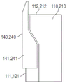
图1a是根据本发明一个实施方案的电子蒸汽发生装置的前视图;Figure 1a is a front view of an electronic vapor generating device according to one embodiment of the present invention;
图1b是图1a中所示的电子蒸汽发生装置的侧视图;Figure 1b is a side view of the electronic vapor generator shown in Figure 1a;
图1c是图1a中所示的电子蒸汽发生装置的俯视图;Figure 1c is a top view of the electronic vapor generating device shown in Figure 1a;
图2a是图1中所示的电子蒸汽发生装置的第一实施方案的沿图1b的线A-A截取的示意性截面图;Figure 2a is a schematic cross-sectional view taken along line A-A of Figure 1b of the first embodiment of the electronic vapor generating device shown in Figure 1;
图2b是图1中所示的电子蒸汽发生装置的第二实施方案的沿图1b的线A-A截取的示意性截面图;Fig. 2b is a schematic cross-sectional view taken along line A-A of Fig. 1b of the second embodiment of the electronic vapor generating device shown in Fig. 1;
图3a是通过具有布置成升高构型的导管的盒体的截面图;Figure 3a is a cross-sectional view through a cassette having conduits arranged in a raised configuration;
图3b是通过具有布置成下降构型的导管的盒体的截面图;Figure 3b is a cross-sectional view through a cassette having a conduit arranged in a descending configuration;
图4a是布置成收起构型的图1所示电子蒸汽发生装置的前视图;Figure 4a is a front view of the electronic vapor generating device of Figure 1 arranged in a stowed configuration;
图4b是布置成操作构型的图1中所示的电子蒸汽发生装置的前视图;和Figure 4b is a front view of the electronic vapor generating device shown in Figure 1 arranged in an operational configuration; and
图4c是布置成释放构型的图1中所示的电子蒸汽发生装置的前视图。Figure 4c is a front view of the electronic vapor generating device shown in Figure 1 arranged in a release configuration.
具体实施方式Detailed ways
参考附图的图1和图2a,示出了根据本发明的第一实施方案的电子蒸汽发生装置100。该装置包括壳体110,其可以由刚性塑料材料或金属例如铝形成。壳体110为几个装置部件提供了一个保护壳,并在其中限定了一个腔室120,用于接受一个可更换的盒体130,该盒体130布置成保持产生蒸汽的液体。Referring to Figures 1 and 2a of the accompanying drawings, there is shown an
装置100包括吸嘴140,吸嘴140在所示实施方案中沿着壳体110的侧向边缘111可滑动地连接。然而,在未示出的可供选择实施方案中,吸嘴可枢转地或可旋转地连接于壳体110。参照图1和图2a中所示的实施方案,吸嘴140沿壳体110的纵向延伸,并且可沿着侧向边缘111在基本平行于装置100的纵向轴线的方向上滑动。吸嘴140可在收起构型和操作构型之间重新配置,并且包括外壳141,外壳141可以由类似于壳体110的硬质塑料材料或者金属例如铝形成。吸嘴外壳141成形为与壳体110的形状符合,使得当吸嘴部件140被布置成收起构型时,吸嘴外壳141和壳体共同限定大致长方体形状。当配置为操作构型时,吸嘴140的远端布置成远离壳体110延伸并且布置在壳体的上部区域112上方。The
参考附图的图3a和图3b,示出了根据本发明的一个实施方案的提供用于电子蒸汽发生装置例如上述的装置100(或者如下所述第二实施方案的装置120)的液体的盒体130。盒体130包括由盒体130的外壁132限定的容器131,用于保持产生蒸汽的液体。盒体130可以通过设置在盒体130的上壁部分132a中的可拆卸的安全帽130a来填充。安全帽130a可以被布置成例如拧入/旋出上壁部分132a,并且包括设置在安全帽130a的下侧的密封件130b,用于提供与上壁部分132a的密封连接。盒体130进一步包括设置在容器131内的雾化器150,用于雾化液体以产生蒸汽。雾化器150包括基本上圆柱形的横截面外壁,并且从盒体130的基部132b延伸。雾化器150的上部与导管133流体连通,导管133从雾化器150基本上沿着雾化器150轴线向上延伸并且包括开放的远端,该开放的远端经由围绕导管133延伸的套环密封件135滑动地且密封地连接在盒体130的壁132的上壁部分132a'中形成的端口134内。导管133被布置成将在雾化器150内产生的蒸汽从容器131传送出并进入吸嘴140以供使用者吸入。Referring to Figures 3a and 3b of the accompanying drawings, there is shown a cartridge providing liquid for use in an electronic vapor generating device such as the
在所示实施方案中,盒体130包括大致长方体形状,然而,上壁部分132a在盒体的上壁部分132a'上方竖直移位,使得上壁包括阶梯式轮廓。In the illustrated embodiment, the
雾化器150包括形成在其外壁中的多个通道151,其围绕外壁成角度地隔开,用于将来自容器131内的液体连通到雾化器150中。然而,盒体130在蒸汽发生装置100(或蒸汽发生装置200-见下文)内的初始使用之前,希望防止液体进入雾化器150。优选将液体保持在容器131内的密封环境中以保持液体的完整性,例如在盒体130保持存储期间。因此,盒体130进一步包括套筒136,套筒136布置成遮蔽雾化器150的至少一部分。套筒136在其上部区域处连接于导管133并且包括形成在其中的多个孔136a并且围绕套筒136成角度地分开。The
在盒体130的初始使用之前,导管133的远端经由端口134从容器131中伸出,并且套筒136相对于雾化器150以升高构型设置,使得形成在雾化器150内部的通道151被套筒136封闭。在这种构型中,套筒136防止液体进入雾化器150,从而有效地将液体密封在容器131内。当使用者希望将盒体130插入到蒸汽发生装置100内,使用者首先按压导管133的远端以使导管133进入容器131。同时,这导致套筒136沿着雾化器150的外侧滑落。当导管133被完全插入时,形成在盒体壁132上的倒钩137(如附图的图3b所示)被布置为快速地定位在导管133的远端内形成的孔137a内以锁定导管133从而套筒136处于降低构型,其中套筒136中的孔136a与雾化器150内的通道151对齐。在这种构型中,液体可以通过对准的孔136a和通道151进入雾化器150进行雾化。Prior to initial use of the
盒体130进一步包括在盒体130的基部处形成的对接站138。对接站138设置在雾化器150的下侧,并且包括内部容积,该内部容积经由O型圈密封件和套环密封件139a、139b与容器131的内部密封。对接站包括多个电接触器138a,其提供进入盒体130的电路径,特别是雾化器150的电连接(未示出),从而电力可被供应到雾化器150。对接站138进一步包括定位构件例如磁体138b,磁体138b被布置成与设置在腔室120内的磁体(未示出)相互作用,以便将盒体130在腔室120中适当地对准并定位。
吸嘴140经由连接管142与导管133流体连接,所述连接管142在其近端处刚性地连接于在使用中设置在吸嘴140的上部区域处的开口143。连接管142的远端以在导管133的内部滑动和密封接触的方式延伸,使得在雾化器150内产生的蒸汽能够经由导管133和连接管142从吸嘴140流出。The
雾化器150通过电源160例如设置在外壳110内的可再充电电池装置,经由致动器例如同样设置在外壳110内的开关170供电。开关170包括可重构臂171,其可旋转,以打开和闭合开关170,从而使雾化器150与电池装置160电耦合和解耦(即隔离)。可重构臂171的旋转通过吸嘴140沿着壳体110的侧向边缘111移动来进行,使得在收起构型中,开关170被设置成占据打开状态,在该打开状态下防止雾化器150的操作并且装置“关闭”。然而,随着吸嘴140重新配置为操作构型,开关170被布置为重新配置成闭合状态以将电池装置160与雾化器150电耦合,并且因此将装置置于“开启”状态。The
吸嘴140经由滑动机构(未示出)可滑动地连接于装置壳体110。该机构包括偏置装置(未示出),该偏置装置被布置成以收起和操作构型偏置吸嘴140,使得用户在重新配置吸嘴140时需要克服阈值力。吸嘴140的偏置可以由例如一个或多个弹簧(未示出)来提供,由此在吸嘴部件140采用收起或操作构型时,在随后恢复到其自然长度之前,重新配置吸嘴部件140需要一个或多个弹簧(未示出)压缩。可替代地或另外,偏置可以由一个或多个磁体(未示出)提供,由此,吸嘴140的重新配置引起由磁体(未示出)之间的磁排斥产生的力的逐渐增加,直到阈值位置。然而,随着吸嘴140移动超过阈值位置,磁排斥力被布置成将吸嘴140偏置到所需的构型。The
在一个实施方案中,吸嘴140可进一步重新配置为释放构型,其通过使吸嘴140滑动超过操作构型而实现。在这种构型中,吸嘴140可以与壳体110的侧向边缘111分离,以使得盒体130能够被更换/插入到腔室120内。吸嘴140然后可以进一步与壳体110连接并且根据需要被重新配置成操作或者收起构型。In one embodiment, the
蒸汽发生装置100进一步包括印刷电路板180,该印刷电路板180包括定时器181和处理器182,用于控制雾化器150的操作并且用于监视雾化器150的激活时间,即处于操作构型中的吸嘴140所占用的时间。装置100进一步包括设置在壳体110内的表盘183,用户可以访问表盘183。表盘183与电位计184耦合,电位计184被设置为控制由电池装置160在雾化器150上施加的电压。已发现,由雾化器150产生的蒸汽的量与在雾化器150上施加的电压有关,并且因此,用户可以通过改变电压来调整产生的蒸汽的量以适合他们的偏好。还可以设想的是,该装置可以包括用于监测雾化器150的温度的温度感测装置(未示出)。已经发现,雾化器150可以在长时间的操作期间变热,并且温度感测装置被设置为根据感测到的温度向开关170输出信号,以使开关170从关闭状态重新配置成打开状态。例如,在温度感测装置(未示出)检测到高于阈值温度(例如可以预先设定)的温度的情况下,温度感测装置(未示出)被布置为向开关170输出信号以使开关170打开,从而断开对雾化器150的供电。或者,温度感测装置可以被布置成,如果感测到的温度达到预先定义的阈值,向电位计输出信号以限制或减低雾化器两端施加的电压,从而避免了导致开关打开的要求。The
装置100还包括设置在壳体的侧壁113中的电气端口185,例如USB端口,用于将装置100与外部电源(未示出)例如用于给电池充电的主电源装置160电连接。The
参考附图的图1和图2b,示出了根据本发明的第二实施方案的电子蒸汽发生装置200。第二实施方案的装置200与第一实施方案的装置100基本相同,因此类似的特征已经使用相同的附图标记而被增加了100。然而,第二实施方案的装置200包括设置在电池装置260和雾化器250之间的电气路径中的第一和第二开关组件290、291。根据第二实施方案的装置200,吸嘴240在收起和操作构型之间的重新配置被布置成,将装置的操作状态从“关”状态重新配置到“待机”状态,而不是“开启”状态。第一开关组件290包括布置在装置200的基部附近的开关290a(例如簧片开关)以及布置在吸嘴240的近端处的磁体290b。磁体290b布置成根据吸嘴240的移动而移动,并且当吸嘴240布置成收起构型时,磁体290b从簧片开关290a移位。然而,当吸嘴240被配置为操作构型时,磁体290b被布置为邻近簧片开关290a对齐,并且在该构型中,磁体290b和开关290a之间的磁相互作用导致开关290a从打开构型重新配置到关闭构型,以将装置200置于待机状态。Referring to Figures 1 and 2b of the accompanying drawings, there is shown an
第二开关组件291包括压力传感器291a和另外的开关(未示出)。压力传感器291a布置成检测与吸嘴240流体连接的子室291b内的压力。当使用者在吸嘴240上吸入时,吸入作为子室291b内的减压被压力传感器291a检测到,并且该检测作为信号被传送到另外的开关(未示出),以使得另外的开关从打开状态重新配置到关闭状态,并且因此将电池装置260与雾化器250电耦合以产生蒸汽。在这方面,在装置200处于待机状态的情况下,仅当使用者在吸嘴240上吸入时才产生蒸汽。The
参考附图的图4,在使用第一或第二实施方案的装置100、200时,吸嘴140、240被布置成释放构型,使得吸嘴140、240可以与壳体110、210分开以使填充有液体的盒体130、230能够插入壳体110、210内的腔室120、220内。接着,吸嘴140、240可与壳体110、210连接,从而雾化器150,250与容器130、230流体连通和吸嘴140、240然后被重新配置为例如用于储存的收起构型。Referring to Figure 4 of the drawings, when using the
例如,当使用者希望使用第一实施方案的装置100时,首先沿着壳体110的横向边缘111移动吸嘴140,以将吸嘴140重新配置成操作构型,从而接通装置。根据第一实施方案的装置,该移动使得吸嘴140的远端延伸到壳体110的上部区域112以上,同时,开关170被重新配置为第二状态以将雾化器150与电池装置160导电连接。在操作构型中,雾化器150布置成从容器131抽取液体并使液体雾化以形成蒸汽,蒸汽随后可通过使用者在吸嘴140的远端处吸吮而经由开口143从吸嘴140被吸出。一旦已经取得期望的吸入次数,吸嘴140然后可以被重新配置为收起构型,于是开关170返回到打开状态并且因此将雾化器150与电池装置160电隔离,从而关闭该装置。For example, when a user wishes to use the
在将吸嘴140重新配置成操作构型时,处理器182被配置为触发定时器181以开始计时。处理器182随后监测吸嘴140保持在操作构型中的时间,并且在吸嘴140保持在操作构型中的时间多于预定时间(例如5-10秒的时间)的情况下,那么处理器182被布置成将雾化器150与电池装置160电隔离。可以设想的是,如果在例如用户口袋或包(未示出)里时吸嘴无意中重新配置为操作构型,则该安全切断将防止雾化器150的连续的意外操作。此外,应该理解的是,如果使用者希望进行超过预定的时间的持久的一系列吸入持续时间,则需要使用者将吸嘴140重新配置成收起构型,然后返回到操作构型,以再激活雾化器150。Upon reconfiguring the
可供选择地,在使用第二实施方案的装置期间,吸嘴240的重新配置可以代之以使装置200处于待机状态,由此仅当使用者在吸嘴240上吸入时才产生蒸汽。第二实施方案的装置200因此避免了例如在吸入之间使用者将吸嘴240在操作状态和收起状态之间重新配置的需要。Alternatively, during use of the device of the second embodiment, reconfiguration of the
当需要更换盒体130、230时,那么吸嘴140、240被重新配置为释放构型,于是吸嘴140、240可从壳体110、210脱开以允许盒体130、230从其中移除。随后可以插入替换盒体130、230,并且吸嘴140、240与壳体110、210重新连接并且重新配置成例如操作或收起构型。When the
因此,从上述内容显而易见的是,上述装置提供了产生蒸汽的更紧凑的布置。Thus, it is apparent from the above that the above-described device provides a more compact arrangement for generating steam.
Claims (15)
Applications Claiming Priority (3)
| Application Number | Priority Date | Filing Date | Title |
|---|---|---|---|
| GBGB1509590.4A GB201509590D0 (en) | 2015-06-03 | 2015-06-03 | Electronic vapour generating device |
| GB1509590.4 | 2015-06-03 | ||
| PCT/GB2016/051586 WO2016193705A2 (en) | 2015-06-03 | 2016-05-31 | Electronic vapour generating device |
Publications (2)
| Publication Number | Publication Date |
|---|---|
| CN107683095A CN107683095A (en) | 2018-02-09 |
| CN107683095B true CN107683095B (en) | 2020-11-27 |
Family
ID=53677687
Family Applications (1)
| Application Number | Title | Priority Date | Filing Date |
|---|---|---|---|
| CN201680031865.1A Expired - Fee Related CN107683095B (en) | 2015-06-03 | 2016-05-31 | Electronic steam generator |
Country Status (6)
| Country | Link |
|---|---|
| US (1) | US10874144B2 (en) |
| EP (1) | EP3302110A2 (en) |
| CN (1) | CN107683095B (en) |
| CA (1) | CA2987163A1 (en) |
| GB (2) | GB201509590D0 (en) |
| WO (1) | WO2016193705A2 (en) |
Families Citing this family (29)
| Publication number | Priority date | Publication date | Assignee | Title |
|---|---|---|---|---|
| US20160345631A1 (en) | 2005-07-19 | 2016-12-01 | James Monsees | Portable devices for generating an inhalable vapor |
| US10279934B2 (en) | 2013-03-15 | 2019-05-07 | Juul Labs, Inc. | Fillable vaporizer cartridge and method of filling |
| PT3508080T (en) | 2013-12-23 | 2021-03-02 | Juul Labs Int Inc | VAPORIZATION DEVICE SYSTEMS AND METHODS |
| US10058129B2 (en) | 2013-12-23 | 2018-08-28 | Juul Labs, Inc. | Vaporization device systems and methods |
| US10159282B2 (en) | 2013-12-23 | 2018-12-25 | Juul Labs, Inc. | Cartridge for use with a vaporizer device |
| USD825102S1 (en) | 2016-07-28 | 2018-08-07 | Juul Labs, Inc. | Vaporizer device with cartridge |
| USD842536S1 (en) | 2016-07-28 | 2019-03-05 | Juul Labs, Inc. | Vaporizer cartridge |
| US10076139B2 (en) | 2013-12-23 | 2018-09-18 | Juul Labs, Inc. | Vaporizer apparatus |
| US20160366947A1 (en) | 2013-12-23 | 2016-12-22 | James Monsees | Vaporizer apparatus |
| CN112155255B (en) | 2014-12-05 | 2025-10-28 | 尤尔实验室有限公司 | Corrected dose control |
| WO2017102686A1 (en) * | 2015-12-18 | 2017-06-22 | Jt International S.A. | Inhaler device and method of operating same |
| SG11201806801VA (en) | 2016-02-11 | 2018-09-27 | Juul Labs Inc | Securely attaching cartridges for vaporizer devices |
| US10405582B2 (en) | 2016-03-10 | 2019-09-10 | Pax Labs, Inc. | Vaporization device with lip sensing |
| USD849996S1 (en) | 2016-06-16 | 2019-05-28 | Pax Labs, Inc. | Vaporizer cartridge |
| USD851830S1 (en) | 2016-06-23 | 2019-06-18 | Pax Labs, Inc. | Combined vaporizer tamp and pick tool |
| USD836541S1 (en) | 2016-06-23 | 2018-12-25 | Pax Labs, Inc. | Charging device |
| US11744282B2 (en) * | 2016-06-27 | 2023-09-05 | China Tobacco Hunan Industrial Co., Ltd. | Electronic cigarette |
| WO2018102696A1 (en) | 2016-12-02 | 2018-06-07 | Vmr Products Llc | Vaporizer |
| US10701976B2 (en) | 2016-12-12 | 2020-07-07 | VMR Products, LLC | Vaporizer cartridge |
| USD887632S1 (en) | 2017-09-14 | 2020-06-16 | Pax Labs, Inc. | Vaporizer cartridge |
| CN110403241B (en) * | 2018-04-28 | 2021-02-23 | 深圳御烟实业有限公司 | Aerosol-generating device and system |
| US20210187211A1 (en) * | 2018-05-08 | 2021-06-24 | Omega Life Science Ltd. | Nebulizers, nebulizer cartridges and uses thereof |
| JP7411654B2 (en) | 2018-11-05 | 2024-01-11 | ジュール・ラブズ・インコーポレイテッド | Cartridges for vaporizer devices |
| CA185871S (en) | 2019-01-24 | 2020-07-14 | Vespyr Inc | Smoking pipe |
| CN109805458B (en) * | 2019-03-29 | 2024-11-19 | 深圳市你我网络科技有限公司 | Atomizer and electronic cigarette |
| GB201904844D0 (en) | 2019-04-05 | 2019-05-22 | Nicoventures Trading Ltd | Aerosol generating system |
| USD866853S1 (en) * | 2019-04-22 | 2019-11-12 | Tma Labs Llc | Vaporizer |
| CA3042820A1 (en) | 2019-05-09 | 2020-11-09 | Cory D. Larsen | Water pipe with lid that covers the bowl and mouthpiece, and related methods of assembly and use |
| CN111990699B (en) * | 2020-09-29 | 2025-10-17 | 重庆中烟工业有限责任公司 | Electronic smoking set capable of automatically rotating |
Family Cites Families (12)
| Publication number | Priority date | Publication date | Assignee | Title |
|---|---|---|---|---|
| US6196218B1 (en) * | 1999-02-24 | 2001-03-06 | Ponwell Enterprises Ltd | Piezo inhaler |
| US20060102175A1 (en) * | 2004-11-18 | 2006-05-18 | Nelson Stephen G | Inhaler |
| US7186958B1 (en) * | 2005-09-01 | 2007-03-06 | Zhao Wei, Llc | Inhaler |
| WO2012114322A1 (en) * | 2011-02-24 | 2012-08-30 | Oglesby & Butler Research & Development Limited | A vaporising device |
| US20120255546A1 (en) * | 2011-04-11 | 2012-10-11 | Visionary Road | Portable vaporizer |
| CN204275207U (en) * | 2011-08-16 | 2015-04-22 | Pax实验室公司 | Devices for generating inhalable aerosols |
| WO2014066730A1 (en) * | 2012-10-25 | 2014-05-01 | Lbs Imports, Llc. | Electronic cigarette |
| GB201413028D0 (en) * | 2014-02-28 | 2014-09-03 | Beyond Twenty Ltd | Beyond 5 |
| CN203860454U (en) * | 2014-04-21 | 2014-10-08 | 申敏良 | Airflow adjusting assembly for atomizer of electronic cigarette |
| CN203986121U (en) | 2014-07-16 | 2014-12-10 | 深圳市艾维普思科技有限公司 | A kind of electronic cigarette of adjustable oil inlet quantity |
| WO2016026105A1 (en) * | 2014-08-20 | 2016-02-25 | 深圳市康尔科技有限公司 | Switch mechanism of electronic cigarette |
| CN104605482A (en) * | 2015-01-05 | 2015-05-13 | 深圳市合元科技有限公司 | Replaceable atomization unit and atomizer and electronic cigarette including the same |
-
2015
- 2015-06-03 GB GBGB1509590.4A patent/GB201509590D0/en not_active Ceased
-
2016
- 2016-05-31 CN CN201680031865.1A patent/CN107683095B/en not_active Expired - Fee Related
- 2016-05-31 CA CA2987163A patent/CA2987163A1/en not_active Abandoned
- 2016-05-31 EP EP16736544.4A patent/EP3302110A2/en not_active Withdrawn
- 2016-05-31 WO PCT/GB2016/051586 patent/WO2016193705A2/en not_active Ceased
- 2016-05-31 US US15/578,856 patent/US10874144B2/en not_active Expired - Fee Related
- 2016-05-31 GB GB1609505.1A patent/GB2540259B/en not_active Expired - Fee Related
Also Published As
| Publication number | Publication date |
|---|---|
| CA2987163A1 (en) | 2016-12-08 |
| GB201609505D0 (en) | 2016-07-13 |
| CN107683095A (en) | 2018-02-09 |
| US10874144B2 (en) | 2020-12-29 |
| US20180295883A1 (en) | 2018-10-18 |
| EP3302110A2 (en) | 2018-04-11 |
| GB2540259B (en) | 2021-07-07 |
| WO2016193705A3 (en) | 2017-01-12 |
| GB201509590D0 (en) | 2015-07-15 |
| WO2016193705A2 (en) | 2016-12-08 |
| GB2540259A (en) | 2017-01-11 |
Similar Documents
| Publication | Publication Date | Title |
|---|---|---|
| CN107683095A (en) | Electronic steam generator | |
| JP7311085B2 (en) | electronic aerosol delivery system | |
| JP7019628B2 (en) | Electronic inhaler | |
| JP6012741B2 (en) | Aerosol generator | |
| EP3289897A1 (en) | Atomizer and electronic cigarette having same | |
| CN110709125B (en) | Aerosol generating system with replaceable atomizer | |
| US20160366937A1 (en) | Electronic cigarette | |
| CN104023775A (en) | Portable electronic vapor-producing device and method | |
| KR20180100555A (en) | Water pipe | |
| CN111278310B (en) | Mechanism for hatch of electronic aerosol provision device | |
| JP2011519641A (en) | Aerosol dispensing device | |
| EP4069010B1 (en) | Cartridge insertion systems for aerosol-generating devices | |
| TW202021489A (en) | Vapour generating device | |
| CN109805458B (en) | Atomizer and electronic cigarette | |
| WO2018023334A1 (en) | Electronic cigarette and atomizer thereof | |
| CN110891438B (en) | Aerosol generating device | |
| US20240196983A1 (en) | Liquid Jet Inhalation Device | |
| CN204466902U (en) | Inhalator and atomizing component thereof | |
| KR20160001725U (en) | Electronic Cgarette Having Preventing flowing-backward | |
| KR102768911B1 (en) | Mountable liquid module and aerosol generating device including same | |
| KR20240055336A (en) | Aerosol generator | |
| CN106028858B (en) | Electronic cigarette | |
| GB2574814A (en) | A smoking apparatus | |
| HK40007717A (en) | Electronic inhalation device |
Legal Events
| Date | Code | Title | Description |
|---|---|---|---|
| PB01 | Publication | ||
| PB01 | Publication | ||
| SE01 | Entry into force of request for substantive examination | ||
| SE01 | Entry into force of request for substantive examination | ||
| GR01 | Patent grant | ||
| GR01 | Patent grant | ||
| CF01 | Termination of patent right due to non-payment of annual fee |
Granted publication date: 20201127 |
|
| CF01 | Termination of patent right due to non-payment of annual fee |