CN1077367C - A cellular/satellite communication system with improved frequency reuse - Google Patents
A cellular/satellite communication system with improved frequency reuse Download PDFInfo
- Publication number
- CN1077367C CN1077367C CN95190144A CN95190144A CN1077367C CN 1077367 C CN1077367 C CN 1077367C CN 95190144 A CN95190144 A CN 95190144A CN 95190144 A CN95190144 A CN 95190144A CN 1077367 C CN1077367 C CN 1077367C
- Authority
- CN
- China
- Prior art keywords
- signals
- signal
- channel
- matrix
- frequency
- Prior art date
- Legal status (The legal status is an assumption and is not a legal conclusion. Google has not performed a legal analysis and makes no representation as to the accuracy of the status listed.)
- Expired - Lifetime
Links
Images


















Classifications
-
- H—ELECTRICITY
- H04—ELECTRIC COMMUNICATION TECHNIQUE
- H04W—WIRELESS COMMUNICATION NETWORKS
- H04W16/00—Network planning, e.g. coverage or traffic planning tools; Network deployment, e.g. resource partitioning or cells structures
- H04W16/02—Resource partitioning among network components, e.g. reuse partitioning
-
- H—ELECTRICITY
- H01—ELECTRIC ELEMENTS
- H01Q—ANTENNAS, i.e. RADIO AERIALS
- H01Q1/00—Details of, or arrangements associated with, antennas
- H01Q1/12—Supports; Mounting means
- H01Q1/22—Supports; Mounting means by structural association with other equipment or articles
- H01Q1/24—Supports; Mounting means by structural association with other equipment or articles with receiving set
- H01Q1/241—Supports; Mounting means by structural association with other equipment or articles with receiving set used in mobile communications, e.g. GSM
- H01Q1/246—Supports; Mounting means by structural association with other equipment or articles with receiving set used in mobile communications, e.g. GSM specially adapted for base stations
-
- H—ELECTRICITY
- H01—ELECTRIC ELEMENTS
- H01Q—ANTENNAS, i.e. RADIO AERIALS
- H01Q1/00—Details of, or arrangements associated with, antennas
- H01Q1/27—Adaptation for use in or on movable bodies
- H01Q1/28—Adaptation for use in or on aircraft, missiles, satellites, or balloons
- H01Q1/288—Satellite antennas
-
- H—ELECTRICITY
- H01—ELECTRIC ELEMENTS
- H01Q—ANTENNAS, i.e. RADIO AERIALS
- H01Q21/00—Antenna arrays or systems
- H01Q21/06—Arrays of individually energised antenna units similarly polarised and spaced apart
- H01Q21/08—Arrays of individually energised antenna units similarly polarised and spaced apart the units being spaced along or adjacent to a rectilinear path
-
- H—ELECTRICITY
- H01—ELECTRIC ELEMENTS
- H01Q—ANTENNAS, i.e. RADIO AERIALS
- H01Q21/00—Antenna arrays or systems
- H01Q21/28—Combinations of substantially independent non-interacting antenna units or systems
-
- H—ELECTRICITY
- H01—ELECTRIC ELEMENTS
- H01Q—ANTENNAS, i.e. RADIO AERIALS
- H01Q25/00—Antennas or antenna systems providing at least two radiating patterns
-
- H—ELECTRICITY
- H01—ELECTRIC ELEMENTS
- H01Q—ANTENNAS, i.e. RADIO AERIALS
- H01Q25/00—Antennas or antenna systems providing at least two radiating patterns
- H01Q25/007—Antennas or antenna systems providing at least two radiating patterns using two or more primary active elements in the focal region of a focusing device
-
- H—ELECTRICITY
- H04—ELECTRIC COMMUNICATION TECHNIQUE
- H04B—TRANSMISSION
- H04B7/00—Radio transmission systems, i.e. using radiation field
- H04B7/02—Diversity systems; Multi-antenna system, i.e. transmission or reception using multiple antennas
- H04B7/04—Diversity systems; Multi-antenna system, i.e. transmission or reception using multiple antennas using two or more spaced independent antennas
- H04B7/08—Diversity systems; Multi-antenna system, i.e. transmission or reception using multiple antennas using two or more spaced independent antennas at the receiving station
- H04B7/0837—Diversity systems; Multi-antenna system, i.e. transmission or reception using multiple antennas using two or more spaced independent antennas at the receiving station using pre-detection combining
- H04B7/0842—Weighted combining
- H04B7/0848—Joint weighting
- H04B7/0851—Joint weighting using training sequences or error signal
-
- H—ELECTRICITY
- H04—ELECTRIC COMMUNICATION TECHNIQUE
- H04B—TRANSMISSION
- H04B7/00—Radio transmission systems, i.e. using radiation field
- H04B7/02—Diversity systems; Multi-antenna system, i.e. transmission or reception using multiple antennas
- H04B7/10—Polarisation diversity; Directional diversity
-
- H—ELECTRICITY
- H04—ELECTRIC COMMUNICATION TECHNIQUE
- H04B—TRANSMISSION
- H04B7/00—Radio transmission systems, i.e. using radiation field
- H04B7/14—Relay systems
- H04B7/15—Active relay systems
- H04B7/185—Space-based or airborne stations; Stations for satellite systems
- H04B7/1851—Systems using a satellite or space-based relay
- H04B7/18513—Transmission in a satellite or space-based system
-
- H—ELECTRICITY
- H04—ELECTRIC COMMUNICATION TECHNIQUE
- H04B—TRANSMISSION
- H04B7/00—Radio transmission systems, i.e. using radiation field
- H04B7/14—Relay systems
- H04B7/15—Active relay systems
- H04B7/185—Space-based or airborne stations; Stations for satellite systems
- H04B7/1851—Systems using a satellite or space-based relay
- H04B7/18515—Transmission equipment in satellites or space-based relays
-
- H—ELECTRICITY
- H04—ELECTRIC COMMUNICATION TECHNIQUE
- H04B—TRANSMISSION
- H04B7/00—Radio transmission systems, i.e. using radiation field
- H04B7/14—Relay systems
- H04B7/15—Active relay systems
- H04B7/185—Space-based or airborne stations; Stations for satellite systems
- H04B7/1853—Satellite systems for providing telephony service to a mobile station, i.e. mobile satellite service
- H04B7/18532—Arrangements for managing transmission, i.e. for transporting data or a signalling message
-
- H—ELECTRICITY
- H04—ELECTRIC COMMUNICATION TECHNIQUE
- H04B—TRANSMISSION
- H04B7/00—Radio transmission systems, i.e. using radiation field
- H04B7/14—Relay systems
- H04B7/15—Active relay systems
- H04B7/185—Space-based or airborne stations; Stations for satellite systems
- H04B7/1853—Satellite systems for providing telephony service to a mobile station, i.e. mobile satellite service
- H04B7/18567—Arrangements for providing additional services to the basic mobile satellite telephony service
-
- H—ELECTRICITY
- H04—ELECTRIC COMMUNICATION TECHNIQUE
- H04B—TRANSMISSION
- H04B7/00—Radio transmission systems, i.e. using radiation field
- H04B7/14—Relay systems
- H04B7/15—Active relay systems
- H04B7/204—Multiple access
- H04B7/2041—Spot beam multiple access
-
- H—ELECTRICITY
- H04—ELECTRIC COMMUNICATION TECHNIQUE
- H04L—TRANSMISSION OF DIGITAL INFORMATION, e.g. TELEGRAPHIC COMMUNICATION
- H04L25/00—Baseband systems
- H04L25/02—Details ; arrangements for supplying electrical power along data transmission lines
- H04L25/0202—Channel estimation
- H04L25/0204—Channel estimation of multiple channels
-
- H—ELECTRICITY
- H04—ELECTRIC COMMUNICATION TECHNIQUE
- H04L—TRANSMISSION OF DIGITAL INFORMATION, e.g. TELEGRAPHIC COMMUNICATION
- H04L25/00—Baseband systems
- H04L25/02—Details ; arrangements for supplying electrical power along data transmission lines
- H04L25/0202—Channel estimation
- H04L25/021—Estimation of channel covariance
-
- H—ELECTRICITY
- H04—ELECTRIC COMMUNICATION TECHNIQUE
- H04L—TRANSMISSION OF DIGITAL INFORMATION, e.g. TELEGRAPHIC COMMUNICATION
- H04L25/00—Baseband systems
- H04L25/02—Details ; arrangements for supplying electrical power along data transmission lines
- H04L25/03—Shaping networks in transmitter or receiver, e.g. adaptive shaping networks
- H04L25/03006—Arrangements for removing intersymbol interference
- H04L25/03178—Arrangements involving sequence estimation techniques
- H04L25/03331—Arrangements for the joint estimation of multiple sequences
-
- H—ELECTRICITY
- H04—ELECTRIC COMMUNICATION TECHNIQUE
- H04W—WIRELESS COMMUNICATION NETWORKS
- H04W84/00—Network topologies
- H04W84/02—Hierarchically pre-organised networks, e.g. paging networks, cellular networks, WLAN [Wireless Local Area Network] or WLL [Wireless Local Loop]
- H04W84/022—One-way selective calling networks, e.g. wide area paging
- H04W84/025—One-way selective calling networks, e.g. wide area paging with acknowledge back capability
-
- H—ELECTRICITY
- H04—ELECTRIC COMMUNICATION TECHNIQUE
- H04B—TRANSMISSION
- H04B7/00—Radio transmission systems, i.e. using radiation field
- H04B7/02—Diversity systems; Multi-antenna system, i.e. transmission or reception using multiple antennas
- H04B7/04—Diversity systems; Multi-antenna system, i.e. transmission or reception using multiple antennas using two or more spaced independent antennas
- H04B7/08—Diversity systems; Multi-antenna system, i.e. transmission or reception using multiple antennas using two or more spaced independent antennas at the receiving station
- H04B7/0837—Diversity systems; Multi-antenna system, i.e. transmission or reception using multiple antennas using two or more spaced independent antennas at the receiving station using pre-detection combining
-
- H—ELECTRICITY
- H04—ELECTRIC COMMUNICATION TECHNIQUE
- H04B—TRANSMISSION
- H04B7/00—Radio transmission systems, i.e. using radiation field
- H04B7/14—Relay systems
- H04B7/15—Active relay systems
- H04B7/204—Multiple access
- H04B7/2046—SS-TDMA, TDMA satellite switching
-
- H—ELECTRICITY
- H04—ELECTRIC COMMUNICATION TECHNIQUE
- H04L—TRANSMISSION OF DIGITAL INFORMATION, e.g. TELEGRAPHIC COMMUNICATION
- H04L1/00—Arrangements for detecting or preventing errors in the information received
- H04L1/004—Arrangements for detecting or preventing errors in the information received by using forward error control
- H04L1/0056—Systems characterized by the type of code used
- H04L1/007—Unequal error protection
-
- H—ELECTRICITY
- H04—ELECTRIC COMMUNICATION TECHNIQUE
- H04L—TRANSMISSION OF DIGITAL INFORMATION, e.g. TELEGRAPHIC COMMUNICATION
- H04L25/00—Baseband systems
- H04L25/02—Details ; arrangements for supplying electrical power along data transmission lines
- H04L25/03—Shaping networks in transmitter or receiver, e.g. adaptive shaping networks
- H04L25/03006—Arrangements for removing intersymbol interference
- H04L25/03178—Arrangements involving sequence estimation techniques
- H04L25/03203—Trellis search techniques
-
- H—ELECTRICITY
- H04—ELECTRIC COMMUNICATION TECHNIQUE
- H04L—TRANSMISSION OF DIGITAL INFORMATION, e.g. TELEGRAPHIC COMMUNICATION
- H04L25/00—Baseband systems
- H04L25/02—Details ; arrangements for supplying electrical power along data transmission lines
- H04L25/03—Shaping networks in transmitter or receiver, e.g. adaptive shaping networks
- H04L25/03006—Arrangements for removing intersymbol interference
- H04L25/03178—Arrangements involving sequence estimation techniques
- H04L25/03248—Arrangements for operating in conjunction with other apparatus
- H04L25/0328—Arrangements for operating in conjunction with other apparatus with interference cancellation circuitry
-
- H—ELECTRICITY
- H04—ELECTRIC COMMUNICATION TECHNIQUE
- H04L—TRANSMISSION OF DIGITAL INFORMATION, e.g. TELEGRAPHIC COMMUNICATION
- H04L25/00—Baseband systems
- H04L25/02—Details ; arrangements for supplying electrical power along data transmission lines
- H04L25/03—Shaping networks in transmitter or receiver, e.g. adaptive shaping networks
- H04L25/03006—Arrangements for removing intersymbol interference
- H04L25/03178—Arrangements involving sequence estimation techniques
- H04L25/03248—Arrangements for operating in conjunction with other apparatus
- H04L25/03299—Arrangements for operating in conjunction with other apparatus with noise-whitening circuitry
-
- H—ELECTRICITY
- H04—ELECTRIC COMMUNICATION TECHNIQUE
- H04W—WIRELESS COMMUNICATION NETWORKS
- H04W16/00—Network planning, e.g. coverage or traffic planning tools; Network deployment, e.g. resource partitioning or cells structures
- H04W16/14—Spectrum sharing arrangements between different networks
-
- H—ELECTRICITY
- H04—ELECTRIC COMMUNICATION TECHNIQUE
- H04W—WIRELESS COMMUNICATION NETWORKS
- H04W74/00—Wireless channel access
- H04W74/08—Non-scheduled access, e.g. ALOHA
-
- H—ELECTRICITY
- H04—ELECTRIC COMMUNICATION TECHNIQUE
- H04W—WIRELESS COMMUNICATION NETWORKS
- H04W84/00—Network topologies
- H04W84/02—Hierarchically pre-organised networks, e.g. paging networks, cellular networks, WLAN [Wireless Local Area Network] or WLL [Wireless Local Loop]
- H04W84/04—Large scale networks; Deep hierarchical networks
- H04W84/042—Public Land Mobile systems, e.g. cellular systems
-
- H—ELECTRICITY
- H04—ELECTRIC COMMUNICATION TECHNIQUE
- H04W—WIRELESS COMMUNICATION NETWORKS
- H04W84/00—Network topologies
- H04W84/02—Hierarchically pre-organised networks, e.g. paging networks, cellular networks, WLAN [Wireless Local Area Network] or WLL [Wireless Local Loop]
- H04W84/04—Large scale networks; Deep hierarchical networks
- H04W84/06—Airborne or Satellite Networks
Landscapes
- Engineering & Computer Science (AREA)
- Computer Networks & Wireless Communication (AREA)
- Signal Processing (AREA)
- Physics & Mathematics (AREA)
- Astronomy & Astrophysics (AREA)
- General Physics & Mathematics (AREA)
- Aviation & Aerospace Engineering (AREA)
- Power Engineering (AREA)
- Remote Sensing (AREA)
- Radio Relay Systems (AREA)
- Mobile Radio Communication Systems (AREA)
- Time-Division Multiplex Systems (AREA)
Abstract
Description
背景:background:
本发明涉及增加容量的无线通信系统。该系统可以包括多个漫游的、移动车载的或手持的电话机,由固定的地面基站或轨道卫星或二者混合的方式为之服务。这样的系统容量按照为业务分配了多少无线频谱以及使用的效率来对大量的用户提供服务。频率使用的效率以每平方公里每兆赫兹同时通话数(erlangs)为单位来衡量。一般来说,频谱的效率可由寻找使可用的带宽复用的方法来提高,而不是试图将多个通话塞入同一带宽内,因为缩小带宽一般会产生在各通话之间增加频段间隔的需要,因而抵消了容量上的增益。所以,较好的方法是为每个通话增加带宽。以便使较近的频率复用成为可能。The present invention relates to increased capacity wireless communication systems. The system may consist of a number of nomadic, mobile vehicular or hand-held telephones served by fixed terrestrial base stations or orbiting satellites or a combination of both. Such system capacity provides services to a large number of users according to how much radio frequency spectrum is allocated for business and the efficiency of use. The efficiency of frequency usage is measured in units of simultaneous calls per megahertz per square kilometer (erlangs). In general, spectral efficiency can be improved by finding ways to reuse the available bandwidth, rather than trying to cram multiple calls into the same bandwidth, since narrowing the bandwidth generally creates the need to increase the frequency band spacing between calls, Thus canceling out the gain in capacity. So, a better approach is to increase the bandwidth for each call. In order to make closer frequency reuse possible.
扩频通信系统(即CDMA系统),用高冗余编码来增加信号带宽,使信号能在其它用户干扰的情况下被读出,提供了较高的频谱效率。使用这样的系统,同一网眼内的多个用户可以在同一频段内共存,频率和时间上都是重迭的。如果可以容忍同一网眼内的同频干扰,一个或多个网眼以外的同频干扰也就可以容忍了,因为距离将减弱干扰的作用,所以所有网眼内的所有频率都可能复用。The spread spectrum communication system (namely CDMA system) uses high redundancy coding to increase the signal bandwidth, so that the signal can be read out under the interference of other users, and provides higher spectral efficiency. Using such a system, multiple users within the same cell can coexist in the same frequency band, overlapping both in frequency and time. If co-channel interference in the same cell can be tolerated, co-channel interference outside one or more cells can also be tolerated, because distance will weaken the effect of interference, so all frequencies in all cells may be reused.
扩频系统容量具有自干扰的限制,因为与所需信号同时接收下来的不需要的信号在同一频率上贡献了一个干扰成分。仅管如此,一些系统,例如卫星通信系统,已经受到自然噪声的限制,因此宽带扩频方法就不一定是增加容量的最好技术。结果就需要在不遭受宽带扩频的自干扰的不利后果的条件下,在每个邻近的蜂窝或区域内复用整个频谱。Spread-spectrum system capacity is limited by self-interference because unwanted signals received at the same time as the desired signal contribute an interference component on the same frequency. Even so, some systems, such as satellite communication systems, are already limited by natural noise, so wideband spread spectrum methods are not necessarily the best technique for increasing capacity. Consequently, there is a need to reuse the entire spectrum in each adjacent cell or region without suffering the adverse consequences of self-interference of wideband spread spectrum.
图1表示了一个典型的使用地面基站的蜂窝电话网络的构成。这张图只是表示了这样的网络,例如网眼不总是如此规则的大小和形状,并且做为一个一般定义的网眼可以描述为一个由特定信号激励的区域。Figure 1 shows the configuration of a typical cellular telephone network using terrestrial base stations. This diagram just represents such a network, eg meshes are not always of such regular size and shape, and as a general definition a mesh can be described as an area excited by a particular signal.
网眼可以从它们的地理中心激励,但一般地由三个网眼组的连接处的公共点来激励,因为地点的房产地价是主要的经济考虑。网眼的中心激励的天线辐射方位图一般在方位角上是全方向的。缩小在垂直平面上的辐射方位图使能量集中于陆地上的电话机,避免能量向天空辐射的浪费也是共同的。当出于经济考虑三个网眼的发射器和天线集中在同一位置时,天线的角度只需激励120度扇区;而且所得的方向增益对网眼远边的双倍距离做了很大的补偿。适当塑造天线形状可以用在每个方向上所需的最大范围提供增益补偿,每一个相对于中心面等分为±60度。因此一个扇面化的天线方位图可以在±60°上减小到-12dB,提供中心扇面增益大约8-9dB,以使该方向上实现最大范围。Meshes can be motivated from their geographic centers, but are generally motivated by a common point at the junction of three mesh groups, since property land values at sites are the primary economic consideration. The antenna radiation pattern excited by the center of the cell is generally omnidirectional in azimuth. It is also common to reduce the radiation pattern on the vertical plane so that the energy is concentrated on the telephone set on the land, and it is also common to avoid the waste of energy radiating to the sky. When the transmitters and antennas of the three cells are concentrated at the same location for economical reasons, the antenna angle only needs to excite a 120-degree sector; and the resulting directional gain greatly compensates for the double distance at the far edge of the cells. Properly shaping the antenna can provide gain compensation with the desired maximum range in each direction, each equally divided by ±60 degrees relative to the center plane. Thus a sectorized antenna pattern can be reduced to -12dB over ±60°, providing a center sector gain of about 8-9dB for maximum range in that direction.
使用中心激励,U.S.AMPS蜂窝移动电话系统不能在环绕给定网眼的21个网眼区域内复用相同的频率。这称做21网眼频率复用方式,其结果是当所有信道同时使用时(一般称为最大负荷)同信道干扰低于所需信号大约18dB。这样一个21网眼复用模式在图2中表示。某个复用模式大小例如3、4、7以及它们的乘积(即9、12、21…)产生了与所需信号相同距离的同信道干扰,并定位在六角形的边缘,由多个等于方位图大小的平方根的网眼所隔开。Using central excitation, the U.S. AMPS cellular mobile telephone system cannot reuse the same frequency within the 21 cell areas surrounding a given cell. This is called 21-cell frequency reuse and results in co-channel interference being about 18dB below the desired signal when all channels are in use at the same time (commonly referred to as maximum load). Such a 21-cell multiplexing pattern is shown in FIG. 2 . A certain multiplexing pattern size such as 3, 4, 7 and their products (i.e. 9, 12, 21...) produces co-channel interference at the same distance from the desired signal and is positioned at the edge of the hexagon by a number equal to The mesh is separated by the square root of the azimuth size.
实际上,激励从三个网眼的邻接处产生。尽管复用模式是一个21网眼模式,它也可描述成7地点,每个有3频率复用的模式环绕着三个120度的扇区。从这种激励方式产生的信号同信道干扰特性,不精确地与从中心激励产生的那些特性相等。(由于天线的方向性,可以看到对于特定信号的干扰主要产生于天线在正对方向上发射的两个其它地点,并且不来自于在共同频率上发射的六个等距离的网眼,类似中心激励的情况)。In fact, the excitation is generated from the adjacency of the three meshes. Although the reuse pattern is a 21-cell pattern, it can also be described as 7 locations, each with 3 frequency reuse patterns surrounding three 120-degree sectors. The co-channel interference characteristics of signals resulting from this excitation are not exactly equal to those resulting from central excitation. (Due to the directivity of the antenna, it can be seen that the interference to a specific signal is mainly generated by the two other locations where the antenna transmits in the direct direction, and does not come from the six equidistant cells transmitting on a common frequency, similar to the central excitation Case).
3扇区、7地点的激励方法一般称为扇面化,它可能给人以错误印象:即由于使用了方向性天线,原来较大的网眼被分成3个较小的网眼或扇区。这种印象却是不准确的,因为从同一个地点用于激励三个网眼的结构仅是经济上的安排,实际上考虑到技术性能比中心激励稍有缺陷,但这种缺陷是很小的。The excitation method of 3 sectors and 7 locations is generally called sectorization, which may give people the wrong impression: that is, due to the use of directional antennas, the original larger mesh is divided into 3 smaller meshes or sectors. This impression is inaccurate, because the structure used to excite three meshes from the same location is only an economic arrangement. In fact, considering the technical performance, it has a slight defect compared to the central excitation, but this defect is very small. .
网眼分割完全是另一个概念,它是通过在地面上更密集地提供基站以得到每平方公里更高的容量的一种方法。在一个已有系统中引入网眼分割时常需要完全修改频率复用方案,因为一般不可能简单地分割一个网眼,例如,分成三个网眼,并三次复用原来的频率。这会使三个新的网眼工作在没有间隔的相同频率上,产生一个问题,即在两个网眼边界上的一个移动电话从两个网眼的相同频率上接收相等强度(但内容不同)的信号。因此,需要使一个网眼分成具有相同频率的扇面,并在每个当中不带上述的干扰问题。Cell segmentation is another concept entirely, and it is a way to get higher capacity per square kilometer by provisioning base stations more densely on the ground. Introducing cell division into an existing system often requires a complete revision of the frequency reuse scheme, since it is generally not possible to simply divide a cell, for example, into three cells, and reuse the original frequency three times. This would cause the three new cells to operate on the same frequency with no spacing, creating a problem where a mobile phone on the border of two cells would receive signals of equal strength (but different content) from the same frequency in both cells . Therefore, it is desirable to divide a cell into sectors having the same frequency without the above-mentioned interference problems within each.
在设计用于车载或手持话机的卫星通信系统时也会产生类似的容量问题。对手持机,不同性能的全向天线实际上是大多数消费者乐意接受的。必须定向到卫星或较大的、较笨重天线的定向天线现在在市场上不受欢迎,所以卫星必须给地面提供足够高的信号强度,以便能与这样的设备进行通信。地面上从卫星接收的信号强度一般用每平方米瓦为单位或以对数尺度每平米dBW为单位进行计量。例如,每平方米-123dBW量级的流密度,在下行链路频率使用2GHz时用于给话音通信提供足够的链路容限以抵抗多径衰落、阳影效应、极化失调等。卫星辐射的总瓦数就等于这个所需的流密度乘以它激励的地理区域的面积。例如,在全美国任意地方提供这样一个话音信道,在9百万平方公里的面积上需要的总辐射功率为:Similar capacity issues arise when designing a satellite communication system for use in vehicles or handsets. For handsets, omnidirectional antennas with different performances are actually acceptable to most consumers. Directional antennas that must be directed to the satellite or larger, bulkier antennas are not popular in the market today, so the satellite must provide a high enough signal strength to the ground to be able to communicate with such a device. Signal strength received from satellites on the ground is typically measured in watts per square meter or dBW per square meter on a logarithmic scale. For example, the current density of -123dBW per square meter is used to provide sufficient link tolerance for voice communication when the downlink frequency is 2GHz to resist multipath fading, sun shadow effect, polarization imbalance, etc. The total wattage radiated by the satellite is equal to this required flux density multiplied by the area of the geographic area it excites. For example, to provide such a voice channel anywhere in the United States, the total radiated power required over an area of 9 million square kilometers is:
10-12.3×9×1012=4.5瓦10 -12.3 × 9 × 10 12 = 4.5 watts
从卫星上来的一个话音信道当然不能提供有用的容量。5千到1万Erlangs是比较合理的为全美国服务的目标。增加容量的一个方法是在其它的频道上也产生4.5瓦特功率,每个频道带一路话音信道;但是,一个4.5千瓦的卫星将是很大而且发射费用昂贵,不是提供10000Erlangs容量的经济的方法。因此更有效的是,使用4.5瓦的卫星RF功率在美国的所有地方产生一个足够流密度的话音信道,想办法允许在不同的地方使用不同的流传输话音,这样就不用更多的功率或频带就能支持很多不同的通话。A voice channel from satellite certainly does not provide useful capacity. 5,000 to 10,000 Erlangs is a reasonable target to serve the entire United States. One way to increase capacity would be to generate 4.5 watts on other channels as well, each with one voice channel; however, a 4.5 kilowatt satellite would be large and expensive to launch, and is not an economical way to provide 10,000 Erlangs of capacity. So it is more efficient to use 4.5 watts of satellite RF power to generate a voice channel of sufficient flux density all over the US, and find a way to allow different streams to be used for voice in different places, so that no more power or frequency band is used It can support many different calls.
卫星在不同方向上不同地调制相同的辐射流密度的能力依赖于由它的天线孔径提供的角分辨率。一个天线(在辐射中)的角分辨率的量级是波长与天线直径之比。使用一个示范性的下行链路频率2GHz(波长15cm),直径1.5米的天线,理论上角分辨率是1/10半径或5.7度的量级,这个量级,例如从10000公里的轨道高度,允许的分辨率在美国覆盖区域内可达到分辨37个不同方向的能力。因此,卫星辐射功率的同一个4.5瓦也支持不只一个,而是37个不同的通话。The ability of a satellite to modulate the same radiant current density differently in different directions depends on the angular resolution provided by its antenna aperture. The angular resolution of an antenna (in radiation) is of the order of the wavelength divided by the diameter of the antenna. Using an exemplary downlink frequency of 2 GHz (
产生37个不同波束的方法如图3中所示。一个抛物面反射镜将从一个带37个不同的馈源的方位图中聚集无线电波能量下达地面。馈源的映像被投射到地面,形成所需的分离的激励区域。不幸的是,使用这种技术存在从一个区域到另一个区域的泄露,并且无论如何两个或三个网眼边界处的一个移动电话从两或三个馈源接收相等的信号。如果这些信号是分别调制的,电话接收到不能辨认的三个通话的混合。因此,传统的系统不能开发使用分辨率来实现的潜在的容量增加。A method of generating 37 different beams is shown in FIG. 3 . A parabolic reflector will focus radio wave energy down to the ground from an azimuthal pattern with 37 different feeds. Images of the feeds are projected onto the ground to form the desired discrete excitation regions. Unfortunately, with this technique there is leakage from one area to another, and in any case a mobile phone at the border of two or three cells receives equal signals from two or three feeds. If these signals were modulated separately, the phone would receive an unrecognizable mix of the three calls. Therefore, conventional systems cannot exploit the potential capacity increase achieved using resolution.
总结 Summarize
在传统的天线通信系统、卫星通信系统以及二者的混合中遇到的这些以及其它的缺陷和困难将按照本发明得到克服。These and other deficiencies and difficulties encountered in conventional antenna communication systems, satellite communication systems, and hybrids of the two are overcome in accordance with the present invention.
按照本发明的一个示范实施例,矩阵处理用来形成多个数据采样流的数值混合。选择矩阵系数,并可周期性地调整,使多个接收器中的每一个实际上不带干扰地接收所需的信号。According to an exemplary embodiment of the present invention, matrix processing is used to form a numerical blend of multiple streams of data samples. The matrix coefficients are selected and adjusted periodically so that each of the multiple receivers receives the desired signal virtually without interference.
按照本发明的另一个示范实施例,信号处理不适于移动电话的移动或新通话的建立以及终止,但是可用确定方法操作,而流量适于使用动态流量信道分配算法的信号处理的确定特性。According to another exemplary embodiment of the present invention, the signal processing is not adapted to the movement of the mobile phone or the establishment and termination of new calls, but can be operated in a deterministic way, while the flow is adapted to the deterministic nature of the signal processing using the dynamic traffic channel allocation algorithm.
附图简单描述A brief description of the drawings
前面所述以及其它的本发明的目的、特性、以及优点通过结合图阅读相关的如下的详细描述之后会得到更好的了解,其中:The foregoing and other objects, features, and advantages of the present invention will be better understood by reading the following detailed description in conjunction with the drawings, wherein:
图1图示了一个传统的基于陆地的蜂窝网;Figure 1 illustrates a conventional land-based cellular network;
图2图示了一个传统的21网眼频率复用方案;Figure 2 illustrates a conventional 21-cell frequency reuse scheme;
图3表示了一个传统的激励地球一个区域的37波束卫星实施方案;Figure 3 shows a conventional 37-beam satellite implementation that excites a region of the Earth;
图4图示了用于描述本项发明特性的一个激励模式。Figure 4 illustrates an excitation scheme used to characterize the present invention.
图5表示了一个3网眼频率复用方案;Figure 5 shows a 3-cell frequency reuse scheme;
图6表示了一个根据本发明的一个示范实施例的卫星-移动通信系统。FIG. 6 shows a satellite-mobile communication system according to an exemplary embodiment of the present invention.
图7图示了一个根据本发明的一个示范实施例的移动台到中心站的转发器。Figure 7 illustrates a mobile station to central station repeater according to an exemplary embodiment of the present invention.
图8(a)图示了一个根据本发明的一个示范实施例的中心站到移动台的卫星转发器。Figure 8(a) illustrates a central station to mobile station satellite transponder according to an exemplary embodiment of the present invention.
图8(b)图示了一个根据本发明的另一个示范实施例的用于功率放大器矩阵的合成网络;Figure 8(b) illustrates a synthesis network for a power amplifier matrix according to another exemplary embodiment of the present invention;
图9表示了一个根据本发明的示范FDMA实施例的一个中心站。Figure 9 shows a central station according to an exemplary FDMA embodiment of the present invention.
图10图示了一个基于本发明的一个示范实施例的相干波束信号的传输;Figure 10 illustrates the transmission of a coherent beam signal based on an exemplary embodiment of the present invention;
图11表示了基于一个示范实施例的,在K波段中心站链路上使用双极化的频谱特性;Figure 11 shows the spectral characteristics of using dual polarization on the K-band central station link based on an exemplary embodiment;
图12是一个框图,图解了基于一个示范实施例的波束信号的相位相干传输。Figure 12 is a block diagram illustrating phase coherent transmission of beam signals according to an exemplary embodiment.
图13是一个框图,图解了基于本发明的另一个示范实施例的波束信号的相位相干传输;13 is a block diagram illustrating phase coherent transmission of beam signals based on another exemplary embodiment of the present invention;
图14图示了2比特复用的I、Q信号到一个K波段载波矢量的映射。Figure 14 illustrates the mapping of 2-bit multiplexed I, Q signals to a K-band carrier vector.
图15是一个框图,图示了相位相干波束信号传输的另一个示范实施例;Figure 15 is a block diagram illustrating another exemplary embodiment of phase coherent beam signal transmission;
图16是一个框图,图示了基于本发明的一个示范TDMA实施例的中心站发射信号处理;FIG. 16 is a block diagram illustrating central station transmit signal processing according to an exemplary TDMA embodiment of the present invention;
图17按照本发明的一个示范实施例图示了接收控制处理器和发送控制处理器之间的连接;Figure 17 illustrates the connection between a receive control processor and a transmit control processor according to an exemplary embodiment of the present invention;
图18表示了本发明的一个陆地蜂窝示范实施例;Figure 18 shows a terrestrial cellular exemplary embodiment of the present invention;
图19是一个框图,按照本发明的一个示范实施例图示了从一个天线阵列来的信号的最大似然解调。Figure 19 is a block diagram illustrating maximum likelihood demodulation of signals from an antenna array according to an exemplary embodiment of the present invention.
图20表示了一个交错扇面方位图的一个示范排列;Figure 20 shows an exemplary arrangement of an interleaved sector pattern;
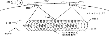
图21(a)和21(b)按照本发明的一个示范实施例图示了连续激励模式;Figures 21(a) and 21(b) illustrate continuous excitation patterns according to an exemplary embodiment of the present invention;
图22是一个框图,图示了本发明的动态信道分配实施例的一个示范实现的组成部分;Figure 22 is a block diagram illustrating the components of an exemplary implementation of the dynamic channel allocation embodiment of the present invention;
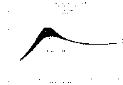
图23是一个圆形对称、一致孔径激励函数的示范辐射方位图的一个图解表示;Figure 23 is a graphical representation of an exemplary radiation pattern for a circularly symmetric, uniform aperture excitation function;
图24是相对信号增益相对波束交叉点的示范图;Figure 24 is an exemplary graph of relative signal gain versus beam intersection;
图25是一个示范图,图示了3网眼频率复用模式中C/I与网眼中移动台位置的关系;Figure 25 is an exemplary diagram illustrating the relationship between C/I and the position of the mobile station in the cell in a 3-cell frequency reuse pattern;
图26是一个图解C/I与波束边缘交叉点关系的示范图;Figure 26 is an exemplary diagram illustrating the relationship between C/I and beam edge intersections;
图27是一个中频复用系统中C/I对网眼中移动台位置关系的不范图;Figure 27 is an exemplary diagram of the positional relationship of the mobile station in the C/I pair cell in an intermediate frequency multiplexing system;
图28是一个中频复用系统中C/I对波束边缘交叉点关系的示范图;Figure 28 is an exemplary diagram of the relationship between C/I and beam edge intersections in an intermediate frequency multiplexing system;
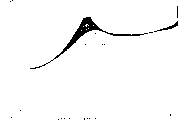
图29图示了一个圆形对称,1/2余弦孔径激励函数的示范辐射方位图;Figure 29 illustrates an exemplary radiation pattern for a circularly symmetric, 1/2 cosine aperture excitation function;
图30是图29中的激励函数方位图的相对信号增益对波束交叉点关系的示范图;Figure 30 is an exemplary plot of relative signal gain versus beam crossing point for the excitation function azimuth diagram of Figure 29;
图31是一个示范图,图示了图29中的激励函数的3网眼复用模式的C/I对网眼中移动台位置的关系;Figure 31 is an exemplary diagram illustrating the C/I versus mobile station position in a cell for the 3-cell multiplexing pattern of the excitation function in Figure 29;
图32是一个示范图,图示了图29中的激励函数的3网眼复用模式中,在25%的网眼半径内,C/I对所有移动台位置处的波束交叉点的关系;Figure 32 is an exemplary graph illustrating C/I versus beam intersections at all mobile station locations within a 25% cell radius for the 3-cell multiplexing pattern of the excitation function in Figure 29;
图33是一个示范图,图示了图29中的激励函数的中频复用中,C/I对网眼中移动台位置之间的关系;Figure 33 is an exemplary diagram illustrating the relationship between the C/I pair and the position of the mobile station in the cell for intermediate frequency multiplexing of the excitation function in Figure 29;
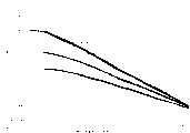
图34是一个示范图,图示了使用图29中的孔径激励函数的一个中频复用系统,在波束边缘交叉点上按dB下降函数的25%网眼半径内所有点上的C/I;Figure 34 is an exemplary diagram illustrating the C/I at all points within 25% of the cell radius of the dB down function at beam edge intersections for an IF multiplexing system using the aperture excitation function of Figure 29;
图35图示了按照本发明的示范实施例的波束和网眼方位图;Figure 35 illustrates a beam and cell azimuth diagram according to an exemplary embodiment of the present invention;
图36图示了另一个使用七个通信信道的示范波束和网眼方位图;Figure 36 illustrates another exemplary beam and cell pattern using seven communication channels;
图37是一个框图,为按照本发明的另一个示范实施例的一个固定波束形成装置;FIG. 37 is a block diagram of a fixed beamforming device according to another exemplary embodiment of the present invention;
图38是按照本发明的一个示范实施例波束形成装置的当前射入和发放点的表;以及FIG. 38 is a table of current injection and emission points of a beamforming device according to an exemplary embodiment of the present invention; and
图39图示了图37的波束形成装置的一个示范TDMA实施例。FIG. 39 illustrates an exemplary TDMA embodiment of the beamforming apparatus of FIG. 37 .
详细描述 A detailed description
首先,理解与普通天线阵列信号发射有关的干扰问题是有益的,例如图3中所示的那种天线。图4表示了天线在地面上产生的辐射强度的交叉面,例如图3中所示的那种天线。即使在最佳的干扰情况下,此时一个移动单元位于波束2(点A)的中心,从波束1和3来的辐射并不为0,只是相当程度地减弱了。移动台2接收到的总信号可以描述为三个分量之和,即:First, it is beneficial to understand the interference issues associated with signal transmission from common antenna arrays, such as the one shown in Figure 3. FIG. 4 shows the cross-section of the radiation intensity produced on the ground by an antenna, such as the one shown in FIG. 3 . Even in the best interference situation, where a mobile unit is centered in beam 2 (point A), the radiation from
C21的大小乘以波束1的信号S1(小)The magnitude of C21 is multiplied by the signal S1 of beam 1 (small)
C22的大小乘以波束2的信号S2(大)The magnitude of C22 is multiplied by the signal S2 of beam 2 (large)
C23的大小乘以波3的信号S3(小)The magnitude of C23 is multiplied by the signal S3 of wave 3 (small)
现在考虑相反(上行链路)方向,并假设可逆传播,卫星在波束2中接收到来自三个移动台的辐射成分,称为C21·M1+C522·M2+C23·M3,此处M1、M2、M3分别是网眼1、2和3中的移动台发射的信号。如果移动台1并不靠近波束2的边缘,那么C21将很小;因为移动台2在波束2之中,C22将很大;并且如果移动台3不靠近波束2的边缘,C23将很小。因此只要移动台被理想地安置且不在网眼的边缘,那么网眼间干扰的等级将是可以容忍的。Now considering the opposite (uplink) direction, and assuming reversible propagation, the satellite receives radiation components from three mobile stations in
另一方面,例如,如果一个移动单元靠近网眼1和网眼2之间的边界,系数C21将很大且M1将干扰信号M2的解码。防止这个问题传统的技术是在紧邻的网眼中不使用相同的频率。例如,可能使用图5所示的3-网眼频率复用模型。图5中带阴影的网眼使用第一个频率f1,所示的模型中的其它网眼使用f2和f3。可以看出,使用相同频率f1的网眼不相邻,并且边与边之间的间隔恰小于一个网眼直径。一个波束边缘的移动台位于使用相同频率的其它网眼的辐射强度曲线很低点的位置。然而,该方法的缺陷是每个网眼内只能使用三分之一的可用频率,频谱利用率以三为因子降低。所以,本发明在其它特性之中提供了一种取消同信道干扰而不损失频谱利用率的方法,并相应避免了在相邻网眼中不能使用频谱复用的弊病。On the other hand, for example, if a mobile unit is close to the border between
如果在所有波束B1、B2、B3……等等中接收的信号的表达式收集在一起,并暂时假设移动台信号与波束有相同的个数,那么产生下列方程组:If the expressions for the signals received in all beams B1, B2, B3, ... etc. are collected together, and tentatively assuming that the mobile signal has the same number of beams, then the following system of equations results:
B1=C11·M1+C12·M2+C13·M3+C14·M4…C1n·MnB1=C11·M1+C12·M2+C13·M3+C14·M4...C1n·Mn
B2=C21·M1+C22·M2+C23·M3+C24·M4…C2n·MnB2=C21·M1+C22·M2+C23·M3+C24·M4...C2n·Mn
B3=C31·M1+C32·M2+C33·M3+C34·M4…C3n·MnB3=C31·M1+C32·M2+C33·M3+C34·M4...C3n·Mn
…………………………
Bn=Cn1·M1+Cn2·M2+Cn3·M3+Cn4·M4…Cnn·MnBn=Cn1·M1+Cn2·M2+Cn3·M3+Cn4·M4...Cnn·Mn
该方程组可简写为B=C·M,此处B和M是列矢量,C是一个n×n的系数方阵。The system of equations can be abbreviated as B=C·M, where B and M are column vectors, and C is an n×n coefficient square matrix.
从卫星每个波束中接收的信号中,希望能确定移动台发射的信号;按照本发明可以通过解上面的方程组而得到所需的信号:M=C-1·BFrom the signal received in each beam of the satellite, it is hoped that the signal transmitted by the mobile station can be determined; according to the present invention, the required signal can be obtained by solving the above equations: M=C-1 B
只要矩阵C是可逆的(即,有一个非零的行列式),这个解就可以得到,其结果实际上消除了移动信号之间所有的干扰,使它们之间达到完全的分离。上述方程的所有元素,即移动信号Mi,波束信号Bk以及矩阵元素Cki均为具有实部和虚部的复数,使之不仅可以表示信号幅度的差别,也可以表示信号之间的相位关系。按照本项发明,从不同天线波束中接收的信号在相同的时间按照奈奎斯特准则以足够捕获所有感兴趣的信号成份的速率进行抽样。一组这样的样值在任何时刻都可形成列矢量B,每个这样的矢量被C的逆相乘,例如,每个抽样周期乘一次得到一组样值M,代表自由移动信号干扰。M的相同元素的一系列值形成样本流,对应于一个移动信号。这个流送入每个移动信号的数字信号处理器中,将样本流转换成,例如,一个模拟的话音波形或64KB的PCM数字语音流,该语音流是系统所连接的电话交换系统所需要的。As long as the matrix C is invertible (ie, has a non-zero determinant), this solution can be obtained, and the result is that virtually all interference between the mobile signals is eliminated, resulting in complete separation between them. All the elements of the above equation, namely the mobile signal Mi, the beam signal Bk and the matrix element C ki are complex numbers with real and imaginary parts, so that they can represent not only the difference in signal amplitude, but also the phase relationship between signals. According to the present invention, the signals received from the different antenna beams are sampled at the same time according to the Nyquist criterion at a rate sufficient to capture all signal components of interest. A set of such samples forms at any time a column vector B, and each such vector is multiplied by the inverse of C, for example, once per sampling period to obtain a set of samples M representing free-moving signal interference. A sequence of values of the same element of M forms a stream of samples, corresponding to a movement signal. This stream is fed into each mobile digital signal processor, which converts the sample stream into, for example, an analog voice waveform or a 64KB PCM digital voice stream as required by the telephone switching system to which the system is connected .
按照本发明的另一特性,矩阵C不必在每个抽样周期求逆,可以减少求逆的频率或只在每个通话的开始处求一次逆。矩阵C和它的逆相对变化较慢因为C系数的改变频率与移动单元在波束中移动位置有关,或者在非静止卫星情况下与卫星移动引起的波束辐射密度分布的改变有关,这些变化都是相对较慢的。在本发明的一个示范的卫星实施例中,典型的网眼大小在几百公里的范围内,卫星轨道在中等纬度需要一到两小时才移出一个典型大小的网眼。因为移动而引起的重新计算新的矩阵逆的需要在一个普通的、例如3分钟的电话通话期间不会产生。但是,在逆的C矩阵中做改变将是有益的,主要原因是通话是连续地接通及断开的。如果n=37,例如,平均通话持续3分钟,那么平均来说,一个移动台与它相应的矩阵C的列每5秒被略去一次并代之以另一个系数列。替换发生时引入新的逆C矩阵的处理将在后面解释,只要说明的是:与解调、解码37个移动信号所进行的整个数字信号处理相比这只是微不足道的一点计算而已。According to another feature of the present invention, the matrix C does not need to be inverted every sampling period, and the frequency of the inversion can be reduced or only once at the beginning of each call. The matrix C and its inverse change relatively slowly because the frequency of change of the C coefficients is related to the movement of the mobile unit in the beam, or in the case of a non-stationary satellite, to the change of the beam radiation density distribution caused by the movement of the satellite. These changes are relative to slower. In an exemplary satellite embodiment of the invention, typical cell sizes are in the range of a few hundred kilometers, and satellite orbits at moderate latitudes require one to two hours to move out of a typical sized cell. The need to recalculate a new matrix inverse due to movement does not arise during a normal,
应用这些原则的一个示范实施例现在将参考图6-11予以描述。An exemplary embodiment applying these principles will now be described with reference to FIGS. 6-11.
图6表示了多个便携台420通过卫星410与中心站400通信。该中心站,例如,通过一个本地交换局与一个公用电话交换网(PSTN)相连,以使便携电话可与世界范围的任一电话用户通话,也可以使卫星电话之间相互通话。卫星在相对较低的微波频率,例如1600MHz接收来自便携机的信号。在这样的频率上,以电池工作的话机的发射机能有效工作并且它们的天线可以是小型的全方向的。卫星从1600MHz接收信号转换成较高的频率,用于转发给中心站。FIG. 6 shows a plurality of
使用一个较高的频率是因为卫星到中心站的链路需要的频带宽度至少是分配给每个波束的1600MHz频段宽度的n倍,n是波束数。例如,如果在1600MHz上,37个波束中的每一个复用了6MHz的一段带宽,那么在卫星到中心站的链路上至少使用37×6或222MHz的频带宽度需要。因为保持相干波束信号传输的方法使用至少两倍于这个起码的最小带宽的频带,并且反向需要相同大小,那么就需1GHz的带宽。由此建议卫星到中心站的前向和返回链路上载频大约是,例如,20GHz比较合适。A higher frequency is used because the satellite-to-hub link requires a frequency bandwidth at least n times the width of the 1600MHz band allocated to each beam, where n is the number of beams. For example, if each of the 37 beams multiplexes a 6MHz bandwidth at 1600MHz, then at least 37×6 or 222MHz of frequency bandwidth needs to be used on the link from the satellite to the central station. Because the method of maintaining coherent beam signal transmission uses a frequency band at least twice this minimum minimum bandwidth, and the reverse requires the same size, then a bandwidth of 1 GHz is required. It is thus suggested that the carrier frequency for the forward and return links from the satellite to the central station is approximately, for example, 20 GHz.
在这样的频率上,即使相对较小的中心站天线也有很窄的波束宽度,使得任何一个系统对这个带宽的独占都是不必要的,整个带宽可以重新分配给其它卫星和地面站,只要从第一个地面站到第一个卫星的视线不与到第二个卫星的视线相交就不会产生干扰。分配唯一的“站”给静止轨道上的卫星可以避免这种情况,或者,对于在较低轨道上移动的卫星这种情况下,交叉的概率很小,当发生交叉时改变中心站位置来解决。At such frequencies, even relatively small central station antennas have narrow beamwidths, making any one system's monopoly of this bandwidth unnecessary, and the entire bandwidth can be redistributed to other satellites and ground stations, simply from There is no interference if the line of sight of the first ground station to the first satellite does not intersect the line of sight to the second satellite. This can be avoided by assigning unique "stations" to satellites in geostationary orbit, or, in the case of moving satellites in lower orbits, where the probability of crossing is small, changing the location of the central station when a crossing occurs .
图7表示了一个将移动台发射的信号转发给中心站的示范性卫星转发器框图。L-波段(即1600MHz)的多波束卫星天线470从分布在不同波束间的多个移动电话接收信号,并在有关的低噪声放大器中放大这些信号。从每个波束来的混合信号包含,例如,从400-500个使用不同频率的移动电话来的信号,这些频率以12.5KHz为间隔,共跨越6MHz的一个总带宽。每个波束的混合信号在相应的混频器440中被下变频以得到基带信号,例如,跨越1-7MHz的范围的信号。这类信号后面将称之为“视频”信号,因为它是摄像机中的信号跨越的典型频率范围。为了将混合的接收信号下变频为视频信号,下变频器可以是,例如,镜像反射类型的下变频器。下变频处理可以选择性地使用合适的中间频率分一步或多步来完成。Figure 7 shows a block diagram of an exemplary satellite repeater for repeating signals transmitted by mobile stations to a central station. An L-band (ie, 1600 MHz)
系统中的下变频器可以使用相同的本振信号以使天线接收的下变频率频率之间保持原有的相位关系。在信道之间偶然引入的固定相位偏差和小的幅度差别都不是问题,因为这可以在中心站通过模拟或数字处理将其校正。The down-converters in the system can use the same local oscillator signal to maintain the original phase relationship between the down-converted frequencies received by the antenna. Fixed phase offsets and small amplitude differences accidentally introduced between channels are not a problem, since they can be corrected by analog or digital processing at the central station.
基带信号用来调制卫星一中心站频带即20GHz中的相应的载波。如果一个1-7MHz的“视频”信号单边带调制到一个20GHz的载波频率上,所得信号将占有20.001到20.007GHz的频带范围。The baseband signal is used to modulate the corresponding carrier in the satellite-hub station frequency band, ie 20 GHz. If a 1-7MHz "video" signal is SSB modulated onto a 20GHz carrier frequency, the resulting signal will occupy a frequency band ranging from 20.001 to 20.007GHz.
但是,使用单边带调制使在波束信号之间保持相位的相干性变得很困难。因此,转而使用双边带调制技术。例如,1-7MHz的视频信号可用来对一个20GHz的载波频率进行频率或相位调制。调制后的载波占据的频率范围大约是19.993-20.007MHz,或者更多,依据使用的频率或相位偏差而定。为了在起码的14MHz带宽周围留一定余量,在20GHz频带内使用25MHz的频率间隔比较合适。因此,在单向的卫星一中心站链路上使用37×25或925MHz的带宽。这个带宽可以用后面描述的正交极化方法的灵活使用将其分为一半。However, using SSB modulation makes it difficult to maintain phase coherence between beam signals. Therefore, double-sideband modulation techniques are used instead. For example, a 1-7MHz video signal can be used to frequency or phase modulate a 20GHz carrier frequency. The frequency range occupied by the modulated carrier is about 19.993-20.007MHz, or more, depending on the frequency or phase deviation used. In order to leave a certain margin around the minimum 14MHz bandwidth, it is more appropriate to use a frequency interval of 25MHz in the 20GHz frequency band. Therefore, a bandwidth of 37 x 25 or 925 MHz is used on the unidirectional satellite-to-hub link. This bandwidth can be divided in half with the flexible use of the orthogonal polarization method described later.
图8表示一个中心站一移动台转发方向的示范卫星转发器。上面描述的移动台到中心站传输的同样方法可以相反地用于多波束信号到卫星的相干传输。中心站(未表示出来)发送多个Ka波段的频率或相位调制的载波到卫星。使用合适的Ka波段天线360接收它们,在共用的低噪声放大器350中放大,然后馈送到FM接收器组340,这里每个载波用相应的接收器解调,产生信号的视频率形式以在相应的波束中传输。这些视频信号,例如占据1-17MHz的频带,在相应的上变频器320中被上变频,使用一个共用的本地振荡器330以保持相对的相位关系,并使用功率放大矩阵310放大信号以便通过多波束天线330发送到移动电话。卫星一移动台链路使用的合适频率,举例来说,为2.5GHz(S-波段)。功率放大矩阵中的放大器可以是线性放大器,以便减少定向到不同电话的信号之间的互调。功率放大器矩阵举例来说,可以是一组n个分立的放大器,每个与相应的波束相关联,或是一组N个(大于或等于n)放大器,其输入端连接有n×N Butler矩阵,输出端连接有N×n的Butler矩阵。Butler矩阵的效果是使用每个放大器放大每个波束信号的一部分,因此平衡了负载,在故障发生时性能稍下降但工作仍可靠,并通过吸收N-n假负载中的互调部分能量来减轻互调。这样的功率放大矩阵的例子可以在美国专利应用系列号—题为“在功率放大器中损失能量控制和管理”中找到,该文发稿于1994年1月11日,这里引为参考。Figure 8 shows an exemplary satellite transponder for a central station-mobile transponder direction. The same method described above for mobile station to hub station transmission can be reversed for coherent transmission of multibeam signals to satellites. A central station (not shown) sends multiple Ka-band frequency or phase modulated carriers to the satellites. They are received using a suitable Ka-
按照本发明的另一个示范实施例,在使用TDMA信号的通信系统中,通过地球轨道卫星做为中继,该卫星具有一个使用这样的矩阵功率放大器的通信转发器,这个功率放大器的输入Butler与放在地面站而不是卫星上的网络相连接。Butler连接操作由地面站的数字信号处理完成,形成所需波束信号的加权求和,产生对应于矩阵功率放大器的每个放大器的驱动信号。这些加权和使用相干馈电链路发送至卫星通信转发器,该转发器接收它们并将其转换到第二频段,以便用这样的方式驱动功率放大器,即,在Butler连接功率放大器输出之后,输出信号就对应于待发送的信号,这些信号以对应于相应的地面终端的不同的天线波束方向发射,这些地面终端举例来说,可能是小型手持便携站。According to another exemplary embodiment of the present invention, in a communication system using TDMA signals, an earth-orbiting satellite is used as a relay, and the satellite has a communication repeater using such a matrix power amplifier whose input Butler and Connected to a network placed on ground stations rather than satellites. The Butler connection operation is completed by the digital signal processing of the ground station, forming the weighted summation of the required beam signals, and generating the driving signal corresponding to each amplifier of the matrix power amplifier. These weighted sums are sent using a coherent feed link to a satcom transponder which receives them and converts them to a second frequency band in order to drive the power amplifier in such a way that after the Butler connects the power amplifier output, the output The signals then correspond to the signals to be transmitted, which are transmitted with different antenna beam directions corresponding to the corresponding ground terminals, which may be, for example, small hand-held portable stations.
最终的卫星流程示于图8(a)。注意一般都存在的输入合成器被省掉了,因为这个功能现在在地面站完成,图中用虚线方框800表示。天线810,包括线性放大器的信号处理820,馈电链路接收器和下变频器830以及输出合成器840可用传统方法实现,这里不再进一步描述。The final satellite process is shown in Fig. 8(a). Note that the normally present input combiner is omitted, as this function is now performed at the ground station, indicated by the dashed
这个实施例在某种情况下很有优点,例如,在天线波束和时隙之间功率的动态重分配可以实现,而不在相应的前向馈电链路信号中产生较大的变化,因为每个馈电链路传输每个波束信号的一部分而不是一个波束信号的全部。另外,在前向馈电链路上发送的信号的预失真可用于进一步补偿相应的转发器信道功率放大器中的失真。此外,在上面引入的“在功率放大器中损失能量控制和管理”的申请中所描述的超维数矩阵功率放大器的这种情况,馈电链路的数目大于将产生的独立的波束信号的数目,因此能够提供足够的冗余措施防止故障。This embodiment is advantageous in certain situations, for example, where dynamic redistribution of power between antenna beams and time slots can be achieved without large variations in the corresponding forward feed link signal, since each Each feeder link transmits a part of each beam signal rather than all of a beam signal. Additionally, predistortion of the signal transmitted on the forward feeder link can be used to further compensate for distortion in the corresponding transponder channel power amplifier. Furthermore, in the case of hyperdimensional matrix power amplifiers described in the above-introduced application "Loss Energy Control and Management in Power Amplifiers", the number of feeder links is greater than the number of independent beam signals that would be generated , thus providing sufficient redundancy against failure.
图9为遵循本发明的一个示范实施例的中心站的框图。该中心站天线600从卫星接收Ka波段的载波,并且在模块610中的共用低噪声放大器和可选的下变频之后,信号在对应于相应的Ka波段载波的多个接收器之间分开以得到波束信号B1…Bn。每个波束信号包括多个语音调制信道频率,它们在信道分离滤波器630中被分离。Figure 9 is a block diagram of a central station in accordance with an exemplary embodiment of the present invention. The central station antenna 600 receives a Ka-band carrier from a satellite, and after a common low-noise amplifier and optional down-conversion in module 610, the signal is split between multiple receivers corresponding to the corresponding Ka-band carrier to obtain Beam signals B1...Bn. Each beam signal includes a plurality of speech modulation channel frequencies, which are separated in channel separation filter 630 .
信道分离滤波器630可以是模拟组件,例如晶体滤波器,并包括一个从可选的信道频率到公共的较低频率(即,12.5-25KHz,或455KHz)的频率变换,以便进行A/D(模/数)变换。已经变换为合适的频率的选定信道信号在A/D(模/数)变换器640中进行A/D变换。在较低的中频,例如455KHz这样的频率上较合适的示范性模数变换器技术是美国专利5,048,059Paul W.Dent的题为“对数一极座标信号处理”中描述的技术,这里引入参考,它通过同时数字化相位和幅度的方法保留信号完整的复数性质。瞬时相位可以使用这样的方法数字化,例如美国专利5,084,669 Paul W.Dent题为“直接相位频率数字化”中描述的技术,这里也引为参考。对应于一个信道频率的所有n个波束信号的相位数字化可使用这里描述的技术实现,即重复某些元件(即,触发器电路和保持寄存器),n次并共享其它的(即,参考频率计数器)以保持相对的相位相干性。另一种方法,如果混合波束信号首先数字化就可使用数字滤波器而不是模拟滤波器,在这种情况下,图9中的A/D变换器640就不需要。Channel separation filter 630 may be an analog component, such as a crystal filter, and includes a frequency conversion from selectable channel frequencies to a common lower frequency (i.e., 12.5-25 KHz, or 455 KHz) for A/D ( Analog/digital) conversion. The selected channel signal that has been converted to an appropriate frequency is A/D converted in an A/D (Analog/Digital) converter 640 . An exemplary analog-to-digital converter technique suitable at lower intermediate frequencies, such as 455 KHz, is that described in U.S. Patent 5,048,059 Paul W. Dent, entitled "Log-Polar Signal Processing," incorporated herein by For reference, it preserves the complex nature of the signal intact by simultaneously digitizing the phase and magnitude. The instantaneous phase can be digitized using methods such as those described in US Patent 5,084,669 Paul W. Dent entitled "Direct Phase Frequency Digitization", also incorporated herein by reference. Phase digitization of all n beam signals corresponding to a channel frequency can be achieved using the techniques described here, i.e. duplicating certain elements (i.e. flip-flop circuits and holding registers) n times and sharing others (i.e. reference frequency counter ) to maintain relative phase coherence. Alternatively, digital filters can be used instead of analog filters if the mixed beam signal is digitized first, in which case the A/D converter 640 in FIG. 9 would not be needed.
A/D变换的数值结果逐样点地馈送到数值矩阵处理器650中。每个信道频率有一个这样的处理器,但为清楚起见,图中只表示了信道频率(m)的处理器。矩阵处理器处理数字化的波束信号,将多至n个独立的移动电话发送的M1……Mn分开,并将对应于每个移动电话发射信号的样本流传输至话音信道处理器660中。话音信道处理器数值化地完成信号的解调、纠错解码以及将数字化的语音从卫星使用的比特率和格式转换成标准的PCM电话系统格式的译码,以便通过一个数字交换机(图中未表示)连结至PSTN。因此图9中所示的示范结构完成了n×m话音信道的解码,此处n是波束的个数,m是每个波束频率的个数。例如,若n=37,m=400,系统就具有14800个话音信道容量的潜力:The numerical results of the A/D conversion are fed into the numerical matrix processor 650 on a sample-by-sample basis. There is one such processor for each channel frequency, but only the processor for channel frequency (m) is shown in the figure for clarity. The matrix processor processes the digitized beam signals, separates M1 . . . Mn of up to n individual mobile-telephone transmissions, and streams samples corresponding to each mobile-telephone transmission to the voice channel processor 660 . The voice channel processor numerically completes signal demodulation, error correction decoding, and converts the digitized voice from the bit rate and format used by the satellite into the standard PCM telephone system format, so as to pass through a digital switch (not shown in the figure) Indicates) link to PSTN. The exemplary structure shown in Fig. 9 thus performs decoding of n x m voice channels, where n is the number of beams and m is the number of frequencies in each beam. For example, if n=37, m=400, the system has the potential of 14800 voice channel capacity:
图9的说明是关于每个频率传输一路话音信道的系统(即,一个频分复用多址(FDMA)系统)。但是,本发明也可用于时分多址(TDMA)系统。在TDMA系统中,通过将一个重复的帧周期分成时隙而将几个移动电话信号在同一信道频率上传输,分配每一帧中的一个时隙给一路移动电话信号。图9的示范框图也可用于从模数变换器640出来的样本流代表TDMA信号时的情况。但是,矩阵处理器650此时将在每个时隙中分开一组不同的移动信号,矩阵系数在对应于时隙的向组之间复用,其中每个相应于一个时隙。这是一个经济的组合,因为对于给定的多个话音信道组合来说,信道滤波器630将在数量上按照每个载波的时隙数做因子而减少,模数变换器相应更少,矩阵处理器的数目相应减少,,但是每个处理器将在较高的输入样本速率上工作,每个话音信道处理器可以顺序地处理连续时隙中的信号,因此经济地使器件进行时间共享而实现相同总数的话音信道容量。The illustration of FIG. 9 is for a system in which one voice channel is transmitted per frequency (ie, a frequency division multiple access (FDMA) system). However, the invention can also be used in Time Division Multiple Access (TDMA) systems. In the TDMA system, several mobile phone signals are transmitted on the same channel frequency by dividing a repeated frame period into time slots, and a time slot in each frame is allocated to one mobile phone signal. The exemplary block diagram of FIG. 9 can also be used when the stream of samples from the analog-to-digital converter 640 represents a TDMA signal. However, matrix processor 650 will now separate a different set of mobile signals in each time slot, and the matrix coefficients are multiplexed between groups corresponding to time slots, each corresponding to a time slot. This is an economical combination because for a given combination of multiple voice channels, the number of channel filters 630 will be reduced by a factor of the number of slots per carrier, correspondingly fewer analog-to-digital converters, and the matrix The number of processors is correspondingly reduced, but each processor will operate at a higher input sample rate, and each voice channel processor can sequentially process signals in consecutive time slots, thus economically allowing devices to be time-shared rather than Achieve the same total voice channel capacity.
所示的每个数值矩阵处理器650接收一路控制信号。控制信号可以由一个分立的计算机(图中未表示)产生,该计算机控制移动电话通话的连结和拆除,需要改变到处理器使用的系数矩阵以便从波束中分离出移动信号。前面提到过如果C矩阵的逆在数值上不是病态的,这种分离就可以实现。如果两个移动台精确地位于地面上的同一点,它们所对应的C矩阵的两个列将是相同的,这将导致行列式为0且逆矩阵不存在。因此,使C矩阵可逆的条件是移动台在地面上要分开足够的距离。如果它们彼此非常接近,C矩阵就变为病态的了。Each numerical matrix processor 650 shown receives a control signal. The control signal can be generated by a separate computer (not shown) which controls the connection and disconnection of the mobile phone call, requiring changes to the coefficient matrix used by the processor to separate the mobile signal from the beam. It was mentioned earlier that this separation can be achieved if the inverse of the C matrix is not numerically ill-conditioned. If two mobiles are located at exactly the same point on the ground, the two columns of their corresponding C matrix will be the same, which will result in a determinant of 0 and no inverse. Therefore, the condition for making the C matrix invertible is that the mobile stations are separated by a sufficient distance on the ground. If they are very close to each other, the C matrix becomes ill-conditioned.
按照本发明的一种情况,当这种状况发生时,两个(或多个)接近的移动台之一将会改变频率到与其确实分开的,使用同一频率的其它移动台使用的信道上。控制计算机具有这样的功能,即,至少在通话建立以及随后可选择的一个间隙里决定哪一个可用信道频率最适合分配给一个新的移动台,或者结束一个正在进行的通话。如果系统中没有空闲的容量,系统就称之为阻塞,用户不能打电话,会使他们感到很恼火。当系统欠载时,至少在某些频率上,移动信号数少于波束数,因此矩阵C就不是方阵了。后面将会看到在欠载的系统中提供的多余的自由度是如何使用的,不仅是用来将移动信号彼此分开以防止相互的干扰,同时也为了增加从最差情况的移动台接收的信号质量。当必须加入一个额外的移动信号时这个方案要改变,而且控制计算机能够预先估计到对信号质量的潜在影响。因此,按照本发明的示范实施例来分配信道的策略是通过在计算中包括进新的信号来估计每个信道上对应于最差情况移动站的信号质量所受到的影响。受到最少的衰减或者对于最差情况的移动台来说,满足最高质量的信道将在逻辑上选为新信号使用的信道。结果是一组指定为相同频率的移动台在空间上将尽可能地分得足够远。According to one aspect of the invention, when this situation occurs, one of the two (or more) approaching mobile stations will change frequency to a channel used by other mobile stations using the same frequency which is actually separated from it. The control computer has the function to decide which of the available channel frequencies is most suitable for assignment to a new mobile station, or to end an ongoing call, at least during call setup and optionally thereafter. If there is no free capacity in the system, the system is said to be blocked, and users cannot make calls, which can be very annoying to them. When the system is underloaded, at least on some frequencies, there are fewer mobile signals than beams, so matrix C is not square. It will be seen later how the extra degrees of freedom provided in underloaded systems are used not only to separate mobile signals from each other to prevent mutual interference, but also to increase the received Signal quality. This scheme is changed when an additional mobile signal must be added, and the control computer can anticipate the potential impact on signal quality. Therefore, the strategy for allocating channels according to an exemplary embodiment of the present invention is to estimate the impact on the signal quality of the worst case mobile station on each channel by including the new signal in the calculation. The channel that suffers the least attenuation or, for the worst case mobile station, meets the highest quality will logically be selected as the channel to use for the new signal. The result is that a group of mobile stations assigned to the same frequency will be as far apart as possible in space.
10表示了每个波束的“视频”信号相干发送的一种示范性的装置。从第一个天线馈电元件(波束)的下变频器(未表示出来)来的视频信号被馈送到一个20GHz的压控振荡器(VCO)1000的压控输入端。视频信号频率调制VCO。中心频率被所需的信道间隙(即,25MHz)调偏的连续VCO用于从天线馈电元件2、3…到n/2来的信号。按照这个示范实施例信号2的VCO中心频率比信号1高出25MHz(即,1GHz/40),且信号n/2的VCO 1001的频率比信号1高出(n/2-1)×1GHz/40=(n-2)/80GHz。从VCO来的信号在加法器1002中求和,这个加法器可以是,例如,一个波导或微带方向耦合网络,信号的总和在公共放大器1003中放大,该放大器可以是,例如,行波管放大器(TWTA)。10 shows an exemplary arrangement for the coherent transmission of the "video" signal for each beam. The video signal from the downconverter (not shown) of the first antenna feed element (beam) is fed to the voltage controlled input of a 20 GHz voltage controlled oscillator (VCO) 1000 . The video signal frequency modulates the VCO. A continuous VCO whose center frequency is offset by the desired channel spacing (ie, 25MHz) is used for signals from
一个并列的装置用于处理排号为n/2+1到n的另一半视频信号。信号n/2+1的VCO 1004被VCO 1000的信道间隔的一半偏置(即,12.5MHz在上面例子中信道间隔是25MHz),这种偏置保持到VCO 1005,使得用于并列装置的这组频率设置均比第一个装置中的信道频率偏离一半。这种方法在双极化传输系统中最小化由不完善的极化隔离而引起的任何干扰。两个TWTA的输出,例如,通过极化器1008连接到双圆极化喇叭天线1009中。极化器1008的作用是激励一个对应于TWTA 1003的信号的右旋圆极化信号到喇叭天线1009,同时激励一个对应于TWTA 1007的信号的左旋圆极化信号。A parallel arrangement is used to process the other half of the video signals numbered n/2+1 to n. The
在中心站,混合信号由双圆极化天线接收,且两上极化信号被分成FM接收器的两个相应的组。FM接收器的中心频率对应于图10中的VCO的中心频率。FM接收器的解调输出重新产生了在卫星L波段天线元件接收的信号,保留了它们之间相位和幅度关系。图11表示了两个极化信号在K波段传输频谱之间的典型关系,可看出在RHC和LHC中心频率之间的半信道偏移是如何缩小相互干扰的。At the central station, the mixed signal is received by dual circularly polarized antennas, and the two upper polarized signals are split into two corresponding groups of FM receivers. The center frequency of the FM receiver corresponds to the center frequency of the VCO in FIG. 10 . The demodulated output of the FM receiver reproduces the signal received at the satellite's L-band antenna elements, preserving their phase and amplitude relationships. Figure 11 shows a typical relationship between the K-band transmission spectrum of two polarized signals, showing how a half-channel offset between the RHC and LHC center frequencies minimizes mutual interference.
在技术上很熟练的人将很容易地感到图10的框图只是根据本发明的一个相干信号传输的典型装置的说明,且存在很多由此而来的功能性等价的流程。例如,首先具有优势的是产生低于20GHz,例如2-3GHz的频率调制信号,并且在求和之后,通过将求和信号与共用的18GHz本振混合以及用一个带通滤波器选出上边带来将混合信号转换到20GHz。Those skilled in the art will easily feel that the block diagram in FIG. 10 is only an illustration of a typical device for coherent signal transmission according to the present invention, and there are many functionally equivalent processes derived therefrom. For example, it is first advantageous to generate a frequency modulated signal below 20 GHz, say 2-3 GHz, and after summing, select the upper sideband by mixing the summed signal with a common 18 GHz local oscillator and using a bandpass filter to convert mixed signals to 20GHz.
上述讨论集中于卫星L波段天线元件接收的信号到中心站的相干传输。相同的功能,称为在中心站产生的信号的传输,相反地用于相应的卫星天线元件—即图8中的转发器—的辐射。中心站可以使用类似图10的装置,但是具有一套与卫星到中心站方向使用的不同的K波段频率,且在地面端有一个较大的天线。卫星可以使用第二个双极化喇叭天线接收,或者另一种办法,使用与图10中同样的喇叭天线和极化器1008、1009,并附带一个发/收双工滤波器给每个极化信号以分开发送和接收的信号。线性放大器350可以为每个极化信号复制一个,用于馈送FM接收器组340相应的一半。两个极化信号的载波之间相同的半信道频率偏移是中心站到卫星方向中的另一个优势。The above discussion has focused on the coherent transmission of signals received by the satellite L-band antenna elements to the central station. The same function, referred to as the transmission of the signal generated at the central station, is instead used for the radiation of the corresponding satellite antenna elements, namely the transponders in FIG. 8 . The central station could use a setup similar to that of Figure 10, but with a different set of K-band frequencies than that used in the satellite-to-central station direction, and with a larger antenna at the ground end. Satellites can be received using a second dual-polarized horn antenna, or alternatively, using the same horn antenna and
图12表示了按照本发明的另一个示范实施例的一个替换装置,用于相干传输中心站到卫星之间的多个信号。在这个图中,对应于一个天线馈送元件的每个卫星转发器信道被表示为一个双下变频过程,包括一个天线滤波器1200、低噪声放大器1201、镜像反射滤波器1202、第一下变频器1203、IF滤波器1204、1206,IF放大器1205以及正交下变频器1207、1208。第一个下变频器1203可以在所有信道中使用相同的本地振荡器信号以保持相对的相干性。正交下变频器1207和1208可以对所有的信道使用相同的第二本地振荡器的余弦和正弦参考信号,同样保持相对的相干性。正交下变频器的输出,例如在0-3MHz的范围,在交叉网络1209中被分成线1215和1216上的0-50KHz的成分以及线1217和1218上的50KHz-3MHz的成分。50KHz到3MHz的成分对应于上行的业务信道,使用如FDMA、FDMA加窄带CDMA混和式或窄带FDMA/TDMA,并且用于调制分离的I和Q、K波段发射机,将这些信号相干地转发到中心站。这些成分调制I、Q压控振荡器1210和1211。这些振荡器的输出在K波段求和网络中求和,并将求和信号馈送到共用的TWTA,以便放大到所需的下行链路发送功率电平。合成半个VCOS,即I VCO到第一个TWTA形成使用RHC极化发送的信号,另一半使用LHC发送,这也是有好处的。中心站中可使用类似的装置以便将每个波束的混和信号相干地输送到卫星。Figure 12 shows an alternative arrangement for coherently transmitting multiple signals from a central station to a satellite, according to another exemplary embodiment of the present invention. In this figure, each satellite transponder channel corresponding to an antenna feed element is represented as a double downconversion process, including an
相应的K波段接收器将为每个I信号和每个Q信号包括一个FM接收器。这些FM接收器应该有较好的自动频率控制(AFC)功能,以便去掉DC和I、Q信号的低频成分,等于是在信道中间的频率向应曲线上有一个凹口。这对于宽带的TDMA信号影响不大,对于FDMA简单地意味着不使用波段中央的信道做传输。A corresponding K-band receiver would include an FM receiver for each I signal and each Q signal. These FM receivers should have a good automatic frequency control (AFC) function to remove the low frequency components of the DC and I and Q signals, which is equivalent to having a notch in the frequency response curve in the middle of the channel. This has little effect on wideband TDMA signals, and for FDMA it simply means not using the channel in the center of the band for transmission.
在卫星上,K波段接收器的输出重新形成I和Q信号,用于使用正交调制器调制余弦和正弦L波段载波,以产生相干的波束信号。这些信号提供给每个波束的L波段功率放大器或前面提到的矩阵类型的PA。On the satellite, the output of the K-band receiver re-forms the I and Q signals, which are used to modulate the cosine and sine L-band carriers using quadrature modulators to produce coherent beam signals. These signals are fed to each beam's L-band power amplifiers or the aforementioned matrix-type PAs.
使用的频率装置可类似于图11中描述的那些,带有RHC极化用于如I成分以及LHC极化用于Q成分,载波间隔减小了以使之与3MHz的调制信号而不是7MHz的信号相当。在RHC和LHC极化载波之间半信道的偏移也是这个I、Q方法的优点。The frequency set-up used could be similar to those described in Figure 11, with RHC polarization for e.g. the I component and LHC polarization for the Q component, with the carrier spacing reduced to match the modulation signal at 3 MHz instead of 7 MHz. Signal quite. The half-channel offset between the RHC and LHC polarized carriers is also an advantage of this I,Q method.
I和Q信号分别代表复数的接收信号矢量在实和虚轴上的投影,在I和Q信号之间保留正确的幅度关系将保留包括相对相位在内的矢量关系。2n个I和Q视频信号可用于频率调制2n个K波段载波,使用只是前述的图10中一半的信道间隔,例如10MHz。使用这种方法显示出在K频段上更高的频谱利用率,但是实际上很难处理由于DC偏置和频率错误而使I、Q信号成分下降到确实为0的频率。The I and Q signals represent the projections of the complex received signal vector onto the real and imaginary axes, respectively. Preserving the correct magnitude relationship between the I and Q signals will preserve the vector relationship including relative phase. 2n I and Q video signals can be used to frequency modulate 2n K-band carriers using only half the channel spacing as in Figure 10 above, eg 10 MHz. Using this approach shows higher spectrum utilization at the K band, but it is practically difficult to deal with frequencies where the I,Q signal components drop to indeed 0 due to DC offset and frequency errors.
因此需要引入AC耦合,要从传输的0-3MHz视频信号中排除一部分,例如0-50KHz。这会在本典型方法转发的6MHz宽的L波段带宽的中间设置一个凹口。根据信号的性质,这个凹口可能无关紧要。例如,在共同未决申请中,共同指定的美国专利申请系列号——题为“TDMA/FDMA/CDMA混合天线接入方法”,发表于1994年1月11日,这里引入参考,它公开了一个适于卫星蜂窝应用的混合接入方法,其中信号在下行链路上(卫星到移动台)按宽带TDMA传输,其中每个移动信号占用相应的帧结构中一个指定的时隙,在上行链路(移动台到卫星)中按频分多址(FDMA)或FDMA和码分多址(CDMA)的混合传输。例如,每秒6.5536兆比特的TDMA信号包括512个时隙,可以从中心站通过每个卫星天线馈送单元6MHz带宽传送到每个网眼中相应数目的移动电话。信道中央带宽的一部分的丢失不会显著地影响这样的信号的性质,而且这种影响如果发生,可以在接收的无线信号中使用DC偏置补偿技术进行补偿,该技术包括在公共指定的美国专利5,241,702,Paul W.Dent的题为“天线接收机中的D.C偏置补偿”,这里引为参考。Therefore, AC coupling needs to be introduced, and a part, such as 0-50KHz, should be excluded from the transmitted 0-3MHz video signal. This places a notch in the middle of the 6 MHz wide L-band bandwidth forwarded by the present exemplary method. Depending on the nature of the signal, this notch may not matter. For example, co-assigned U.S. Patent Application Serial No., entitled "TDMA/FDMA/CDMA Hybrid Antenna Access Method," published Jan. 11, 1994, hereby incorporated by reference, discloses A hybrid access method suitable for satellite-cellular applications, where signals are transmitted on the downlink (satellite to mobile station) as wideband TDMA, where each mobile signal occupies a designated time slot in the corresponding frame structure, and on the uplink Transmission by Frequency Division Multiple Access (FDMA) or a mix of FDMA and Code Division Multiple Access (CDMA) over the road (mobile station to satellite). For example, a TDMA signal of 6.5536 megabits per second includes 512 time slots and can be transmitted from the central station to a corresponding number of mobile phones in each cell through each satellite antenna feed unit 6MHz bandwidth. The loss of a portion of the channel's central bandwidth does not significantly affect the properties of such signals, and such effects, if they occur, can be compensated for in the received wireless signal using DC offset compensation techniques covered in commonly assigned U.S. Patent 5,241,702, by Paul W. Dent, entitled "D.C Offset Compensation in Antenna Receivers", incorporated herein by reference.
当在下行链路中使用这样的512时隙的TDMA格式时,一个或多个时隙可以指定用做公共信令信道,也称为呼叫信道、前向控制信道或寻呼信道。系统使用呼叫信道将始发于网络的呼叫广播到移动电话(即,从一个PSTN用户或从另一个移动电话)。当一个移动台在这样一个广播信息中检测到它自己的电话号码或ID时,它使用一个相应的上行链路信道—一般称为“随机访问信道”—来做应答。之所以称为随机访问信道是因为移动电话也使用它放置移动台始发的呼叫,即从网络请求服务。当存在大量的漫游移动电话时,这些请求事件对系统来说是随机涨落的。When such a 512-slot TDMA format is used in the downlink, one or more time slots may be designated as common signaling channels, also known as calling channels, forward control channels or paging channels. The system broadcasts network-originated calls to mobile phones (ie, from a PSTN user or from another mobile phone) using call channels. When a mobile station detects its own telephone number or ID in such a broadcast message, it uses a corresponding uplink channel—commonly called a "random access channel"—to reply. It is called a random access channel because mobile phones also use it to place mobile-originated calls, ie requests for service from the network. These request events fluctuate randomly to the system when there are a large number of roaming mobile phones.
按照前面提到的“TDMA/FDMA/CDMA混合访问方法”专利申请,每一个下行链路时隙都与相应的上行链路载波频率相关联。因此为了与本发明的I、Q型式一起使用上述的发明,与下行链路呼叫信道时隙相关联的上行链路载波频率可以选为对应于6MHz带宽中央的±50KHz,并用做随机访问信道。According to the aforementioned "TDMA/FDMA/CDMA Hybrid Access Method" patent application, each downlink time slot is associated with a corresponding uplink carrier frequency. Thus to use the above described invention with the I,Q versions of the invention, the uplink carrier frequency associated with the downlink paging channel slots can be chosen to correspond to ±50KHz in the middle of the 6MHz bandwidth and used as the random access channel.
因此,从交叉网络1209来的0-50KHz的信号代表随机访问信号,并且由于它们相对较低的带宽,在线数字化的选择和通过数字方式传输到中心站都是存在的。模数变换器1212完成这个任务,它的每个信道的输出在复用器1213中进行复用,以形成量级为60MB/S的混合比特流,该比特流调制数字发射机1214以便发送到中心站。Thus, the 0-50 KHz signals from the
按照另一个典型实施例,天线元信号可以在地面站和不带频带扩展的卫星之间相干地传输。图13和14用图表示了一个典型的相干传输方法以及装置,该装置基于每个天线信号模拟到数字的转换,跟随一个数字复用器,通过正交幅度调制将复用流调制到K波段馈电链路载波上。图15图解表示了一个从图13得来的替代装置,它等于无限的模到数以及数到模的精度,因此允许图13典型实施例的模到数以及数到模的设备都由模拟复用器来替换。According to another exemplary embodiment, antenna element signals may be transmitted coherently between a ground station and a satellite without band extension. Figures 13 and 14 diagrammatically represent a typical coherent transmission method and apparatus based on the analog-to-digital conversion of each antenna signal followed by a digital multiplexer to modulate the multiplexed stream into the K-band by quadrature amplitude modulation on the feeder link carrier. Fig. 15 schematically shows an alternative arrangement derived from Fig. 13, which equals infinite analog-to-digital and digital-to-analog accuracy, thus allowing both analog-to-digital and digital-to-analog devices of the exemplary embodiment of Fig. 13 to be analog complexed. Replace it with a device.
参考图13,这个相干传输系统的操作如下。从多个卫星上带的天线元之一接收的2GHz的信号被进行低噪声放大并使用混频器1301和1302对应于余弦和正弦的本振信号进行下交频。如果2GHz的带宽被下变频为5MHz,那么所得的I、Q信号每个带宽为2.5MHz。因此所需的5MHz的带宽通过使用2.5MHz的截止低通滤波器1304、1305作用于I、Q信号来实现。这些混频器、滤波器以及模数变换器1306、1307对于如此处理的每个分立的天线元信号是重复的。混频器可以接收同一个本振信号cos(WT)和sin(WT)以便在信道之间不引入任何相对的相位差。Referring to Fig. 13, the operation of this coherent transmission system is as follows. The 2 GHz signal received from one of the antenna elements onboard multiple satellites is low-noise amplified and down-crossed using
基带的I、Q信号滤波之后使用模数转换器1306和1307转换。这些用于对I、Q信号在至少为奈奎斯特速率上进行抽样和转换,即两倍于带宽的速率,在本例中为5MS/S。至少以奈奎斯特速率抽样,允许信号能够完全从抽样值进行正确的恢复。举例来说,图中的模数转换器只是两比特的方案,即每个I或Q信号被归为最接近四个值之一:-3、-1、+1或+3个任意单位,用数字码11、10、01或00来表示它们。The baseband I and Q signals are filtered and converted using analog-to-
在某些应用中,两比特量化确实是足够了。这样的应用有如下特点:在5MHz带宽内2GHz处的总的信噪比非常低或甚至为负值。如果人为地加宽信号带宽信噪比可能升高,例如使用编码或扩频技术。如果信噪比很低或为负值,几个比特的方案足够使数字量化噪声低于无线电波噪声,以防衰减。比较精通技术的人将喜欢在应用中使用较高的信噪比、更多的比特以提供更高的精度。In some applications, two-bit quantization is indeed sufficient. Such an application has the following characteristics: the total signal-to-noise ratio at 2 GHz within a 5 MHz bandwidth is very low or even negative. The signal-to-noise ratio may increase if the signal bandwidth is artificially widened, for example by using coding or spread spectrum techniques. If the signal-to-noise ratio is low or negative, a scheme of a few bits is sufficient to keep the digital quantization noise below the radio wave noise, preventing attenuation. The more technically savvy will like to use a higher SNR, more bits, to provide more precision in their application.
在两比特的例子中,代表瞬时I抽样和Q抽样的比特对从所有的天线元中收集,并使用数字复用器1308和1309进行复用。数字复用器1308和1309的输出分别是天线号1的两经特I和两比特Q信号,紧接着是天线号2的相同信号,然后是3、4,等等,直到天线1又被抽样。连续的两比特I、Q值通过调制发送到K波段馈电链路载波频率上。In the two-bit example, bit pairs representing instantaneous I samples and Q samples are collected from all antenna elements and multiplexed using
由于每秒的比特数为4N×5MS/S=20N Mbits/s,需要一种带宽足够的数字调制方案,以避免信号占据超过原来N个信号的5N MHz的带宽。一个合适的调制方案,例如,可以是16QAM。在16QAM中,通过将两比特映射到四个K波段载波的实矢量值(即,余弦载波分量的幅度)之一以及两比特映射到四个虚矢量值(即,正弦分量的幅度)之一,以实现每个传输符号传输器比特数据。产生的4×4的可能点的格点图见图14。使用16QAM,通过数模转换器1310和1311将I比特对映射到K波段I轴,Q比特对映射到K波段Q轴。最后,所需的K波段矢量分量通过将两比特的数模转换器1310和1311的输出提供给K波段正交调制器1312来形成,该调制器由K波段余弦和正弦载波波形(未表示出来)驱动,以形成通过K波段馈电链路天线(也未表示)传输的调制输出信号。Since the number of bits per second is 4N×5MS/S=20N Mbits/s, a digital modulation scheme with sufficient bandwidth is required to prevent the signal from occupying a bandwidth of 5N MHz exceeding the original N signals. A suitable modulation scheme may be, for example, 16QAM. In 16QAM, by mapping two bits to one of the four K-band carrier real vector values (i.e., the magnitude of the cosine carrier component) and two bits to one of the four imaginary vector values (i.e., the magnitude of the sine component) , to implement the transmitter bit data per transmitted symbol. See Figure 14 for the generated 4×4 grid point diagram of possible points. Using 16QAM, I-bit pairs are mapped to the K-band I-axis and Q-bit pairs are mapped to the K-band Q-axis by digital-to-
复用器可以有比天线信道来的信号更多的输入。例如,一个典型的天线排列可以是61个天线元的六角形阵列。那么采用64个输入的复用器比较合适,因为在复用器的结构中输入数是按2的方幂自然增长的。剩余的3个输入可以连接到分别等于(0,0)、(1,0)和(0,1)的参考I、Q信号上。地面站接收器可以使用这些参考信号同步它的解复用,以及从(0,0)情况来确定正交调制载波的泄漏(偏移),从(1,0)和(0,1)情况来提供相位参考以便从Q轴比特分辨出I轴比特。The multiplexer can have more inputs than signals from the antenna channels. For example, a typical antenna arrangement may be a hexagonal array of 61 antenna elements. Then it is more appropriate to adopt a multiplexer with 64 inputs, because in the structure of the multiplexer, the number of inputs increases naturally by the power of 2. The remaining 3 inputs can be connected to reference I, Q signals equal to (0,0), (1,0) and (0,1) respectively. The ground station receiver can use these reference signals to synchronize its demultiplexing, and to determine the leakage (offset) of the quadrature modulated carrier from the (0,0) case, from the (1,0) and (0,1) cases to provide a phase reference to distinguish I-axis bits from Q-axis bits.
在两比特量化不够的情况下,模数转化器1306和1308可采用较高的精度,例如,四比特量化。那么每4比特I和4比特Q抽样代表256种可能之一,采用256Q AM就可以用上述的16Q AM相同的方式传输。但是可以做一个简化,注意到在模块1306、1308中执行的模数转换的求反操作与数模转换器1310和1311中执行的映射到一个符号是简单地互相抵消的,可以从这个替代的示范实施例中删掉。那么从低通滤波器来的模拟I、Q信号的完全的不经过量化的精度在通过复用器之后得以保持,数字复用器由模拟复用器来替代,如图15所示。In the case that two-bit quantization is not enough, the analog-to-
在图15中,基带信号由下变频器1501、1502以及前面根据图13描述的低通滤波器1503、1504来产生。I、Q信号不再数字化,而是直接与其它天线信道(未表示出来)来的相应信号一起进入模拟复用器1505、1506的输入端。复用后的I抽样值继而调制K波段余弦载波,且复用的Q抽样值调制K波段正弦载波,通过使用正交调制器1507来完成。模拟复用器多余的输入端,如前面指出的,可以用于复用,传输诸如(0,0)、(1,0)以及(0,1)这样的参考值,这些参考值有助于地面站接收器获得复用同步,并纠正正交调制器的某些错误,例如载波不平衡(载波泄漏、偏差)以及不完善的正交(即,余弦和正弦载波不是精确地分开90度)。In FIG. 15 , the baseband signal is generated by
图15中表示的配置有一个优点,即从2GHz到K波段时,实际上没有信号的带宽扩展。在2GHz接收的N个5MHz宽的天线信号实际上使用了相同的5N MHz带宽在K波段进行再传输。因此,没有再引入量化噪声。The configuration represented in Figure 15 has the advantage that there is practically no bandwidth extension of the signal when going from 2 GHz to the K-band. The N 5MHz-wide antenna signals received at 2GHz actually use the same 5N MHz bandwidth for retransmission in the K-band. Therefore, no quantization noise is reintroduced.
适用于图15中的示范实施例的一个模拟复用器可以用二进制树来构成,其中5MS/S的信号对首先在相对低速的2输入端复用器中复用形成10MS/S的信号。然后,这些信号对再在较高速的2输入端复用器中复用以形成20MS/S的信号,如此类推。复用器可以使用电流控制的双极CMOS或Bi CMOS集成电路构造,信号输入到两个三极管输入极上(即,射极),控制信号轮流使它们导通或不导通(加到基极上),信号电流或者通过其中的一个器件,或者被推到另一个器件中通过。镓砷化物技术,例如HBT,适合于构造高速的复用器。An analog multiplexer suitable for the exemplary embodiment in Figure 15 can be constructed using a binary tree, where 5 MS/S signal pairs are first multiplexed in a relatively low speed 2-input multiplexer to form a 10 MS/S signal. These signal pairs are then multiplexed in a higher speed 2-input multiplexer to form a 20MS/S signal, and so on. The multiplexer can be constructed using a current-controlled bipolar CMOS or Bi CMOS integrated circuit. The signal is input to the input electrodes of the two transistors (ie, the emitter), and the control signal turns them on or off (applied to the base On), the signal current either passes through one of the devices, or is pushed to pass through the other device. Gallium arsenide technology, such as HBT, is suitable for constructing high-speed multiplexers.
地面站处理系统在K波段上接收时间复用的天线信号,将这些信号下变频到每个2.5N MHz带宽的I、Q基带信号,然后将它们解复用,成为N个各5MS/S,间隔2.5MHz带宽的信号(奈奎斯特速率或更高)。这些信号可以在地面上数字化为任意所需的精度,以便进一步处理,例如,由于K波段发送器、接收器或传播通道上预计的或偶然的带宽限制而使相邻样点间产生模糊,造成样点间的干扰,使用均衡器可以消除这种干扰。这种均衡操作通过从电流值中减去前后复(I、Q)抽样值的一个定义大小来实现,该定义大小由用来去掉抽样间干扰的复系数给定。这种处理也可相反地用于到卫星的传输,使用K波段复信号矢量抽样为在相应的诸如S波段的天线上传输。The ground station processing system receives time-multiplexed antenna signals on the K-band, down-converts these signals to I and Q baseband signals of each 2.5N MHz bandwidth, and then demultiplexes them into N 5MS/S each. Signals spaced at 2.5MHz bandwidth (Nyquist rate or higher). These signals can be digitized on the ground to any desired accuracy for further processing, e.g., due to expected or accidental bandwidth limitations on K-band transmitters, receivers, or propagation channels, resulting in ambiguity between adjacent samples. The interference between samples can be eliminated by using an equalizer. This equalization operation is accomplished by subtracting from the current value a defined magnitude of the preceding and following complex (I, Q) sample values, given by the complex coefficient used to remove inter-sample interference. This process can also be reversed for transmission to satellites, using K-band complex signal vector sampling for transmission on corresponding antennas such as S-band.
N个分立的复(I、Q)抽样流首先在地面站得到很好的预均衡,以便在卫星上接收时不带抽样间干扰。然后时间复用调制的K波段信号在卫星中相对K波段本振进行下变频,给出复用的I、Q流。如果需要的话,可使用两级或多级下变频,以便在合适的中频上进行放大。这也适用于图13中的2GHz下变频器,但要注意到在所有相应的下变频阶段上对每个知线元要使用相同的本振信号,以便不引入相对的相位偏移。The N discrete streams of complex (I, Q) samples are first well pre-equalized at the ground station so that they can be received on the satellite without inter-sample interference. Then the time-multiplexed modulated K-band signal is down-converted relative to the K-band local oscillator in the satellite to give multiplexed I and Q streams. If desired, two or more stages of down conversion can be used to amplify at the appropriate intermediate frequency. This also applies to the 2GHz downconverter in Figure 13, but it is noted that the same LO signal is used for each line element at all corresponding downconversion stages so as not to introduce a relative phase shift.
由卫星接收的复用I、Q流可以使用用于复用器1505和1506的同一个复用时钟(未表示)来解复用。地面站的任务就是在发送信号时要考虑传播时间,以使信号按照正确的定时关系到达,保证到达卫星时能够进行正确的解复用。用这种方法,卫星上的功能保持简单可靠,复杂性限制在地面站中,以便出了故障时能够对设备进行修复。Multiplexed I, Q streams received by satellites can be demultiplexed using the same multiplexing clock (not shown) used for
为了图示清楚起见,上面的描述进行了简化,只考虑了所有天线元信号都时分复用到一个单一的TDM复抽样流中。技术熟练的人很容易理解应当使用混合的TDM/FDM方案,在该方案中形成几组时分复用信号,并用它们来调制分立的FDM载波。举例说,如果一个单个的复用流产生不太实际的较高的抽样率,就要用这种改进的方案。For clarity of illustration, the above description has been simplified to consider that all antenna element signals are time multiplexed into a single stream of TDM complex samples. Those skilled in the art will readily understand that a hybrid TDM/FDM scheme should be used in which sets of time-division multiplexed signals are formed and used to modulate separate FDM carriers. This modification is used, for example, if a single multiplexed stream yields an impractically higher sampling rate.
也是为了图示清楚起见,上面的描述集中于复信号的笛卡尔(I、Q)表示。在调制K波段馈送链路之前使用模拟复用器复用信号时,或者在复用之前使用前面参考的美国专利号5,048,059对信号进行数字化时,形成复信号的极坐标或对数极坐标表示,同样也是可行的。Also for clarity of illustration, the above description has focused on the Cartesian (I,Q) representation of complex signals. A polar or logpolar representation of the complex signal is formed when the signal is multiplexed using an analog multiplexer prior to modulation of the K-band feeder link, or when the signal is digitized prior to multiplexing using previously referenced U.S. Patent No. 5,048,059, The same is also possible.
图16表示了本发明的这个示范实施例的主站中的发送信号处理。每个将发送到移动电话的话音信道可以作为标准的64KB/S的PCM信号接收,或者作为可转的PCM的模拟信号接收。PCM信号可使用典型的话音压缩算法,例如,CELP(码本激励线性预测),RELP、VSELP或子带编码,进行代码转换,以得到较低的比特率,例如4.8KB/S。变换后的话音信号进行纠错编码,并加入附加的比特,例如循环冗余校验比特(CRC),慢关联控制信道信令信息(SACCH),每时隙的同步字以及时隙间的保护符号。每个信道处理在话音处理信道卡1600中进行。从,例如,500个这样的信道卡中输出的比特流在复用器1601中与控制处理器(未表示)来的控制信道数据流一起复用,形成TDMA比特流,例如,以每秒6.5536兆比特的速率。该比特流送到数字调制器1602,将信息流数值转化成代表调制波形的I、Q分量的复数流,该转化以诸如每比特8个样点的抽样速率进行。Fig. 16 shows transmission signal processing in the master station of this exemplary embodiment of the present invention. Each voice channel to be sent to a mobile phone can be received as a standard 64KB/s PCM signal, or as a convertible PCM analog signal. PCM signals can be transcoded using typical speech compression algorithms such as CELP (Codebook Excited Linear Prediction), RELP, VSELP or sub-band coding to obtain a lower bit rate, such as 4.8KB/S. The converted voice signal is error-corrected and encoded, and additional bits are added, such as cyclic redundancy check bits (CRC), slow associated control channel signaling information (SACCH), synchronization word per slot, and protection between slots symbol. Each channel processing takes place in the voice processing channel card 1600. Output bitstreams from, for example, 500 such channel cards are multiplexed in multiplexer 1601 with the control channel data stream from the control processor (not shown) to form a TDMA bitstream, for example, at 6.5536 megabit rate. The bit stream is sent to a digital modulator 1602 which converts the information stream values into a complex stream representing the I and Q components of the modulated waveform at a sampling rate such as 8 samples per bit.
如上面所述产生的TDMA信号是为了发送到第一群,例如,一个给定网眼或区域内的500个移动电话。用类似电话1600、1601、1602形成的其它的这样的TDMA信号是为了传输到36个其它网眼中另外的带500个移动电话的群中。总网眼数(在本示范实施例中即为37个)乘以每个网眼的业务信道数(即,500),就得到如18500个话音信道这样的总体系统容量。每个网眼的时隙1中的信号以相同的频率同时发送到相应的网眼中。为了防止在同时间使用相同频率的相邻网眼之间的泄漏干扰,本发明的这个典型实施例包括矩阵处理器1603,通过对每个时隙使用37×37的复系数矩阵加权求和处理调制器1602来的信号。每个时隙的37×37个系数存贮在系数存储器1605中,该存储器可以分散在数值信号处理器的部件中,但是图16中为了更好地阐明原理,将其综合在一起标志为一个单独的模块1605。在第一个时隙期间,第一套参数C从存储器中选出,与调制器1602出来的调制信号进行矩阵乘,以得到信号,用于数模转换器1604。每个数模转换器是双通道单元,能够与复数进行运算。例如,矩阵处理器的输出信号每个都由12比特的实部(I)和12比特的虚部(Q)组成,经数模转换产生模拟的I、Q信号。I、Q信号馈送到FM K波段FM发射机中,以便从中心站发送到卫星。The TDMA signal generated as described above is intended to be transmitted to a first group, eg, 500 mobile telephones within a given cell or area. Other such TDMA signals formed with similar phones 1600, 1601, 1602 are intended for transmission to another group with 500 mobile phones in 36 other cells. The total number of cells (
当通过卫星在S波段上转发到地面时,矩阵处理的结果是每个移动电话只接收自己的信号,在矩阵处理器中,通过加上存储器1605来的系数确定的相反符号的补偿量抵消了其它网眼来的网眼间干扰。只要在相应网眼中使用时隙1的37个移动台在位置上是分开的,即,没有两个移动台处于网眼边缘的相同位置上,这种处理就是可行的。这个条件通过本发明的典型时隙分配算法特性来保证,它也提供了一个一般的信道分配算法,并基于给最差情况移动台提供最大信号质量的原则。When retransmitting to the ground on the S-band by satellite, the result of the matrix processing is that each mobile phone only receives its own signal. In the matrix processor, the compensation amount of the opposite sign determined by adding the coefficients from the memory 1605 cancels the Intermesh interference from other meshes. This is possible as long as the 37 mobile
如果使用20ms的TDMA帧周期,那么典型地一个时隙的持续时间约为40μs。一个时隙在6.55536MB/S时对应为256个比特周期,调制器1602为每个时隙产生2048个复数值。在矩阵处理器使用第一个时隙的系数集处理2048组37个复数值之后,系数要为第二个以及随后的时隙而改变,以便正确地抵消使用时隙2、3等等的37个移动台的相应组之间的干扰。If a TDMA frame period of 20 ms is used, then typically the duration of a time slot is about 40 μs. A time slot corresponds to 256 bit periods at 6.55536 MB/S, and the modulator 1602 generates 2048 complex values for each time slot. After the matrix processor processes 2048 sets of 37 complex values using the coefficient set for the first slot, the coefficients are changed for the second and subsequent slots to correctly offset the 37 using
如果在不同网眼内使用相同时隙接收的两个移动台在通话过程中过分接近,控制处理器(未表示出来)将会注意到为抵消干扰而产生一套合适的系数是很困难的。按照典型网眼的大小来限制陆地移动电话移动的速度是不太可能的,但是如果发生了上述情况,控制处理器要决定是否需要的其中的一个移动台改变时隙。目的是使用一个附近的移动台不使用的时隙来连接该移动台。如果必要的话,占有一个理想的(即低干扰)时隙的移动台甚至要转移到一个刚刚满足要求(即,免强可容忍的干扰)的时隙,以便释放它原来的时隙,解决当前的位置靠近的问题。事实上可能不必考虑这样的情况,因为,例如从500个时隙中选择的话,很可能会找到较好时隙而不是目前会影响信号质量的时隙。例如允许每10秒中每个网眼有一次时隙改变,可以预计会实现满意的快速的时隙分配的优化以及对移动台移动的令人满意的适应。If two mobile stations receiving on the same time slot in different cells come too close during a call, the control processor (not shown) will notice that it will be difficult to generate an appropriate set of coefficients to cancel the interference. It is unlikely that the speed at which land mobiles can move is limited by the size of a typical cell, but if this occurs, the control processor will decide whether one of the mobiles needs to change time slots. The purpose is to connect to a mobile station using a time slot not used by nearby mobile stations. If necessary, a mobile station occupying an ideal (i.e. low interference) time slot may even move to a time slot that just satisfies the requirement (i.e., free from strong tolerable interference) in order to release its original time slot and resolve the current situation. The problem of the proximity of the location. In fact such a case may not have to be taken into account since, for example, choosing from 500 time slots, it is quite possible to find a better time slot than the one which currently affects the signal quality. Allowing, for example, a slot change per cell every 10 seconds would be expected to achieve satisfactorily fast optimization of slot allocation and satisfactory adaptation to mobile station movement.
实际上,要提供更快的改变速率,以便按照新通话加入,旧通话消除的速率进行处理。在每个时隙37个移动台这样的容量以及平均通话持续3分钟情况下,在一些网眼中大约每5秒中某个时隙被清除一次,新的通话继而分配到该时隙。总之,在本例中,给定500个时隙,37个网眼,每秒中所有网眼中要有100个时隙被消除并重新分配。In practice, a faster change rate is provided so that new calls are added and old calls are removed at the same rate. With a capacity of 37 mobile stations per time slot and an average call duration of 3 minutes, in some cells a time slot is cleared approximately every 5 seconds and a new call is then allocated to that time slot. In summary, in this example, given 500 time slots and 37 cells, 100 time slots from all cells are eliminated and reallocated every second.
这样的一个通信系统不应设计为匀荷达到100%的系统容量,否则下一个通话尝试就会阻塞。每个网眼500个时隙可用时隙,平均负荷为474个时隙就可达到1%的阻塞概率。因此,平均来说,本示范实施例中的37个复用器1302的每一个上的500个时隙要有26个不使用。应该注意到,哪一个复用器用来发送一个特定的时隙到移动台并不是重要的。选定了哪一个时隙,就要选择系数矩阵相关的列,它决定了使用相同时隙的移动台是非干扰的。因此如果在两个或更多的复用器1601上有相同的时隙,例如号码371是空闲的,使用哪一个连接一个新的通话是无关紧要的。Such a communication system should not be designed to load evenly to 100% of the system capacity, otherwise the next call attempt will be blocked. There are 500 time slots available in each cell, and an average load of 474 time slots can achieve a 1% blocking probability. Thus, on average, 26 of the 500 time slots on each of the 37
因此在控制处理器中执行的分配算法首先要确定大多数复用器上哪些时隙是空的。这就是当前最小数量的移动通话所占据的时隙。使用随机存取接收器中有关收自新移动台的信号之间关系的信息(即,由新移动台的随机访问信号与所有天线元信号的相关性决定的C矩阵系数),控制处理器判断需要改变到的系数存储器1605中与某个空时隙—如果新的信号将使用这个空时隙—相关联的系数集以保持无干扰。Therefore the allocation algorithm implemented in the control processor first determines which time slots are free on the majority of the multiplexers. This is the time slot currently occupied by the minimum number of mobile calls. Using the information in the random access receiver about the relationship between the signals received from the new mobile (i.e., the C-matrix coefficients determined by the correlation of the random access signal of the new mobile with all antenna element signals), the control processor determines A change to the set of coefficients in coefficient memory 1605 associated with a certain empty time slot - if the new signal is to use this empty time slot - needs to be changed to remain interference free.
在系数存储器1605中如何为一个示范实施例选择参数的一般原则现在将做一略述。The general principles of how parameters are selected in coefficient memory 1605 for an exemplary embodiment will now be outlined.
如前面所讨论的,为了从移动台接收信号,天线元1接收移动信号M1的量C11加上移动信号M2的量C12,等等。为了更一般地阐述,天线元K接收移动台i的信号大小Cki。可逆地假设,从天线元K发射的信号Tk将以Cki·Tk的大小被接收。因为从天线元K到移动台i的通道上的任意方向假设具有相同的衰减和相位偏移,将由复数Cki给出。As previously discussed, to receive a signal from a mobile station,
因此,在移动台接收的信号R与天线元发射的信号之间的关系由矩阵等式给出:Therefore, the relationship between the signal R received at the mobile station and the signal transmitted by the antenna element is given by the matrix equation:
R=Ct·T;此处上标t表示一个转置矩阵。R=Ct·T; where the superscript t denotes a transposed matrix.
使用C的转置矩阵是因为:Cki的第一个下标k乘上相应的T元素的下标,而在移动台到卫星方向上天线元K从移动台i接收的信号由Cki·Mi给出,所乘的是对应于移动信号Mi的下标i的C的第二个下标i。因此在卫星到移动台方向上,与移动台到卫星相比,矩阵系数的下标要进行转置。The transpose matrix of C is used because: the first subscript k of C ki is multiplied by the subscript of the corresponding T element, and the signal received by antenna element K from mobile i in the mobile-to-satellite direction is given by C ki · Mi is given by the second index i of C corresponding to the index i of the mobile signal Mi. Therefore, in the satellite-to-mobile direction, the subscripts of the matrix coefficients are transposed compared to the mobile-to-satellite direction.
为了达到无干扰,从卫星天线元发射的信号集由下式给出:In order to achieve no interference, the set of signals transmitted from the satellite antenna elements is given by:
I=Ct-1·RI=C t-1 ·R
转置的求反即求反的转置,因此甚少在可逆的假设下,存储在系数存储器1605中的下行链路时隙(j)的系数集就是图9中的数值处理器650中的上行链路频率(j)所关联的系数集的转置。The negation of the transpose is the transpose of the negation, so seldom. Under the assumption of reversibility, the set of coefficients for the downlink slot (j) stored in the coefficient memory 1605 is exactly that of the numerical processor 650 in FIG. Transpose of the set of coefficients associated with the uplink frequency (j).
当上行和下行链路频率相同时使用互逆性。如果上行和下行链路频率上的天线元辐射方位图相同,那么可使用相对幅度的互逆性。不能使用相位的互逆性,因为相对相位取决于信号至/到每个天线元所经历的相对距离,用波长去除并且乘以360度角而产生的很小的差别。如果上下行链路上波长不同,那么相位的关系将不同。但是,相对时延的差别与频率无关,因此是可逆的。由此可知,在一个频率上的相对相位差别的集合可以使用第一个波长转化为时间差别的集合,然后再使用另一个波长重转换为相位差别的集合,以便从第一个频率上已知的一个集合得到在第二个频率上有效的系数的集合。Reciprocity is used when uplink and downlink frequencies are the same. The reciprocity of relative magnitudes can be used if the antenna element radiation patterns are the same on uplink and downlink frequencies. The reciprocity of phase cannot be used because the relative phase depends on the relative distance experienced by the signal to/from each antenna element, dividing by the wavelength and multiplying by the 360 degree angle yields very little difference. If the wavelengths on the uplink and downlink are different, the phase relationship will be different. However, the difference in relative delay is independent of frequency and therefore reversible. It follows that a set of relative phase differences at one frequency can be converted to a set of time differences using a first wavelength, and then reconverted to a set of phase differences using another wavelength, so that from the first frequency A set of , yields the set of coefficients that are valid at the second frequency.
基于前面的讨论,按照本发明的示范实施例,包含在存储器1605中的发射系数可以由下面步骤得到:Based on the foregoing discussion, according to an exemplary embodiment of the present invention, the emission coefficients contained in memory 1605 may be obtained by the following steps:
(1)将新的移动台接收的信号在它的随机访问传输中与单个的天线波束元信号求相关,以确定用于接收C矩阵的一列新的系数。(1) Correlate the signal received by the new mobile station during its random access transmission with the individual antenna beam element signals to determine a new column of coefficients for the receive C matrix.
(2)基于旧的逆C矩阵和新的列,为从新的移动台接收流确定新的逆C矩阵。(2) Based on the old inverse C matrix and the new columns, determine a new inverse C matrix for the stream received from the new mobile station.
(3)通过使用上下行链路频率比标定相对系数相位角,将新接收的C矩阵列转换成新发送的C矩阵的行;并且(3) by using the uplink-downlink frequency ratio to calibrate the relative coefficient phase angle, the newly received C-matrix column is converted into the row of the newly-sent C-matrix; and
(4)基于旧的发送C矩阵和新的行确定新的发送逆C矩阵。(4) Determine a new transmitted inverse C matrix based on the old transmitted C matrix and the new row.
用于实现上述示范实施例的一个详细的示范数学过程现在在欠载的情况下进行推导,该情况即存在比卫星上提供的天线馈电元少的当前活动移动信号与之通信。这样的空闲容量是为无线电信典型设计的,能为一个新的通话提供一个具有98%的概率的空闲信道,这样顾客总的来说不会为呼叫阻塞而发火。A detailed exemplary mathematical procedure for implementing the exemplary embodiment described above is now derived for the underloaded condition, where there are fewer currently active mobile signals communicating with it than there are antenna feed elements provided on board the satellite. Such free capacity is typically designed for wireless telecommunications, providing a free channel with a probability of 98% for a new call, so that customers generally do not get angry about call blocking.
本例中活动的移动台标为1……m,这些移动台要接收的信号标为R1……Rm。它们之间通信的可用的天线元/转发器信道标为1……n,由相应的每个天线元发射的馈送到天线元的信号标为T1……Tn。同以前一样,矩阵C,此时是一个m×n的非方阵,决定了每个发射信号Tk有多少到达每个移动台成为Ri,矩阵由方程给出:In this example the active mobile stations are denoted 1...m and the signals to be received by these mobile stations are denoted R1...Rm. The available antenna element/transponder channels for communication between them are denoted 1...n and the signals transmitted by each antenna element corresponding to the antenna elements are denoted T1...Tn. As before, the matrix C, now an m x n non-square matrix, determines how much of each transmitted signal Tk reaches each mobile station as Ri, and the matrix is given by the equation:
R1=C11·T1+C12·T2…+C1n·TnR1=C11 T1+C12 T2...+C1n Tn
R2=C21·T1+C22·T2…+C2n·TnR2=C21·T1+C22·T2...+C2n·Tn
Rm=Cm1·T1+Cm2·T2…+Cmn·Tn或者用矩阵/矢量标记简写为R=CT。Rm=Cm1·T1+Cm2·T2...+Cmn·Tn or abbreviated as R=CT in matrix/vector notation.
因为C不再是个方阵,它没有直接的逆,所以由下式给出的T没有奇异解:Since C is no longer a square matrix, it has no direct inverse, so T given by:
T=C-1·RT=C -1 ·R
相反有一个连续解,因为有比可满足的条件多的自由度去选择T值(即,n>m)。Instead there is a continuous solution, since there are more degrees of freedom to choose the value of T than can be satisfied (ie, n>m).
但是,通过加入强制条件:馈送入天线元产生所需的移动接收信号R的均方功率应最小,就可得到下面的奇异解:However, by adding the mandatory condition that the mean square power of the mobile received signal R fed to the antenna element to generate the required mobile received signal R should be minimized, the following singular solution can be obtained:
T=Ct·(CCt)-1 T=C t ·(CC t ) -1
这个方程可如下得到。使Rdesired为接收站希望接收的信号的M元矢量,T是送入发射天线的信号的N元矢量,这里N>M。C是M乘N的系数Cik矩阵,描述信号如何从发射天线j传播到接收站i。用Rachieved表示实际接收信号的M元矢量,因此有This equation can be obtained as follows. Let R desired be the M-element vector of the signal desired to be received by the receiving station, and T be the N-element vector of the signal fed to the transmit antenna, where N>M. C is an M by N matrix of coefficients Cik describing how a signal propagates from transmitting antenna j to receiving station i. Use R achieved to represent the M-element vector of the actual received signal, so there is
Rachieved=C·T…………………(1)R achieved =C·T………………(1)
希望找到一个未知的T可做为待接收信号的一个线性函数,使消耗在处理过程中的总发射功率最小。用M乘N矩阵A的系数形成的线性组合如下:It is hoped to find an unknown T that can be used as a linear function of the signal to be received so as to minimize the total transmit power consumed in the processing. The linear combination formed by the coefficients of M times N matrix A is as follows:
T=A·Rdesired…………………(2)将T从(2)代入(1)可得:T=A·R desired …………………(2) Substituting T from (2) into (1) can get:
Rachicved=C·A·Rdesired仅当C·A为M×M的单位矩阵I时可得Rachieved=Rdesired。因此C·A=I………………… (3)是一个必要条件。因为C不是方阵,不能简单地求逆而写出:R achicved =C·A·R desired Only when C·A is the identity matrix I of M×M, R achieved =R desired can be obtained. Therefore C·A=I…………………… (3) is a necessary condition. Since C is not a square matrix, we cannot simply invert it and write:
A=C-1此外,C·A=I是一组N×M未知矩阵A必须满足的一组M×M方程,乘积的M×M项给出M×M单位矩阵I。A=C -1 Furthermore, C·A=I is a set of M×M equations that a set of N×M unknown matrices A must satisfy, and the M×M terms of the product give the M×M identity matrix I.
因为N>M,未知数的个数比方程的个数多,因此方程(3)没有奇异解,而是一组连续解。必须加入其它一些条件以定义出所关心的一个特解。这里所加的条件是发射信号T的矢量所具有总功率应最小化。Because N>M, the number of unknowns is more than the number of equations, so equation (3) has no singular solution, but a set of continuous solutions. Other conditions must be added to define a particular solution of interest. The condition imposed here is that the total power of the vector of the transmitted signal T should be minimized.
可以验证方程(3)的一个特解是A=C′(CC′)-1=U,这里,表示共轭转置。将特解U做为A代入方程(3),得到:It can be verified that a particular solution of Equation (3) is A=C'(CC') -1 =U, here, represents the conjugate transpose. Substituting the special solution U as A into equation (3), we get:
C·U=C·C′(CC′)-1=(CC′)·(CC′)-1它很显然等于所要求的I。C·U=C·C'(CC') -1 = (CC')·(CC') -1 which is obviously equal to the required I.
通过在上面找到的特解中加上一个任意矩阵V可形成一个一般解,得到:A general solution can be formed by adding an arbitrary matrix V to the special solution found above, and we get:
A=C′(CC′)-1+V,但它必须满足方程(3),将A的这个值代入方程(3),得到:A=C'(CC') -1 +V, but it must satisfy equation (3), substituting this value of A into equation (3), we get:
C(C′(CC′)-1+V)=I即,CC′(CC′)+CV=I即, I+CV=I即, CV=0……………………(4)C(C'(CC') -1 +V)=I ie, CC'(CC')+CV=I ie, I+CV=I ie, CV=0………………(4)
因此,V可以是任意的,只要它满足方程(4)。只当所有V的列与所有C的行正交时,一个非零V矩阵左乘C时给出恒为零的结果。C的行是N元矢量,但是只存在M个,所以它们不会完全跨度N维空间。在该空间中存在C的行不能投影到的N-M个其它维,因此V的列可以包括任意限制在N-M维子空间的矢量,这些矢量在C的M维子空间中不投影。Therefore, V can be arbitrary as long as it satisfies equation (4). Left multiplying C by a nonzero V matrix gives a constant zero result only if all columns of V are orthogonal to all rows of C. The rows of C are N-ary vectors, but there are only M of them, so they don't exactly span N-dimensional space. In this space there are N-M other dimensions into which the rows of C cannot be projected, so the columns of V may contain arbitrary vectors restricted to the N-M-dimensional subspace that do not project in the M-dimensional subspace of C.
因此,方程(3)的一般解为Therefore, the general solution of equation (3) is
A=U+V;这里U是上面标明的特解,V必须满意C·V=0A=U+V; here U is the special solution marked above, and V must satisfy C·V=0
发射信号T由下式给出:The transmitted signal T is given by:
T1=A11·R1+A12·R2+…A1m·RmT1=A11·R1+A12·R2+...A1m·Rm
T2=A21·R1+A22·R2+…+A2m·RmT2=A21·R1+A22·R2+...+A2m·Rm
∷ ∷ ∷ ∷ ∷ ∷
Tn=An1·K1+An2·K2+…+Anm·Km这里R1、R2等等是Rdesired的元素。如果R1、R2等等都是用于不同接收站的独立信号,在它们之间不相关,因此在线性求和过程中按均方根方式相加形成T元素。Tn=An1·K1+An2·K2+...+Anm·Km where R1, R2, etc. are R desired elements. If R1, R2, etc. are independent signals for different receiving stations, there is no correlation between them, and thus summed in a rms fashion in a linear summation to form the T element.
因此,T1的均方值就是|A11·R1|2+|A12·R2|2…+|A1m·Rm|2 Therefore, the mean square value of T1 is |A11·R1| 2 +|A12·R2| 2 …+|A1m·Rm| 2
类似地,T2的均方值为|A21·R1|2+|A22·R2|2+…|A2m·Rm|2 Similarly, the mean square value of T2 is |A21·R1| 2 +|A22·R2| 2 +...|A2m·Rm| 2
将包括相同的Ri的这些表列式的列相加,得到:Adding these tabular columns including the same Ri yields:
ROWER=SIGMAj[|Ri|2·SIGMAi|Aij|2]ROWER=SIGMA j [|Ri| 2 ·SIGMA i |Aij| 2 ]
现在SIGMAi|Aij|2=SIGMAi(Aij·Aij)=SIGMAi(A′ji·Aij),这里A′ji在A的共轭转置中指元素ji。Now SIGMA i |Aij| 2 = SIGMA i (Aij · Aij) = SIGMA i (A'ji · Aij), where A'ji refers to the element ji in the conjugate transposition of A.
但是值SIGMA只简单地是整个矩阵乘积Xij=SIGMAi(A′ji·Aik)的jj对角线项,这是A′和A矩阵乘的方程,即X=A′A。But the value SIGMA is simply the jj diagonal term of the entire matrix product Xij = SIGMA i (A'ji · Aik), which is the equation for matrix multiplication of A' and A, ie X = A'A.
现在用A=U+V代替,那么:X=(U′+V′)·(U+V)=U′U+V′V+U′V+V′U,以及U′V+V′U=2Re(U′V)Now substitute A=U+V, then: X=(U'+V')·(U+V)=U'U+V'V+U'V+V'U, and U'V+V'U=2Re(U'V)
将U=C′(CC′)-1,即,U′=(CC′)-1·C代入前面的方程,得到U′V=(CC′)-1·CV=0,因为CV=0。Substituting U=C'(CC') -1 , ie, U'=(CC') -1 C into the previous equation yields U'V=(CC') -1 CV=0, since CV=0 .
因此2Re(U′V)=0且U′V+V′U=0So 2Re(U'V)=0 and U'V+V'U=0
所以SIGMAi|Aij|2=SIGMAi(|Uij|2+|Vij|2)导出:ROWER=SIGMAj[|Ri|2·SIGMAi|Uij|2]+SIGMAj[|Ri|2·SIGMAi|Vij|2]So SIGMA i |Aij| 2 = SIGMA i (|Uij| 2 + |Vij| 2 ) leads to: ROWER = SIGMA j [|Ri| 2 ·SIGMA i |Uij| 2 ]+SIGMA j [|Ri| 2 ·SIGMA i |Vij| 2 ]
因为分别包括U和V的两项只能是正的,在第二项中任意矩阵V选为0将使功率最小。由此,产生所需的接收信号的发射信号的解为:Since the two terms including U and V respectively can only be positive, choosing 0 for any matrix V in the second term will minimize the power. From this, the solution for the transmit signal that produces the desired receive signal is:
T=A·Rdesired这里A=C′(CC′)-1 T=A·R desired here A=C'(CC') -1
该解在N=M的情况下仍有效,此时C是个方阵,上面的减少为:This solution is still valid in the case of N=M, at this time C is a square matrix, and the above reduction is:
A=C-1 A=C -1
应用前面所述的原则,使用多余的自由度不只是为了在每个移动台产生不受同信道干扰的信号,也是为了在给定的总辐射功率下得到所要信号最大。总的均方辐射功率实际上是由下式定义的矩阵A系数的平方值之和:Applying the principles described earlier, the use of redundant degrees of freedom is not only to produce a signal free from co-channel interference at each mobile station, but also to maximize the desired signal for a given total radiated power. The total mean square radiated power is actually the sum of the squared values of the coefficients of matrix A defined by:
A=Ct·(C·C)-1 A= Ct ·(C·C) -1
沿着A的列的平方和给出与相应移动台通信使用的辐射功率。就能找到最差情况的移动台,即,使用最多的卫星功率的那个。按照本发明的一个特性,通过从移动台所属的目前的组中删掉最差情况的移动台,并将其与另一个组相关联,从而使中心站的控制处理器周期性地检查总卫星功率是否可以最小化(或使用功率最优化)。这可以通过重新计算上述带C的表达式来完成,该矩阵曾被最差情况站对应的行所减弱,因而可确定只节省支持其余站工作在最有效方式下所应节省的卫星功率。那么C中去掉的行用于轮流增加每一个与其它使用不同频率信道(FDMA),或多个载波(CDMA)或时隙(TDMA)的移动台组相关联的C矩阵,且上面的表达式计算出来确定必要的功率的增加以支持该移动台轮流做为其它每个组的一个成员。如果这些情况中的一个其功率的增加少于从原来组中去掉该移动台节省的功率,那么为了改善卫星功率的利用,应将频率或时隙转交到这个新的组。这个过程类似可用于确定一个新的移动通话应关联于现存的哪个组,即,找到一个组能使新的通话连接上以后产生最小的卫星功率的增加。The sum of squares along the column of A gives the radiated power used to communicate with the corresponding mobile station. The worst-case mobile station, ie, the one using the most satellite power, can be found. According to a feature of the invention, the control processor at the central station periodically checks the total satellite Whether power can be minimized (or optimized using power). This can be done by recomputing the above expression with C, which has been attenuated by the row corresponding to the worst case station, so that only the satellite power that should be saved to support the remaining stations operating in the most efficient manner can be determined. Then the removed row in C is used to increment the C matrix in turn for each other group of mobile stations using different frequency channels (FDMA), or multiple carriers (CDMA) or time slots (TDMA), and the above expression A calculation is made to determine the necessary power increase to support the mobile station's rotation as a member of each of the other groups. If in one of these cases the increase in power is less than the power saved by removing the mobile station from the original set, then frequencies or time slots should be transferred to this new set in order to improve satellite power utilization. This process can similarly be used to determine which existing group a new mobile call should be associated with, ie, to find a group that causes a minimum increase in satellite power after the new call is connected.
图17表示了一个示范实施例,图解了发射和接收矩阵处理器之间的互连,以及实现上面描述的干扰抵消和优化信道分配操作的地面站上的控制处理器。Figure 17 shows an exemplary embodiment illustrating the interconnection between the transmit and receive matrix processors, and the control processor on the ground station to implement the interference cancellation and optimized channel allocation operations described above.
接收矩阵处理器1700从地面站RF部分接收数字化的信号抽样。接收处理可以按照图9发明的示范FDMA实施例,或按照图16的示范TDMA实施例进行构造。进一步的,一个示范的CDMA实施例可以按下述方法构造,例如,增加信道分裂滤波器的带宽,并在图9电路中包括一个CDMA型式的每信道处理。进一步地,本发明的示范实施例可以使用新的差(subtractive)CDMA系统构造,该系统在美国专利号5,151,919,Paul W.Dent的题为“CDMA差(subtractive)解调”中描述,这里引用做为参考。本发明的这些特性使它也能用于陆地蜂窝系统。Receive
接收矩阵处理器1700使用上述控制处理器1702提供的逆C矩阵系数分开单个信道信号,这样可以消除或压缩同信道干扰。这些系数可以,例如,按下述方法确定。The receive
当M个空间分开的天线/接收信道接收M个信号Si的不同组合值Ri时,给出:When M spatially separated antenna/reception channels receive different combined values Ri of M signals Si, given:
Ri=SIGMAj(Cij·Sj)…………………(5)或者用矩阵符号,R=C·S,那么M个信号的分开有一个直接解R=C·S-1…………(6)Ri=SIGMA j (Cij·Sj)………………………(5) Or use matrix notation, R=C·S, then the division of M signals has a direct solution R=C·S -1 …… ...(6)
当天线/接收信道N的个数大于它们所接收的信号M的个数,矩阵C不是方阵且不能求逆。使用N个信道的任何子集M存在一个可能的连续解,但可能也存在一个期望的奇异解。When the number of antennas/receiving channels N is greater than the number of signals M they receive, the matrix C is not square and cannot be inverted. There is a possible continuous solution using any subset M of N channels, but there may also be a desired singular solution.
使用N个发射信道发射M个信号的逆问题在上面通过加入附带的最小化总发射功率的要求而得到解决。在接收情况下,可以加入最大化信噪比的条件找到所需的奇异解。为了做到这一点,必须假定接收机中存在有限量的噪声。The inverse problem of transmitting M signals using N transmit channels is solved above by adding the incidental requirement to minimize the total transmit power. In the receiving case, a condition that maximizes the signal-to-noise ratio can be added to find the desired singular solution. In order to do this, it must be assumed that a finite amount of noise is present in the receiver.
在这个解被描述之前,将描述另一个解出下列方程的方法:Before this solution is described, another method for solving the following equations will be described:
C11·S1+C12·S2…+C1M·SM=R1C11·S1+C12·S2...+C1M·SM=R1
C21·S1+C22·S2…+C2M·SM=R2C21·S1+C22·S2...+C2M·SM=R2
CN1·S1+CN2·S2…+CNM·SM=RNCN1·S1+CN2·S2...+CNM·SM=RN
当N>M时,存在超过未知数的多余方程。它们应该都是一致的,且解N的任何子集M应该得到相同的答案。但是,由于会引起接收值R中不相关的误差的接收噪声,方程将不全是完全一致的。When N > M, there are redundant equations beyond unknowns. They should all agree, and solving any subset M of N should yield the same answer. However, due to received noise which would cause uncorrelated errors in the received value R, the equations will not all be perfectly consistent.
该方程的一个已知解被称为最小二乘法解。最小二乘法寻找这样的解—它将需要加到R值中的噪声误差的RMS(均方根)之和最小化,从而使方程一致。A known solution to this equation is known as the least squares solution. The method of least squares looks for a solution that minimizes the RMS (root mean square) sum of the noise errors that need to be added to the R value so that the equations agree.
误差矢量E可定义为E=C·S-R…………(8)和的平方误差则为E′E=(C·S-R′)·(C·S-R)=S′·C′·C·S-R′·C·S-S′·C′·R+R′·R…………(9)The error vector E can be defined as E=C·S-R......(8) The square error of the sum is E′E=(C·S-R′)·(C·S-R)=S′·C′ ·C·S-R′·C·S-S′·C′·R+R′·R……………(9)
将该表达式对每个R值求导,得到梯度值:Differentiate this expression for each value of R to get the gradient value:
grad(E′E)=2C′·C·S-2C′·R…………………(10)E′E当grad(E′E)=0时是一个全局最大值,grad(E′E)=2C′·C·S-2C′·R………………(10)E′E is a global maximum when grad(E′E)=0,
即,C′C·S=C′R,或S=(C′C)-1·C1·R…………(11)M信号的最小二乘法解因此是S=A·R,这里That is, C'C·S=C'R, or S=(C'C) -1 ·C 1 ·R ... ... (11) The least squares solution of the M signal is thus S=A·R, where
A=(C′C)-1·C′…………………(12)可以和最小发射功率解相比较,这里A=(C′C) -1 ·C′…………………(12) It can be compared with the minimum transmit power solution, here
A=C′(CC′)-1 A=C'(CC') -1
上述的最小二乘法解不一定使每个信号的质量最大化。为了找到使每个信号质量最大化的解应该去找得到该信号的最好的A矩阵行。The above least squares solution does not necessarily maximize the quality of each signal. In order to find a solution that maximizes the quality of each signal one should find the best row of the A matrix that yields that signal.
分立的信号Si由A的行i,此后写做Ai,乘上接收信道输出矢量R给出,即Si=Ai·R。R由C·S+Noise给出,这里“Noise”是不相关的噪声矢量,在接收信道上带有分量N1、N2……。The discrete signal Si is given by the row i of A, hereafter written Ai, multiplied by the receive channel output vector R, ie Si=Ai·R. R is given by C·S+Noise, where "Noise" is an uncorrelated noise vector with components N1, N2... on the receiving channel.
因此,Si=Ai·C·S+Ai·Noise…………………(13)Therefore, Si=Ai·C·S+Ai·Noise……………(13)
出现在Si中所要的分量Si的大小如下给出:The magnitude of the desired component Si to appear in Si is given by:
(Ai1·C1i+Ai2·C2i+Ai3·C3i+……+AiN·CNi)·Si=Ai·Ci这里Ci表示C的i列。假设所有Si用单位功率发射,待求的所要分量的功率为:(Ai1·C1i+Ai2·C2i+Ai3·C3i+...+AiN·CNi)·Si=Ai·Ci where Ci represents column i of C. Assuming that all Si are transmitted with unit power, the power of the desired component to be found is:
P=|Ai·Ci|2=Ai·Ci·Ci′·Ai′…………………(14)但是,由于其它信号Sk,在求得的信号中也存在不需要的分量。所有不等于i的K的不需要的功率的总和为:P=|Ai·Ci| 2 =Ai·Ci·Ci'·Ai' (14) However, there are also unnecessary components in the obtained signal due to the other signal Sk. The sum of the unwanted power for all K not equal to i is:
I=Ai·Cdim·C′dim·Ai′……………………(15)这里Cdim表示去掉i列的矩阵C。I=Ai·Cdim·C'dim·Ai'………………………(15) Here, Cdim represents the matrix C with column i removed.
除此之外,噪声功率为In addition, the noise power is
|Ai1·N1|2+|Ai2·N2|2……=AiAi′·nI………………(16)这里n是每个噪声信号N1、N2等等的均方值。信噪加上干扰的比为:
该特征值通过det(V-1·U-qI)=0的解得到。给出这些极值的X的值就是相应的特征值。V-1·U在此种情况下为(Cdim·C′dim+nI)-1·Ci·Ci′,且X为A′。This eigenvalue is obtained by the solution of det(V −1 ·U −q I)=0. The values of X that give these extrema are the corresponding eigenvalues. V −1 ·U in this case is (Cdim·C′dim+nI) −1 ·Ci·Ci′, and X is A′.
现在使用如下定理,一个n乘m矩阵与一个m×n矩阵积的特征值(这里n>m)等于反方向乘积的特征值,加上n-m个零特征值。Now using the following theorem, the eigenvalues of the product of an n by m matrix and an m by n matrix (where n>m) are equal to the eigenvalues of the product in the opposite direction, plus n-m zero eigenvalues.
使用有问题的两个矩阵,一是N乘1矩阵(Cdim·Cdim′+nI)-1·Ci,另一个是1乘N的矩阵C′,所需的特征值一定是反乘积的特征值:Using the two matrices in question, the N by 1 matrix (Cdim Cdim′+nI) -1 Ci, and the 1 by N matrix C′, the required eigenvalues must be those of the inverse product:
Ci’.(Cdim.C’dim+nI)-1.Ci………………………(18)Ci'.(Cdim.C'dim+nI) -1 .Ci……………………(18)
1xN NxN Nx1这只有1×1维,即,它是个标量,只有一个非零特征值。因此q=Ci’.(Cdim.C’dim+nI)-1.Ci……………(19)有关的特征矢量Ai′是下面形式方程的解V:Matrix.V=V.Eigenvalue(Cdim.C’dim+nI)-1.Ci.Ci’.V=Vq……(20)从方程(19)中代入q的值,(Cdim.C’dim+nI)-1.Ci.Ci’.V=V.Ci’.(Cdim.C’dim+nI)-1.Ci………(21)可使V=(Cdim·C′dim+nI)-1进行验证使方程(21)左右两边相等。因此,这个特征矢量是在最佳信号噪声干扰比情况下,从R得出Si的系数Ai的行的最佳解。1xN NxN Nx1 This has only 1×1 dimensions, ie, it is a scalar with only one non-zero eigenvalue. Therefore, q=Ci'.(Cdim.C'dim+nI) -1 .Ci ......... (19) The relevant eigenvector Ai' is the solution V of the following formal equation: Matrix.V=V.Eigenvalue(Cdim.C 'dim+nI) -1 .Ci.Ci'.V=Vq...(20) Substitute the value of q from equation (19), (Cdim.C'dim+nI) -1 .Ci.Ci'.V=V.Ci '.(Cdim.C'dim+nI) -1 .Ci...(21) V=(Cdim·C'dim+nI) -1 can be verified to make the left and right sides of equation (21) equal. This eigenvector is therefore the best solution for the row of coefficients Ai of Si derived from R at the best signal-to-noise-interference ratio.
如果我们从最大化信号对(信号+噪声+干扰)的比开始,将得到:If we start by maximizing the ratio of signal to (signal + noise + interference), we get:
Ai’=(C.C’+nI)-1.Ci or Ai=Ci’.(C.C’+nI)-1………………(22)即,用于颠倒的是整个C矩阵,不是去掉一列的矩阵Cdim。最大化S(S+N+I)的值应该等于最大化(S/N+I)的值,因为它们之间的差别只有常数1。Ai'=(C.C'+nI) -1 .Ci or Ai=Ci'.(C.C'+nI) -1 ………………(22) That is, the entire C matrix is used for inversion, not Matrix Cdim with one column removed. The value that maximizes S(S+N+I) should be equal to the value that maximizes (S/N+I), since the difference between them is only constant 1.
可以看到这个解与最大化S/(N+I)的解只差一个标量因子1/(1+q),因为一个固定的标量不会改变信噪比,结果应是相同的解。如果这样为所有的i得到的Ai一个一个地排列起来形成M乘N的矩阵A,行Ci′是原来的列Ci,也一个一个地排列起来形成矩阵C′。It can be seen that this solution is only a
因此A=C′(CC′+nI)-1这类似于最小化发射功率时上面所得到的解,除了这里的“C”矩阵是发送矩阵的转置且为M乘N矩阵而不是N乘M。这意味着N×N矩阵CC′只有M<N的秩,且没有直接的逆,是奇异的。但是,噪声通过项nI加入对角线元素,推动矩阵转化为非奇异的,上面的解就成为可计算的了。So A=C'(CC'+nI) -1 This is similar to the solution obtained above when minimizing transmit power, except here the "C" matrix is the transpose of the transmit matrix and is an M by N matrix instead of N by M . This means that the N×N matrix CC' has only rank M<N and has no direct inverse, so it is singular. However, noise is added to the diagonal elements through the term nI, pushing the matrix into a non-singular one, and the above solution becomes computable.
发送时的解提供了一种方法,能够测试在重新优化之后为了支持一路增加的信号应该增加多少总发射功率。相应的,在接收情况下,能够测试已经接收到的信号加入一路新信号在一个增添的列加入C矩阵、上述的系数重新优化之后如何影响信噪比的。上述C增添的列代表N个接收/天线信道接收的新信号的相对大小和相位。当新信号出现在随机访问信道且不与其它信号冲突时就可确定。进一步的,随机访问可以用比一般业务高的功率或更多的编码来进行,以加快检测和解码。The transmit-time solution provides a way to test how much the total transmit power should be increased to support an increased signal after re-optimization. Correspondingly, in the case of reception, it is possible to test how the signal-to-noise ratio is affected by adding a new signal to the C matrix in an added column and re-optimizing the above-mentioned coefficients. The added columns of C above represent the relative magnitude and phase of the new signal received by the N receive/antenna channels. It is determined when a new signal appears on the random access channel and does not collide with other signals. Further, random access can be performed with higher power or more codes than normal traffic to speed up detection and decoding.
信号被解码,且回溯地,解码信号可与每个N信道记录的信号抽样进行相关,以确定新的C矩阵系数。然后可做一测试,将新的C列轮流加入每个侯选C矩阵中,这些C矩阵与正流动的信号的不同组相关联,为了确定由于加入新的信号具有最差情况SNR衰减的组。这就确定了为了传输新信号的信道分配,并解释在随机访问和信道分配过程中,C矩阵系数是如何得到一个当前行的。The signal is decoded, and retrospectively, the decoded signal can be correlated with the signal samples recorded for each of the N channels to determine new C-matrix coefficients. A test can then be done by adding new C columns in turn to each of the candidate C matrices associated with the different groups of signals that are flowing, in order to determine which group has the worst case SNR degradation due to the addition of the new signal . This determines the channel assignment for the transmission of new signals and explains how the C-matrix coefficients get a current row during random access and channel assignment.
分立的信道信号在分立的信道处理器1701中进行处理。信道处理器既可在通话连结之后用于处理用户业务,也可用于从给定的方向上寻找随机访问信号。后者要通过合成从卫星接收的信号形成覆盖地球固定区域的波束来完成,该固定区域是随机访问信号可被接收的区域。使用的系数通过控制处理器1702来选择,以提供对其它区域同频率的其它信号产生的干扰的抵消或削弱,从而对侦听到随机访问信息的概率进行最大化。随机访问信息也可以用一个附加级别的纠错编码来提供,以便当缺少关于访问尝试接收方向的先验知识时,最大化接收概率。可选择地,随机访问信道可以是频率预分配的,以防止邻近网眼中直接的频率复用,例如,通过使用了网眼频率或时隙复用计划,因为对随机访问使用三频率或时隙不会象对每个业务信道使用这样的频率使用计划一样对总的系统容量产生有害的影响。Separate channel signals are processed in
信道处理器1701对控制处理器1702提供关于每个波束信道或分立信道中每个信号大小的信息,控制处理器1702使用这些信息控制接收矩阵处理器1700所用的干扰抵消系数。依照,例如,每个分立信号和每个波束信号之间的相关的分别定义或分立信号之间相关的定义,控制处理器1702可使用两种不同的控制概念。The
在第一个示范的控制装置中,由信道处理器1701解码的分立信道信号分别轮流地与每个不分立的波束信号进行相关或部分相关。实现这个相关的电路连接在每个信道处理器1701和每个其它的信道处理器1701之间进行安排,但是在图17中为清楚起见将这些连接去掉了。用于相关的分立信号的组成适于是信道信号中已知的位模式,例如一个同步字或位模式。相关的结果直接代表C矩阵系数,由控制处理器处理以得到上面定义的A矩阵系数。In a first exemplary control arrangement, the discrete channel signals decoded by the
在第二个示范控制装置中,由信道处理器1701解码的分立信道信号与其它信道信号的至少部分进行相关以确定残留的由于其它信道信号产生的未抵消的干扰的大小。一起执行相关操作的其它信道信号的组成部分适于是每个信号中所含的已知模式。例如一个同步字。由于这些模式是已知的,因此不必在信道处理器1701之间进行交叉连接,避免大量的互连。更进一步地,因为控制处理器1702对接收矩阵系数的修正不必以很快的速率进行,它们对于给定的一组发射移动电话来说是相对不变的,不同信号的相关可以在不同的时间出现,在进行相关的时刻发射机可以通过预置,为相关处理插入一个特殊的同步字。In a second exemplary control means, the discrete channel signal decoded by the
例如,假设发射信号的每段中,即一个TDMA时隙中,使用了一个已知的16比特的同步模式。存在16种可能的正交的16比特字。可以将正交的同步字分配给16个不同的信号。一个快速沃尔什(Walsh)变换器,例如美国专利申请号07/735,805题为“快速沃尔什变换处理器”中描述的变换器—该文发于1991年7月25日,在这里引为参考,提供一种有效方法将信号同时与所有可能的正交码字相关,然后直接确定残留的未抵消的干扰量。但是如果其残留干扰成分能被识别出来的信号个数大于16,例如是37,那么此时15个信号安排使用不同的正交的码字而其它22个则使用第16个码字。被选定为使用不同码字的15个可在连续的TDMA帧之间进行改变,使得只过两帧之后,所有的信号就能唯一地识别出来。For example, assume that a known 16-bit synchronization pattern is used in each segment of the transmitted signal, ie, a TDMA time slot. There are 16 possible orthogonal 16-bit words. Orthogonal sync words can be assigned to 16 different signals. A Fast Walsh Transformer, such as that described in U.S. Patent Application Serial No. 07/735,805 entitled "Fast Walsh Transform Processor" - published July 25, 1991, cited here For reference, an efficient method is provided to correlate the signal with all possible orthogonal codewords simultaneously, and then directly determine the amount of residual non-cancelled interference. However, if the number of signals whose residual interference components can be identified is greater than 16, for example 37, then 15 signals are arranged to use different orthogonal codewords and the other 22 use the 16th codeword. The 15 selected to use different codewords can be changed between consecutive TDMA frames so that after only two frames all signals can be uniquely identified.
这个示范过程也可用于FDMA或CDMA上行链路调制。在CDMA情况下,例如,正交扩频码可被分配用于辅助识别。如果一个混合的FDMA/CDMA上行链路与,例如,四交迭正交CDMA信号在每个频道上一起使用,如上面提到的美国专利申请系列号——题为“TDMA/FDMA/CDMA混合天线接入方法”,发于1994年1月11日的文中所描述的那样,那么系统可以很容易地同时找到已知的用于所有四个正交码的同步模式。通过交换上面描述的基本的同步模式,可以从任何个数的在不同地点使用相同信道频率的不同的CDMA发射中识别出残留的干扰成分。也可这样实现,例如,用C矩阵分开信号之后,该信号可与它自己已知的位模式进行相关,其它信号已知的模式也就应该消除了,后面相关的结果得到残留未抵消的信号的大小并可用于更新C矩阵。This exemplary procedure can also be used for FDMA or CDMA uplink modulation. In the case of CDMA, for example, orthogonal spreading codes may be assigned to aid identification. If a hybrid FDMA/CDMA uplink is used with, for example, four overlapping orthogonal CDMA signals on each channel, as in the above-mentioned US Patent Application Serial No. - entitled "TDMA/FDMA/CDMA Hybrid Antenna access method", as described in the paper published on January 11, 1994, then the system can easily find the known synchronization patterns for all four orthogonal codes simultaneously. By exchanging the basic synchronization patterns described above, residual interference components can be identified from any number of different CDMA transmissions using the same channel frequency at different locations. It can also be implemented in this way, for example, after the signal is separated by the C matrix, the signal can be correlated with its own known bit pattern, and the known patterns of other signals should be eliminated, and the result of the subsequent correlation will be the residual uncancelled signal and can be used to update the C matrix.
在第二个示范装置中,C矩阵系数不是直接确定的,但是残留干扰量与A和C矩阵系数中的误差有关。这个关系可如下表示。In the second exemplary arrangement, the C matrix coefficients are not directly determined, but the amount of residual interference is related to the errors in the A and C matrix coefficients. This relationship can be expressed as follows.
卫星或基站广播从N个发射机/天线来的M个所需信号的N个组合。这N个组合应该这样选择:使每个接收站只接收它所要的信号,接收机中其它的M-1个信号被抵消。N个线性组合最好是上面提出的那些,它使每个接收站只接收它所要的信号,并带有最小的总和发射功率。乘上N乘M矩阵A形成,即T=A·Rd。The satellite or base station broadcasts N combinations of the M desired signals from N transmitters/antennas. The N combinations should be selected in such a way that each receiving station only receives the signal it wants, and the other M-1 signals in the receiver are canceled. The N linear combinations are preferably those set forth above, which allow each receiving station to receive only the signal it wants, with a minimum sum transmit power. Multiply by N by M matrix A to form, ie T=A·Rd.
上述的A最好等于C′(CC′)-1,这里Cij是从发射机/天线j到接收机i的传播。在呼叫建立的时间对于接收方向估计Cij,并转化为对发射方向的估计,如上面描述的。但是为用于计算矩阵A而在发射方向上对Cij做的估计会存在误差。假设估计的发射矩阵C等于真正的矩阵Co加上一个误差矩阵dC,即,A above is preferably equal to C'(CC') -1 , where Cij is the propagation from transmitter/antenna j to receiver i. Cij is estimated for the receive direction at call setup time, and converted to an estimate for the transmit direction, as described above. However, the estimation of Cij in the direction of emission for use in computing the matrix A is subject to error. Assume that the estimated emission matrix C is equal to the true matrix Co plus an error matrix dC, i.e.,
C=Co+dC或Co=C-dC由接收站实际接收的信号Ra由真正的C矩阵Co乘上发射信号而得到,即,C=Co+dC or Co=C-dC The signal Ra actually received by the receiving station is obtained by multiplying the real C matrix Co by the transmitted signal, that is,
Ra=Co·T=Co·A·Rd=(C-dC)C′(CC′)-1Rd=Rd-dcC·C′(CC′)-1·Rd=Rd-dC·A·Rd接收信号中的误差dR=Rd-Ra,由下式给出:Ra=Co T=Co A Rd=(C-dC)C'(CC') -1 Rd=Rd-dcC C'(CC') -1 Rd=Rd-dC A Rd receiving The error in the signal, dR = Rd - Ra, is given by:
dR=dC·A·Rd………………………(23)误差矢量dR的每一个误差元i包括每个其它不需要的信号j的一部分e(ij)。dR = dC·A·Rd ... ... (23) Each error element i of the error vector dR includes a fraction e(ij) of each other unwanted signal j.
如果M个信号包含已知信号、模式或同步字,通过在移动台与接收信号i进行相关,就可能确定信号j残留的不需要量,因而确定eij。If the M signals contain known signals, patterns or synchronization words, by correlating at the mobile station with the received signal i it is possible to determine the undesired amount of signal j remaining and thus eij.
同步字可以是正交的,以便与所有同步字的相关可以同时通过一个正交变换一例如“沃尔什—哈达马变换器”—执行。如果可用的正交码字数少于信号M个数,正交码字可以分配给直接围绕的波束或网眼组,这些组中的信号最有可能由于不完善的抵消而产生干扰。一组有限的正交码字可以在M个信号之间交换以使同时可以允许不同的子集被分辨,且所有的M可顺序被分辨。用这种方式,在包含已知信号模式部分上,通过将接收信号Ra与所有正交码字进行相关,得到本身码字的大小以及不需要的码字的大小。其它码字的大小通过除以自己码字相关的复数大小得以定标,从而得到归一化的剩余误差eij,在接收站通过一个反向慢关联控制信道将其发送回发射站报告之前,它在几个测量间隔上取复数平均值。为了减少报告量,每个移动台在每个间隔上限制只汇报其相关器确定的最大误差。发送站可以选择性地假定该站的其它误差为零,或者当此时没有报告更改误差值时误差保持原来大小。The sync words may be orthogonal, so that the correlation with all sync words can be performed simultaneously by an orthogonal transform, for example a "Walsh-Hadamard transformer". If the number of orthogonal codewords available is less than the number M of signals, the orthogonal codewords can be assigned to the immediately surrounding beam or cell groups whose signals are most likely to interfere due to imperfect cancellation. A finite set of orthogonal codewords can be exchanged between the M signals to allow different subsets to be resolved at the same time, and all M to be resolved sequentially. In this way, by correlating the received signal Ra with all orthogonal codewords on the portion containing the known signal pattern, the size of the own codeword and the size of the undesired codeword are obtained. The sizes of the other codewords are scaled by dividing by the complex size associated with the own codeword, resulting in the normalized residual error eij, which is reported by the receiving station before sending it back to the transmitting station via a reverse slow associated control channel The complex average is taken over several measurement intervals. To reduce the amount of reporting, each mobile station is limited to reporting only the maximum error determined by its correlator at each interval. A sending station may optionally assume that the station's other errors are zero, or that the errors remain at their original magnitude when no change error values are reported at the time.
矩阵E=eij因而等于(23)式中的矩阵dC·A,所以有dC·A=E或A′·dC′=E′。The matrix E=eij is thus equal to the matrix dC·A in (23), so dC·A=E or A'·dC'=E'.
对于未知的dC′这是一组不够的方程组,但是当dC′s的平方和为最小时存在奇异解,为:For unknown dC' this is an insufficient set of equations, but there is a singular solution when the sum of squares of dC's is the smallest, as:
dC′=A(A′A)-1·E′进一步地,如果A=C′(CC′)-1,那么A(A′A)-1=C′,所以dC′=C′·E′或dC'=A(A'A) -1 ·E' Further, if A=C'(CC') -1 , then A(A'A) -1 =C', so dC'=C'·E 'or
dC=E·C因此,得到C最初的估计以及由接收站报告的剩余相关测量,在最初估计中的误差dC可以计算出来,而且C的估计可以逐渐精确。dC=E·C Thus, having an initial estimate of C and the remaining correlation measurements reported by the receiving station, the error dC in the initial estimate can be calculated and the estimate of C can be progressively refined.
如上面所述,如果反向SACCH信令容量不允许每次报告所有的误差,那么只报告最大值就足够了。发射机可以选择只纠正那里的最大值,然后,或者等待其它报告。为了保证其余的也被报告,发射机可以请求接收机通过前向SACCH信道做具体的测量。所提的这些改进是为了完整地描述本发明的范围,在卫星移动通信系统中可能不需要这些额外的复杂度,因为在卫星波束中,移动台的相对位置的改变相对于通信速率来说是很缓慢的。As mentioned above, if the reverse SACCH signaling capacity does not allow all errors to be reported every time, it is sufficient to report only the maximum value. The transmitter can choose to just correct the maximum thereafter, or wait for other reports. To ensure that the rest are also reported, the transmitter can request the receiver to make specific measurements over the forward SACCH channel. These improvements are proposed to fully describe the scope of the present invention, and these additional complexities may not be needed in a satellite mobile communication system, because in a satellite beam, the change of the relative position of the mobile station is relatively small with respect to the communication rate. very slowly.
控制处理器得到下行链路C的初始估计,以及A矩阵系数,如前所述它们在上行链路上通过同步字相关测量到下行链路频率。控制处理器然后连续输出纠正过的A矩阵系数到发射矩阵处理器1704,如上所述这些系数适于转换到下行链路频率。The control processor gets an initial estimate of the downlink C, and A matrix coefficients, which are measured on the uplink by sync word correlation to the downlink frequency as previously described. The control processor then continuously outputs the corrected A-matrix coefficients to transmit
由于每个天线元信道间相位的匹配会给这种转换操作增加复杂度。上面已经提到上下行链路频率上的信号之间的相反幅度可以很合理地认为是相同的,且信号之间相对相位可以用上下行链路波长比来标定。但是,要考虑到从每个天线元转发移动台-卫星上行链路信号的信道间存在相位失配的情况。信号相位则不只是天线元相位,PHI(i),而包括了附加的不匹配项,dPHI(i)。如果PHI(i)+dPHI(i)被波长比定标,那么PHI(i)部分会正确标定,但是不匹配部分dPHI(i)不能,因为上行和下行链路通道的相位不匹配之间不存在相关性。如果上下行链路相位不匹配分别用μPHI(i)和dPHI(i)表示,那么需要计算:This switching operation adds complexity due to the phase matching between the channels of each antenna element. It has been mentioned above that the opposite amplitudes between the signals on the uplink and downlink frequencies can be reasonably considered to be the same, and the relative phase between the signals can be calibrated by the wavelength ratio of the uplink and downlink. However, a phase mismatch between the channels relaying the mobile-satellite uplink signal from each antenna element is taken into account. The signal phase is not just the antenna element phase, PHI(i), but includes an additional mismatch, dPHI(i). If PHI(i) + dPHI(i) is scaled by the wavelength ratio, then the PHI(i) part will be correctly scaled, but the mismatched part dPHI(i) will not because there is no phase mismatch between the uplink and downlink channels. Correlation. If the uplink and downlink phase mismatches are represented by μPHI(i) and dPHI(i) respectively, then it needs to be calculated:
a·(PHI(i)-μPHI(i))+dPHI(i));这里a是波长比a·(PHI(i)-μPHI(i))+dPHI(i)); here a is the wavelength ratio
可写成a·PHI(i)+(dPHI(i)-a·μPHI(i))和项dPHI(i)-a·μPHI(i),它至少是一个单个常数,必须用某种方法确定以便将接收移动信号确定的A或C矩阵系数转换为用于发射到移动台的系数。这可以,例如,通过固定系统定标来做到,即通过遍布服务区域不同地点的几个监控站或“样本移动台”的帮助来实现。或者,通过移动台测量有限数目的与其它信号的残留相关,并在慢关联控制信道(SACCH)上报告这些相关值,系统可以接收足够的信息为相位不匹配连续地执行必要的定标。如果需要的话,这样的报告信息也可有助于定标幅度失配。can be written as a·PHI(i)+(dPHI(i)-a·μPHI(i)) and the term dPHI(i)-a·μPHI(i), which is at least a single constant which must be determined in some way so that The A or C matrix coefficients determined by receiving the mobile signal are converted into coefficients for transmission to the mobile station. This can be done, for example, by fixed system calibration, ie with the help of several monitoring stations or "sample mobiles" at different points throughout the service area. Alternatively, by the mobile station measuring a limited number of residual correlations with other signals and reporting these correlation values on the Slow Associated Control Channel (SACCH), the system can receive enough information to continuously perform the necessary scaling for the phase mismatch. Such reported information may also assist in calibrating amplitude mismatches, if desired.
本发明也可用于改善陆地蜂窝无线电话系统的容量。这样的系统一般使用3扇面天线从同一位置激励三个邻接的网眼,如上面所描述的。因为扇面之间的隔离度不很高(实际上在两个扇面边缘的移动站隔离度几乎为零),对于一般的系统不可能允许在所有三个扇区中使用相同的频率。按照本发明的示范实施例,仅管如此,相同的信道可以和被使用和形成扇区的天线元个数一样的次数。因此一个3扇面天线(典型地可由角形天线中三个垂直直排的振子天线阵来形成)提供了将同一信道复用三次的机会。The invention can also be used to improve the capacity of terrestrial cellular radiotelephone systems. Such systems typically use a 3-sector antenna to excite three adjacent cells from the same location, as described above. Since the isolation between sectors is not very high (in fact, the isolation of mobile stations at the edges of two sectors is almost zero), it is not possible for a typical system to allow the use of the same frequency in all three sectors. According to an exemplary embodiment of the present invention, however, the same channel may be used and sectored as many times as the number of antenna elements. Thus a 3-sector antenna (typically formed by three vertically aligned elements in a corner antenna) provides the opportunity to multiplex the same channel three times.
陆地蜂窝通信的容量受到载波与同信道干扰比(C/I)参数的限制。如果相同频率上的信号沿360度方位角辐射所得的C/I与中心激励网眼的C/I相同。考虑到实现给定的C/I所需的复用模式,一个3网眼群或点阵就变成与中心激励的网眼相等同了。已知在AMPS系统中需要21网眼的复用模式以提供所需的C/I,因此如果在相同地点所有扇面使用相同频率覆盖,那么需要一个21点的复用模式。与通常使用的7点3扇面模式相比,可以看出由于需要将复用模式大小从7点增加到21点,则在每个扇区使用相同频率得到的好处就丧失了。因此,按照本发明的这个示范实施例,应该使用环绕360度方位角的三个或更多的扇面或天线元。The capacity of terrestrial cellular communications is limited by the carrier-to-co-channel-to-interference (C/I) parameter. If the signal on the same frequency is radiated along the 360-degree azimuth angle, the resulting C/I is the same as the C/I of the central excitation cell. Considering the multiplexing pattern required to achieve a given C/I, a 3-cell group or lattice becomes equivalent to a centrally excited cell. It is known that a 21-cell multiplexing pattern is required in the AMPS system to provide the required C/I, so if all sectors at the same location use the same frequency coverage, then a 21-point multiplexing pattern is required. Compared to the commonly used 7-point 3-sector pattern, it can be seen that the benefit of using the same frequency in each sector is lost due to the need to increase the multiplexing pattern size from 7 points to 21 points. Therefore, according to this exemplary embodiment of the invention, three or more sectors or antenna elements should be used around a 360 degree azimuth.
图18表示了一个适于在陆地蜂窝系统中应用本项发明的示范的柱面隙缝天线阵列1800。该天线阵列包括环绕着一个金属柱面的8隙缝环。水平隙缝天线给出所需的垂直极化,隙缝为半波长长,即对于900MHz频带来说为16厘米。较可取地是在基站使用替代的圆极化并在移动电话使用线性极化,特别是当移动台为无确定天线方向的手持便携机。圆极化可使用下述方法形成:交叉缝隙,交叉偶极振子或混合缝隙—偶极振子组合的天线元。使用这样的结构同时形成两种极化常常是比较方便的,且这可以通过对收发使用反向圆极化来利用以减少发—收耦合。Figure 18 shows an exemplary cylindrical slot antenna array 1800 suitable for use with the present invention in a terrestrial cellular system. The antenna array consists of an 8-slot ring surrounding a metal cylinder. A horizontal slot antenna gives the required vertical polarization, the slot being half a wavelength long, ie 16 cm for the 900 MHz band. It is preferable to use alternative circular polarization at the base station and linear polarization at the mobile phone, especially when the mobile station is a hand-held portable with no defined antenna orientation. Circular polarization can be formed using the following methods: crossed slots, crossed dipoles or hybrid slot-dipole antenna elements. It is often convenient to use such a structure to form both polarizations simultaneously, and this can be exploited by using reverse circular polarization for transceiver to reduce transmit-receive coupling.
环绕柱面的元之间间隔必须大于半波长以避免缝隙互相碰上,尽管可能通过一个很小的垂直排列减少它们之间潜在机制的干扰或相互间电磁耦合而使时隙交迭错开。如果,例如,使用0.75波长的间隔,那么柱面周长是6个波长,则柱面半径就小于一个波长或一英尺。这样的天线可以认为小于普通的三扇面天线。多个这样缝隙的环垂直排列,带有例如,0.5或1个波长的垂直间隔以提供与一般的蜂窝基站天线相同的垂直孔径,以及因此而得的垂直的方向性。排在一个垂直列上的缝隙由馈电线1801连结,将其按相位馈入。对应于8个缝隙列的8条馈电线与8个RF处理信道1802相连接。每个RF处理信道为每个频道包括一个收发双工滤波器1803,一个线性发射功率放大器1804,一个RF放大器1805,一个下变频器,IF滤波器,放大器和A/D转换器1806,另外每个频道有一个对应的发射调制器1807,其输出在加法器1808中求和然后在功率放大器1804中放大。The spacing between the elements surrounding the cylinder must be greater than half a wavelength to avoid slots running into each other, although it is possible to stagger the slots by a small vertical alignment to reduce the potential mechanism of interference between them or electromagnetic coupling between them. If, for example, a 0.75 wavelength spacing is used, then the cylinder circumference is 6 wavelengths, and the cylinder radius is less than one wavelength or one foot. Such an antenna can be considered smaller than a common three-sector antenna. A plurality of such rings of slots are arranged vertically, with a vertical spacing of, for example, 0.5 or 1 wavelength to provide the same vertical aperture, and thus vertical directivity, as typical cellular base station antennas. Slots arranged in a vertical column are connected by feeder lines 1801, which are fed in phase. The 8 feed lines corresponding to the 8 slot columns are connected to the 8 RF processing channels 1802 . Each RF processing channel includes, for each channel, a transceiver duplex filter 1803, a linear transmit power amplifier 1804, an RF amplifier 1805, a downconverter, IF filter, amplifier and A/D converter 1806, and each Each channel has a corresponding transmit modulator 1807 whose output is summed in adder 1808 and then amplified in power amplifier 1804.
每个频道的所有8个缝隙列的数字输出馈入接收矩阵处理器1809。接收矩阵处理器1809与图9的矩阵处理器650类似。矩阵处理器1809分开以相同频率、不同角度到达的信号,使在相同地点通信的移动台之间的同信道干扰被相当程度地压缩了。分开后的信号馈入与图9中的信道处理器660类似的话音或随机访问信道处理器中(图18中未表示)。由信道处理器(未表示)执行的相关测量馈入与图17中的控制处理器1702类似的控制处理器(未表示)。控制处理器(未表示)为接收矩阵处理器1809和发送矩阵处理器1810产生收发矩阵系数,以便用无干扰的方式产生到每个同信道移动台的发射信号。The digital outputs of all 8 slot columns per channel are fed into the receive matrix processor 1809 . Receive matrix processor 1809 is similar to matrix processor 650 of FIG. 9 . The matrix processor 1809 separates signals arriving at the same frequency but at different angles so that co-channel interference between mobile stations communicating at the same location is considerably suppressed. The split signal is fed into a voice or random access channel processor (not shown in Figure 18) similar to channel processor 660 in Figure 9 . The correlation measurements performed by the channel processor (not shown) feed into a control processor (not shown) similar to
与卫星应用相比,陆地移动应用会在传播条件上产生不同,将对现在进行描述的矩阵处理产生一些修正。卫星传播通道实际上是视线,且即使信号碰到移动台附近的物体反射回来,从这些物体到卫星的视线,在与卫星-蜂窝系统中相对很大的网眼直径相比时,也就同移动台到卫星的直接射线相同了。Land mobile applications will have different propagation conditions compared to satellite applications, which will result in some modifications to the matrix processing now described. The satellite propagation channel is actually line of sight, and even if the signal bounces off objects near the mobile station, the line of sight from these objects to the satellite is as good as the mobile station when compared with the relatively large cell diameters in satellite-cellular systems. The direct rays from the station to the satellite are the same.
对于陆地移动系统就不是这样了。从天线另一侧的与移动台相比大的建筑物或山脉产生的相当大的反射可能产生与直接射线相差0到180度方向的回波。既然这样的回波中携带信号能量,常常希望有利用它们,在直接射线衰落或被阴蔽时提供不同的通道以改善接收。典型地,从移动台到基站天线的信号通道包括多个由与移动台接近的物体反射引起的射线,这些射线实际上是从相同方向接收的,合起来产生称为端利衰落的现象。例如在大网眼应用中,既然基站天线被小心置于很有利的高点,那么附近就不会有较大的反射物体,例如在1.5公里范围内,使射线确实从不同的方向来的。这就意味判着从这样的物体反射的且从任意方向来的射线一定经历了一段较长的距离,例如,3公里,那么会存在10μs或更多的时延。This is not the case for land mobile systems. Substantial reflections from buildings or mountains that are larger than the mobile station on the other side of the antenna may produce echoes that are oriented 0 to 180 degrees from the direct ray. Since such echoes carry signal energy, it is often desirable to use them to provide a different path to improve reception when the direct ray is fading or shadowed. Typically, the signal path from the mobile station to the base station antenna includes multiple rays caused by reflections from objects close to the mobile station, which are actually received from the same direction, which together produce a phenomenon known as sharp fading. For example, in a large mesh application, since the base station antenna is carefully placed at a very favorable high point, there will be no large reflective objects nearby, such as within a range of 1.5 kilometers, so that the rays do come from different directions. This means that a ray reflected from such an object and coming from any direction must have traveled a long distance, for example, 3 kilometers, then there will be a delay of 10 μs or more.
为了照顾前述的两种类型的现象,即从实际上相同的方向来的一组射线引起信号显示出瑞利衰落以及从实际上不相关的方向来的一组射线代表了一个延迟的信号这两种现象,另一项要引入接收矩阵处理,如下。To take care of the aforementioned two types of phenomena, namely, that a set of rays from virtually the same direction causes a signal to exhibit Rayleigh fading and that a set of rays from virtually unrelated directions represents a delayed signal This phenomenon, the other one needs to be introduced into the receiving matrix processing, as follows.
在第i个天线元接收的(缝隙列)信号抽样Si(t),它是下面两项之和:从移动台K来的非相对延迟发射信号Tk(t);被dt相对延迟的信号:The (slot column) signal sample Si(t) received at the i-th antenna element is the sum of: the non-relatively delayed transmitted signal Tk(t) from mobile station K; the relatively delayed signal by dt:
Si(t)=Ci1.T1(t)+Ci2.T2(t)……+Cin.Tn(t)Si(t)=Ci1.T1(t)+Ci2.T2(t)...+Cin.Tn(t)
+Ci1′.T1(t-dt)+Ci2′.T2(t-dt)………+Cin′.Tn(t-dt)当所有si(t)的等式集合成矩阵形式时,写做:+Ci1′.T1(t-dt)+Ci2′.T2(t-dt)………+Cin′.Tn(t-dt) When all the equations of si(t) are assembled into a matrix form, it can be written as:
Sj=C·Tj+C′·T(j-m)这里T的下标j表示当前时间的值,下标j-m表示m个样点以前的值,与时延dt对应。例如,如果信号以每5μs抽样,那么对于时延dt=10μs,m将等于2。Sj=C·Tj+C'·T(j-m) where the subscript j of T represents the value of the current time, and the subscript j-m represents the value before m samples, corresponding to the time delay dt. For example, if the signal is sampled every 5 μs, then m will be equal to 2 for a time delay dt=10 μs.
非延迟射线的信号衰落可认为是由于C系数变化引起,发射信号T保持不变,或者认为信号T由于瑞利衰落而变化,而矩阵C不变。在这里考虑后者,因为使用恒定矩阵分离了衰落的信号,话音信道处理器可以象在陆地移动系统中一样处理衰落的信号。The signal fading of non-delayed rays can be considered to be caused by the change of C coefficient, and the transmitted signal T remains unchanged, or the signal T is considered to change due to Rayleigh fading, while the matrix C remains unchanged. The latter is considered here because the voice channel processor can handle fading signals as in a land mobile system since the fading signals are separated using a constant matrix.
如果信号T认为是衰落的,但是,要注意到在时延项上的衰落是不相关的。为了能够认为T(j-m)是衰落信号Tj时延后的复制,那么必须认为系数C′在直接射线上转换衰落与在时延后的射线上转换衰落是不同的,才可以解释衰落上的区别。但是,由于变化的系数是瑞利衰落值的比,那么会产生C′的不确定值。If the signal T is considered to be fading, however, note that fading in the delay term is irrelevant. In order to be able to think that T(j-m) is the time-delayed copy of the fading signal Tj, it must be considered that the coefficient C' is different from the conversion fading on the direct ray to the time-delayed ray, so that the fading can be explained difference. However, since the coefficient of variation is the ratio of Rayleigh fading values, an uncertain value of C' will result.
因此认为C矩阵相对于到达方向是恒定的。比较方便,引入瑞利衰落变量的一个清晰的集合以解释快衰落。矢量Tj中的每个信号,以第一个信号t1(j)为例,有一个相关联的复数乘因子r1(j),代表从移动台1到阵列的无时延的瑞利衰落通道。将因子r1,r2,r3…rn沿矩阵对角线排列,矩阵的其余项为0,用R0表示这个衰落矩阵,衰落信号的集合可简单地如下给出:The C matrix is therefore considered constant with respect to the direction of arrival. It is convenient to introduce a clear set of Rayleigh fading variables to account for fast fading. Each signal in the vector Tj, exemplified by the first signal t1(j), has an associated complex multiplier r1(j), representing a delay-free Rayleigh fading path from mobile 1 to the array. The factors r1, r2, r3...rn are arranged along the diagonal of the matrix, and the remaining items of the matrix are 0, and R0 is used to represent this fading matrix. The set of fading signals can be simply given as follows:
R0·Tj为第一个时延通道定义一个不同的衰落矩阵R1,时延衰落信号由下式得到:R0 Tj defines a different fading matrix R1 for the first delay channel, and the delay fading signal is obtained by the following formula:
R1·T(j-m)因此从阵列元输出的信号如下:R1·T(j-m) Therefore, the signal output from the array element is as follows:
Sj=C·R0·Tj+C′·R1·T(j-m)按照本发明的一个特性,使用m个抽样以前的计算的分离信号R0·T(j-m)可以分离衰落信号R0·Tj,基于下面这个方程:
可以看到,以前分离的信号R0·T(j-m)必须首先通过除以R0移去它们的衰落因子,以便将直接射线的衰落因子替换成时延射线的衰落因子R1。当信号完全衰落使其关联的r因子变成零时,会引起数值计算上的困难。但是,既然分离信号也将变成零,就可能通过,例如,对发射信号特性的了解而给R0·T(j-m)/R0指定一个有意义的值。例如,已知发射信号是一个幅度不变的信号,或发射信号必须在样点之间连续,这样的特性就可以使用了。It can be seen that the previously separated signals R0·T(j-m) must first have their fading factors removed by dividing by R0 in order to replace the fading factors of the direct ray with the fading factor R1 of the delayed ray. Numerical difficulties arise when a signal fades completely such that its associated r-factor becomes zero. However, since the separated signal will also become zero, it is possible to assign a meaningful value to R0·T(j-m)/R0 through, for example, knowledge of the characteristics of the transmitted signal. For example, if the transmitted signal is known to be a constant amplitude signal, or the transmitted signal must be continuous between samples, such properties can be used.
该原理的另一种装置和修改也在这里提出,它会被技术熟练的人理解。例如,尽管在任何将来的蜂窝系统中发射的信号几乎都是数字信号,但是本发明的原理也适用于模拟信号。在两种情况下,衰落的频谱(即,一个连续系列的r值的傅立叶变换)与调制相比是窄带的,提供了一种方法将调制的信息与由衰落引起的调制区分开。在数字信号情况下,发射机中使用的调制器以先验为特征,因此为一个给定信息比特模式产生的波形Tj是可以预测的。如果一个已知的比特模式包含在发射的一段信号中,Tj波形的相对应的段可以预测,且将该预测与接收信号相关可得到相应T值的一个估计。这个处理称为“信道估计”。在每个信息比特解码之后更新信道估计。由于信道的变化比信息比特慢得多且比Tj的抽样率更慢,抽样率可以是,例如,8倍于信息符号率,在T波形的很多连续的抽样之中,信道估计取平均值,因而比信息信号本身具有较少的噪音。Another arrangement and modification of this principle is also presented here, which will be understood by those skilled in the art. For example, although the signals transmitted in any future cellular system will almost always be digital, the principles of the invention apply to analog signals as well. In both cases, the spectrum of the fading (i.e., the Fourier transform of a continuous series of r-values) is narrowband compared to the modulation, providing a means to distinguish the modulated information from the modulation caused by the fading. In the case of digital signals, the modulator used in the transmitter is characterized a priori so that the waveform Tj produced for a given information bit pattern is predictable. If a known bit pattern is contained in a transmitted segment of the signal, the corresponding segment of the Tj waveform can be predicted, and correlating this prediction with the received signal yields an estimate of the corresponding T value. This process is called "channel estimation". The channel estimate is updated after each information bit is decoded. Since the channel varies much slower than the information bits and slower than the sampling rate of Tj, which may be, for example, 8 times the information symbol rate, the channel estimate is averaged over many consecutive samples of the T waveform, Thus there is less noise than the information signal itself.
在模拟FM信号情况下,例如,先验地已知调制是恒定幅度,只有相位变化。相位的改变率先验地已知受限于对应最大频偏的那个值,且频率的变化是连续的,使得相位—至少是它第一阶和第二阶导数—是连续的。这些先验知识可以用来从前面的历史预测下一个Tj。例如,如果Qji是原来的相位估计且Q是它的导数估计,且Aj是原来的幅度估计,那么Tj=AjEXP(jQj)以及Tj+1=AjEXP(j(Qj+Qdt))。于是,Tj+1从Tj+1=TjEXP(jQdt)预测出来。In the case of analog FM signals, for example, the modulation is known a priori to be of constant amplitude, with only phase variations. The change in phase is a priori known to be limited to the value corresponding to the largest frequency deviation, and the change in frequency is continuous, so that the phase—at least its first and second derivatives—is continuous. This prior knowledge can be used to predict the next Tj from the previous history. For example, if Qji is the original phase estimate and Q is its derivative estimate, and Aj is the original amplitude estimate, then T j = A j EXP( j Q j ) and T j+1 = A j EXP( j (Q j + Qdt )). Then, T j+1 is predicted from T j+1 = T j EXP( j Qdt).
信道估计技术常使用含导数的卡尔曼滤波,此时信道估计的下一个值的预测使用信号改变(导数)的时间率的估计来做出,而预测的信道估计用于预测下一个信号抽样点。预测的和接收的信号之间的误差用于纠正信道估计(衰落因子)和它的导数,这种方法使均方误差总和最小化。Channel estimation techniques often use Kalman filtering with derivatives. At this time, the prediction of the next value of the channel estimate is made using an estimate of the time rate of the signal change (derivative), and the predicted channel estimate is used to predict the next signal sampling point. . The error between the predicted and received signal is used to correct the channel estimate (fading factor) and its derivative in such a way that the sum of the mean squared errors is minimized.
同样的卡尔曼滤波技术也可用于估计R0和R1的对角线元素。估计出这些对角线值,按照本发明的另一个特性,可以弄清楚是否R1的任何值都大于R0的对应值。如果R1的一个值大于R0相应的值,那么可以表明,时延的射线目前正比直接射线被以较大的强度接收。然后对应于R1元素的C′的列与对应于R0的C的相应列互换,以形成用Cmax和Cmin标志的新的矩阵。从R1来的较大的元素与R0来的相应的较小的元素变换分别形成新的R矩阵Rmax和Rmin。与交换的R元素相对应的T(j-m)元素与对应的Tj元素交换,从而分别形成以Uj和Vj标志的时延和不时延信号的混合矢量。矢量Uj可以包括Tj的一些元素和T(j-m)的一些元素,同时矢量Vj就包括剩下的那些元素。因此从天线阵列元输出的信号的方程变为:The same Kalman filtering technique can also be used to estimate the diagonal elements of R0 and R1. Estimating these diagonal values, according to another feature of the invention, it can be ascertained whether any value of R1 is greater than the corresponding value of R0. If a value of R1 is greater than the corresponding value of R0, it can be shown that the delayed rays are currently received with greater intensity than the direct rays. The columns of C' corresponding to elements of R1 are then swapped with the corresponding columns of C corresponding to R0 to form a new matrix denoted by Cmax and Cmin. The larger elements from R1 are transformed with the corresponding smaller elements from R0 to form new R matrices Rmax and Rmin, respectively. The T(j-m) element corresponding to the exchanged R element is exchanged with the corresponding Tj element, thereby forming the mixed vectors of time-delayed and non-delayed signals marked by Uj and Vj respectively. Vector Uj may include some elements of Tj and some elements of T(j-m), while vector Vj includes the remaining elements. The equation for the signal output from the antenna array element thus becomes:
Sj=Cmax·Rmax·Uj+Cmin·Rmin·Vj方程可以解得:Sj=Cmax·Rmax·Uj+Cmin·Rmin·Vj equation can be solved as follows:
Uj=[Cmax·Rmax]-1·[Sj-Cmin·Rmin·Vj]因为Rmax的每个元素都是从两者中取的较大值,那么零值的可能就减少了。更进一步地,必须从Sj中减去的Vj的值由于与Cmin相乘而变小了,因此如果Vj值是错的或被噪声干扰,进入后续值的错误的传播将会减弱。Uj=[Cmax·Rmax] -1 ·[Sj-Cmin·Rmin·Vj] Because each element of Rmax is the larger value taken from the two, the possibility of zero value is reduced. Furthermore, the value of Vj that must be subtracted from Sj becomes smaller due to multiplication with Cmin, so if the value of Vj is wrong or corrupted by noise, the propagation of errors into subsequent values will be weakened.
但是矢量Vj还包括一些目前为止尚未计算的值。假设R0和R1的相同元素被选做下一时刻的Rmax和Rmin,那么尚未计算的Vj值属于将来的U矢量U(j+m)。包括在Vj中的以前计算的T值是从一个前面的U矢量,U(j-m)来的。But the vector Vj also includes some values that have not been calculated so far. Assuming that the same elements of R0 and R1 are selected as Rmax and Rmin at the next moment, then the uncalculated value of Vj belongs to the future U vector U(j+m). The previously calculated T values included in Vj are derived from a previous U vector, U(j-m).
Cmin和Rmin可以分成两个矩阵Cmin,Rmin1以及Cmin2,Rmin2,它们的列分别与从前面的或U矢量而来的Vj相关。因此,U矢量可如下描述:Uj=[Cmax·Rmax]-1·[Sj-Cminl·Rminl·U(j-m)-Cmin2·Rmin2·U(j+m)]U(j-m)的值是已知的,由前面的计算得来,但是U((j+m)的值未知。所以,首先要假设所有的U(j+m)为零的情况下计算Uj。然后,在m个抽样之后,在假设U(J+2M)为零的情况下计算出U(j+m),U(j+m)计算值可以反过来代入上面的方程中,以给出Uj的一个修正的值的集合。这些Uj值又可以反代入到前面的U(j-m)的计算中用来修正那里的计算,和/或者向前代入U(j+m)的计算中,或两者均做,一直到接收矩阵处理器中可用的处理功率所限制的多重扩张的极限。Cmin and Rmin can be divided into two matrices Cmin, Rmin1 and Cmin2, Rmin2, whose columns relate to Vj from the previous or U vector, respectively. Therefore, the U vector can be described as follows: Uj=[Cmax·Rmax] -1 ·[Sj-Cminl·Rminl·U(j-m)-Cmin2·Rmin2·U(j+m)] The value of U(j-m) is Known, it is obtained from the previous calculation, but the value of U((j+m) is unknown. Therefore, firstly, Uj is calculated under the assumption that all U(j+m) are zero. Then, after m samples, assuming U(j+m) is calculated when U(J+2M) is zero, and the calculated value of U(j+m) can be reversely substituted into the above equation to give a set of modified values of Uj. These Uj values can be reversely substituted into into the previous calculation of U(jm) to correct the calculation there, and/or forward into the calculation of U(j+m), or both, until limited by the processing power available in the receive matrix processor The multiple expansion limit of .
简化上述方程:Simplifying the above equation:
Ao=[Cmax]-1 Ao=[Cmax] -1
A1=[Cmax]-1.[Cminl.Rmin1]A1=[Cmax] -1 .[Cminl.Rmin1]
A2=[Cmax]-1.[Cmim2.Rmin2]然后代入得到:A2=[Cmax] -1 .[Cmim2.Rmin2] and then substitute to get:
Rmax.Uj=Ao.Sj-A1.U(j-m)-A2.U(j+m)Rmax.Uj=Ao.Sj-A1.U(j-m)-A2.U(j+m)
如果A1有对角线元素D1,A2有对角线元素D2,那么可以写出:If A1 has a diagonal element D1 and A2 has a diagonal element D2, then one can write:
D1.U(j-m)+Rmax.Uj+D2.U(j+m)=Ao.sj-(A1-D1).U(j-m)-(A2-D2).u(j+m)D1.U(j-m)+Rmax.Uj+D2.U(j+m)=Ao.sj-(A1-D1).U(j-m)-(A2-D2).u(j+m)
前面这个方程的左边代表无时延或前向射线抵消的分离信号。分离信道处理器可以比去掉回波的信号更好地处理带时延回波的信号,以得到较好质量的解调和解码。这些改进的解码信号可更好地用于产生所需的信道估计。可用于这个目的的设备是,例如,维持比均衡器,如共同指定的美国专利申请号No.07/965,848,发于1992年10月22日的题为“双向解调方法和设备”中所描述的那种,该专利这里引为参考。The left side of the preceding equation represents the separated signal without delay or forward ray cancellation. The split-channel processor can process the delayed echo signal better than the echo-removed signal for better quality demodulation and decoding. These improved decoded signals can be better used to generate the desired channel estimates. A device that can be used for this purpose is, for example, a maintenance ratio equalizer, as described in commonly assigned U.S. Patent Application No. 07/965,848, issued October 22, 1992, entitled "Bidirectional Demodulation Method and Apparatus" described, this patent is hereby incorporated by reference.
因此,按照本发明的这个示范实施例,每个信号的回波都从其它信号的估计中减去,而不是从该信号本身的估计中减掉,以便产生可由单个信道处理器处理的信号+回波的信号分离。每个信号本身的回波留在附加的合成器中与信号合成并由维持比均衡器利用。如果回波不是以调制符号周期的倍数被延迟或超前的,那么可使用一个称做分数间隔的维持比均衡器。Thus, according to this exemplary embodiment of the invention, the echoes of each signal are subtracted from the estimates of the other signals, rather than from the estimate of the signal itself, to produce a signal that can be processed by a single channel processor+ Signal separation of echoes. The echoes of each signal itself are left in an additional combiner to be combined with the signal and utilized by the maintain ratio equalizer. If the echoes are not delayed or advanced by a multiple of the modulation symbol period, then a sustain ratio equalizer called a fractional spacing can be used.
这样的均衡器对附加回波的大小和相位进行连续地估计和更新,如下面这些专利中所描述的:公同指定美国专利号5,104,961,Bjorn Gudmundson的题为“把维特比算法适用到具有可变传输特性的信道的方法和装置”;美国专利号5,204,878 L.Larsson题为“发射符号序列时实现衰落信道估计的方法”,以及美国专利申请系列号07/942,270,发于1992年9月9日,题为“为时变无线信道做信道估计的方法”,这里引这三个专利做为参考。估计值对应于对角矩阵D1、Rmax、D2的对角线元素。已知Cmax和Cmin,Rmin1和Rmin2就可确定,因而在单个信道处理器中的信道自适应的均衡器就可以确定瑞利衰落函数R0和R1。Such equalizers continuously estimate and update the magnitude and phase of the additional echoes, as described in the following patents: Commonly assigned U.S. Patent No. 5,104,961, Bjorn Gudmundson, entitled "Applying the Viterbi Algorithm to Possibly Method and Apparatus for Channels with Variable Transmission Characteristics"; U.S. Patent No. 5,204,878 L. Larsson entitled "Method for Realizing Fading Channel Estimation When Transmitting a Sequence of Symbols", and U.S. Patent Application Serial No. 07/942,270, issued September 9, 1992 , titled "Channel Estimation Method for Time-Varying Wireless Channels", these three patents are cited here for reference. The estimated values correspond to the diagonal elements of the diagonal matrices D1, Rmax, D2. Knowing Cmax and Cmin, Rmin1 and Rmin2 can be determined, so that the channel adaptive equalizer in a single channel processor can determine the Rayleigh fading functions R0 and R1.
通过减去交叉回波—即一个信号附加于另一个不同信号的回波—进行抵消的目的是提供分离的信号抽样流,每个只依赖于一个信号和它自身的回波,正如所述的信道自适应维持比均衡器所能处理的那样。但是为了完整性,现在将解释另一个方法,它可用于当被分的信号的个数相对较少时,例如,8个信号。The purpose of cancellation by subtracting cross-echoes—that is, echoes of one signal appended to a different signal—is to provide separate streams of signal samples, each dependent only on one signal and its own echo, as described in Channel adaptation maintains more than the equalizer can handle. But for the sake of completeness, another method will now be explained, which can be used when the number of divided signals is relatively small, eg 8 signals.
接收矩阵处理器可认为不做发生在以太中的信号混和。这有利于简化信道处理器的操作。但是,如上所述,处理完全周期性衰落的信号会产生数值计算上的困难。这会使某些矩阵变成奇异的,即精确求逆很困难。当均衡器试图除去恶化信道的影响时也会产生同样的问题,例如,遭受选择性衰落的信道会在相同频率的传输函数中引起一个空值。一个试图除去这样一个信道影响的反向信道滤波器可能会产生在零频率的无限放大,必然会对噪声进行巨大的放大并产生其它困难。The receive matrix processor can be considered as not doing the signal mixing that occurs in the ether. This has the advantage of simplifying the operation of the channel processor. However, as mentioned above, dealing with perfectly periodic fading signals creates numerical difficulties. This can make some matrices singular, i.e. exact inversion is difficult. The same problem arises when an equalizer attempts to remove the effects of a degraded channel, eg a channel that suffers from selective fading would induce a null in the transfer function at the same frequency. A reverse channel filter attempting to remove the effects of such a channel would produce infinite amplification at zero frequency, necessitating a huge amplification of noise and other difficulties.
所以经常建议,如在维持比均衡器中指出的,通过将接收信号强加于反向信道滤波器以产生可与所要的符号字母比较的不失真的信号而使信道不应是“未完成的”,但是宁可将所要符号的字母用信道的数学模型而加上相同的信道失真,再将失真的信号与这个预失真的字母进行比较。It is therefore often suggested that, as indicated in maintain ratio equalizers, the channel should not be "unfinished" by forcing the received signal through a reverse channel filter to produce an undistorted signal comparable to the desired symbol letter , but rather apply the same channel distortion to the letter of the desired symbol using the mathematical model of the channel, and compare the distorted signal with this predistorted letter.
本发明的一个进一步的示范实施例公开了一个方法:即不试图去分开或“去混频”接收矩阵处理中的多个由阵列接收的信道信号以产生分离的信号,可在分离的信道处理器中与所期待的符号的字母进行比较。相反,将所要符号的字母用每种可能的方式借助于混频处理的模型进行预混频,就象在以太中发生的那样,(即,借助于C矩阵系数和信道估计R的帮助),然后将混频的字母与阵列元接收的混频信号进行比较。A further exemplary embodiment of the present invention discloses a method that does not attempt to separate or "unmix" the multiple channel signals received by the array in the receive matrix processing to produce separate signals that can be processed in separate channels Compare with the letter of the expected symbol in the register. Instead, the letters of the desired symbol are premixed in every possible way by means of a model of the mixing process, as happens in ether, (i.e., with the help of the C matrix coefficients and the channel estimate R), The mixed letters are then compared to the mixed signal received by the array elements.
这样一个方案使字母表中可能的混频符号的个数按照信号个数的幂或指数扩展。例如,假设每个信号都用二进制符号调制。所要的符号字母表只有两种符号:0或1。但是,如果阵列元接收8个信号的加权和,每个信号瞬时地以1或0调制,如果所有的信号都是在时间上定位的,所接收的可能的混频信号个数将是28或256。如果不同的信号不是在时间上定位的,那么一个信号的一个符号周期将与另一个信号的两个符号相重叠。因此一个信号的一个符号周期上的波形将依赖于其它每个信号的两个符号。然而,波形的每个点只依赖于它所在的符号周期的每个信号的一个符号。但是,当考虑回波的时候,每个波形点可依赖于每个信号的两个符号,因此将可观察到的可能值个数提高到65536。但是下面将描述如何,例如,使用一个256态的维持比算法结合起来解调阵列来的信号。Such a scheme expands the number of possible mixing symbols in the alphabet by a power or exponent of the number of signals. For example, suppose each signal is modulated with binary symbols. The desired symbol alphabet has only two symbols: 0 or 1. However, if the array element receives a weighted sum of 8 signals, each modulated instantaneously with a 1 or 0, and if all signals are localized in time, the number of possible mixed signals received will be 2 8 or 256. If the different signals are not positioned in time, then one symbol period of one signal will overlap with two symbols of the other signal. Thus the waveform over one symbol period of one signal will depend on two symbols of every other signal. However, each point of the waveform depends only on one symbol of each signal for the symbol period it is in. However, when echoes are considered, each waveform point can depend on two symbols of each signal, thus raising the number of observable possible values to 65536. But the following will describe how, for example, using a 256-state maintenance ratio algorithm combined to demodulate the signal from the array.
按照本发明的一个示范实施例的特性,并参考图19,一个数值机器有256套存储单元1900,每个与一个特定的8比特假设相关联,用于八个信号中的每一个的前面的二进制比特,由于存在时延回波,接收的阵列信号将依赖于它们。SMLSE控制器1910为每个信号当前的二进制比特生成另一个8比特的假设(postulate)1920。如何生成这个假设是不重要的,因为所有的假设最终将被测试。在先决条件顺序测试过程中,它们可以,例如,由一个8比特的计数器产生。但是如果所有的先决条件都使用重复的硬件并行测试,每个硬件单元可用一硬线接入以(hard-wired)处理一个固定的先决条件。According to a feature of an exemplary embodiment of the present invention, and with reference to FIG. 19, a numerical machine has 256 sets of memory locations 1900, each associated with a particular 8-bit hypothesis, for each of the preceding eight signals Binary bits, the received array signal will depend on them due to the presence of delayed echoes. The SMLSE controller 1910 generates another 8-bit postulate 1920 for each signal current binary bit. How this assumption is generated is unimportant, since all assumptions will eventually be tested. They may, for example, be generated by an 8-bit counter during the prerequisite sequence test. But if all prerequisites are tested in parallel using repeated hardware, each hardware unit can be hard-wired to handle a fixed prerequisite.
每个前面的8比特先假设轮流加上新的8比特假设,一组8信号预测器1930通过使用衰落信道系数R和R′以及对发射调制或编码的先验知识,预测阵列上包括一个或多个反射射线的每个信号的复数值。复信号值通过计算下个方程合成到矩阵处理器1940中。Each previous 8-bit prior hypothesis is added in turn with a new 8-bit hypothesis, and a set of 8-signal predictors 1930 uses the fading channel coefficients R and R' and prior knowledge of the transmission modulation or coding to predict an array consisting of one or Complex value for each signal of multiple reflected rays. Complex signal values are synthesized into matrix processor 1940 by computing the next equation.
Sj=C·R·Tj+C′·R′·T(j-m)这里C和C′是方阵,代表直接的或时延的波形主要接收的方向。Sj=C·R·Tj+C'·R'·T(j-m) where C and C' are square matrices, representing the direction in which direct or delayed waveforms are mainly received.
如果假设的8比特是正确的,那么计算出来的信号Sj是阵列元预期接收的信号。这些假设的信号使用比较器1950与阵列元接收的相应信号R1,R2……R8相比较。比较器1950通过,例如,计算差值平方和来计算八个阵列信号的8个预测值的基本失配值。仅管如此,产生代表基本失配的信号的其它装置是技术人员已知的,都基于平方和的数学展开式,如果选择某个特定装置的值得考虑的优点则可以使用这些装置。例如,注意G.Ungerboeck“载波调制数据传输系统的自适应最大似然接收器”,IEEE通信学报,COM-22卷No.4,第624-636页,1974,5月,美国专利号5,031,193 Atkinson等,以及美国专利号5,191,548 Buckstion等,这几篇在这里引为参考。均方误差信号和反馈到SMLSE控制器1910,1910将误差与存贮在状态存储器1900中的先前误差相加,对应用于信号预测器1930中的先前的8比特信号假设1921,产生信号ri′ti′。If the assumed 8 bits are correct, then the calculated signal Sj is what the array element is expected to receive. These hypothetical signals are compared using comparators 1950 with corresponding signals R1, R2...R8 received by the array elements. The comparator 1950 calculates the basic mismatch values for the eight predicted values of the eight array signals by, for example, calculating the sum of squared differences. Nonetheless, other means of generating signals representing substantial mismatches are known to the skilled person, all based on mathematical expansions of sums of squares, and these means can be used if a particular means is chosen for its merits. Note, for example, G. Ungerboeck "Adaptive Maximum Likelihood Receiver for Carrier Modulated Data Transmission Systems", IEEE Transactions on Communications, Vol. COM-22 No. 4, pp. 624-636, May 1974, U.S. Patent No. 5,031,193 Atkinson etc., and U.S. Patent No. 5,191,548 Buckstion et al., which are incorporated herein by reference. The mean squared error signal is fed back to the SMLSE controller 1910, which adds the error to the previous error stored in the state memory 1900, corresponding to the previous 8-bit signal hypothesis 1921 applied in the signal predictor 1930, to produce the signal ri' ti'.
使用每个存贮的先前的假设对每个新的8比特假设实施上述过程。这会对每个新的假设产生256个侯选的累积的错误数,依据使用哪个先前的假设而定。最低的一个被选为变成新的累积误差,该误差与对应于新8比特假设的状态有关。当新8比特假设的所有可能用这种方法处理之后,状态存储器1900将包含256个与每个新的假设有关的新的累积误差数,以及对每一个的最好的先前的假设—即给出最低误差的那个—的记录,及按次序对它们的先前的假设,等等。因此256个状态的每一个包含8比特值的一个侯选的解调序列。这些序列中最旧的值将趋向一致,且当出现这种情况时,该机制被称为收敛到一个单值的判决。然后求出判决的8比特以便得到8个入射信号的每一个的一比特判决。如果没有收敛且序列存储器1900满了,那么认为状态的最老比特具有最低的累计误差而使通道的历史被截短。然后求得该值,通道历史存储器缩短了一比特。The above process is carried out for each new 8-bit hypothesis using each stored previous hypothesis. This would yield a cumulative error count of 256 candidates for each new hypothesis, depending on which previous hypothesis was used. The lowest one is chosen to become the new cumulative error associated with the state corresponding to the new 8-bit hypothesis. When all possibilities of the new 8-bit hypothesis have been processed in this way, the state store 1900 will contain 256 new cumulative error numbers associated with each new hypothesis, and the best previous hypothesis for each—that is, given the one that yielded the lowest error, and the previous assumptions for them in that order, and so on. Each of the 256 states therefore contains a candidate demodulation sequence of 8-bit values. The oldest values in these sequences will tend to agree, and when this happens, the mechanism is said to converge to a single valued decision. The 8 bits of the decision are then evaluated to obtain a one-bit decision for each of the 8 incident signals. If there is no convergence and the sequence memory 1900 is full, then the history of the channel is truncated assuming that the oldest bit of state has the lowest accumulated error. This value is then evaluated, and the channel history memory is shortened by one bit.
上述处理代表了一个替代方案,它试图通过矩阵处理的方法分开经混合的信号。相反地,信号通过发射器模型和混和处理模型进行假设,该假设最好地对应于观察值,混合的信号通过SMLSE和1910用上述的方式确定。进行混合过程的逆处理以便分离混合的信号,这在数学上是很难处理的,但是这种需要可如下避免:对假设信号使用数学上可处理的混合过程来预测应用阵列元接收的混合信号,并选出最匹配观察信号的假设。当使用相同载体的两个移动台使用同一信道时,该过程不会失败,这个过程就与联合解调相等效,例如,在美国专利申请系列号08/———中发于1993年11月22日题为“带多径时间漂移的CDMA信号联合解调的方法和装置”中所揭示的那种联合解调。The above processing represents an alternative which attempts to separate the mixed signals by means of matrix processing. Instead, the signal is hypothesized by the emitter model and the mixed processing model that best corresponds to the observed values, and the mixed signal is determined by SMLSE and 1910 in the manner described above. Performing the inverse of the mixing process to separate the mixed signals is mathematically intractable, but the need can be avoided by using a mathematically tractable mixing process on the hypothetical signal to predict the mixed signal received by the applied array elements , and select the hypothesis that best matches the observed signal. When two mobile stations using the same bearer use the same channel, the process will not fail, and this process is equivalent to joint demodulation, for example, in US Patent Application Serial No. The joint demodulation disclosed in "Method and Device for Joint Demodulation of CDMA Signals with Multipath Time Drift" on the 22nd.
本发明的上述示范实施例可用于卫星蜂窝通信系统,通过允许在邻近网眼中复用中间频谱从而提供了可用频段的较大的应用。这些技术也相对于陆地蜂窝系统描述,此处,例如,允许在邻近的扇面中复用相同的频率。The above-described exemplary embodiments of the present invention may be used in a satellite-cellular communication system, providing greater utilization of the available frequency band by allowing intermediate frequency spectrum to be reused in adjacent cells. These techniques are also described with respect to terrestrial cellular systems, where, for example, the same frequency is allowed to be reused in adjacent sectors.
事实上,在本发明的卫星和陆地应用中,可以通过自适应信号处理技术结合流量管理技术获得应有的益处。流量管理技术是关于使用TDMA或FDMA或二者结合的连续可操作系统,其中呼叫是连续结束并建立新呼叫的。通过用这种方式在时分或频分间隔中选择性地建立新的呼叫优化通信的准则,以建立使用相同时隙以及/或频率在组中进行流量的自然搜索。该准则关于这种情况:自适应信号处理可以在相同频率及/或时隙基于它们的不同接收、线性无关组合,使用多个天线元分开分立的信号。In fact, in the satellite and terrestrial applications of the present invention, due benefits can be obtained by combining adaptive signal processing techniques with traffic management techniques. Traffic management technology is about continuous operability using TDMA or FDMA or a combination of both, where calls are continuously terminated and new calls established. By this way selectively establishing new call optimization communication criteria in time division or frequency division intervals to establish a natural search for traffic in groups using the same time slot and/or frequency. The criterion pertains to the case where adaptive signal processing can use multiple antenna elements to separate discrete signals based on their different reception, linearly independent combinations at the same frequency and/or time slot.
按照本发明的另一个示范实施例,信号处理不适于移动台的移动或建立以及终止新的呼叫,而是用确定方式操作,且相反地流量适于使用动态流量信道分配算法的信号处理的确定特性。According to another exemplary embodiment of the present invention, the signal processing is not adapted to the movement of mobile stations or the establishment and termination of new calls, but operates in a deterministic manner, and on the contrary the flow is adapted to the determination of the signal processing using the dynamic traffic channel allocation algorithm characteristic.
传统的陆地蜂窝系统一般使用称做扇区划分的方法,其中单个的天线必须有三个,120度覆盖的天线并从一个公共点激励三个网眼。与在网眼中心使用三个分离的天线位置激励这三个网眼相比,这将在房地产的开销上有所节省。也存在六扇面系统。蜂窝系统传统上使用模拟的FM话音传输,其中每个会话分别分配一对分开的上下行链路频道。TDMA系统现在使用数字话音传输来建立,其中每个通话分配一个唯一的时隙—频率信道组合对。但是,在这些传统系统中,三个120度扇面天线对所有频率及/或时隙具有相同的辐射方向图。Traditional terrestrial cellular systems generally use a method called sectorization, where a single antenna must have three, 120-degree coverage antennas and excite three cells from a common point. This will save in real estate overhead compared to driving the three cells at the center of the cell with three separate antenna locations. Six-sector systems also exist. Cellular systems have traditionally used analog FM voice transmission, with each session assigned a separate pair of uplink and downlink channels. TDMA systems are now set up using digital voice transmission, where each call is assigned a unique time slot-frequency channel combination pair. However, in these conventional systems, the three 120 degree sector antennas have the same radiation pattern for all frequencies and/or time slots.
按照本发明的另一个示范实施例,在不同频率及/或时隙之间提供了旋转偏移辐射。例如,在频道1三个120度扇面可指向0度(正比)、+120度(东南)以及+240度(西南)。在频道2,三个扇面可指向60度(东北)、180度(正南)以及300度(西北)。一般来说可有120个频道,其相应的天线扇面方向偏差彼此之间只有1度。这样的系统不能使用今天的固定波束蜂窝基站在线来实施,但是可使用示范的柱面对称阵列以及图18中相关的矩阵处理来组织。According to another exemplary embodiment of the invention rotationally offset radiation is provided between different frequencies and/or time slots. For example, three 120 degree sectors on
类似地,天线扇面方位图可以象在TDMA系统中不同时隙间一样旋转交错。在FDMA或TDMA或混合情况下,这个示范系统可在呼呼建立时,以及可选择地在其后面的规则间隔中,确定最佳的时间以及或频率隙组合以用于与移动站通信。频率及时隙的组合此后被简单地缩写为“信道”。最优信道最可能是具有一个相关联的指向移动台方向的天线扇面方位图的信道。如果选择的准则是,例如,最大的信号强度且信道是空闲的,那么这种信道就会被选择。如果准则是最大信号干扰比,那么会产生不同的选择。自适应信道选择方法可用来实施本发明,例如,象美国专利号5,230,082,Ghisler等人的发明中所公开的那种,这里引为参考。Similarly, antenna sector patterns can be rotated and interleaved as in TDMA systems between different time slots. In the case of FDMA or TDMA or hybrids, this exemplary system can determine the best combination of time and or frequency slots for communicating with a mobile station at call setup, and optionally at regular intervals thereafter. The combination of frequency and time slot is hereafter simply abbreviated as "channel". The optimal channel is most likely the channel with an associated antenna sector pattern pointing in the direction of the mobile station. If the selection criteria are, for example, maximum signal strength and the channel is free, then such a channel will be selected. If the criterion is the maximum signal-to-interference ratio, different choices arise. Adaptive channel selection methods may be used to practice the invention, for example, as disclosed in US Patent No. 5,230,082, Ghisler et al., incorporated herein by reference.
图20表示了按照图18的组合对FDMA系统的每个频道使用固定的矩阵系数而产生的一组交错扇面方位图。在这个例子中每个频道上产生三个瓣。符号Pi(Fk)表示在第k个频道上第i个瓣的辐射方位图。矩阵处理系数最好选为使P1(Fk)和P2(Fk)有最小值而P3(Fk)有最大值,且互逆地。如果最小值为0,三个瓣称为正交的。这允许一个定位于P1和P2的零值处的移动台的接收P3的最大信号,并不受其它两个的干扰,它可以载分立的信号。一般来说,真正的零值不会完美地实现,信道选择的准则因此将是把移动台分配给一个频率,在该频率其对应的扇面方位图产生所要信号与其它瓣和其它网眼来的不要的干扰之比为最大值。例如,在图20中,移动台M最好分配F4,这里瓣P3(F4)在移动台M的方向上有最大的强度。如果P3(F4)不可用,尝试下一个最好的分配P3(F3),如此等等。FIG. 20 shows a set of interleaved sector azimuths resulting from the combination of FIG. 18 using fixed matrix coefficients for each channel of the FDMA system. In this example three lobes are generated on each channel. The symbol Pi(Fk) represents the radiation azimuth pattern of the i-th lobe on the k-th channel. The matrix processing coefficients are preferably chosen such that P1(Fk) and P2(Fk) have minimum values and P3(Fk) has maximum values, and reciprocally. If the minimum value is 0, the three lobes are said to be orthogonal. This allows a mobile station positioned at the null of P1 and P2 to receive the maximum signal at P3, without interference from the other two, which can carry separate signals. In general, true nulls will not be perfectly achieved, and the criterion for channel selection will therefore be to assign the mobile station to a frequency at which its corresponding sector pattern produces the desired signal and not from other lobes and other cells. The ratio of interference is the maximum value. For example, in FIG. 20, mobile station M preferably assigns F4, where the lobe P3 (F4) has the greatest strength in the direction of mobile station M. If P3(F4) is not available, try the next best allocation P3(F3), and so on.
实际上,一个象AMPS这样的蜂窝系统有1000个信道可用,时常在能处理最小值为400的两个操作机之间划分。使用传统的21频率复用模型,会在每个网眼中大约有20个频率可用或每个地点60个。不同频率的瓣之间角度的不同在三瓣系统中将是120度的1/20或6度。在这个例子中,同一地点的不同瓣都有不同的频率。假设移动台在角度上一致分布,信道分配算法将产生每个移动台位于波束中心的几度之内的结果。这会使移动台平均来说比今天的固定扇面化方位图接收较好的信号,后者在优化条件下在每个扇形边缘下降大约12dB。如果所要的信号用这种方式进行改善,那么对周围网眼来的干扰的忍受能力将得到改善使复用模式从21缩减到如12这样的复用模式,其结果是得到了21/12的容量增益。使用与在今天的蜂窝系统使用的扇面数相同的瓣来实现这些改善。如果瓣数增加到8,如图18中所示,将在容量上得到进一步的8/3的增加,大约是目前AMPS容量的五倍。另外,允许每个网眼可接收地选择400个频道中的任一个以最大化信号干扰比,与每个网眼中采用一个频率的固定子集(总和的二分之一或十二分之一)相比会得到2倍的容量。当发射的功率电平也适于每个移动台以网眼位置为中心的不同径向距离时,则可得到实现。如上所述通过使用相同频率正交制造瓣,而在每个120度扇区内使用所有的60个位置频率也是可能的。瓣分开2度,信道分配算法保证不仅每个移动台在波束中心的一对角之间,而且也在同频瓣的最小值的一对角之间。In practice, a cellular system like AMPS has 1000 channels available, often divided between two operators that can handle a minimum of 400. Using the traditional 21-frequency reuse model, approximately 20 frequencies would be available in each cell or 60 per site. The difference in angle between the lobes of different frequencies will be 1/20 of 120 degrees or 6 degrees in a three-lobe system. In this example, the different lobes at the same location all have different frequencies. Assuming that the mobiles are angularly uniformly distributed, the channel allocation algorithm will yield results where each mobile is located within a few degrees of the center of the beam. This will result in a mobile station receiving a better signal on average than today's fixed sectorized azimuths, which under optimal conditions drop off about 12dB at each sector edge. If the desired signal is improved in this way, the tolerance to interference from surrounding cells will be improved and the multiplexing pattern reduced from 21 to something like 12, resulting in a capacity of 21/12 gain. These improvements are achieved using the same number of lobes as are used in today's cellular systems. If the number of petals is increased to 8, as shown in Figure 18, a further 8/3 increase in capacity will be obtained, which is about five times the current AMPS capacity. Additionally, each cell is allowed to receivably select any one of the 400 channels to maximize the signal-to-interference ratio, as opposed to using a fixed subset of frequencies in each cell (half or twelfth of the sum) Compared to get 2 times the capacity. This is achieved when the transmitted power level is also adapted to the different radial distances of each mobile station from the cell location. It is also possible to use all 60 location frequencies within each 120 degree sector by making the lobes orthogonally using the same frequencies as described above. With the lobes separated by 2 degrees, the channel allocation algorithm ensures that each mobile station is not only between a pair of corners at the center of the beam, but also between a pair of corners at the minimum of the same frequency lobe.
如果不将交差的扇面辐射方位图与不同的频道F1、F2、F3…相关联,而是使用单个频率使其与TDMA信号的不同时隙相关联,那么从基站天线所得的辐射将以一组确定的方向代表时隙1,一组旋转的方向给时隙2,依次类推,从而使波束随时间透明地旋转。因此在TDMA情况下,本发明的这个示范实施例将按照产生在一个TDMA帧上连续旋转360度的波束的方法来形成,或更恰当地,在一个TDMA帧上旋转360/N度,这里N是频率复用扇区的个数,而且下一帧的数据调制将在连续帧之间后移一个扇区,使得同一移动台的数据在相同方向上连续辐射。目标为一特定移动台的数据在US IS54 TDMA系统中通过在TDMA脉冲中包括一个“数字话音色编码”(DVCC)而被表示。因此,例如,这个技术可按照如下方法更简单地描述:在一个方向上旋转天线扇面方位图而在相反方向上以相同速度旋转DVCC,使得相同的DVCC在连续帧中以相同方向连续辐射。If instead of associating the interleaved sectoral radiation patterns with the different frequency channels F1, F2, F3..., a single frequency is used to associate it with the different time slots of the TDMA signal, then the resulting radiation from the base station antenna will be in a set of A determined direction represents
本发明的两个示范的FDMA和TDMA实施例都提供了可以确定近似地理位置的移动台。在FDMA情况,移动台在不同频率上测量相对的信号强度。接收最大信号强度的频率表明某扇区内的移动台的方位。通过将包含在发射中的扇区ID信息进行解码而得以确定扇区。Both exemplary FDMA and TDMA embodiments of the present invention provide mobile stations that can determine an approximate geographic location. In the case of FDMA, the mobile station measures the relative signal strength on different frequencies. The frequency at which the greatest signal strength is received indicates the location of the mobile station within a certain sector. The sector is determined by decoding the sector ID information contained in the transmission.
在示范TDMA实施例中,移动台甚至不必改变频率。相反,移动台注意在一个TDMA帧中周期性的信号强度变化而确定相对于时隙1的峰值、谷值信号强度出现的位置,可由每个时隙中所带的时隙ID信息来辨别。In an exemplary TDMA embodiment, the mobile station does not even have to change frequency. On the contrary, the mobile station pays attention to the periodic signal strength changes in a TDMA frame to determine the position of the peak and valley signal strength relative to slot 1, which can be identified by the slot ID information carried in each slot.
周期性的信号强度变化可在傅立叶变换的帮助下在几个周期上进行处理,相对于时隙1的基波成分的相位表明了移动台的方位。两个已知位置的基站的方位固定了移动台的位置。移动台可以报告信号强度峰值的时序,网络执行位置计算,而不是由网络向移动台发基站的坐标。在分配一个业务信道给一个呼叫的或被呼叫的移动台时,网络可以确定所有时隙/频率组合中哪一个是最好用的。Periodic signal strength variations can be processed over several periods with the help of a Fourier transform, and the phase relative to the fundamental component of
上面的描述也适于在移动站和轨道卫星之间提供较好的通信。按照这个实施例,天线阵列信号处理不适于变化的移动台位置,而是将移动台按照优化通信的方式基于位置分配一个特定的天线阵列信号处理信道。即,移动台被适当地分配到使用多个固定交错天线波束位置之一的通信,而不是适当地将天线波束调整到移动台位置。The above description is also applicable to provide better communication between mobile stations and orbiting satellites. According to this embodiment, antenna array signal processing is not adapted to varying mobile station locations, but the mobile station is assigned a specific antenna array signal processing channel based on location in a manner that optimizes communications. That is, the mobile station is properly assigned to communicate using one of a plurality of fixed staggered antenna beam positions, rather than the antenna beam being properly tuned to the mobile station position.
这个操作对于卫星使用可略做修改。固定天线波束的概念可应用于静止卫星,而不庆用于诸如相对地球位置变化的低轨道卫星。相对于给定移动台的波束位置将由于卫星的移动而不是由于移动台的移动而移动。如果卫星波束在地球上的移动与平均3分钟呼叫持续时间相比是相对较慢的,那么象与在静止卫星情况下一样,在呼呼建立时将移动台分配到一个波束也足够了。但是,按照本发明的这个示范实施例,波束方向可适于去掉卫星在地球上有规则的移动,使得被每个波束激励的区域从卫星升起到卫星落下都是静态不变的。用这种方法,移动台可以在这段时间内保持分配到同一波束而不管卫星是否移动。This operation can be slightly modified for satellite use. The concept of fixed antenna beams can be applied to geostationary satellites, but not to low-orbit satellites where the position relative to the earth changes, for example. The position of the beam relative to a given mobile station will move due to the movement of the satellite, not due to the movement of the mobile station. If the movement of the satellite beams over the earth is relatively slow compared to the average call duration of 3 minutes, it is also sufficient to assign the mobile station to a beam at call set-up, as in the case of stationary satellites. However, according to this exemplary embodiment of the invention, the beam directions can be adapted to remove the regular movement of the satellites over the earth so that the area excited by each beam is static from satellite rise to satellite set. In this way, the mobile station can remain assigned to the same beam during this time regardless of whether the satellite is moving or not.
更进一步地,这种低轨道卫星系统一般设计为提供连续的覆盖,即一个卫星落下另一个则升起。例如,可以设计为一个在西方升起的卫星接替由于东方落下的卫星而空了的同一区域的激励。那么,由于邻近东方区域受到正在下落卫星所造成的损失,正在升起的卫星则制造一个新的波束在保持上面提到的第一个波束仍覆盖原区域的情况下吻合地接入,如此下去直到新的卫星接替了落下卫星原来服务的所有区域的激励。Further, such low orbit satellite systems are generally designed to provide continuous coverage, ie one satellite sets and the other rises. For example, an incentive could be designed for a satellite rising in the west to take over the same area vacated by a satellite setting in the east. Then, due to the loss caused by the falling satellite in the adjacent eastern area, the rising satellite creates a new beam that coincides with the access while maintaining the original area covered by the first beam mentioned above, and so on Until the new satellite takes over the stimulus for all the areas served by the fallen satellite.
因此,在移动卫星情况下,本发明的这个示范实施例允许卫星天线的激励方位图弥补卫星的移动,以便可使用优化通信质量准则的信道分配算法适当地将移动台分配到激励方位图而激励地球上固定的区域。这与倾斜卫星或天线以保持至少一个区域中点恒定来补偿卫星移动的机械方法不一样。但是,这种机械方法不能保持网眼激励区域中点恒定,因为卫星在头上移动时这些区域的形状从圆形变到椭圆,最后在地球边缘激励时变成抛物线。可代替地,本发明这个示范实施例可使用机械方法做粗补偿,加上自适应天线阵列信号处理的方法纠正由于卫星移动而形状改变的激励方位图。可代替地,信号处理可用于保持由某个特定频率及/或时隙服务的区域恒定,而逐步地在被下落卫星变空的卫星地面轨迹前方产生新的区域,并结束接近升起卫星接替的地面轨迹的尾部的区域的激励。Thus, in the case of a moving satellite, this exemplary embodiment of the invention allows the satellite antenna's excitation pattern to compensate for the movement of the satellite so that mobile stations can be properly assigned to the excitation pattern for excitation using a channel assignment algorithm that optimizes communication quality criteria. A fixed area on Earth. This is in contrast to the mechanical method of compensating for satellite movement by tilting the satellite or antenna to keep at least one area midpoint constant. However, this mechanical method cannot keep the midpoint of the mesh excitation area constant, because the shape of these areas changes from circular to elliptical as the satellite moves overhead, and finally becomes parabolic when excited from the edge of the earth. Alternatively, this exemplary embodiment of the present invention may use mechanical methods for coarse compensation, coupled with adaptive antenna array signal processing to correct for excitation patterns that change shape due to satellite movement. Alternatively, signal processing can be used to keep the area served by a particular frequency and/or time slot constant, while gradually creating new areas ahead of satellite ground tracks that are emptied by falling satellites, and end up approaching rising satellites to take over Excitation of the region of the tail of the ground track.
本发明的这个示范实施例的操作描绘于图21(a)和21(b)中。在某个时间T(图21(a))一个开起卫星210激励带频率(从左到右)F1、F2 F3、F1、F2、F3、F1、F2的区域,一个下落的卫星2102激励带频率(从左到右)F3、F1、F2、F3、F1、F2、F3、F1的区域,它们继续频率复用序列。例如,在时间T+5分(图21(b))升起的卫星2100停止激励最后面的F1区域2104,该区域估计现在已从视野中模糊(即卫星在地平线上的位置太低已不能和该区域很好地通信),此时落下的卫星2102由于同样原因停止激励它最后面的带频率F3的区域2106。The operation of this exemplary embodiment of the invention is depicted in Figures 21(a) and 21(b). At a certain time T (Fig. 21(a)) a satellite 210 excitation band frequency (from left to right) F1, F2 F3, F1, F2, F3, F1, F2 area is launched, and a falling
另一方面,升起的卫星已在它地面轨迹的前面产生了一个新的激励区域2107去填补由于落下卫星而变空的区域。升起的卫星2100可以恰当地激励新的具有前面用过的相同频率的激励区2107,同时,对于该区域正在下落的卫星2102从它地面轨迹前方区域看来则是正在上升,并使用释放的容量在它地面轨迹的前方产生一个由频率F2激励的新的区域2108。On the other hand, the rising satellite has created a
在交迭区域不使用不同频率,而是分配TDMA帧中不同的时隙,或在混合FDMA/TDMA系统中分配不同的频率/时隙组合将会更好。或者,较大数目的可用信道允许交迭波束比图21(a)和21(b)中的例子更精细地分开,使得将移动台分配到一个邻近波束与分到最佳波束等效。逻辑上讲,应该将移动台很好地分配到能使移动台位于中心的那个波束。但是如果相应的信道被占用了,移动台可分配到稍微偏离中心一些的波束,且当使用那个可在中心的波束的通话结束之后可以切换到那个波束上。Instead of using different frequencies in overlapping areas, it would be better to allocate different time slots in a TDMA frame, or different frequency/time slot combinations in a hybrid FDMA/TDMA system. Alternatively, a larger number of available channels allows for finer separation of overlapping beams than in the example in Figures 21(a) and 21(b), so that assigning a mobile station to an adjacent beam is equivalent to assigning to the best beam. Logically, the mobile should be well assigned to the beam that centers the mobile. But if the corresponding channel is occupied, the mobile station can be assigned to a beam slightly off-centre, and can switch to that beam after the call using that available beam in the center is completed.
在示范TDMA实施例中,上升的卫星和下落的卫星都使用相同频率激励相同区域,只要使用不同时隙即可。因此,信道和卫星分配策略按照本发明将允许交换区域内的通话自然地在下落卫星上结束,并在同一区域和同一频率上重新占用空掉的时隙,使用上升的卫星建立新的通话。In an exemplary TDMA embodiment, both ascending and setting satellites excite the same area using the same frequency, as long as they use different time slots. Thus, the channel and satellite allocation strategy according to the present invention will allow calls within the switching area to naturally end on the down satellite and to reoccupy the vacated time slots in the same area and on the same frequency to establish a new call using the up satellite.
图22是一个将矩阵系数提供给中心站数值矩阵处理器的示范控制处理器的框图,例如图13中的块1603。控制处理器2200的输入包括从独立的卫星遥测跟踪和命令(TT&L)子系统(未表示)得来的含姿态控制信息的卫星轨道数据。使用卫星轨道和卫星天线指向信息(姿态控制信息)以及一个实时钟的输入,控制处理器2200可以确定所需的矩阵系数以使给定区域用特定的时隙中特定的频率来激励。这些系数随实时钟的改变逐步有规律地更新以保持被激励区域大致固定,而与卫星移动无关。控制处理器2200也接收移动站发射的在通话信道上制造随机访问的信息,它允许控制处理器确定将使用的最佳可用的信道/波束组合。这个信息提供了移动台位置的大致指示,并且控制处理器可以确定中心最接近于该位置的可用的波束。这又来确定了用于与该移动台通信的频率和/或时隙。FIG. 22 is a block diagram of an exemplary control processor that provides matrix coefficients to a central station numerical matrix processor, such as
对精于技术的人来说,显然TDMA和FDMA不是与本发明兼容的仅有的访问方法。码分多址(CDMA)也可使用,这里激励区域按照CDMA码使用模型类似地交错覆盖地面。事实上,任何通过使用一组访问参数定义一个信道的多址访问方法都按照这些访问参数自动地交迭激励区域。另外,用于下行链路的访问方法可与用于上行链路的访问方法不同,只要一组上行链路访问参数与对应的一组下行链路参数在每个偏差波束或交错激励区域中是成对的。例如,下行链路的TDMA与上行链路CDMA的组合,不管接收下行链路时隙时的一个短的中断,上行链路的发射是连续的,美国专利申请系列号——发于1994年1月11日,题为“TDMA/FDMA/CDMA混合无线访问方法”的文章公开了这种情况,这里引为参考。已描述过一个示范实施例,其中动态业务信道分配允许业务适应于信号处理的确定特性,现在将描述一个补充的示范实施例,其中可通过编码和频率复用方案而得到容量的优化。It will be apparent to the skilled person that TDMA and FDMA are not the only access methods compatible with the present invention. Code Division Multiple Access (CDMA) can also be used, where the excitation areas are similarly staggered to cover the ground according to the CDMA code usage model. In fact, any multiple access method that defines a channel by using a set of access parameters automatically overlaps excitation regions according to these access parameters. Additionally, the access method for the downlink can be different from the access method for the uplink as long as a set of uplink access parameters and a corresponding set of downlink parameters are in each bias beam or staggered excitation region Pairs. For example, the combination of downlink TDMA and uplink CDMA, the uplink transmission is continuous regardless of a short interruption in the reception of downlink time slots, US Patent Application Serial No. - Issued 1994 This situation was disclosed in an article entitled "TDMA/FDMA/CDMA Hybrid Radio Access Method" dated April 11, which is hereby incorporated by reference. Having described an exemplary embodiment in which dynamic traffic channel allocation allows traffic to be adapted to certain characteristics of signal processing, a complementary exemplary embodiment will now be described in which capacity optimization can be achieved through coding and frequency reuse schemes.
一个蜂窝卫星通信的最终容量受可用带宽的限制,因为功率的限制总可以用钱来解决,例如,靠发射更多的卫星。但是,实际上在功率在存在财政的限制,在频带上受政治的限制,因此需要在不相当大地牺牲功率效率的条件下充分有效地使用频带。The ultimate capacity of a cellular satellite communication is limited by the available bandwidth, because the power limitation can always be solved with money, for example, by launching more satellites. However, in reality, there are financial constraints on power and political constraints on frequency bands, so it is necessary to use frequency bands efficiently without sacrificing power efficiency considerably.
应当理解带宽和功率效率的折衷对于一个网眼(即,区域或全球覆盖系统)与对于一个单独链路是不同的,因为单个链路的折衷不用考虑周围网眼中频率复用的可能性。在两种情况下容量的单位事实上是不同的,单个链路为Erlangs/MHz,蜂窝系统则是EHangs/MHz/Sqkm。It should be appreciated that the bandwidth and power efficiency tradeoffs are different for a cell (ie, a regional or global coverage system) than for an individual link, since the tradeoff for a single link does not take into account the possibility of frequency reuse in surrounding cells. The units of capacity are actually different in both cases, Erlangs/MHz for a single link and EHangs/MHz/Sqkm for a cellular system.
一个蜂窝系统通过将服务区域划分成网眼并在每个中使用总可用带宽的一个部分1/N来激励这个服务区域。一组N个邻接的网眼被分配了不同的1/N部分,使它们不会干扰。在这个组之外,因为网眼足够远了,带宽可以重分配给另一组。A cellular system motivates the service area by dividing it into cells and using in each a
使用N个网眼复用模式来减小干扰可用载波对干扰的比C/I来衡量,这是所要的信号功率与所有不要的频谱和时间上重迭的信号功率的总和之比。增加N即增加C/I,但是降低了每个网眼中可用带宽,因此限制了系统容量。减少N使C/I变差,但是增加了每个网眼的可用的带宽。如果调制和编码方案可容忍C/I的降低,容量将通过减少N而增加。The use of N cell multiplexing patterns to reduce interference can be measured by the carrier-to-interference ratio C/I, which is the ratio of the desired signal power to the sum of all unwanted spectral and temporally overlapping signal powers. Increasing N increases C/I, but reduces the bandwidth available in each cell, thus limiting system capacity. Reducing N worsens C/I, but increases the available bandwidth per cell. If the modulation and coding scheme can tolerate the reduction of C/I, the capacity will be increased by reducing N.
提供较大的C/I容限在一个方法是使用冗余编码。该法增加了每信号的带宽,便与缩小复用模式N所获效益相抵消了。所要问的问题是优化哪里。One way to provide greater C/I margin is to use redundant coding. This approach increases the bandwidth per signal, which offsets the benefit of reducing the multiplexing pattern N. The question to ask is where to optimize.
在陆地蜂窝系统中,这个问题已深入研究了,使一些人总结出CDMA技术的极大的频带扩展结合每个网眼内的中频复用提供了较高的容量。但是,按照本发明的示范实施例,发现容量随增加编码而增加且减少N直到在编码率大约为1/3时达到N=1(对陆地蜂窝)。在这一点上该系统不应认为是真正的CDMA,因为每个信道仍只在每个网眼中使用一次。CDMA可定义为在每个网眼中每个信道的使用超过一次,即,N的一个分数值。例如,N=1/2表示在每个网眼中每个信道使用两次,将归为CDMA。In terrestrial cellular systems, this problem has been studied intensively, leading some to conclude that the enormous frequency band extension of CDMA technology combined with intermediate frequency multiplexing within each cell provides higher capacity. However, according to an exemplary embodiment of the present invention, it was found that the capacity increases with increasing coding and decreases N until N=1 (for terrestrial cells) is reached at a coding rate of about 1/3. At this point the system should not be considered true CDMA since each channel is still only used once per cell. CDMA can be defined as the use of each channel more than once, ie, a fraction of N, in each cell. For example, N=1/2 means that each channel is used twice in each cell, which would be classified as CDMA.
这种进一步地降低N到一个分数值是否会连续增加容量依据使用何种类型的CDMA系统来定,并与传播信道的特性以及用于系统的接收复杂度有关。Whether this further reduction of N to a fractional value will continue to increase capacity depends on what type of CDMA system is used and is related to the characteristics of the propagation channel and the reception complexity used for the system.
三种类似的CDMA系统可如下区域:Three similar CDMA systems are available in the following areas:
ⅰ)传统的,非正交的CDMAi) Traditional, non-orthogonal CDMA
ⅱ)正交CDMAii) Orthogonal CDMA
ⅲ)干扰抵消的CDMA(负CDMA,联合解调等)iii) CDMA with interference cancellation (negative CDMA, joint demodulation, etc.)
对于陆地蜂窝世界,可以发现对于类型(ⅰ)的CDMA容量下降到低于N=1,对正交CDMA来说电平减少(它确实等效于给每个信号赋给一个唯一的频率或时隙),对类型(ⅲ)系统则增加。另外,对陆地蜂窝类型(ⅲ)的系统—此处N<1—所得到的增益是由于高的各处环境使得CDMA技术固有的干扰平均包括了很多相当大地降低功率的发射机,也由于陆地蜂窝情况受C/I限制而不是噪声C/No限制。这些特性中的哪一个都与卫星通信系统无关。相应地,本发明揭示了在C/No限制的卫星通信系统中对于给定的带宽分配,何种编码/频率复用的折衷将使容量最大化。For the terrestrial cellular world, it can be found that for type (i) CDMA capacity drops below N=1, for orthogonal CDMA the level decreases (it is indeed equivalent to assigning each signal a unique frequency or time Gap), and for type (iii) systems it is increased. In addition, the gains obtained for terrestrial cellular type (iii) systems—where N<1—are due to the high ambient interference inherent in CDMA techniques involving on average many transmitters of considerably reduced power, and also due to the fact that the terrestrial The cellular case is limited by C/I rather than noise C/No. Neither of these characteristics are relevant to the SATCOM system. Accordingly, the present invention reveals which coding/frequency reuse tradeoff will maximize capacity for a given bandwidth allocation in a C/No constrained satellite communication system.
在陆地蜂窝系统中,网眼之间的信号的漏失是距离的四次方传播定律的函数。在蜂窝—卫星系统中C/I是天线波束方位图旁瓣的函数。因此有必要开发一些天线波束方位图模型来执行编码优化。In terrestrial cellular systems, the dropout of signal between cells is a function of the fourth power propagation law of distance. In cellular-satellite systems C/I is a function of the sidelobes of the antenna beam pattern. It is therefore necessary to develop some antenna beam pattern models to perform coding optimization.
天线的波束方位图依赖于孔径上分布的表面电流,称为孔径激励函数。在不引起超增益现象的情况下,用一致激励获得孔径的最有效使用。这给出了最佳增益但最高的旁瓣。对于一个一致激励的圆孔径图23中画出了辐射方位图。E和H平面的旁瓣由于出现在包含表面电流矢量平面的一个多余的余弦因子而略有不同。当使用圆极化时,这个不同表明了它本身是个交叉极化成分。于是E和H平面方位图将简单地为计算C/I而取平均。The beam pattern of an antenna depends on the surface current distributed on the aperture, called the aperture excitation function. The most efficient use of the aperture is obtained with uniform excitation without inducing supergain phenomena. This gives the best gain but highest sidelobes. The radiation azimuth is plotted in Fig. 23 for a uniformly excited circular aperture. The sidelobes of the E and H planes are slightly different due to a redundant cosine factor appearing in the plane containing the surface current vector. When circular polarization is used, this difference manifests itself as a cross-polarization component. The E and H plane azimuths will then simply be averaged for the calculation of C/I.
再次参考图5,它表示了一个3网眼的频率复用模式,那里带阴影的网眼使用相同信道f1而其它使用f2或f3。这个复用模式将用于研究卫星通信的编码/频率复用折衷,但是,精于技术的人会理解可以使用任何复用模式,即,7,9,12,21等。干扰蜂窝位于六角形的顶点且考虑六个干扰的第一个两个环就足够了。但是在干扰电平被计算之前,有必要选择正确的波束方位图的标度以匹配网眼直径。Referring again to Figure 5, it shows a frequency reuse pattern of 3 cells, where the shaded cell uses the same channel f1 and the others use either f2 or f3. This multiplexing pattern will be used to study the code/frequency multiplexing tradeoffs for satellite communications, however, the skilled person will understand that any multiplexing pattern can be used, ie, 7, 9, 12, 21, etc. The interference cells are located at the vertices of the hexagon and it is sufficient to consider the first two rings of the six interferences. But before the interference level can be calculated, it is necessary to choose the correct beam pattern scale to match the cell diameter.
如果波束标为相对于两网眼之间的峰值增益为-3dB处交叉,那么可知不会产生最大的波束边缘增益。如果波束变窄可得较高增益,它增加了峰值增益,超过了所遭受的边缘损耗的增加。If the beams are marked to cross at -3dB relative to the peak gain between the two cells, then it is known that the maximum beam edge gain will not be produced. If the beam is narrowed to achieve higher gain, it increases the peak gain more than outweighs the increase in edge loss suffered.
图24是峰值增益2401(在网眼中心)边缘增益2402(在两网眼之间)以及三网眼2403之间的增益做为两网眼交叉点以dB为单位从峰值下降的函数的图,相对于峰值增益的-3dB交叉点的情况。因为后面将要解释的原因,两网眼边缘增益在本图中以2为系数标定(即,加入3.01dB),三网眼边缘增益以3为系数标定(即,加入4.771dB)。这不影响相应的增益峰值的位置,而是影向感觉三个中哪个的情况最差。按照这个图,最差情况发生在两个网眼中间,当两网眼边缘比峰值增益下降3.8dB,即在点2404处,最差情况增益被最大化。Figure 24 is a graph of peak gain 2401 (at the center of the cell), edge gain 2402 (between two cells), and gain between three cells 2403 as a function of the drop in dB from the peak at the intersection of the two cells, relative to the peak The case of the -3dB crossover point of the gain. For reasons that will be explained later, the two-mesh fringe gain is scaled by a factor of 2 (ie, adding 3.01 dB) and the three-mesh fringe gain is scaled by a factor of 3 (ie, adding 4.771 dB) in this figure. This does not affect the position of the corresponding gain peak, but rather which of the three is perceived to be the worst. According to this figure, the worst case occurs in the middle of the two cells, when the edge of the two cells is 3.8dB lower than the peak gain, ie at point 2404, the worst case gain is maximized.
在图5的3网眼复用模式下C/I参数如何依赖于波束交叉点在图25中表示。图25画出-3、-3.5以及-4dB交叉点做为移动站到波束中心距离和函数,表明如果波束变窄超过了给出最大边缘增益的程度,覆盖多数网眼半径的C/I会增加。如果必要,选择-4.5dB的交叉点会引起边缘增益的可忽略的损失,而将网眼中心的C/I进一步改善大约3dB到20dB。按照图4网眼边缘的C/I只少于10dB,但是这包括波束边缘交叉点不减轻的损失,后面将解释,因为没有移动台需要定位在那里所以也不会造成损失。How the C/I parameter depends on the beam intersection point in the 3-cell multiplexing mode of FIG. 5 is shown in FIG. 25 . Figure 25 plots the -3, -3.5, and -4dB intersections as a function of the distance from the mobile station to the center of the beam and shows that the C/I covering most cell radii increases if the beam is narrowed beyond that which gives the maximum edge gain . If necessary, choosing a crossover point of -4.5dB would cause a negligible loss of edge gain, while further improving the C/I at the center of the cell by about 3dB to 20dB. The C/I at the cell edge according to Fig. 4 is only less than 10dB, but this includes the unmitigated loss at the intersection of the beam edges, as will be explained later, since no mobile needs to be located there.
如果指派到一个特定信道和波束的移动台被选为定位在最大网眼半径的25%之内,在该区域内所有点的C/I绘于图26中。用-5.5dB波束交叉点设计的最差情况C/I被最大化到大约23dB,超过了给出最大边缘增益的程度,所以实际上使用-4.5dB的交叉点,最差情况C/I为18dB。If a mobile station assigned to a particular channel and beam is selected to be located within 25% of the maximum cell radius, the C/I for all points within that area is plotted in FIG. 26 . The worst case C/I designed with a -5.5dB beam crossing point is maximized to about 23dB, which is more than what gives the maximum marginal gain, so in practice using a -4.5dB crossing point, the worst case C/I is 18dB.
对于N=1的频率复用模式,即在邻近网眼中复用中频频率,重复同样的计算,得到的结果绘于图27中。它表示出在-4dB交叉点情况下网眼中心的C/I为14dB,但网眼边缘C/I大约是-1.5dB。图27中曲线的粗度是由于网眼中所有移动台角度位置图的叠加,与角度位置有关,在N=1情况下比N=3情况稍明显一些。6个干扰的第1个6个环合起来得到图27中的图。For the frequency reuse mode of N=1, that is, the intermediate frequency is reused in adjacent cells, the same calculation is repeated, and the obtained results are plotted in FIG. 27 . It shows a C/I of 14dB at the center of the cell at a -4dB crossover, but a C/I of about -1.5dB at the edge of the cell. The thickness of the curve in Fig. 27 is due to the superimposition of the angular position maps of all mobile stations in the cell, which is related to the angular position and is slightly more obvious in the case of N=1 than in the case of N=3. The first 6 rings of the 6 disturbances are combined to obtain the graph in Figure 27.
另外后面将表明,使用特定信道和波束的移动台可限制在波束中心25%或更小的范围内,因此在这样的区域内最大化最差情况的C/I是感兴趣的问题,如图28所示。在这种情况下最差情况C/I通过选择波束交叉点为-4.8dB而最大化到13dB,但是交叉点可能限制到-4.5dB,虽然C/I下降了一些到12.5dB但是防止了波束边缘增益的损失。In addition, it will be shown later that a mobile station using a particular channel and beam can be restricted to within 25% or less of the center of the beam, so maximizing the worst-case C/I in such an area is of interest, as shown in Fig. 28. In this case the worst case C/I is maximized to 13dB by choosing the beam intersection point to be -4.8dB, but the intersection point may be limited to -4.5dB, although the C/I drops somewhat to 12.5dB but prevents the beam Loss of edge gain.
图29~34给出为一个不同孔径激励函数,1/2余弦波,重复上述全部处理的结果。这个孔径激励函数的孔径效率稍小于一个一致分布,但给出较低的旁瓣电平(参照图29),得到较高C/I,特别是在3-网眼复用的情况下(20dB覆盖整个网眼,或27dB到25%的半径)。如图34中所见的,到25%网眼半径的中频复用C/I是13.5dB,带有实际上-4.5dB的波束边缘交叉点。由于一致激励它是12.5dB,对于图28应该注意,这个值对使用的孔径函数不是很敏感的。Figures 29-34 show the results of repeating all of the above processes for a different aperture excitation function, 1/2 cosine wave. The aperture efficiency of this aperture excitation function is slightly smaller than a uniform distribution, but gives lower sidelobe levels (cf. Fig. 29), resulting in higher C/I, especially in the case of 3-cell multiplexing (20dB coverage entire mesh, or 27dB to 25% of the radius). As seen in Fig. 34, the IF multiplexing C/I to 25% cell radius is 13.5dB with an actual -4.5dB beam edge crossover. Due to the uniform excitation it is 12.5dB, it should be noted for Fig. 28 that this value is not very sensitive to the aperture function used.
误比特率通常绘为一个Eb/No的函数,如果在一个等于比特率的带宽中量度,它(误比特率)等于信号功率与噪声功率之比。后者并不意味着一些假设,即任何物理接收机滤波器带宽必须等于比特率;它只是说“比特率”对于定义噪声强度是一个方便的带宽单位,通过它可以测试一切给定接收机的性能。接收机误比特率性能当然地依赖于它的带宽的选择,并且在一个给定的Eb/No下,它的优化性能可能高于或低于根据使用的调制和编码的比特率。The bit error rate is usually plotted as a function of Eb/No, which is equal to the ratio of signal power to noise power if measured in a bandwidth equal to the bit rate. The latter doesn't imply some assumption that any physical receiver filter bandwidth must be equal to the bit rate; it just says that "bit rate" is a convenient unit of bandwidth for defining noise strength by which to test the performance. The bit error rate performance of a receiver is of course dependent on its choice of bandwidth, and at a given Eb/No its optimal performance may be higher or lower than the bit rate depending on the modulation and coding used.
C/I参数,通过对比,是在物理接收机带宽为想要的和不想要的信号功率之比。然而,如果C和I具有相同的频谱形状并因此受到相同的滤波器影响,这个比值是不依赖于所选的接收滤波器。做为简化,任何通过接收滤波器的“I”在误码率上将有一个如等量白噪声NoB通过滤波器的相同的效果,其中B是噪声带宽,I的结果可以通过一个噪声强度No增加一个Io到No+Io来等效地表达,其中,Io如下给出:The C/I parameter, by contrast, is the ratio of wanted and unwanted signal power in the physical receiver bandwidth. However, if C and I have the same spectral shape and are therefore affected by the same filter, this ratio is independent of the chosen receive filter. As a simplification, any "I" passed through the receive filter will have the same effect on the bit error rate as an equivalent amount of white noise NoB passed through the filter, where B is the noise bandwidth, and the result of I can pass through a noise intensity No Adding an Io to No+Io is equivalently expressed, where Io is given by:
I=Io·B即Io=I/BI=Io·B that is Io=I/B
对于BPSK调制,最优的接收机带宽确实等于比特率,而对QPSK调制,最优的接收机带宽等于比特率的一半。所以在这里比特率是编码的比特率/chip速率,而定义Eb/No的比特率是信息速率。因此:For BPSK modulation, the optimal receiver bandwidth is indeed equal to the bit rate, while for QPSK modulation, the optimal receiver bandwidth is equal to half the bit rate. So here the bit rate is the coded bit rate/chip rate, and the bit rate that defines Eb/No is the information rate. therefore:
B=比特率/r,对于BPSK情况,编码率r;B=bit rate/r, for BPSK case, coding rate r;
B=比特率/2r,对于QPSK情况,并且对于一般的M-ary调制;B = bit rate/2r, for QPSK case, and for general M-ary modulation;
B=比特率/rLog2(M)=比特率/mr,这里m是每符号的比特数。B = bit rate/rLog 2 (M) = bit rate/mr, where m is the number of bits per symbol.
因此,总比特能量Eb对噪声加干扰强度的比如以下给出:
对于小于0.5dB的Eb/No衰减,由于有限的C/I要求一个给定的误码率,因此mr·I/C的值应该是No/Eb的十分之一。For Eb/No attenuation less than 0.5dB, the value of mr·I/C should be one-tenth of No/Eb because limited C/I requires a given bit error rate.
例如,如果希望没有3dB的干扰的比率Eb/No,那么操作在3.5dB Eb/No,C/I就一定是10mr·Eb/No。对于BPSK或QPSK以及不同的编码率,对示范编码率,要求的C/I如下给出:
以上是用于一个静态的信道并且没有考虑对于同一误码率,较低的Eb/No需要较低速率的码。The above is for a static channel and does not take into account that lower Eb/No requires lower rate codes for the same BER.
Clark和Cain所著的“用于数字通信的纠错编码”给出了对于0.1%BER,约束长度为6,卷积编码率为1、3/4、2/3、1/2和1/3所要求的Eb/No如下:
通过推断,可以估计,后来的1/4编码率将要求减小返回的2.3dB。使用这些Eb/No数字,对于小于一个给定的衰减所要求的C/I计算为:By extrapolation, it can be estimated that subsequent 1/4 code rates will require a 2.3dB reduction in return. Using these Eb/No figures, the required C/I for less than a given attenuation is calculated as:
对0.5dB要求的C/I 1.0dB损耗 3.0dB损耗 C/I required for 0.5dB
BPSK QPSK BPSK QPSK BPSK QPSK编码率1(无) 17.2dB 20.2dB 13.7 16.7 9.7 12.73/4 13.2 16.2 10.9 13.9 6.9 9.92/3 12.2 15.2 8.7 11.7 4.7 7.71/2 10.5 13.5 7.0 10.0 3.0 6.01/3 8.3 11.3 4.8 7.8 0.8 3.81/4 6.8 9.8 3.3 6.3 -0.7 12.31/5 5.7 8.7 2.2 5.2 -1.8 1.2dBBPSK QPSK BPSK QPSK BPSK QPSK编码率1(无) 17.2dB 20.2dB 13.7 16.7 9.7 12.73/4 13.2 16.2 10.9 13.9 6.9 9.92/3 12.2 15.2 8.7 11.7 4.7 7.71/2 10.5 13.5 7.0 10.0 3.0 6.01/3 8.3 11.3 4.8 7.8 0.8 3.81/4 6.8 9.8 3.3 6.3 -0.7 12.31/5 5.7 8.7 2.2 5.2 -1.2 dB
因此,对于一个给定的误码率级,当Eb/No由于增加编码超出时,要求的C/I由于带宽持续的增加而持续的减小。这等同于编码增益用于Eb/No和处理增益的分离概念(用于C/I)。编码增益被香农极限限制,而处理增益如在一个CDMA系统中,随带宽持续地增加。Therefore, for a given bit error rate level, when Eb/No is exceeded due to increasing codes, the required C/I is continuously reduced due to the continuous increase of bandwidth. This is equivalent to a separate concept of coding gain for Eb/No and processing gain (for C/I). Coding gain is limited by the Shannon limit, while processing gain, as in a CDMA system, increases continuously with bandwidth.
以上对于静态信道的结果对于一个衰落的信道则是悲观的。当Rician或Rayleigh衰落出现,平均的Eb/No能增加到大于静态的Eb/No要求以维持相同的误码率。而在卫星下行链路,C/I并不表现为衰落,这是因为I和C都精确地通过同一信道到达指定的移动站并且有精确等量的衰落。因此,当Eb/No衰落10dB时,C/I并不减少10dB,而是保持原值。The above results for a static channel are pessimistic for a fading channel. When Rician or Rayleigh fading occurs, the average Eb/No can be increased above the static Eb/No requirement to maintain the same BER. In the satellite downlink, however, C/I does not appear to be fading because both I and C arrive at the intended mobile station via exactly the same channel and have exactly the same amount of fading. Therefore, when Eb/No declines by 10dB, C/I does not decrease by 10dB, but keeps the original value.
在衰落信道中,既然在平均Eb/No上的误码率相当大地小于目标值,并且当它衰落到静态的Eb/No值时仍仅是等于目标值,很明显,只有通过衰落低于静态Eb/No值,误码率只能达到目标值。实际上,可以看出从瞬时Eb/No区域出现的错误远低于静态Eb/No值,相同的C/I导致少的衰落。可以假定,与所需用于衰落的较高Eb/No相结合,较低的C/I值可被忍受。In a fading channel, since the BER at average Eb/No is considerably less than the target value, and remains only equal to the target value when it fades to a static Eb/No value, it is clear that only by fading below the static Eb/No value, the bit error rate can only reach the target value. In fact, it can be seen that the error arising from the instantaneous Eb/No region is much lower than the static Eb/No value, and the same C/I results in less fading. It can be assumed that lower C/I values can be tolerated in combination with higher Eb/No required for fading.
因此,中频复用和到25%波束半径获得的12.5~13.5dB C/I值对于编码率1/2到1/3并使用QPSK是可以接受的。增加复用图样到N=3将在每一网眼中产生少于3倍的带宽。要求去掉全部的编码并考虑比QPSK更高阶的调制,以获得相同的带宽效率,但需要高很多的功率作为相伴的代价(例如,7.7dB到10.7dB的Eb/No用于获得3网眼复用图样的C/I。因此,使用N=3或更高的复用图样代替N=1,在带宽效率上没有增益,而只有一个很大的代价,如果保持编码的话,或者是在功率效率的付出(用于维持去掉编码的相同的带宽效率,如在AMSC系统中),或者以带宽效率为代价。Therefore, IF multiplexing and 12.5-13.5dB C/I values obtained to 25% beam radius are acceptable for
为了使用以上的结果,下面解释波束的作用如何被移动站定位限制,例如,只到25%的波束半径或更小。To make use of the above results, the following explains how the effect of the beam is limited by the location of the mobile station, for example, only to 25% of the beam radius or less.
一个上至2∶1的容量增益,可以通过一种如我们所知的“复用分区”频率方案在蜂窝系统中获得。在一种简单形式的复用分区中,在一个网眼中可用的信道被分区为3个集合,优先地用于a)在全部网眼区域内部1/3的移动站;b)在网眼区域1/3和2/3之间的移动站,以及c)在网眼区域外部1/3的移动站。假设在网眼内部移动站的一致区域分布,这种分区实现对于每一个信道集合相等的要求。给相等区域环的信道分配就根据一个3-网眼复用图样在相邻的网眼中交换,结果是没有两个相邻的网眼使用相同的信道到它们共同的边界,随之发生的是无容量损耗的C/I增加。全部获得一个给定的C/I的复用图样可能随后被收缩到获得一个容量上的增加。基于先前的原则,复用分区和编码能根据现在将被描述的当前发明的示范实施例被最恰当地合并。A capacity gain of up to 2:1 can be obtained in cellular systems by a frequency scheme known as "multiplexing". In a simple form of multiplexing partitioning, the channels available in a cell are partitioned into 3 sets, preferentially used for a) mobile stations in the inner 1/3 of the total cell area; b) mobile stations in
图35给出一个3信道或信道组(可能是频率、时隙、码或这些的组合)情况下的简化的例子的形式。由黑、红和绿色指示的在每一个波束中都是可用的。在设计的交叉点(例如-4.5dB)的波束边缘由图35的较大的着色的圆示出。Figure 35 gives a simplified example form for the case of 3 channels or groups of channels (could be frequencies, timeslots, codes or combinations of these). The ones indicated by black, red and green are available in each beam. The beam edge at the designed crossover point (eg -4.5dB) is shown by the larger colored circle of FIG. 35 .
大的黑色相切的圆代表用“黑色”信道的波束并且切于从峰值增益下降-4.5dB处。大的红色相切的圆代表红色信道的波束图样。这些是相对于“黑色”波束被替换的,并且这些固定替换的例子是通过修改一个“红色”信道相对于“黑色”信道的相位数组中的相位获得的。它也可以通过使用一个多馈电抛物线反射器获得,其中没修改的波束图样被用于“黑色”信道,但是其中3个相邻馈电的每一个被指向一个“红色”网眼的能量的1/3所激励。由于相干叠加,在“红色”网眼中央的增益将是一个在该点的“黑色”波束增益的3倍,有效的“洞中填充”。“绿色”波束的形成与“绿色”频率或时隙的方法精确的相同。这是通过使用指向信号的适当组合的地面硬件来实现的,通过直接与每个馈电源相关联的转发器信道。The large black tangent circle represents the beam using the "black" channel and is tangent at -4.5dB drop from peak gain. The large red tangent circle represents the beam pattern for the red channel. These are replaced with respect to the "black" beam, and instances of these fixed replacements are obtained by modifying the phase in the phase array of a "red" channel relative to the "black" channel. It can also be obtained by using a multi-feed parabolic reflector, where the unmodified beam pattern is used for the "black" channel, but where each of the 3 adjacent feeds is directed at 1 of the energy of a "red" cell /3 motivated. Due to coherent addition, the gain at the center of the "red" cell will be 3 times the gain of a "black" beam at that point, effectively "hole filling". The "green" beams are formed in exactly the same way as the "green" frequencies or time slots. This is accomplished by using an appropriate combination of ground hardware pointing signals, through transponder channels directly associated with each feed.
在图35中,较小的圆所示使用一个特定的信道进入其中的区域,在它之外,一个不同的信道对于一个更为中心地指向的波束是可用的。这个区域已被填充为在这种情况下的黑色,用于协助确定它。这个区域从一个波束的中心向外扩展到波束半径除以
在实际中,当然,每个波束有超过3个很多的信道是可用的,所以可能计划只有1/M的波束的一小片区域的风眼,其中M是可用的信道数。M=7的例子,波束仅使用到它们半径的

因此,速率在1/2和1/3之间的纠错编码,在任何情况下,期待于功率效率的原因,也能提在每一个波束的中频复用中获得的C/I容限,如果采用了上述的复用分区技术。复用分区技术实现了这个,不需重排序到空设置或干扰抵消,即全部天线自由度用于使增益最大化。干扰抵消或建立在相邻网眼中央为空的图样的技术,可以做为进一步的好处以减小相邻波束的C/I到可以忽略的比例。Therefore, error correction codes with rates between 1/2 and 1/3, in any case, are expected to also improve the C/I margin obtained in the IF multiplexing of each beam for reasons of power efficiency, If the above-mentioned multiplexing partition technology is adopted. Multiplex partitioning techniques achieve this without reordering to null settings or interference cancellation, ie all antenna degrees of freedom are used to maximize gain. Interference cancellation, or techniques to create a pattern with empty centers in adjacent cells, can be used as a further benefit to reduce the C/I of adjacent beams to negligible proportions.
一个可以用于实施这个当前发明的示范实施例的示范编码计划是基于1/4或1/5编码率的收缩卷积编码,但是其中每一个未编码的语声比特的编码根据它的感觉的意义被调整到,例如,编码率1/2和编码率1/5间的一个中间级。虽然BPSK允许低于QPSK 3dB的C/I,但是似乎没有道理遭受2∶1的带宽效率损失。事实上,带有两倍编码的QPSK的C/I容限优于带有一半那么多编码的BPSK,因此,一个正交调制至少可以用于下行链路。An exemplary coding scheme that can be used to implement this exemplary embodiment of the present invention is based on punctured convolutional coding at a code rate of 1/4 or 1/5, but wherein each uncoded speech bit is coded according to its perceived The meaning is adjusted to, for example, an intermediate level between
以上的讨论是基于相干解调性能的,它可以在使用非常宽带的TDM卫星到移动站信道中获得但不能在窄带的FDM中获得。下行链路方法的标准是将被解调和解码的信息比特数在时间上较大,在此过程中信道的衰落成分可以看成固定的,也就是在2.5GHz,大约200μs并且车载台速度为100km/Hr。因此,信息速率需要是高于5kb/s两个量级,并且带有如1/3的平均编码率,发射比特率需要大于1.5Mb/s,它将使用正交调制通过1MHz带宽信道。基于前述技术的系统提供的容量是使用一个4kb/s声码器,100Erlangs每MHz每点区域的数量级或使用一个2.4kb/s声码器,166Erlangs每MHz每点。The above discussion is based on the coherent demodulation performance that can be obtained using very wideband TDM satellite-to-mobile channels but not narrowband FDM. The standard of the downlink method is that the number of information bits to be demodulated and decoded is large in time, and the fading component of the channel can be regarded as fixed during the process, that is, at 2.5GHz, about 200μs and the speed of the vehicle station is 100km/Hr. Therefore, the information rate needs to be two orders of magnitude higher than 5kb/s, and with an average coding rate of
一个实施上述本发明的复用方案的示范技术是用地面的波束形式,如以前在这个详细说明中描述的。这包括提供馈电链路承载从中心地面站的每一个天线馈元到卫星的信号,以保持信号间相对相位和振幅的差异。使用这样一个相干转发器,每天线馈电点在卫星上只需要一个转发器信道。An exemplary technique for implementing the multiplexing scheme of the present invention described above is with a terrestrial beam pattern, as previously described in this detailed description. This involves providing a feed link to carry the signal from each antenna feed at the central ground station to the satellite, maintaining relative phase and amplitude differences between the signals. With such a coherent transponder, only one transponder channel is required on the satellite per antenna feed point.
一个实施本发明用于所揭示的固定的波束情况的替代装置,在下面提出,它避免了在卫星上花费更多的硬件用于相干馈电链路。如果它是固定的并且是不变的使用在板上的波束形成是最简单的,这可能更适用于一个激励固定区域的静止卫星。对于一个非静止卫星,本发明的这个示范实施例仍然是可用的,但就不那么容易得到有规律地适应波束形成以补偿卫星运动的优势,使得波束激励固定区域。An alternative arrangement for implementing the present invention for the disclosed fixed beam case, presented below, avoids the expense of more hardware onboard the satellite for coherent feeder links. It is easiest to use on-board beamforming if it is fixed and constant, which may be more suitable for a geostationary satellite exciting a fixed area. For a non-geostationary satellite, this exemplary embodiment of the invention is still usable, but the advantage of regularly adapting the beamforming to compensate for satellite motion is not so readily available, so that the beam excites a fixed area.
在FDMA情况下,固定波束形成转发器实现的实施如图37所示,即全部可用带宽被分为N个子带,每一个用于根据一个如图15所示的网眼复用图样激励地面上的区域。三个子带指定为黑、红和绿的情况如图35中的每一个用来说明。In the case of FDMA, the implementation of the fixed beamforming transponder implementation is shown in Figure 37, i.e. the total available bandwidth is divided into N subbands, each of which is used to excite the area. The case where three sub-bands are designated as black, red, and green are each shown in FIG. 35 for illustration.
一组转发器信道37接收从一个相应馈电链路组来的信号并下变频它们到合适的中频用于放大和滤波。3710的输出I.F.用于I.F.波束形成网络3720,它形成I.F.信号的加权和。“黑色”信道被任意选做直接对应于未调制的天线图样。即黑色信号1将被直接地辐射并且只通过天线馈电号1;黑色信号2将只通过天线馈电号2被辐射等等。波束形成网络因而连接带有统一权重的黑色信道到对应于指定天线馈电的求和网络。A set of
而红色和绿色信道将辐射一个在3个黑色波束中间的波束图样。位于黑色波束1、2和3中间的红色波束因而通过


形成一个阻性I.F.波束形成网络的一种方法是使用一个阻性材料的连续的薄板或胶片放置在一个绝缘的基片上。这个薄板可以被概念性地看作对应于被波束照射的两维表面。对应于“黑色”波束信号的信号电流被注入薄板上处于对应于“黑色”网眼中心的点,而“红色”和“绿色”信号电流被注入到位于黑色信号注入点中间的多组中间点的每一个,如每个图35。图38通过标记“I”说明这些注入点。One method of forming a resistive I.F. beamforming network is to use a continuous sheet or film of resistive material placed on an insulating substrate. This thin plate can be conceptually viewed as corresponding to the two-dimensional surface illuminated by the beam. The signal current corresponding to the "black" beam signal is injected into the thin plate at a point corresponding to the center of the "black" mesh, and the "red" and "green" signal currents are injected into groups of intermediate points located in the middle of the black signal injection points. Each, as per Figure 35. Figure 38 illustrates these injection points by marking "I".
对应于想要的黑、红和绿信号的组合的信号电流从阻性平面通过接触处理黑、红和绿注入点之间的中间部分。这些电流抽出点在图38中用‘I’指示出。这种技术和前面的对黑色波束有简单的权重1、对红和绿波束有

一旦组合信号被I.F.波束形成网络产生,它们就被馈电到一组上变频器3730,用于变频到所要的卫星一移动站频带。上变频器全部被同一个本振信号驱动以保持相对的信号相位,并且具有匹配的增益以保持相对的振幅。上变频的信号随后被一个矩阵功率放大器3740放大,以提高功率电平到想要的发射功率。Once the combined signals are generated by the I.F. beamforming network, they are fed to a bank of
上面描述的发明的技术,可以被扩展以产生任何数目的,联系于全部可用频带的细分的虚拟波束。在3颜色例子中,每一种“颜色”联系于一个1/3的子带宽。如果总共16.5MHz可用,例如,每一个转发器信道带宽可以是标称的5.5MHz。如果馈电数是37,举个例子,37个5.5MHz“黑色”波束被产生,37,5.5MHz宽红色波束和37,5.5MHz绿色波束。因而全部用于通信的可用带宽是37倍的16.5MHz,如只在“黑色”波束中实施全部16.5MHz的中频复用是可能的。因此本发明提供如一个中频复用图样一样的带宽使用效率,但是带有一个显著提高的C/2。The inventive technique described above can be extended to generate any number of subdivided virtual beams associated with the entire available frequency band. In the 3-color example, each "color" is associated with a subbandwidth of 1/3. If a total of 16.5MHz is available, for example, each transponder channel bandwidth may be a nominal 5.5MHz. If the number of feeds is 37, for example, 37 5.5MHz "black" beams are generated, 37, 5.5MHz wide red beams and 37, 5.5MHz green beams. Therefore, the available bandwidth fully used for communication is 37 times 16.5MHz, and it is possible to implement all 16.5MHz IF multiplexing only in the "black" beam. The present invention thus provides the same bandwidth usage efficiency as an IF multiplexing pattern, but with a significantly improved C/2.
在FDMA情况下,可用的额外的容量通过增加转发器信道的数目获得,并且因此硬件相应地复杂。现在将要展示的是一个示范TDMA实施例在如何不增加硬件复杂性而增加容量上的比较而言的好处。In the case of FDMA, the available extra capacity is obtained by increasing the number of transponder channels, and thus the hardware is correspondingly complex. What will now be shown is the comparative benefit of an exemplary TDMA embodiment in terms of how to increase capacity without increasing hardware complexity.
图39说明示范TDMA实施例。在这种情况下,转发器信道3910的数目和天线馈电数是一样的,并且每一个信道的带宽对于系统是全带宽可用的。I.F.波束形成网络3920也有前面所述的合成黑、红和绿波束的功能,但是在同一时间只有一种颜色由于交换开关3911的作用在连接到转发器信道组。或者(1)全部转发器信道连接到相应数目的“黑色”波束输入,或者(2)以通过在同一时间操作全部的开关3911,全部转发器被连接到红波束输入,或者(3),如图39所示,到绿波束输入。Figure 39 illustrates an exemplary TDMA embodiment. In this case, the number of transponder channels 3910 is the same as the number of antenna feeds, and the bandwidth of each channel is the full bandwidth available to the system. The I.F. beamforming network 3920 also has the previously described function of synthesizing black, red and green beams, but only one color is connected to the transponder channel group at a time due to the switching switch 3911. Either (1) all transponder channels are connected to the corresponding number of "black" beam inputs, or (2) so that by operating all switches 3911 at the same time, all transponders are connected to the red beam inputs, or (3), as As shown in Figure 39, to the green beam input.
这些开关是循环的,因此在TDMA帧周期的第一个部分(例如1/3)黑色波束被使用,时间的第二个部分的红色波束被激发,时间的第三个部分绿色波束被激发。开关停留在每一个部分的时间周期不必相等,并且原则上根据哪一种颜色在任何网眼中有最高的瞬间容量要求来调整。其它转发器的功能如以前在CDMA情况下描述的。These switches are cycled so that for the first part (
应当理解开关3911的交换是同步于来自中心地面站或站的传输,并且这可以通过任何一种不同的技术获得,如提供一个在板上的时钟,该时钟可以从地面编程以运行开关操作的规则循环并且同步地面站传输到卫星,这是主时钟。可替换的是,地面站能用独立于业务信道的控制信道发送交换命令。用地面网络获得旋转波束同步的方法对本发明的原则是不重要的。It should be understood that switching of the switch 3911 is synchronized with transmissions from a central ground station or stations, and that this can be achieved by any of a variety of techniques, such as providing an on-board clock which can be programmed from the ground to run the timing of the switch operation. Regularly cycle and synchronize the ground station transmission to the satellite, which is the master clock. Alternatively, the ground station can use a control channel separate from the traffic channel to send the switching commands. The method by which the terrestrial network is used to obtain rotational beam synchronization is not critical to the principles of the invention.
应当理解的是,虽然在上面公开的本发明的TDMA和FDMA型式都使用固定的波束形成网络,通过该方法的显著扩展以使用从地面控制开关3911交换频率或时隙到波束颜色,以保持被一个给定频率或时隙覆盖的地表区域尽可能的固定是可能的。当然可以通过使用更大数目的“颜色”(那是时隙或子带)获得更好的精度。增加子带数在FDMA情况下导致硬性复杂,所以在这方面TDMA更好。转换开关的整相可能因此被选择以补偿卫星运动和保持被一个特定的时隙或频率覆盖的区域更多或更少的恒定。本发明可应用任何数目的时隙和子带,并且在后者一个数字设备包括转发器信号的模数转换,数字滤波和使用数字权重乘的数字波束形成可能有优点。It should be appreciated that while both the TDMA and FDMA versions of the invention disclosed above use fixed beamforming networks, significant extensions of the method to use switching frequencies or time slots to beam colors from the ground control switch 3911 to keep the beamforming It is possible that the surface area covered by a given frequency or time slot is as fixed as possible. Better accuracy can of course be obtained by using a larger number of "colors" (that is, time slots or subbands). Increasing the number of subbands leads to hard complications in the case of FDMA, so TDMA is better in this respect. The phasing of the switches may thus be chosen to compensate for satellite motion and to keep the area covered by a particular time slot or frequency more or less constant. The invention is applicable to any number of time slots and subbands, and in the latter a digital device comprising analog-to-digital conversion of the transponder signal, digital filtering and digital beamforming using digital weight multiplication may be advantageous.
以上描述的示范实施例是企图在各方面说明本发明而非限制本发明。因此,本发明包括许多不同细节的实施可以被一个精于技术的人从这里进行的描述中得到。所有这些不同和修改是在本发明的范围和原理之中,如以下权利要求所定义。The exemplary embodiments described above are intended to illustrate the present invention in various aspects rather than limit the present invention. Thus, the practice of the invention including many different details can be derived from the description herein presented by one skilled in the art. All such differences and modifications are within the scope and principle of the invention as defined in the following claims.
Claims (19)
Applications Claiming Priority (2)
| Application Number | Priority Date | Filing Date | Title |
|---|---|---|---|
| US08/179,953 | 1994-01-11 | ||
| US08/179,953 US5619503A (en) | 1994-01-11 | 1994-01-11 | Cellular/satellite communications system with improved frequency re-use |
Related Child Applications (6)
| Application Number | Title | Priority Date | Filing Date |
|---|---|---|---|
| CN01112600A Division CN1345130A (en) | 1994-01-11 | 2001-05-11 | Channelling-improved cellular/satellite communication system |
| CN01112599A Division CN1345133A (en) | 1994-01-11 | 2001-05-11 | Channelling-improved cellular/satellite communication system |
| CN01116902A Division CN1349314A (en) | 1994-01-11 | 2001-05-11 | Frequency multiple cellular/satellite communication system |
| CN01116901A Division CN1349310A (en) | 1994-01-11 | 2001-05-11 | Improved frequency multiplex cellular/satellite communication system |
| CN01116903A Division CN1349315A (en) | 1994-01-11 | 2001-05-11 | Frequency multiple cellular/satelite communication system |
| CN01112598A Division CN1345129A (en) | 1994-01-11 | 2001-05-11 | Channeling-improved cellular/satellite communication system |
Publications (2)
| Publication Number | Publication Date |
|---|---|
| CN1124075A CN1124075A (en) | 1996-06-05 |
| CN1077367C true CN1077367C (en) | 2002-01-02 |
Family
ID=22658669
Family Applications (7)
| Application Number | Title | Priority Date | Filing Date |
|---|---|---|---|
| CN95190144A Expired - Lifetime CN1077367C (en) | 1994-01-11 | 1995-01-11 | A cellular/satellite communication system with improved frequency reuse |
| CN01112600A Pending CN1345130A (en) | 1994-01-11 | 2001-05-11 | Channelling-improved cellular/satellite communication system |
| CN01116902A Pending CN1349314A (en) | 1994-01-11 | 2001-05-11 | Frequency multiple cellular/satellite communication system |
| CN01116903A Pending CN1349315A (en) | 1994-01-11 | 2001-05-11 | Frequency multiple cellular/satelite communication system |
| CN01116901A Pending CN1349310A (en) | 1994-01-11 | 2001-05-11 | Improved frequency multiplex cellular/satellite communication system |
| CN01112599A Pending CN1345133A (en) | 1994-01-11 | 2001-05-11 | Channelling-improved cellular/satellite communication system |
| CN01112598A Pending CN1345129A (en) | 1994-01-11 | 2001-05-11 | Channeling-improved cellular/satellite communication system |
Family Applications After (6)
| Application Number | Title | Priority Date | Filing Date |
|---|---|---|---|
| CN01112600A Pending CN1345130A (en) | 1994-01-11 | 2001-05-11 | Channelling-improved cellular/satellite communication system |
| CN01116902A Pending CN1349314A (en) | 1994-01-11 | 2001-05-11 | Frequency multiple cellular/satellite communication system |
| CN01116903A Pending CN1349315A (en) | 1994-01-11 | 2001-05-11 | Frequency multiple cellular/satelite communication system |
| CN01116901A Pending CN1349310A (en) | 1994-01-11 | 2001-05-11 | Improved frequency multiplex cellular/satellite communication system |
| CN01112599A Pending CN1345133A (en) | 1994-01-11 | 2001-05-11 | Channelling-improved cellular/satellite communication system |
| CN01112598A Pending CN1345129A (en) | 1994-01-11 | 2001-05-11 | Channeling-improved cellular/satellite communication system |
Country Status (11)
| Country | Link |
|---|---|
| US (6) | US5619503A (en) |
| EP (2) | EP0688482B1 (en) |
| JP (1) | JPH08510609A (en) |
| CN (7) | CN1077367C (en) |
| AU (1) | AU1524595A (en) |
| BR (1) | BR9505640A (en) |
| CA (1) | CA2157182A1 (en) |
| DE (1) | DE69534967T2 (en) |
| FI (1) | FI954210A7 (en) |
| MY (1) | MY114379A (en) |
| WO (1) | WO1995019078A1 (en) |
Cited By (1)
| Publication number | Priority date | Publication date | Assignee | Title |
|---|---|---|---|---|
| CN106786000A (en) * | 2017-03-17 | 2017-05-31 | 重庆汉嘉电气股份有限公司 | Power distribution cabinet base and device |
Families Citing this family (496)
| Publication number | Priority date | Publication date | Assignee | Title |
|---|---|---|---|---|
| US5550809A (en) * | 1992-04-10 | 1996-08-27 | Ericsson Ge Mobile Communications, Inc. | Multiple access coding using bent sequences for mobile radio communications |
| US5943324A (en) * | 1994-01-11 | 1999-08-24 | Ericsson, Inc. | Methods and apparatus for mobile station to mobile station communications in a mobile satellite communication system |
| US6157811A (en) * | 1994-01-11 | 2000-12-05 | Ericsson Inc. | Cellular/satellite communications system with improved frequency re-use |
| US5937015A (en) * | 1994-01-11 | 1999-08-10 | Dent; Paul W. | Interference mitigation by joint decoding of overlapped signals |
| US6195555B1 (en) | 1994-01-11 | 2001-02-27 | Ericsson Inc. | Method of directing a call to a mobile telephone in a dual mode cellular satellite communication network |
| US6868270B2 (en) * | 1994-01-11 | 2005-03-15 | Telefonaktiebolaget L.M. Ericsson | Dual-mode methods, systems, and terminals providing reduced mobile terminal registrations |
| DE4402903A1 (en) * | 1994-02-02 | 1995-08-03 | Deutsche Telekom Mobil | Method for packet-wise data transmission in a mobile radio network |
| GB9402942D0 (en) * | 1994-02-16 | 1994-04-06 | Northern Telecom Ltd | Base station antenna arrangement |
| US5768684A (en) * | 1994-03-04 | 1998-06-16 | Motorola, Inc. | Method and apparatus for bi-directional power control in a digital communication system |
| US5787344A (en) | 1994-06-28 | 1998-07-28 | Scheinert; Stefan | Arrangements of base transceiver stations of an area-covering network |
| FI96558C (en) | 1994-09-27 | 1996-07-10 | Nokia Telecommunications Oy | Method for data transmission in a TDMA mobile radio system and a mobile radio system for carrying out the method |
| US6122482A (en) * | 1995-02-22 | 2000-09-19 | Global Communications, Inc. | Satellite broadcast receiving and distribution system |
| US5920840A (en) * | 1995-02-28 | 1999-07-06 | Motorola, Inc. | Communication system and method using a speaker dependent time-scaling technique |
| US5664006A (en) * | 1995-06-07 | 1997-09-02 | Globalstar L.P. | Method for accounting for user terminal connection to a satellite communications system |
| KR0142949B1 (en) * | 1995-06-16 | 1998-08-01 | 김광호 | Initial synchronization |
| WO1997003510A1 (en) * | 1995-07-07 | 1997-01-30 | Northern Telecom Limited | Carrier recovery for digitally phase modulated signals, using a known sequence |
| US5749044A (en) * | 1995-07-14 | 1998-05-05 | Motorola, Inc. | Centralized dynamic channel assignment controller and methods |
| US5652750A (en) * | 1995-08-28 | 1997-07-29 | Ericsson Inc. | Optical satellite feeder links |
| CA2157209C (en) * | 1995-08-30 | 2001-04-10 | Robert Peach | Repeaters for multibeam satellites |
| US6477370B1 (en) | 1995-09-19 | 2002-11-05 | Motient Service Inc. | Satellite trunked radio service system |
| US5717830A (en) * | 1995-09-19 | 1998-02-10 | Amsc Subsidiary Corporation | Satellite trunked radio service system |
| US5905443A (en) * | 1995-10-02 | 1999-05-18 | Motorola, Inc. | Paging system employing delivery schedule combining and method of operation thereof |
| US6044083A (en) * | 1995-10-20 | 2000-03-28 | Zenith Electronics Corporation | Synchronous code division multiple access communication system |
| US5884177A (en) * | 1995-10-25 | 1999-03-16 | Northern Telecom Limited | Cellular communication system and method providing improved handoff capability |
| FI99067C (en) * | 1995-11-02 | 1997-09-25 | Nokia Mobile Phones Ltd | Reception procedure and recipients |
| US6058307A (en) * | 1995-11-30 | 2000-05-02 | Amsc Subsidiary Corporation | Priority and preemption service system for satellite related communication using central controller |
| US6112085A (en) | 1995-11-30 | 2000-08-29 | Amsc Subsidiary Corporation | Virtual network configuration and management system for satellite communication system |
| US5926745A (en) | 1995-11-30 | 1999-07-20 | Amsc Subsidiary Corporation | Network operations center for mobile earth terminal satellite communications system |
| US5722049A (en) * | 1995-12-05 | 1998-02-24 | Ericsson Inc. | Mobile-link system for a radio communication system wherein diversity combining is performed only for edge/boundary zone signals and not for central zone signals |
| US5909460A (en) | 1995-12-07 | 1999-06-01 | Ericsson, Inc. | Efficient apparatus for simultaneous modulation and digital beamforming for an antenna array |
| US5924020A (en) * | 1995-12-15 | 1999-07-13 | Telefonaktiebolaget L M Ericsson (Publ) | Antenna assembly and associated method for radio communication device |
| US6073011A (en) * | 1995-12-19 | 2000-06-06 | Trw Inc. | Communication satellite load balancing system and method |
| JP2000506689A (en) * | 1995-12-29 | 2000-05-30 | エリクソン インコーポレイテッド | Time compression transponder |
| US5987037A (en) * | 1996-02-26 | 1999-11-16 | Lucent Technologies Inc. | Multiple beam wireless telecommunication system |
| US5796777A (en) * | 1996-02-27 | 1998-08-18 | Motorola, Inc. | Apparatus and method for digitizing and detecting a received radio frequency signal |
| US5844894A (en) * | 1996-02-29 | 1998-12-01 | Ericsson Inc. | Time-reuse partitioning system and methods for cellular radio telephone systems |
| US6112083A (en) * | 1996-03-27 | 2000-08-29 | Amsc Subsidiary Corporation | Full service dispatcher for satellite trunked radio service system |
| US5734345A (en) * | 1996-04-23 | 1998-03-31 | Trw Inc. | Antenna system for controlling and redirecting communications beams |
| US5995497A (en) * | 1996-04-23 | 1999-11-30 | At&T Corp. | Method and apparatus for switching code division multiple access modulated beams in a satellite |
| US5708965A (en) * | 1996-04-30 | 1998-01-13 | Trw Inc. | Method for balancing demand between satellites in a telecommunications system |
| US6088351A (en) * | 1996-06-14 | 2000-07-11 | Trw Inc. | Method and apparatus for accommodating signal blockage in satellite mobile radio systems |
| US6023612A (en) * | 1996-07-05 | 2000-02-08 | Thomcast Communications, Inc. | Modular transmission system and method |
| US6404732B1 (en) * | 1996-07-30 | 2002-06-11 | Agere Systems Guardian Corp. | Digital modulation system using modified orthogonal codes to reduce autocorrelation |
| US5809141A (en) * | 1996-07-30 | 1998-09-15 | Ericsson Inc. | Method and apparatus for enabling mobile-to-mobile calls in a communication system |
| US5831977A (en) * | 1996-09-04 | 1998-11-03 | Ericsson Inc. | Subtractive CDMA system with simultaneous subtraction in code space and direction-of-arrival space |
| US9134398B2 (en) | 1996-09-09 | 2015-09-15 | Tracbeam Llc | Wireless location using network centric location estimators |
| US7714778B2 (en) | 1997-08-20 | 2010-05-11 | Tracbeam Llc | Wireless location gateway and applications therefor |
| WO1998010307A1 (en) | 1996-09-09 | 1998-03-12 | Dennis Jay Dupray | Location of a mobile station |
| US6236365B1 (en) | 1996-09-09 | 2001-05-22 | Tracbeam, Llc | Location of a mobile station using a plurality of commercial wireless infrastructures |
| US7274332B1 (en) | 1996-09-09 | 2007-09-25 | Tracbeam Llc | Multiple evaluators for evaluation of a purality of conditions |
| US7903029B2 (en) | 1996-09-09 | 2011-03-08 | Tracbeam Llc | Wireless location routing applications and architecture therefor |
| US6061568A (en) * | 1996-10-01 | 2000-05-09 | Ericsson Inc. | Method and apparatus for mitigating intermodulation effects in multiple-signal transmission systems |
| US5946625A (en) * | 1996-10-10 | 1999-08-31 | Ericsson, Inc. | Method for improving co-channel interference in a cellular system |
| US6275543B1 (en) | 1996-10-11 | 2001-08-14 | Arraycomm, Inc. | Method for reference signal generation in the presence of frequency offsets in a communications station with spatial processing |
| US7035661B1 (en) | 1996-10-11 | 2006-04-25 | Arraycomm, Llc. | Power control with signal quality estimation for smart antenna communication systems |
| DE19644686A1 (en) * | 1996-10-28 | 1998-04-30 | Bosch Gmbh Robert | Calibration procedures and arrangement |
| US5905733A (en) * | 1996-12-03 | 1999-05-18 | Ericsson Inc. | Method and apparatus for distinguishing in-band signaling from user data |
| US6023459A (en) * | 1996-12-04 | 2000-02-08 | Northern Telecom Limited | Frequency assignment in wireless networks |
| US5913158A (en) * | 1997-01-17 | 1999-06-15 | Sullivan; William B. | Dynamic temperature measurement |
| US5903549A (en) * | 1997-02-21 | 1999-05-11 | Hughes Electronics Corporation | Ground based beam forming utilizing synchronized code division multiplexing |
| US6900775B2 (en) * | 1997-03-03 | 2005-05-31 | Celletra Ltd. | Active antenna array configuration and control for cellular communication systems |
| US6353601B1 (en) * | 1997-03-05 | 2002-03-05 | Nokia Telecommunications Oy | Method for selecting a signal, and a cellular radio system |
| US6219341B1 (en) * | 1997-03-20 | 2001-04-17 | University Technology Corporation | Method for bandwidth efficient multiple access wireless communication |
| US6222890B1 (en) * | 1997-04-08 | 2001-04-24 | Vocal Technologies, Ltd. | Variable spectral shaping method for PCM modems |
| CA2288713C (en) * | 1997-05-05 | 2004-08-10 | Motorola, Inc. | Subscriber handoff between multiple access communications system |
| US6104935A (en) * | 1997-05-05 | 2000-08-15 | Nortel Networks Corporation | Down link beam forming architecture for heavily overlapped beam configuration |
| US6021309A (en) * | 1997-05-22 | 2000-02-01 | Globalstar L.P. | Channel frequency allocation for multiple-satellite communication network |
| JPH10336087A (en) * | 1997-05-30 | 1998-12-18 | Kyocera Corp | Maximum ratio combining transmit diversity device |
| WO1998058463A1 (en) * | 1997-06-17 | 1998-12-23 | Siemens Aktiengesellschaft | Time synchronisation method for a mobile station in a mobile communications system |
| US6175719B1 (en) * | 1997-06-25 | 2001-01-16 | Hughes Electronics Corporation | Multi-spot-beam satellite system with broadcast and surge capacity capability |
| FR2765421B1 (en) * | 1997-06-26 | 1999-09-24 | Alsthom Cge Alcatel | TELECOMMUNICATION SYSTEM |
| US6745028B1 (en) * | 1997-07-16 | 2004-06-01 | Ico Services Limited | Satellite mobile telephone cell departure prediction |
| US5982326A (en) * | 1997-07-21 | 1999-11-09 | Chow; Yung Leonard | Active micropatch antenna device and array system |
| US6359874B1 (en) | 1998-05-21 | 2002-03-19 | Ericsson Inc. | Partially block-interleaved CDMA coding and decoding |
| US6317583B1 (en) * | 1997-07-25 | 2001-11-13 | Trw Inc. | Telecommunications satellite channelizer |
| US6055230A (en) * | 1997-09-05 | 2000-04-25 | Metawave Communications Corporation | Embedded digital beam switching |
| BR9812816A (en) * | 1997-09-15 | 2000-08-08 | Adaptive Telecom Inc | Processes for wireless communication, and to efficiently determine a space channel of the mobile unit in a wireless communication system at the base station, and cdma base station |
| US6108565A (en) * | 1997-09-15 | 2000-08-22 | Adaptive Telecom, Inc. | Practical space-time radio method for CDMA communication capacity enhancement |
| US6405036B1 (en) * | 1997-09-29 | 2002-06-11 | Telefonaktiebolaget Lm Ericsson (Publ) | Method and arrangement in a telecommunication system |
| US6282179B1 (en) * | 1997-10-17 | 2001-08-28 | At&T Corp. | Method and system for reducing multipath fading in bent-pipe satellite communications systems |
| US5966371A (en) * | 1997-10-17 | 1999-10-12 | At&T Corp. | Method and system for reducing interbeam interference and multipath fading in bent-pipe satellite communications systems |
| US6061023A (en) * | 1997-11-03 | 2000-05-09 | Motorola, Inc. | Method and apparatus for producing wide null antenna patterns |
| CN1127280C (en) * | 1997-11-06 | 2003-11-05 | 耐特因塞特公司 | Method and device for exchanging data between bit streams of a time division multiplexed network |
| US6108323A (en) * | 1997-11-26 | 2000-08-22 | Nokia Mobile Phones Limited | Method and system for operating a CDMA cellular system having beamforming antennas |
| US6243587B1 (en) | 1997-12-10 | 2001-06-05 | Ericsson Inc. | Method and system for determining position of a mobile transmitter |
| US6690798B1 (en) | 1997-12-10 | 2004-02-10 | Ericsson Inc. | Key transforms to discriminate between beams in a multi-beam satellite communication system |
| CN1722644B (en) * | 1997-12-10 | 2015-07-15 | 黑莓有限公司 | Communication control method |
| US7299071B1 (en) | 1997-12-10 | 2007-11-20 | Arraycomm, Llc | Downlink broadcasting by sequential transmissions from a communication station having an antenna array |
| US6075781A (en) * | 1997-12-12 | 2000-06-13 | Stanford Telecommunications, Inc. | Flux density reduction in OCDMA satellite communication system |
| US6600447B1 (en) | 1997-12-19 | 2003-07-29 | Ericsson Inc. | Apparatus and method for determining signal direction from an estimated signal medium response for a ray component of a radio signal |
| US6424817B1 (en) * | 1998-02-04 | 2002-07-23 | California Amplifier, Inc. | Dual-polarity low-noise block downconverter systems and methods |
| FI108181B (en) | 1998-02-13 | 2001-11-30 | Nokia Mobile Phones Ltd | Power control procedure |
| EP0940935A1 (en) * | 1998-03-03 | 1999-09-08 | ICO Services Ltd. | Satellite paging channels |
| US6643270B1 (en) | 1998-03-03 | 2003-11-04 | Vocal Technologies, Ltd | Method of compensating for systemic impairments in a telecommunications network |
| US6944139B1 (en) * | 1998-03-27 | 2005-09-13 | Worldspace Management Corporation | Digital broadcast system using satellite direct broadcast and terrestrial repeater |
| US6889034B1 (en) * | 1998-04-02 | 2005-05-03 | Ericsson Inc. | Antenna coupling systems and methods for transmitters |
| US6515976B1 (en) | 1998-04-06 | 2003-02-04 | Ericsson Inc. | Demodulation method and apparatus in high-speed time division multiplexed packet data transmission |
| US6112094A (en) * | 1998-04-06 | 2000-08-29 | Ericsson Inc. | Orthogonal frequency hopping pattern re-use scheme |
| US6377558B1 (en) | 1998-04-06 | 2002-04-23 | Ericsson Inc. | Multi-signal transmit array with low intermodulation |
| US5969675A (en) * | 1998-04-07 | 1999-10-19 | Motorola, Inc. | Method and system for beamformer primary power reduction in a nominally-loaded communications node |
| US6871061B1 (en) * | 1998-04-21 | 2005-03-22 | Ericsson Inc. | Systems, methods and terminals that obtain coarse position information from satellite radiotelephone systems |
| US6127972A (en) * | 1998-04-29 | 2000-10-03 | Lucent Technologies Inc. | Technique for wireless communications using a multi-sector antenna arrangement |
| FI104865B (en) * | 1998-06-26 | 2000-04-14 | Nokia Networks Oy | Procedure and arrangements for controlling radio network parameters |
| US6735437B2 (en) * | 1998-06-26 | 2004-05-11 | Hughes Electronics Corporation | Communication system employing reuse of satellite spectrum for terrestrial communication |
| US6084541A (en) * | 1998-07-13 | 2000-07-04 | Comsat Corporation | Self diagnosis and self healing scheme for digital beam-forming |
| US6418316B2 (en) | 1998-08-06 | 2002-07-09 | Harris Corporation | Increasing channel capacity of wireless local loop via polarization diversity antenna distribution scheme |
| FR2782214B1 (en) * | 1998-08-06 | 2006-11-10 | Alsthom Cge Alkatel | METHOD FOR ALLOCATING LINKS BETWEEN A SET OF ZONES AND A SET OF SATELLITES |
| US6304618B1 (en) | 1998-08-31 | 2001-10-16 | Ericsson Inc. | Methods and systems for reducing co-channel interference using multiple timings for a received signal |
| US6381289B1 (en) | 1998-09-01 | 2002-04-30 | Ericsson Inc. | Demodulation method in high speed asynchronous time division multiplexed packet data transmission |
| US6496682B2 (en) | 1998-09-14 | 2002-12-17 | Space Systems/Loral, Inc. | Satellite communication system employing unique spot beam antenna design |
| US6397039B1 (en) * | 1998-09-14 | 2002-05-28 | Space Systems/Loral, Inc. | Satellite communication system using multiple ground station RF power control in a single downlink beam |
| US6456824B1 (en) * | 1998-09-14 | 2002-09-24 | Space Systems/Loral, Inc. | Satellite communication system using RF power sharing for multiple feeds or beams in downlinks |
| US6088341A (en) * | 1998-09-28 | 2000-07-11 | Teledesic Llc | Method for reducing co-channel of cross-polarization interference in a satellite data communication system by offsetting channel frequencies |
| US7242732B2 (en) * | 1998-10-09 | 2007-07-10 | Broadcom Corporation | Carrier based backwards compatible data networking transmitter, receiver, and signal format |
| US10511573B2 (en) * | 1998-10-30 | 2019-12-17 | Virnetx, Inc. | Agile network protocol for secure communications using secure domain names |
| US6442374B1 (en) * | 1998-11-04 | 2002-08-27 | Lockheed Martin Corporation | Method and apparatus for high frequency wireless communication |
| US6865166B1 (en) * | 1998-11-06 | 2005-03-08 | Northrop Grumman Corporation | Interference management of a processing communications satellite |
| US8135413B2 (en) | 1998-11-24 | 2012-03-13 | Tracbeam Llc | Platform and applications for wireless location and other complex services |
| US6128330A (en) | 1998-11-24 | 2000-10-03 | Linex Technology, Inc. | Efficient shadow reduction antenna system for spread spectrum |
| US6785553B2 (en) | 1998-12-10 | 2004-08-31 | The Directv Group, Inc. | Position location of multiple transponding platforms and users using two-way ranging as a calibration reference for GPS |
| US7089000B1 (en) | 1999-03-18 | 2006-08-08 | The Directv Group, Inc. | Multi-node wireless communication system with multiple transponding platforms |
| FR2787261B1 (en) * | 1998-12-11 | 2003-06-13 | Matra Marconi Space France | MULTI-BEAM TELECOMMUNICATION AND SATELLITE SYSTEM FOR USE IN SUCH A SATELLITE |
| US6678520B1 (en) * | 1999-01-07 | 2004-01-13 | Hughes Electronics Corporation | Method and apparatus for providing wideband services using medium and low earth orbit satellites |
| CA2299642C (en) * | 1999-03-16 | 2002-10-15 | Trw Inc. | Gated power time division downlink for a processing satellite |
| US6990314B1 (en) | 1999-03-18 | 2006-01-24 | The Directv Group, Inc. | Multi-node point-to-point satellite communication system employing multiple geo satellites |
| US7215954B1 (en) | 1999-03-18 | 2007-05-08 | The Directv Group, Inc. | Resource allocation method for multi-platform communication system |
| US6920309B1 (en) | 1999-03-18 | 2005-07-19 | The Directv Group, Inc. | User positioning technique for multi-platform communication system |
| WO2000059135A1 (en) * | 1999-03-25 | 2000-10-05 | Paul Caporossi | Ground-satellite distributed multi-beam communication system |
| AT407807B (en) * | 1999-03-26 | 2001-06-25 | Nokia Networks Oy | METHOD AND DEVICE FOR BEAM FORMING |
| HK1044236A1 (en) * | 1999-04-02 | 2002-10-11 | 高通股份有限公司 | System and method for correlating traffic channel signal measurements in a communications system |
| US7072410B1 (en) | 1999-06-01 | 2006-07-04 | Peter Monsen | Multiple access system and method for multibeam digital radio systems |
| AU5001300A (en) * | 1999-06-01 | 2000-12-18 | Peter Monsen | Multiple access system and method for multibeam digital radio systems |
| US6141567A (en) * | 1999-06-07 | 2000-10-31 | Arraycomm, Inc. | Apparatus and method for beamforming in a changing-interference environment |
| US6452962B1 (en) * | 1999-06-11 | 2002-09-17 | Trw Inc. | Mitigation of co-channel interference in synchronization bursts in a multi-beam communication system |
| US7139592B2 (en) * | 1999-06-21 | 2006-11-21 | Arraycomm Llc | Null deepening for an adaptive antenna based communication station |
| US7174127B2 (en) * | 1999-08-10 | 2007-02-06 | Atc Technologies, Llc | Data communications systems and methods using different wireless links for inbound and outbound data |
| US20030149986A1 (en) * | 1999-08-10 | 2003-08-07 | Mayfield William W. | Security system for defeating satellite television piracy |
| US7215650B1 (en) | 1999-08-16 | 2007-05-08 | Viasat, Inc. | Adaptive data rate control for narrowcast networks |
| EP1077532A1 (en) * | 1999-08-17 | 2001-02-21 | BRITISH TELECOMMUNICATIONS public limited company | Spread Spectrum Signal Generator and Decoder for Single Sideband Transmission |
| JP3732364B2 (en) * | 1999-08-27 | 2006-01-05 | 松下電器産業株式会社 | Communication terminal apparatus and channel estimation method |
| US6400927B1 (en) * | 1999-08-30 | 2002-06-04 | Motorola, Inc. | Method and apparatus for a mapping receiver |
| EP1286735A1 (en) | 1999-09-24 | 2003-03-05 | Dennis Jay Dupray | Geographically constrained network services |
| SG80071A1 (en) * | 1999-09-24 | 2001-04-17 | Univ Singapore | Downlink beamforming method |
| US6490261B1 (en) | 1999-10-28 | 2002-12-03 | Ericsson Inc. | Overlapping slot transmission using phased arrays |
| GB9926438D0 (en) * | 1999-11-08 | 2000-01-12 | Nokia Networks Oy | A method of reducing transmission power in a wireless communication system |
| US6463279B1 (en) * | 1999-11-17 | 2002-10-08 | Globalstar L.P. | Channel frequency allocation for multiple-satellite communication network |
| KR100407942B1 (en) * | 1999-11-19 | 2003-12-01 | 엘지전자 주식회사 | method for improving transmission performance of Transport Format Combination Indicato in a mobile communication system |
| US7088671B1 (en) | 1999-11-24 | 2006-08-08 | Peter Monsen | Multiple access technique for downlink multibeam digital radio systems |
| FR2802041A1 (en) * | 1999-12-07 | 2001-06-08 | Koninkl Philips Electronics Nv | METHOD FOR DETECTING CANAL BLOCKS SUBJECT TO UNPLANTING |
| US7512409B1 (en) | 2000-01-13 | 2009-03-31 | Zion Hadad Communications Ltd. | Cellular network system |
| JP3567976B2 (en) * | 2000-03-07 | 2004-09-22 | 日本電気株式会社 | Array antenna receiver |
| US7088765B1 (en) | 2000-03-15 | 2006-08-08 | Ndsu Research Foundation | Vector calibration system |
| US7027769B1 (en) | 2000-03-31 | 2006-04-11 | The Directv Group, Inc. | GEO stationary communications system with minimal delay |
| US7283844B2 (en) * | 2000-04-04 | 2007-10-16 | Thompson Scott D | Multi-beam antenna wireless network system |
| US6963548B1 (en) | 2000-04-17 | 2005-11-08 | The Directv Group, Inc. | Coherent synchronization of code division multiple access signals |
| US6711398B1 (en) * | 2000-04-19 | 2004-03-23 | Hughes Electronics Corporation | Radio signal broadcast system and method |
| US7366463B1 (en) | 2000-05-05 | 2008-04-29 | The Directv Group, Inc. | Military UHF and commercial Geo-mobile system combination for radio signal relay |
| AU2001261188A1 (en) | 2000-05-05 | 2001-11-20 | Greenwich Technologies Associates | Remote sensing using rayleigh signaling |
| US7965794B2 (en) * | 2000-05-05 | 2011-06-21 | Greenwich Technologies Associates | Method and apparatus for broadcasting with spatially diverse signals |
| US6823021B1 (en) * | 2000-10-27 | 2004-11-23 | Greenwich Technologies Associates | Method and apparatus for space division multiple access receiver |
| US10684350B2 (en) | 2000-06-02 | 2020-06-16 | Tracbeam Llc | Services and applications for a communications network |
| US10641861B2 (en) | 2000-06-02 | 2020-05-05 | Dennis J. Dupray | Services and applications for a communications network |
| US9875492B2 (en) | 2001-05-22 | 2018-01-23 | Dennis J. Dupray | Real estate transaction system |
| US6388615B1 (en) | 2000-06-06 | 2002-05-14 | Hughes Electronics Corporation | Micro cell architecture for mobile user tracking communication system |
| US6756937B1 (en) | 2000-06-06 | 2004-06-29 | The Directv Group, Inc. | Stratospheric platforms based mobile communications architecture |
| US6725013B1 (en) | 2000-06-15 | 2004-04-20 | Hughes Electronics Corporation | Communication system having frequency reuse in non-blocking manner |
| US7200360B1 (en) | 2000-06-15 | 2007-04-03 | The Directv Group, Inc. | Communication system as a secondary platform with frequency reuse |
| US6751458B1 (en) | 2000-07-07 | 2004-06-15 | The Directv Group, Inc. | Architecture utilizing frequency reuse in accommodating user-link and feeder-link transmissions |
| US6829479B1 (en) * | 2000-07-14 | 2004-12-07 | The Directv Group. Inc. | Fixed wireless back haul for mobile communications using stratospheric platforms |
| US7562028B1 (en) | 2000-07-24 | 2009-07-14 | Donner Irah H | System and method for determining and/or transmitting and/or establishing communication with a mobile device user for providing, for example, concessions, tournaments, competitions, matching, reallocating, upgrading, selling tickets, and other event admittance mean |
| US7562051B1 (en) | 2000-07-24 | 2009-07-14 | Donner Irah H | System and method for reallocating and/or upgrading and/or selling tickets, other event admittance means, goods and/or services |
| US7280975B1 (en) | 2000-07-24 | 2007-10-09 | Donner Irah H | System and method for determining and/or transmitting and/or establishing communication with a mobile device user for providing, for example, concessions, tournaments, competitions, matching, reallocating, upgrading, selling tickets, other event admittance means, goods and/or services |
| US7162454B1 (en) | 2000-07-24 | 2007-01-09 | Donner Irah H | System and method for reallocating and/or upgrading and/or selling tickets, other even admittance means, goods and/or services |
| US7386517B1 (en) | 2000-07-24 | 2008-06-10 | Donner Irah H | System and method for determining and/or transmitting and/or establishing communication with a mobile device user for providing, for example, concessions, tournaments, competitions, matching, reallocating, upgrading, selling tickets, other event admittance means, goods and/or services |
| US7216109B1 (en) | 2000-07-24 | 2007-05-08 | Donner Irah H | System and method for reallocating and/or upgrading and/or selling tickets, other event admittance means, goods and/or services |
| US7031945B1 (en) | 2000-07-24 | 2006-04-18 | Donner Irah H | System and method for reallocating and/or upgrading and/or rewarding tickets, other event admittance means, goods and/or services |
| US6823170B1 (en) * | 2000-07-26 | 2004-11-23 | Ericsson Inc. | Satellite communications system using multiple earth stations |
| US8265637B2 (en) | 2000-08-02 | 2012-09-11 | Atc Technologies, Llc | Systems and methods for modifying antenna radiation patterns of peripheral base stations of a terrestrial network to allow reduced interference |
| US7558568B2 (en) * | 2003-07-28 | 2009-07-07 | Atc Technologies, Llc | Systems and methods for modifying antenna radiation patterns of peripheral base stations of a terrestrial network to allow reduced interference |
| EP1316233B1 (en) * | 2000-08-02 | 2011-10-05 | ATC Technologies, LLC | Coordinated frequency reuse of a terrestrial and a satellite system. |
| US6859652B2 (en) * | 2000-08-02 | 2005-02-22 | Mobile Satellite Ventures, Lp | Integrated or autonomous system and method of satellite-terrestrial frequency reuse using signal attenuation and/or blockage, dynamic assignment of frequencies and/or hysteresis |
| GB0019852D0 (en) * | 2000-08-11 | 2000-09-27 | Nokia Networks Oy | Apparatus and method of measuring interference |
| US6775322B1 (en) * | 2000-08-14 | 2004-08-10 | Ericsson Inc. | Equalizer with adaptive pre-filter |
| US7921442B2 (en) * | 2000-08-16 | 2011-04-05 | The Boeing Company | Method and apparatus for simultaneous live television and data services using single beam antennas |
| US6895217B1 (en) | 2000-08-21 | 2005-05-17 | The Directv Group, Inc. | Stratospheric-based communication system for mobile users having adaptive interference rejection |
| US6868269B1 (en) | 2000-08-28 | 2005-03-15 | The Directv Group, Inc. | Integrating coverage areas of multiple transponder platforms |
| US7257418B1 (en) | 2000-08-31 | 2007-08-14 | The Directv Group, Inc. | Rapid user acquisition by a ground-based beamformer |
| US6380893B1 (en) | 2000-09-05 | 2002-04-30 | Hughes Electronics Corporation | Ground-based, wavefront-projection beamformer for a stratospheric communications platform |
| US6941138B1 (en) | 2000-09-05 | 2005-09-06 | The Directv Group, Inc. | Concurrent communications between a user terminal and multiple stratospheric transponder platforms |
| US7369847B1 (en) | 2000-09-14 | 2008-05-06 | The Directv Group, Inc. | Fixed cell communication system with reduced interference |
| US6763242B1 (en) | 2000-09-14 | 2004-07-13 | The Directv Group, Inc. | Resource assignment system and method for determining the same |
| US7317916B1 (en) | 2000-09-14 | 2008-01-08 | The Directv Group, Inc. | Stratospheric-based communication system for mobile users using additional phased array elements for interference rejection |
| US7720472B1 (en) | 2000-09-14 | 2010-05-18 | The Directv Group, Inc. | Stratospheric-based communication system having interference cancellation |
| US6975600B1 (en) * | 2000-09-18 | 2005-12-13 | The Directv Group, Inc. | Multimode transmission system using TDMA |
| SG96568A1 (en) * | 2000-09-21 | 2003-06-16 | Univ Singapore | Beam synthesis method for downlink beamforming in fdd wireless communication system. |
| US6982968B1 (en) | 2000-09-29 | 2006-01-03 | Arraycomm, Inc. | Non-directional transmitting from a wireless data base station having a smart antenna system |
| US7043259B1 (en) * | 2000-09-29 | 2006-05-09 | Arraycomm, Inc. | Repetitive paging from a wireless data base station having a smart antenna system |
| US7062294B1 (en) | 2000-09-29 | 2006-06-13 | Arraycomm, Llc. | Downlink transmission in a wireless data communication system having a base station with a smart antenna system |
| US6504505B1 (en) | 2000-10-30 | 2003-01-07 | Hughes Electronics Corporation | Phase control network for active phased array antennas |
| US6388634B1 (en) | 2000-10-31 | 2002-05-14 | Hughes Electronics Corporation | Multi-beam antenna communication system and method |
| US7792488B2 (en) * | 2000-12-04 | 2010-09-07 | Atc Technologies, Llc | Systems and methods for transmitting electromagnetic energy over a wireless channel having sufficiently weak measured signal strength |
| EP1213871A1 (en) * | 2000-12-11 | 2002-06-12 | Siemens Aktiengesellschaft | Interference reduction in a radio communications system |
| US6891813B2 (en) | 2000-12-12 | 2005-05-10 | The Directv Group, Inc. | Dynamic cell CDMA code assignment system and method |
| US7181162B2 (en) | 2000-12-12 | 2007-02-20 | The Directv Group, Inc. | Communication system using multiple link terminals |
| US6952580B2 (en) | 2000-12-12 | 2005-10-04 | The Directv Group, Inc. | Multiple link internet protocol mobile communications system and method therefor |
| US7400857B2 (en) * | 2000-12-12 | 2008-07-15 | The Directv Group, Inc. | Communication system using multiple link terminals |
| US7103317B2 (en) | 2000-12-12 | 2006-09-05 | The Directv Group, Inc. | Communication system using multiple link terminals for aircraft |
| US20020073437A1 (en) * | 2000-12-12 | 2002-06-13 | Hughes Electronics Corporation | Television distribution system using multiple links |
| GB2370470A (en) * | 2000-12-20 | 2002-06-26 | Motorola Inc | Estimating signal quality from orthogonal re-encoded symbol vectors |
| EP1221780B1 (en) * | 2000-12-28 | 2003-09-24 | Com-Research GmbH Solutions for Communication Systems | Method and system for the interference suppression of a TDMA and/or FDMA transmission |
| US8396513B2 (en) * | 2001-01-19 | 2013-03-12 | The Directv Group, Inc. | Communication system for mobile users using adaptive antenna |
| US7809403B2 (en) | 2001-01-19 | 2010-10-05 | The Directv Group, Inc. | Stratospheric platforms communication system using adaptive antennas |
| US7187949B2 (en) * | 2001-01-19 | 2007-03-06 | The Directv Group, Inc. | Multiple basestation communication system having adaptive antennas |
| US6559797B1 (en) | 2001-02-05 | 2003-05-06 | Hughes Electronics Corporation | Overlapping subarray patch antenna system |
| US7068733B2 (en) | 2001-02-05 | 2006-06-27 | The Directv Group, Inc. | Sampling technique for digital beam former |
| WO2002069443A1 (en) * | 2001-02-28 | 2002-09-06 | Itt Manufacturing Enterprises, Inc. | Integrated beamformer/method architecture |
| JP2004529555A (en) * | 2001-03-30 | 2004-09-24 | 松下電器産業株式会社 | Combination selection time switching transmission diversity (STSTD) method and system |
| KR100510434B1 (en) | 2001-04-09 | 2005-08-26 | 니폰덴신뎅와 가부시키가이샤 | OFDM signal transmission system, OFDM signal transmission apparatus and OFDM signal receiver |
| US7151807B2 (en) * | 2001-04-27 | 2006-12-19 | The Directv Group, Inc. | Fast acquisition of timing and carrier frequency from received signal |
| US7639759B2 (en) | 2001-04-27 | 2009-12-29 | The Directv Group, Inc. | Carrier to noise ratio estimations from a received signal |
| WO2004040820A2 (en) * | 2001-04-27 | 2004-05-13 | The Directv Group, Inc. | Feeder link configurations to support layered modulation |
| US7483505B2 (en) | 2001-04-27 | 2009-01-27 | The Directv Group, Inc. | Unblind equalizer architecture for digital communication systems |
| US8005035B2 (en) | 2001-04-27 | 2011-08-23 | The Directv Group, Inc. | Online output multiplexer filter measurement |
| US7173981B1 (en) | 2001-04-27 | 2007-02-06 | The Directv Group, Inc. | Dual layer signal processing in a layered modulation digital signal system |
| US7184473B2 (en) * | 2001-04-27 | 2007-02-27 | The Directv Group, Inc. | Equalizers for layered modulated and other signals |
| US7583728B2 (en) | 2002-10-25 | 2009-09-01 | The Directv Group, Inc. | Equalizers for layered modulated and other signals |
| US7822154B2 (en) | 2001-04-27 | 2010-10-26 | The Directv Group, Inc. | Signal, interference and noise power measurement |
| US7209524B2 (en) * | 2001-04-27 | 2007-04-24 | The Directv Group, Inc. | Layered modulation for digital signals |
| US7184489B2 (en) | 2001-04-27 | 2007-02-27 | The Directv Group, Inc. | Optimization technique for layered modulation |
| US7471735B2 (en) | 2001-04-27 | 2008-12-30 | The Directv Group, Inc. | Maximizing power and spectral efficiencies for layered and conventional modulations |
| US7502430B2 (en) | 2001-04-27 | 2009-03-10 | The Directv Group, Inc. | Coherent averaging for measuring traveling wave tube amplifier nonlinearity |
| US7423987B2 (en) | 2001-04-27 | 2008-09-09 | The Directv Group, Inc. | Feeder link configurations to support layered modulation for digital signals |
| US7245671B1 (en) | 2001-04-27 | 2007-07-17 | The Directv Group, Inc. | Preprocessing signal layers in a layered modulation digital signal system to use legacy receivers |
| US8082096B2 (en) | 2001-05-22 | 2011-12-20 | Tracbeam Llc | Wireless location routing applications and architecture therefor |
| US20030016635A1 (en) * | 2001-07-10 | 2003-01-23 | Andrews Michael R. | Method and apparatus for reducing co-channel interference in a wireless downlink |
| US7224942B2 (en) | 2001-07-26 | 2007-05-29 | Telefonaktiebolaget Lm Ericsson (Publ) | Communications system employing non-polluting pilot codes |
| US7209511B2 (en) * | 2001-08-31 | 2007-04-24 | Ericsson Inc. | Interference cancellation in a CDMA receiving system |
| US6996380B2 (en) * | 2001-07-26 | 2006-02-07 | Ericsson Inc. | Communication system employing transmit macro-diversity |
| US7197282B2 (en) * | 2001-07-26 | 2007-03-27 | Ericsson Inc. | Mobile station loop-back signal processing |
| US20030045297A1 (en) * | 2001-08-24 | 2003-03-06 | Dent Paul W. | Communication system employing channel estimation loop-back signals |
| US9485010B1 (en) | 2001-09-10 | 2016-11-01 | The Directv Group, Inc. | Adaptive coding and modulation for spot beam satellite broadcast |
| US6999720B2 (en) * | 2001-09-14 | 2006-02-14 | Atc Technologies, Llc | Spatial guardbands for terrestrial reuse of satellite frequencies |
| US8270898B2 (en) * | 2001-09-14 | 2012-09-18 | Atc Technologies, Llc | Satellite-band spectrum utilization for reduced or minimum interference |
| US7792069B2 (en) * | 2001-09-14 | 2010-09-07 | Atc Technologies, Llc | Systems and methods for terrestrial reuse of cellular satellite frequency spectrum using different channel separation technologies in forward and reverse links |
| US7155340B2 (en) * | 2001-09-14 | 2006-12-26 | Atc Technologies, Llc | Network-assisted global positioning systems, methods and terminals including doppler shift and code phase estimates |
| US7447501B2 (en) * | 2001-09-14 | 2008-11-04 | Atc Technologies, Llc | Systems and methods for monitoring selected terrestrially used satellite frequency signals to reduce potential interference |
| US7113778B2 (en) * | 2001-09-14 | 2006-09-26 | Atc Technologies, Llc | Aggregate radiated power control for multi-band/multi-mode satellite radiotelephone communications systems and methods |
| US7593724B2 (en) * | 2001-09-14 | 2009-09-22 | Atc Technologies, Llc | Systems and methods for terrestrial reuse of cellular satellite frequency spectrum in a time-division duplex mode |
| US7890098B2 (en) * | 2001-09-14 | 2011-02-15 | Atc Technologies, Llc | Staggered sectorization for terrestrial reuse of satellite frequencies |
| US7664460B2 (en) | 2001-09-14 | 2010-02-16 | Atc Technologies, Llc | Systems and methods for terrestrial reuse of cellular satellite frequency spectrum in a time-division duplex and/or frequency-division duplex mode |
| US7006789B2 (en) * | 2001-09-14 | 2006-02-28 | Atc Technologies, Llc | Space-based network architectures for satellite radiotelephone systems |
| US7062267B2 (en) * | 2001-09-14 | 2006-06-13 | Atc Technologies, Llc | Methods and systems for modifying satellite antenna cell patterns in response to terrestrial reuse of satellite frequencies |
| US7623859B2 (en) * | 2001-09-14 | 2009-11-24 | Atc Technologies, Llc | Additional aggregate radiated power control for multi-band/multi-mode satellite radiotelephone communications systems and methods |
| US7603081B2 (en) * | 2001-09-14 | 2009-10-13 | Atc Technologies, Llc | Radiotelephones and operating methods that use a single radio frequency chain and a single baseband processor for space-based and terrestrial communications |
| US7218931B2 (en) * | 2001-09-14 | 2007-05-15 | Atc Technologies, Llc | Satellite radiotelephone systems providing staggered sectorization for terrestrial reuse of satellite frequencies and related methods and radiotelephone systems |
| US7603117B2 (en) | 2001-09-14 | 2009-10-13 | Atc Technologies, Llc | Systems and methods for terrestrial use of cellular satellite frequency spectrum |
| US7181161B2 (en) * | 2001-09-14 | 2007-02-20 | Atc Technologies, Llc | Multi-band/multi-mode satellite radiotelephone communications systems and methods |
| US6785543B2 (en) | 2001-09-14 | 2004-08-31 | Mobile Satellite Ventures, Lp | Filters for combined radiotelephone/GPS terminals |
| US6965774B1 (en) * | 2001-09-28 | 2005-11-15 | Arraycomm, Inc. | Channel assignments in a wireless communication system having spatial channels including enhancements in anticipation of new subscriber requests |
| US20040004945A1 (en) * | 2001-10-22 | 2004-01-08 | Peter Monsen | Multiple access network and method for digital radio systems |
| US7155229B2 (en) | 2002-01-08 | 2006-12-26 | Ericsson Inc. | Distributed wireless architecture using microcast |
| US7593691B2 (en) * | 2002-02-12 | 2009-09-22 | Atc Technologies, Llc | Systems and methods for controlling a level of interference to a wireless receiver responsive to a power level associated with a wireless transmitter |
| US6856787B2 (en) | 2002-02-12 | 2005-02-15 | Mobile Satellite Ventures, Lp | Wireless communications systems and methods using satellite-linked remote terminal interface subsystems |
| US20030187663A1 (en) | 2002-03-28 | 2003-10-02 | Truman Michael Mead | Broadband frequency translation for high frequency regeneration |
| US8195172B2 (en) * | 2002-04-03 | 2012-06-05 | Illinois Institute Of Technology | Process to allocate channels in a sectorized and tiered cellular network |
| US8165591B2 (en) * | 2002-04-03 | 2012-04-24 | Illinois Institute Of Technology | Process to allocate channels in a sectorized cellular network |
| US6937857B2 (en) | 2002-05-28 | 2005-08-30 | Mobile Satellite Ventures, Lp | Systems and methods for reducing satellite feeder link bandwidth/carriers in cellular satellite systems |
| US6928287B2 (en) * | 2002-06-28 | 2005-08-09 | Arraycomm, Inc. | Efficient broadcast channel structure and use for spatial diversity communications |
| AU2003280499A1 (en) | 2002-07-01 | 2004-01-19 | The Directv Group, Inc. | Improving hierarchical 8psk performance |
| AR040395A1 (en) | 2002-07-03 | 2005-03-30 | Hughes Electronics Corp | METHOD AND APPARATUS FOR LAYER MODULATION |
| US8358971B2 (en) | 2002-07-23 | 2013-01-22 | Qualcomm Incorporated | Satellite-based programmable allocation of bandwidth for forward and return links |
| US7379758B2 (en) | 2002-07-23 | 2008-05-27 | Qualcomm Incorporated | Satellite communication system constituted with primary and back-up multi-beam satellites |
| US7453861B2 (en) * | 2002-08-02 | 2008-11-18 | At&T Corp | System and method for estimating interference in a packet-based wireless network |
| US6931245B2 (en) * | 2002-08-09 | 2005-08-16 | Norsat International Inc. | Downconverter for the combined reception of linear and circular polarization signals from collocated satellites |
| GB2392066B (en) * | 2002-08-16 | 2005-11-09 | Toshiba Res Europ Ltd | Equaliser apparatus and methods |
| US7463676B2 (en) | 2002-10-25 | 2008-12-09 | The Directv Group, Inc. | On-line phase noise measurement for layered modulation |
| US7230480B2 (en) | 2002-10-25 | 2007-06-12 | The Directv Group, Inc. | Estimating the operating point on a non-linear traveling wave tube amplifier |
| ES2357568T3 (en) * | 2002-10-25 | 2011-04-27 | The Directv Group, Inc. | METHOD AND APPLIANCE TO ADAPT THE POWER REQUIREMENTS OF THE CARRIER IN ACCORDANCE WITH THE AVAILABILITY IN LAYER MODULATION SYSTEM. |
| CA2503530C (en) | 2002-10-25 | 2009-12-22 | The Directv Group, Inc. | Lower complexity layered modulation signal processor |
| US7529312B2 (en) | 2002-10-25 | 2009-05-05 | The Directv Group, Inc. | Layered modulation for terrestrial ATSC applications |
| US7474710B2 (en) | 2002-10-25 | 2009-01-06 | The Directv Group, Inc. | Amplitude and phase matching for layered modulation reception |
| US7068975B2 (en) * | 2002-11-26 | 2006-06-27 | The Directv Group, Inc. | Systems and methods for sharing uplink bandwidth among satellites in a common orbital slot |
| US7092708B2 (en) * | 2002-12-12 | 2006-08-15 | Atc Technologies, Llc | Systems and methods for increasing capacity and/or quality of service of terrestrial cellular and satellite systems using terrestrial reception of satellite band frequencies |
| US7272364B2 (en) * | 2002-12-30 | 2007-09-18 | Motorola, Inc. | Method and system for minimizing overlap nulling in switched beams |
| US7206557B2 (en) * | 2003-01-08 | 2007-04-17 | Lucent Technologies Inc. | Method and apparatus for suppressing local oscillator leakage in a wireless transmitter |
| US7421342B2 (en) | 2003-01-09 | 2008-09-02 | Atc Technologies, Llc | Network-assisted global positioning systems, methods and terminals including doppler shift and code phase estimates |
| US7184492B2 (en) * | 2003-02-10 | 2007-02-27 | Ericsson Inc. | Using antenna arrays in multipath environment |
| US7444170B2 (en) * | 2003-03-24 | 2008-10-28 | Atc Technologies, Llc | Co-channel wireless communication methods and systems using nonsymmetrical alphabets |
| US7203490B2 (en) * | 2003-03-24 | 2007-04-10 | Atc Technologies, Llc | Satellite assisted push-to-send radioterminal systems and methods |
| US7715838B2 (en) * | 2003-04-02 | 2010-05-11 | The Boeing Company | Aircraft based cellular system |
| US7558569B2 (en) * | 2003-04-02 | 2009-07-07 | The Boeing Company | Induced cellular communications handover |
| FR2854503B1 (en) * | 2003-04-30 | 2006-12-15 | Cit Alcatel | SATELLITE WITH MULTI-ZONES COVERAGE PROVIDED BY BEAM DEVIATION |
| US6879829B2 (en) * | 2003-05-16 | 2005-04-12 | Mobile Satellite Ventures, Lp | Systems and methods for handover between space based and terrestrial radioterminal communications, and for monitoring terrestrially reused satellite frequencies at a radioterminal to reduce potential interference |
| US20040240525A1 (en) * | 2003-05-29 | 2004-12-02 | Karabinis Peter D. | Wireless communications methods and apparatus using licensed-use system protocols with unlicensed-use access points |
| US7653349B1 (en) | 2003-06-18 | 2010-01-26 | The Directv Group, Inc. | Adaptive return link for two-way satellite communication systems |
| US8670705B2 (en) * | 2003-07-30 | 2014-03-11 | Atc Technologies, Llc | Additional intra-and/or inter-system interference reducing systems and methods for satellite communications systems |
| US7340213B2 (en) * | 2003-07-30 | 2008-03-04 | Atc Technologies, Llc | Intra- and/or inter-system interference reducing systems and methods for satellite communications systems |
| US20050041619A1 (en) * | 2003-08-22 | 2005-02-24 | Karabinis Peter D. | Wireless systems, methods and devices employing forward- and/or return-link carriers having different numbers of sub-band carriers |
| US6831600B1 (en) | 2003-08-26 | 2004-12-14 | Lockheed Martin Corporation | Intermodulation suppression for transmit active phased array multibeam antennas with shaped beams |
| US7113743B2 (en) | 2003-09-11 | 2006-09-26 | Atc Technologies, Llc | Systems and methods for inter-system sharing of satellite communications frequencies within a common footprint |
| CN1857022B (en) | 2003-09-23 | 2011-07-06 | Atc科技有限责任公司 | Systems and methods for mobility management in overlaid satellite and terrestrial communications systems |
| US7502429B2 (en) | 2003-10-10 | 2009-03-10 | The Directv Group, Inc. | Equalization for traveling wave tube amplifier nonlinearity measurements |
| US6856284B1 (en) * | 2003-10-22 | 2005-02-15 | Itt Manufacturing Enterprises, Inc. | Methods and apparatus for multi-beam, multi-signal transmission for active phased array antenna |
| MXPA06008226A (en) | 2004-01-19 | 2007-04-16 | Korea Electronics Telecomm | Apparatus and method for modulating of on-channel repeater. |
| US8380186B2 (en) * | 2004-01-22 | 2013-02-19 | Atc Technologies, Llc | Satellite with different size service link antennas and radioterminal communication methods using same |
| US8055755B2 (en) * | 2004-02-05 | 2011-11-08 | At&T Intellectual Property Ii, L.P. | Method for determining VoIP gateway performance and SLAs based upon path measurements |
| US20050197060A1 (en) * | 2004-03-04 | 2005-09-08 | Hedinger Robert A. | Scalable multi-satellite spot beam architecture |
| US7418236B2 (en) * | 2004-04-20 | 2008-08-26 | Mobile Satellite Ventures, Lp | Extraterrestrial communications systems and methods including ancillary extraterrestrial components |
| US8655398B2 (en) | 2004-03-08 | 2014-02-18 | Atc Technologies, Llc | Communications systems and methods including emission detection |
| US7453920B2 (en) | 2004-03-09 | 2008-11-18 | Atc Technologies, Llc | Code synchronization in CDMA satellite wireless communications system using uplink channel detection |
| US7463672B2 (en) * | 2004-03-16 | 2008-12-09 | Peter Monsen | Technique for adaptive multiuser equalization in code division multiple access systems |
| US7933552B2 (en) * | 2004-03-22 | 2011-04-26 | Atc Technologies, Llc | Multi-band satellite and/or ancillary terrestrial component radioterminal communications systems and methods with combining operation |
| US7630688B2 (en) * | 2004-03-31 | 2009-12-08 | Interdigital Technology Corporation | Mitigation of wireless transmit/receive unit (WTRU) to WTRU interference using multiple antennas or beams |
| US11394436B2 (en) | 2004-04-02 | 2022-07-19 | Rearden, Llc | System and method for distributed antenna wireless communications |
| US10985811B2 (en) * | 2004-04-02 | 2021-04-20 | Rearden, Llc | System and method for distributed antenna wireless communications |
| US11451275B2 (en) | 2004-04-02 | 2022-09-20 | Rearden, Llc | System and method for distributed antenna wireless communications |
| US11309943B2 (en) | 2004-04-02 | 2022-04-19 | Rearden, Llc | System and methods for planned evolution and obsolescence of multiuser spectrum |
| US7606590B2 (en) | 2004-04-07 | 2009-10-20 | Atc Technologies, Llc | Satellite/hands-free interlock systems and/or companion devices for radioterminals and related methods |
| US7636566B2 (en) | 2004-04-12 | 2009-12-22 | Atc Technologies, Llc | Systems and method with different utilization of satellite frequency bands by a space-based network and an ancillary terrestrial network |
| US20050239399A1 (en) * | 2004-04-21 | 2005-10-27 | Karabinis Peter D | Mobile terminals and set top boxes including multiple satellite band service links, and related systems and methods |
| US8265549B2 (en) | 2004-05-18 | 2012-09-11 | Atc Technologies, Llc | Satellite communications systems and methods using radiotelephone |
| US20050260984A1 (en) * | 2004-05-21 | 2005-11-24 | Mobile Satellite Ventures, Lp | Systems and methods for space-based use of terrestrial cellular frequency spectrum |
| US7706748B2 (en) * | 2004-06-25 | 2010-04-27 | Atc Technologies, Llc | Methods of ground based beamforming and on-board frequency translation and related systems |
| GB0414889D0 (en) * | 2004-07-02 | 2004-08-04 | Qinetiq Ltd | Multiple-input multiple-output communications system |
| US7526249B2 (en) * | 2004-07-13 | 2009-04-28 | Mediaur Technologies, Inc. | Satellite ground station to receive signals with different polarization modes |
| US7460839B2 (en) | 2004-07-19 | 2008-12-02 | Purewave Networks, Inc. | Non-simultaneous frequency diversity in radio communication systems |
| US7263335B2 (en) | 2004-07-19 | 2007-08-28 | Purewave Networks, Inc. | Multi-connection, non-simultaneous frequency diversity in radio communication systems |
| US7339526B2 (en) | 2004-07-30 | 2008-03-04 | Novariant, Inc. | Synchronizing ranging signals in an asynchronous ranging or position system |
| US7532160B1 (en) | 2004-07-30 | 2009-05-12 | Novariant, Inc. | Distributed radio frequency ranging signal receiver for navigation or position determination |
| US7271766B2 (en) | 2004-07-30 | 2007-09-18 | Novariant, Inc. | Satellite and local system position determination |
| US7315278B1 (en) | 2004-07-30 | 2008-01-01 | Novariant, Inc. | Multiple frequency antenna structures and methods for receiving navigation or ranging signals |
| US7339524B2 (en) * | 2004-07-30 | 2008-03-04 | Novariant, Inc. | Analog decorrelation of ranging signals |
| US7339525B2 (en) | 2004-07-30 | 2008-03-04 | Novariant, Inc. | Land-based local ranging signal methods and systems |
| US7205939B2 (en) | 2004-07-30 | 2007-04-17 | Novariant, Inc. | Land-based transmitter position determination |
| US7342538B2 (en) | 2004-07-30 | 2008-03-11 | Novariant, Inc. | Asynchronous local position determination system and method |
| WO2006020793A2 (en) | 2004-08-11 | 2006-02-23 | Atc Technologies, Llc | System for reduction of interference between different communications system |
| US7106801B1 (en) * | 2005-03-01 | 2006-09-12 | Venkata Guruprasad | Distance division multiplexing |
| US7532860B2 (en) * | 2004-09-21 | 2009-05-12 | The Directv Group, Inc. | Method of using feedback from consumer terminals to adaptively control a satellite system |
| JP4086833B2 (en) * | 2004-10-27 | 2008-05-14 | 日本電波工業株式会社 | High frequency radio control method and high frequency radio system |
| US7421260B2 (en) * | 2004-10-29 | 2008-09-02 | Broadcom Corporation | Method and system for a second order input intercept point (IIP2) correction |
| US7639981B2 (en) * | 2004-11-02 | 2009-12-29 | Atc Technologies, Llc | Apparatus and methods for power control in satellite communications systems with satellite-linked terrestrial stations |
| US20060094420A1 (en) * | 2004-11-02 | 2006-05-04 | Karabinis Peter D | Multi frequency band/multi air interface/multi spectrum reuse cluster size/multi cell size satellite radioterminal communicaitons systems and methods |
| US7336723B2 (en) * | 2004-11-08 | 2008-02-26 | Photron Research And Development Pte Ltd. | Systems and methods for high-efficiency transmission of information through narrowband channels |
| BRPI0518932A2 (en) * | 2004-11-16 | 2008-12-16 | Atc Tech Llc | satellite communications system, and method for providing satellite |
| US7747229B2 (en) * | 2004-11-19 | 2010-06-29 | Atc Technologies, Llc | Electronic antenna beam steering using ancillary receivers and related methods |
| US7454175B2 (en) * | 2004-12-07 | 2008-11-18 | Atc Technologies, Llc | Broadband wireless communications systems and methods using multiple non-contiguous frequency bands/segments |
| US8594704B2 (en) | 2004-12-16 | 2013-11-26 | Atc Technologies, Llc | Location-based broadcast messaging for radioterminal users |
| WO2006073893A2 (en) | 2005-01-05 | 2006-07-13 | Atc Technologies, Llc | Adaptive beam forming with multi-user detection and interference reduction in satellite communiation systems and methods |
| US7596111B2 (en) * | 2005-01-27 | 2009-09-29 | Atc Technologies, Llc | Satellite/terrestrial wireless communications systems and methods using disparate channel separation codes |
| US7590204B2 (en) * | 2005-02-14 | 2009-09-15 | Peter Monsen | Technique for adaptive equalization in band-limited high data rate communication over fading dispersive channels |
| US7636546B2 (en) * | 2005-02-22 | 2009-12-22 | Atc Technologies, Llc | Satellite communications systems and methods using diverse polarizations |
| US7738837B2 (en) * | 2005-02-22 | 2010-06-15 | Atc Technologies, Llc | Satellites using inter-satellite links to create indirect feeder link paths |
| US7620394B2 (en) * | 2005-02-22 | 2009-11-17 | Atc Technologies, Llc | Reusing frequencies of a fixed and/or mobile communications system |
| US7756490B2 (en) * | 2005-03-08 | 2010-07-13 | Atc Technologies, Llc | Methods, radioterminals, and ancillary terrestrial components for communicating using spectrum allocated to another satellite operator |
| US7587171B2 (en) * | 2005-03-09 | 2009-09-08 | Atc Technologies, Llc | Reducing interference in a wireless communications signal in the frequency domain |
| US7796986B2 (en) | 2005-03-11 | 2010-09-14 | Atc Technologies, Llc | Modification of transmission values to compensate for interference in a satellite down-link communications |
| US7627285B2 (en) * | 2005-03-14 | 2009-12-01 | Atc Technologies, Llc | Satellite communications systems and methods with distributed and/or centralized architecture including ground-based beam forming |
| US7634229B2 (en) * | 2005-03-15 | 2009-12-15 | Atc Technologies, Llc | Intra-system and/or inter-system reuse of feeder link frequencies including interference suppression systems and methods |
| WO2006099501A1 (en) * | 2005-03-15 | 2006-09-21 | Atc Technologies, Llc | Methods and systems providing adaptive feeder links for ground based beam forming and related systems and satellites |
| JP2006258529A (en) * | 2005-03-16 | 2006-09-28 | Fujitsu Ten Ltd | Radio wave arrival direction estimation apparatus and method |
| US7453396B2 (en) * | 2005-04-04 | 2008-11-18 | Atc Technologies, Llc | Radioterminals and associated operating methods that alternate transmission of wireless communications and processing of global positioning system signals |
| US8971461B2 (en) * | 2005-06-01 | 2015-03-03 | Qualcomm Incorporated | CQI and rank prediction for list sphere decoding and ML MIMO receivers |
| US7817967B2 (en) | 2005-06-21 | 2010-10-19 | Atc Technologies, Llc | Communications systems including adaptive antenna systems and methods for inter-system and intra-system interference reduction |
| US7970345B2 (en) * | 2005-06-22 | 2011-06-28 | Atc Technologies, Llc | Systems and methods of waveform and/or information splitting for wireless transmission of information to one or more radioterminals over a plurality of transmission paths and/or system elements |
| US7907944B2 (en) | 2005-07-05 | 2011-03-15 | Atc Technologies, Llc | Methods, apparatus and computer program products for joint decoding of access probes in a CDMA communications system |
| WO2007008431A2 (en) * | 2005-07-06 | 2007-01-18 | The Penn State Research Foundation | A networked multiband waveguide intrusion detection and localization sensor |
| US8190114B2 (en) | 2005-07-20 | 2012-05-29 | Atc Technologies, Llc | Frequency-dependent filtering for wireless communications transmitters |
| US9525978B2 (en) | 2005-07-29 | 2016-12-20 | The Directv Group, Inc. | Method and apparatus for transmitting high bandwidth signals with low bandwidth transponders |
| US8200149B1 (en) | 2005-07-29 | 2012-06-12 | The Directv Group, Inc. | Combining transponder bandwidths for source and forward error correction encoding efficiency |
| US7623867B2 (en) * | 2005-07-29 | 2009-11-24 | Atc Technologies, Llc | Satellite communications apparatus and methods using asymmetrical forward and return link frequency reuse |
| US7461756B2 (en) * | 2005-08-08 | 2008-12-09 | Plastipak Packaging, Inc. | Plastic container having a freestanding, self-supporting base |
| DE602006013994D1 (en) | 2005-08-09 | 2010-06-10 | Atc Tech Llc | SATELLITE COMMUNICATION SYSTEMS AND METHODS USING ESSENTIALLY ADJUSTABLE RADIO CONNECTIVITY ANTENNAS |
| US7907911B2 (en) * | 2005-08-16 | 2011-03-15 | Alcatel-Lucent Usa Inc. | Scheduling multi-user transmission in the downlink of a multi-antenna wireless communication system |
| US8855704B2 (en) * | 2005-08-26 | 2014-10-07 | Qualcomm Incorporated | Fast cell selection in TD-CDMA (UMTS TDD) |
| US7769103B2 (en) * | 2005-09-15 | 2010-08-03 | Powerwave Technologies, Inc. | Amplifier system employing analog polynomial predistortion with sub-nyquist digital adaptation |
| US7751372B2 (en) * | 2005-09-23 | 2010-07-06 | Peter Monsen | Technique for adaptive data rate communication over fading dispersive channels |
| US20070123252A1 (en) * | 2005-10-12 | 2007-05-31 | Atc Technologies, Llc | Systems, methods and computer program products for mobility management in hybrid satellite/terrestrial wireless communications systems |
| US8130727B2 (en) * | 2005-10-27 | 2012-03-06 | Qualcomm Incorporated | Quasi-orthogonal allocation of codes in TD-CDMA systems |
| US8068464B2 (en) | 2005-10-27 | 2011-11-29 | Qualcomm Incorporated | Varying scrambling/OVSF codes within a TD-CDMA slot to overcome jamming effect by a dominant interferer |
| US20070152869A1 (en) * | 2005-12-30 | 2007-07-05 | Woodington Walter G | Multichannel processing of signals in a radar system |
| EP1806942A1 (en) * | 2006-01-05 | 2007-07-11 | Alcatel Lucent | Method of semidynamic centralized interference coordination for cellular systems |
| WO2007084682A1 (en) * | 2006-01-20 | 2007-07-26 | Atc Technologies, Llc | Systems and methods for forward link closed loop beamforming |
| US8705436B2 (en) * | 2006-02-15 | 2014-04-22 | Atc Technologies, Llc | Adaptive spotbeam broadcasting, systems, methods and devices for high bandwidth content distribution over satellite |
| DE102006017296A1 (en) * | 2006-04-12 | 2007-10-18 | Benq Mobile Gmbh & Co. Ohg | Training sequence production method for use in e.g. code division multiplex system, involves providing quantity of training sequences with members having pre-determined autocorrelation characteristics |
| US8923850B2 (en) | 2006-04-13 | 2014-12-30 | Atc Technologies, Llc | Systems and methods for controlling base station sectors to reduce potential interference with low elevation satellites |
| US7751823B2 (en) * | 2006-04-13 | 2010-07-06 | Atc Technologies, Llc | Systems and methods for controlling a level of interference to a wireless receiver responsive to an activity factor associated with a wireless transmitter |
| WO2007133651A2 (en) * | 2006-05-09 | 2007-11-22 | Photron Technologies Ltd. | High-efficiency transmission of information through narrowband channels based on ultra spectral modulation |
| US7929908B2 (en) * | 2006-05-24 | 2011-04-19 | The Boeing Company | Method and system for controlling a network for power beam transmission |
| US9014619B2 (en) | 2006-05-30 | 2015-04-21 | Atc Technologies, Llc | Methods and systems for satellite communications employing ground-based beam forming with spatially distributed hybrid matrix amplifiers |
| US8169955B2 (en) | 2006-06-19 | 2012-05-01 | Atc Technologies, Llc | Systems and methods for orthogonal frequency division multiple access (OFDMA) communications over satellite links |
| US7663546B1 (en) * | 2006-06-23 | 2010-02-16 | Oceanit Laboratories, Inc. | Real-time autonomous beam steering array for satellite communications |
| WO2008027109A2 (en) * | 2006-06-29 | 2008-03-06 | Atc Technologies, Llc | Apparatus and methods for mobility management in hybrid terrestrial-satellite mobile communications systems |
| CN101162961B (en) * | 2006-10-12 | 2012-09-26 | 北京三星通信技术研究有限公司 | Method and system of preventing co-channel interference |
| US7885688B2 (en) * | 2006-10-30 | 2011-02-08 | L-3 Communications Integrated Systems, L.P. | Methods and systems for signal selection |
| US20080112369A1 (en) * | 2006-11-13 | 2008-05-15 | Samsung Electronics Co., Ltd. | Method and apparatus for allocating bandwidth of wireless network, and method and apparatus for transmitting and receiving data on the network |
| US7869759B2 (en) * | 2006-12-14 | 2011-01-11 | Viasat, Inc. | Satellite communication system and method with asymmetric feeder and service frequency bands |
| US7742738B2 (en) | 2006-12-27 | 2010-06-22 | Nortel Networks Limited | Method and system for diversity using orthogonal frequency/division multiplexing |
| US7907679B2 (en) * | 2007-01-12 | 2011-03-15 | General Dynamics C4 Systems, Inc. | Methods and systems for acquiring signals using coherent match filtering |
| US8139680B2 (en) | 2007-01-12 | 2012-03-20 | General Dynamics C4 Systems, Inc. | Signal acquisition methods and apparatus in wireless communication systems |
| EP1959696A1 (en) * | 2007-02-14 | 2008-08-20 | Mitsubishi Electric Information Technology Centre Europe B.V. | Device and method for enabling the reception, by a mobile terminal located in a moving conveyance of signals transferred in at least a first and a second cells of a wireless cellular telecommunication network |
| KR101494024B1 (en) * | 2007-02-28 | 2015-02-16 | 엔테그리스, 아이엔씨. | Purge system for a substrate container |
| WO2008117168A2 (en) * | 2007-03-26 | 2008-10-02 | Nokia Corporation | Method and apparatus for providing high bandwidth utilization |
| GB0707173D0 (en) * | 2007-04-16 | 2007-05-23 | Astrium Ltd | Rputing of downlink channels in a communications satellite |
| US8190092B1 (en) | 2007-08-29 | 2012-05-29 | Marvell International Ltd. | Selecting modulation and coding scheme in the presence of interference |
| US8031646B2 (en) | 2007-05-15 | 2011-10-04 | Atc Technologies, Llc | Systems, methods and devices for reusing spectrum of another operator |
| US8098612B2 (en) * | 2007-05-21 | 2012-01-17 | Spatial Digital Systems, Inc. | Apparatus and method for remote beam forming for satellite broadcasting systems |
| US7538704B2 (en) | 2007-06-19 | 2009-05-26 | Telefonaktiebolaget Lm Ericsson (Publ) | Direct RF D-to-A conversion |
| US8064824B2 (en) * | 2007-07-03 | 2011-11-22 | Atc Technologies, Llc | Systems and methods for reducing power robbing impact of interference to a satellite |
| US20090023462A1 (en) * | 2007-07-17 | 2009-01-22 | Telefonaktiebolaget Lm Ericsson (Publ) | Signal Waveform Construction for Position Determination by Scrambled Conical |
| US8243860B1 (en) * | 2007-07-18 | 2012-08-14 | Marvell International Ltd. | Co-channel interference cancellation with multiple receive antennas for BICM |
| DK2186089T3 (en) * | 2007-08-27 | 2019-01-07 | Ericsson Telefon Ab L M | Method and apparatus for perceptual spectral decoding of an audio signal including filling in spectral holes |
| US7826808B2 (en) * | 2007-09-06 | 2010-11-02 | Northrop Grumman Systems Corporation | Method, apparatus and system for an omni digital package for reducing interference |
| EP2222045A1 (en) * | 2007-12-10 | 2010-08-25 | NEC Corporation | Wireless communication device and dc offset adjustment method |
| JP2009152688A (en) * | 2007-12-18 | 2009-07-09 | Toshiba Corp | Terminal device, base station, wireless communication method and communication program |
| US7978135B2 (en) | 2008-02-15 | 2011-07-12 | Atc Technologies, Llc | Antenna beam forming systems/methods using unconstrained phase response |
| CN101568121B (en) * | 2008-04-24 | 2011-11-30 | 中兴通讯股份有限公司 | Method for realizing district partitions |
| US8325785B2 (en) * | 2008-05-07 | 2012-12-04 | Broadcom Corporation | Method and system for communicating via a spatial multilink repeater |
| US8554147B2 (en) * | 2008-05-22 | 2013-10-08 | Qualcomm Incorporated | System and method to enable resource partitioning in wireless networks |
| US8433241B2 (en) * | 2008-08-06 | 2013-04-30 | Atc Technologies, Llc | Systems, methods and devices for overlaid operations of satellite and terrestrial wireless communications systems |
| US8193975B2 (en) | 2008-11-12 | 2012-06-05 | Atc Technologies | Iterative antenna beam forming systems/methods |
| CN101902240B (en) * | 2008-11-20 | 2013-03-20 | 南京熊猫电子股份有限公司 | Setting method of miniaturized structure of satellite communication portable station |
| CN101414869B (en) * | 2008-12-04 | 2011-03-30 | 清华大学 | Star-loading reconstruction wideband digital channel exchange method |
| EP2389733A4 (en) * | 2009-01-23 | 2017-03-08 | Nokia Technologies Oy | Interference suppression during device-to-device communications |
| US8339308B2 (en) * | 2009-03-16 | 2012-12-25 | Atc Technologies Llc | Antenna beam forming systems, methods and devices using phase adjusted least squares beam forming |
| US8693970B2 (en) | 2009-04-13 | 2014-04-08 | Viasat, Inc. | Multi-beam active phased array architecture with independant polarization control |
| US8289209B2 (en) | 2009-04-13 | 2012-10-16 | Viasat, Inc. | Active butler and blass matrices |
| US10516219B2 (en) | 2009-04-13 | 2019-12-24 | Viasat, Inc. | Multi-beam active phased array architecture with independent polarization control |
| TWI520439B (en) | 2009-04-13 | 2016-02-01 | 凡爾賽特公司 | Half-duplex phased array antenna system |
| US8520561B2 (en) * | 2009-06-09 | 2013-08-27 | Atc Technologies, Llc | Systems, methods and network components that provide different satellite spot beam return carrier groupings and reuse patterns |
| JP5251776B2 (en) | 2009-07-27 | 2013-07-31 | ソニー株式会社 | Base station, communication system, mobile terminal and relay device |
| CA2769828C (en) * | 2009-09-28 | 2017-04-04 | Atc Technologies, Llc | Systems and methods for adaptive interference cancellation beamforming |
| US9401784B2 (en) * | 2009-10-21 | 2016-07-26 | Qualcomm Incorporated | Time and frequency acquisition and tracking for OFDMA wireless systems |
| US10110288B2 (en) | 2009-11-04 | 2018-10-23 | Atc Technologies, Llc | Frequency division duplex (FDD) return link transmit diversity systems, methods and devices using forward link side information |
| US10111111B2 (en) | 2009-11-19 | 2018-10-23 | Qualcomm Incorporated | Per-cell timing and/or frequency acquisition and their use on channel estimation in wireless networks |
| US8274925B2 (en) * | 2010-01-05 | 2012-09-25 | Atc Technologies, Llc | Retaining traffic channel assignments for satellite terminals to provide lower latency communication services |
| CN101795164B (en) * | 2010-01-29 | 2014-01-08 | 上海微小卫星工程中心 | Monitoring Method of Co-channel Interference in Satellite Uplink Channel |
| US9625573B2 (en) * | 2010-04-08 | 2017-04-18 | The Boeing Company | Geolocation leveraging spot beam overlap |
| US9538493B2 (en) | 2010-08-23 | 2017-01-03 | Finetrak, Llc | Locating a mobile station and applications therefor |
| EP2485546B1 (en) * | 2011-02-03 | 2017-03-22 | Realcell Limited | System and method for locating a cellular communication device |
| US9055595B2 (en) * | 2011-02-15 | 2015-06-09 | Telefonaktiebolaget L M Ericsson (Publ) | Bandwidth-based configuration of measurement gaps |
| FR2971904B1 (en) * | 2011-02-17 | 2015-07-24 | Centre Nat Etd Spatiales | CELLULAR RADIOCOMMUNICATION HYBRID SYSTEM AND METHOD FOR DELETING SATELLITE ANTENNA INTERFERENCE INTERFERENCE. |
| US8447443B1 (en) | 2011-06-21 | 2013-05-21 | The United States Of America As Represented By The Administrator Of The National Aeronautics And Space Administration | Systems and methods for peak-seeking control |
| EA036943B1 (en) | 2011-11-07 | 2021-01-19 | Дали Системз Ко., Лтд. | Soft hand-off and routing data in a virtualized distributed antenna system |
| US8737531B2 (en) | 2011-11-29 | 2014-05-27 | Viasat, Inc. | Vector generator using octant symmetry |
| US8699626B2 (en) | 2011-11-29 | 2014-04-15 | Viasat, Inc. | General purpose hybrid |
| US11190947B2 (en) | 2014-04-16 | 2021-11-30 | Rearden, Llc | Systems and methods for concurrent spectrum usage within actively used spectrum |
| US11189917B2 (en) | 2014-04-16 | 2021-11-30 | Rearden, Llc | Systems and methods for distributing radioheads |
| US10194346B2 (en) | 2012-11-26 | 2019-01-29 | Rearden, Llc | Systems and methods for exploiting inter-cell multiplexing gain in wireless cellular systems via distributed input distributed output technology |
| CN103117796B (en) * | 2013-01-25 | 2015-07-22 | 西安空间无线电技术研究所 | Relay retransmission device and relay retransmission method for satellite radio frequency and optical fiber signal transmission data |
| FR3002647B1 (en) * | 2013-02-25 | 2015-04-17 | Astrium Sas | METHOD AND SYSTEM FOR ESTIMATING THE DIRECTION OF ARRIVAL OF A TARGET SIGNAL FOR SATELLITE RELATIONSHIP |
| US10164698B2 (en) | 2013-03-12 | 2018-12-25 | Rearden, Llc | Systems and methods for exploiting inter-cell multiplexing gain in wireless cellular systems via distributed input distributed output technology |
| US10547358B2 (en) | 2013-03-15 | 2020-01-28 | Rearden, Llc | Systems and methods for radio frequency calibration exploiting channel reciprocity in distributed input distributed output wireless communications |
| US9391702B2 (en) * | 2013-05-15 | 2016-07-12 | Worldvu Satellites Limited | System and method for multiple layer satellite communication |
| US9219508B1 (en) * | 2013-08-06 | 2015-12-22 | The Boeing Company | Interference mitigation for a communications system |
| US20170250927A1 (en) * | 2013-12-23 | 2017-08-31 | Dali Systems Co. Ltd. | Virtual radio access network using software-defined network of remotes and digital multiplexing switches |
| CN103796319B (en) * | 2014-01-16 | 2017-04-19 | 北京大学 | Frequency reuse method for multi-beam satellite mobile communication down link |
| CN103944628A (en) * | 2014-03-27 | 2014-07-23 | 航天东方红卫星有限公司 | Integrated structure of mini-satellite relay data transmission and to-earth data transmission |
| US11290162B2 (en) | 2014-04-16 | 2022-03-29 | Rearden, Llc | Systems and methods for mitigating interference within actively used spectrum |
| US9470732B2 (en) * | 2014-05-08 | 2016-10-18 | The Boeing Company | Compact spacecraft antenna field aperture load coupler |
| KR102244366B1 (en) | 2014-05-09 | 2021-04-26 | 삼성전자주식회사 | Method and Device Utilizing Wireless Resources for Interference Cancellation and Suppression in Wireless Communication Systems |
| EP3146647A4 (en) * | 2014-05-19 | 2018-06-06 | L-3 Communications Corporation | System and method for satellite using multifunctional motherboard |
| EP3657601B1 (en) * | 2014-06-27 | 2022-08-03 | ViaSat Inc. | Method of rotationally coupling antennas |
| CN104270187B (en) * | 2014-08-28 | 2017-10-10 | 清华大学 | The satellite communication method and system of a kind of different communication system signal aliasing |
| NO341241B1 (en) * | 2014-10-24 | 2017-09-25 | Kratos Norway As | DEVICE AND PROCEDURE FOR THE DETECTION AND IDENTIFICATION OF VSAT TERMINALS CAUSING INTERFERENCE |
| US9584231B2 (en) * | 2014-10-30 | 2017-02-28 | Samsung Electronics Co., Ltd. | Integrated two dimensional active antenna array communication system |
| CN113595620B (en) * | 2015-04-10 | 2023-03-28 | 维尔塞特公司 | End-to-end beam forming system, satellite and communication method thereof |
| US10128939B2 (en) * | 2015-04-10 | 2018-11-13 | Viasat, Inc. | Beamformer for end-to-end beamforming communications system |
| US10187141B2 (en) | 2015-04-10 | 2019-01-22 | Viasat, Inc. | Cross-band system for end-to-end beamforming |
| IL238612A (en) | 2015-05-04 | 2016-05-31 | Berejik Zacharia | System and method for mobile communication through geostationary satellites |
| WO2016208501A1 (en) * | 2015-06-24 | 2016-12-29 | コニカミノルタ株式会社 | Method for allocating frequencies of sensors used for system of monitoring people to be monitored and system of monitoring people to be monitored |
| WO2017000228A1 (en) * | 2015-06-30 | 2017-01-05 | 华为技术有限公司 | Carrier processing method and device based on co-channel networking |
| US20170033455A1 (en) * | 2015-07-27 | 2017-02-02 | Google Inc. | Active Interference Avoidance in Unlicensed Bands |
| CN106558761A (en) * | 2015-09-28 | 2017-04-05 | 中国移动通信集团公司 | A kind of method of adjustment of antenna, device, earth station and low-orbit satellite |
| US10439851B2 (en) * | 2016-09-20 | 2019-10-08 | Ohio State Innovation Foundation | Frequency-independent receiver and beamforming technique |
| US10461841B2 (en) * | 2016-09-30 | 2019-10-29 | Hughes Network Systems, Llc | Satellite communication network terminal installation method and system |
| CN107231184A (en) * | 2017-05-04 | 2017-10-03 | 沈阳风驰网际科技有限公司 | Utilize the system and its control method of wireless network reinforcement satellite broadband communication |
| CN107509203A (en) * | 2017-08-23 | 2017-12-22 | 哈尔滨工业大学 | A frequency sharing method and system for a fusion satellite-ground system based on dynamic spectrum allocation |
| WO2019069132A1 (en) | 2017-10-02 | 2019-04-11 | Lenovo (Singapore) Pte, Ltd. | Uplink power control |
| IL255600B (en) | 2017-11-12 | 2019-01-31 | Satixfy Israel Ltd | System and method for regenerative satellite communications |
| EP4068651B1 (en) * | 2018-03-06 | 2025-08-13 | Eutelsat SA | Method for adaptive demodulation and satellite implementing such a method |
| CN112514163B (en) * | 2018-05-11 | 2022-03-29 | 劲通开曼有限公司 | Multi-band cellular antenna system |
| WO2020049554A1 (en) * | 2018-09-04 | 2020-03-12 | Satixfy Israel Ltd. | Allocation of downlink carrier power in leo communication satellites |
| JP7140977B2 (en) * | 2019-03-15 | 2022-09-22 | 日本電信電話株式会社 | INTERFERENCE EVALUATION METHOD, INTERFERENCE EVALUATION DEVICE, AND INTERFERENCE EVALUATION PROGRAM |
| US11533600B2 (en) | 2019-05-07 | 2022-12-20 | West Pond Technologies, LLC | Methods and systems for detecting and distributing encoded alert data |
| US10944442B1 (en) | 2019-05-14 | 2021-03-09 | Space Exploration Technologies Corp. | Channel extraction digital beamforming |
| CN110212971B (en) * | 2019-06-17 | 2020-06-02 | 航天科工空间工程发展有限公司 | Method for acquiring frequency interference of low-orbit constellation system to geostationary orbit satellite system |
| CN110414164B (en) * | 2019-08-01 | 2020-12-08 | 西安电子科技大学 | A 6G communication antenna channel capacity prediction method based on electromechanical coupling |
| US11662427B2 (en) | 2019-12-09 | 2023-05-30 | Nxp Usa, Inc. | Method and system for frequency offset modulation range division MIMO automotive radar |
| US11762077B2 (en) * | 2019-12-09 | 2023-09-19 | Nxp Usa, Inc. | Method and system for frequency offset modulation range division MIMO automotive radar using I-channel only modulation mixer |
| CN111447122B (en) * | 2020-05-21 | 2023-08-11 | 深圳市吉祥腾达科技有限公司 | Test system and test method for IPC (IPC) tape mechanism of core switch |
| KR20220074354A (en) * | 2020-11-27 | 2022-06-03 | 삼성전기주식회사 | Circularly polarized array antenna and circularly polarized array antenna module |
| EP4324119B1 (en) * | 2021-05-13 | 2025-04-23 | Viasat, Inc. | Satellite communication with modularized mobile earth stations (mess) |
| EP4175191A1 (en) * | 2021-11-02 | 2023-05-03 | Nokia Technologies Oy | Receiver apparatus and transmitter apparatus |
| CN114039615B (en) * | 2021-12-17 | 2023-05-05 | 成都金诺信高科技有限公司 | Antenna receiving and transmitting circuit |
| CN114944863B (en) * | 2022-04-21 | 2023-12-12 | 亚太卫星宽带通信(深圳)有限公司 | A beam switching method |
| CN115336185B (en) * | 2022-06-30 | 2024-04-23 | 上海移远通信技术股份有限公司 | Communication method and terminal equipment |
Citations (5)
| Publication number | Priority date | Publication date | Assignee | Title |
|---|---|---|---|---|
| US4752967A (en) * | 1985-11-29 | 1988-06-21 | Tandem Computers Incorporated | Power control system for satellite communications |
| US4876737A (en) * | 1986-11-26 | 1989-10-24 | Microdyne Corporation | Satellite data transmission and receiving station |
| US4907003A (en) * | 1986-12-22 | 1990-03-06 | Microdyne Corporation | Satellite receiver and acquisiton system |
| US5247702A (en) * | 1991-11-08 | 1993-09-21 | Teknekron Communications Systems, Inc. | Method and an apparatus for establishing a wireless communication link between a base unit and a remote unit |
| EP0564339A1 (en) * | 1992-03-31 | 1993-10-06 | Matra Communication | TDMA radio-communication method |
Family Cites Families (52)
| Publication number | Priority date | Publication date | Assignee | Title |
|---|---|---|---|---|
| US3789142A (en) * | 1971-03-26 | 1974-01-29 | Communications Satellite Corp | Frame synchronization technique for satellite on-board switching systems |
| US3917998A (en) * | 1973-11-02 | 1975-11-04 | Communications Satellite Corp | Butler matrix transponder |
| US3963990A (en) * | 1974-02-27 | 1976-06-15 | Communications Satellite Corporation (Comsat) | Interference reduction circuit |
| US3925782A (en) * | 1975-02-28 | 1975-12-09 | Us Army | Adaptive RF power output control for net radios |
| US4105973A (en) * | 1976-10-15 | 1978-08-08 | Bell Telephone Laboratories, Incorporated | Multibeam, digitally modulated, time division, switched satellite communications system |
| US4145573A (en) * | 1977-06-13 | 1979-03-20 | Bell Telephone Laboratories, Incorporated | Digital satellite system and method for serving users of differing capacities |
| US4228538A (en) * | 1977-12-15 | 1980-10-14 | Harris Corporation | Real-time adaptive power control in satellite communications systems |
| JPS54116860A (en) * | 1978-03-03 | 1979-09-11 | Nippon Telegr & Teleph Corp <Ntt> | Variable power distributor |
| US4425639A (en) * | 1981-01-12 | 1984-01-10 | Bell Telephone Laboratories, Incorporated | Satellite communications system with frequency channelized beams |
| US4450582A (en) * | 1981-09-14 | 1984-05-22 | Vitalink Communications Corporation | Method and apparatus for increasing the capacity of a satellite transponder by reuse of bandwidth |
| JPS58121838A (en) * | 1981-12-28 | 1983-07-20 | Fujitsu Ltd | Automatic equalizer |
| US4774705A (en) * | 1982-10-21 | 1988-09-27 | Communications Satellite Corporation | Switch matrix with acoustic delay for TDMA signal storage on-board a satellite |
| US4513447A (en) * | 1982-12-13 | 1985-04-23 | Motorola, Inc. | Simplified frequency scheme for coherent transponders |
| US4539706A (en) * | 1983-02-03 | 1985-09-03 | General Electric Company | Mobile vehicular repeater system which provides up-link acknowledgement signal to portable transceiver at end of transceiver transmission |
| US4675863A (en) * | 1985-03-20 | 1987-06-23 | International Mobile Machines Corp. | Subscriber RF telephone system for providing multiple speech and/or data signals simultaneously over either a single or a plurality of RF channels |
| US4688234A (en) * | 1985-06-21 | 1987-08-18 | Robinton Products, Inc. | Apparatus and method for producing a signal-to-noise ratio figure of merit for digitally encoded-data |
| JPS6251326A (en) * | 1985-08-30 | 1987-03-06 | Oki Electric Ind Co Ltd | Retransmission control system in data communication |
| US4736453A (en) * | 1985-12-10 | 1988-04-05 | Schloemer Gerald R | Method and apparatus for making frequency channel assignment in a cellular or non-cellular radiotelephone communications system |
| FR2595889B1 (en) * | 1986-03-14 | 1988-05-06 | Havel Christophe | TRANSMISSION POWER CONTROL DEVICE IN A RADIO COMMUNICATION TRANSCEIVER STATION |
| US4831619A (en) * | 1986-08-14 | 1989-05-16 | Hughes Aircraft Company | Satellite communications system having multiple downlink beams powered by pooled transmitters |
| EP0294413B1 (en) * | 1986-12-22 | 1993-11-10 | Hughes Aircraft Company | Steerable beam antenna system using butler matrix |
| US4882588A (en) * | 1986-12-22 | 1989-11-21 | Hughes Aircraft Company | Steerable beam antenna system using butler matrix |
| US4825172A (en) * | 1987-03-30 | 1989-04-25 | Hughes Aircraft Company | Equal power amplifier system for active phase array antenna and method of arranging same |
| JPS6471329A (en) * | 1987-09-11 | 1989-03-16 | Nec Corp | Mobile body satellite communication system |
| US4881082A (en) * | 1988-03-03 | 1989-11-14 | Motorola, Inc. | Antenna beam boundary detector for preliminary handoff determination |
| US4931802A (en) * | 1988-03-11 | 1990-06-05 | Communications Satellite Corporation | Multiple spot-beam systems for satellite communications |
| US5001776A (en) * | 1988-10-27 | 1991-03-19 | Motorola Inc. | Communication system with adaptive transceivers to control intermodulation distortion |
| US5025485A (en) * | 1989-01-12 | 1991-06-18 | General Electric Company | Multi-feed, multi-channel communication system |
| US5065340A (en) * | 1989-05-19 | 1991-11-12 | Boria John I | Coherent gate vesta energy processor |
| JPH02312492A (en) * | 1989-05-29 | 1990-12-27 | Nec Corp | Channel assignment method in mobile communication system and learning system for base station arrangement information |
| US5161248A (en) * | 1989-10-02 | 1992-11-03 | Motorola, Inc. | Method of predicting cell-to-cell hand-offs for a satellite cellular communications system |
| US5073930A (en) * | 1989-10-19 | 1991-12-17 | Green James A | Method and system for receiving and distributing satellite transmitted television signals |
| US5257019A (en) * | 1989-11-03 | 1993-10-26 | Motorola, Inc. | Satellite selective call signalling system |
| US5038150A (en) * | 1990-05-14 | 1991-08-06 | Hughes Aircraft Company | Feed network for a dual circular and dual linear polarization antenna |
| US5125100A (en) * | 1990-07-02 | 1992-06-23 | Katznelson Ron D | Optimal signal synthesis for distortion cancelling multicarrier systems |
| US5119504A (en) * | 1990-07-19 | 1992-06-02 | Motorola, Inc. | Position aided subscriber unit for a satellite cellular system |
| US5134417A (en) * | 1990-07-23 | 1992-07-28 | Hughes Aircraft Company | Plural frequency matrix multiplexer |
| CA2023053C (en) * | 1990-08-10 | 1994-06-28 | Frank D. Benner | Method for assigning telecommunications channels in a cellular telephone system |
| US5276908A (en) * | 1990-10-25 | 1994-01-04 | Northern Telecom Limited | Call set-up and spectrum sharing in radio communication on systems with dynamic channel allocation |
| US5303393A (en) * | 1990-11-06 | 1994-04-12 | Radio Satellite Corporation | Integrated radio satellite response system and method |
| IL100213A (en) * | 1990-12-07 | 1995-03-30 | Qualcomm Inc | CDMA microcellular telephone system and distributed antenna system therefor |
| US5276907A (en) * | 1991-01-07 | 1994-01-04 | Motorola Inc. | Method and apparatus for dynamic distribution of a communication channel load in a cellular radio communication system |
| US5179550A (en) * | 1991-03-07 | 1993-01-12 | Loral Aerospace Corp. | System and method for controlling a multi-point matrix switch |
| JP2692418B2 (en) * | 1991-05-17 | 1997-12-17 | 日本電気株式会社 | Radio channel allocation method |
| US5204874A (en) * | 1991-08-28 | 1993-04-20 | Motorola, Inc. | Method and apparatus for using orthogonal coding in a communication system |
| US5191594A (en) * | 1991-11-27 | 1993-03-02 | The United States Of America As Represented By The United States Department Of Energy | Fading channel simulator |
| US5249181A (en) * | 1992-03-25 | 1993-09-28 | Motorola, Inc. | Call processing using logical channel assignments |
| US5343512A (en) * | 1992-03-27 | 1994-08-30 | Motorola, Inc. | Call setup method for use with a network having mobile end users |
| FR2695775B1 (en) * | 1992-09-11 | 1994-11-10 | France Telecom | Method for reconfiguring antenna beam coverage in a satellite network. |
| US5394560A (en) * | 1992-09-30 | 1995-02-28 | Motorola, Inc. | Nationwide satellite message delivery system |
| US5471647A (en) * | 1993-04-14 | 1995-11-28 | The Leland Stanford Junior University | Method for minimizing cross-talk in adaptive transmission antennas |
| US5473601A (en) * | 1993-10-21 | 1995-12-05 | Hughes Aircraft Company | Frequency reuse technique for a high data rate satellite communication system |
-
1994
- 1994-01-11 US US08/179,953 patent/US5619503A/en not_active Expired - Lifetime
-
1995
- 1995-01-11 CA CA002157182A patent/CA2157182A1/en not_active Abandoned
- 1995-01-11 EP EP95906787A patent/EP0688482B1/en not_active Expired - Lifetime
- 1995-01-11 JP JP7518632A patent/JPH08510609A/en active Pending
- 1995-01-11 EP EP05107207A patent/EP1659720A3/en not_active Withdrawn
- 1995-01-11 DE DE69534967T patent/DE69534967T2/en not_active Expired - Lifetime
- 1995-01-11 FI FI954210A patent/FI954210A7/en unknown
- 1995-01-11 BR BR9505640A patent/BR9505640A/en not_active IP Right Cessation
- 1995-01-11 MY MYPI95000072A patent/MY114379A/en unknown
- 1995-01-11 CN CN95190144A patent/CN1077367C/en not_active Expired - Lifetime
- 1995-01-11 WO PCT/US1995/000224 patent/WO1995019078A1/en not_active Ceased
- 1995-01-11 AU AU15245/95A patent/AU1524595A/en not_active Abandoned
- 1995-05-16 US US08/442,166 patent/US5555257A/en not_active Expired - Lifetime
- 1995-05-16 US US08/442,167 patent/US5631898A/en not_active Expired - Lifetime
- 1995-05-16 US US08/442,168 patent/US5594941A/en not_active Expired - Lifetime
- 1995-08-21 US US08/517,355 patent/US5848060A/en not_active Expired - Lifetime
-
1996
- 1996-12-02 US US08/757,635 patent/US5812947A/en not_active Expired - Lifetime
-
2001
- 2001-05-11 CN CN01112600A patent/CN1345130A/en active Pending
- 2001-05-11 CN CN01116902A patent/CN1349314A/en active Pending
- 2001-05-11 CN CN01116903A patent/CN1349315A/en active Pending
- 2001-05-11 CN CN01116901A patent/CN1349310A/en active Pending
- 2001-05-11 CN CN01112599A patent/CN1345133A/en active Pending
- 2001-05-11 CN CN01112598A patent/CN1345129A/en active Pending
Patent Citations (5)
| Publication number | Priority date | Publication date | Assignee | Title |
|---|---|---|---|---|
| US4752967A (en) * | 1985-11-29 | 1988-06-21 | Tandem Computers Incorporated | Power control system for satellite communications |
| US4876737A (en) * | 1986-11-26 | 1989-10-24 | Microdyne Corporation | Satellite data transmission and receiving station |
| US4907003A (en) * | 1986-12-22 | 1990-03-06 | Microdyne Corporation | Satellite receiver and acquisiton system |
| US5247702A (en) * | 1991-11-08 | 1993-09-21 | Teknekron Communications Systems, Inc. | Method and an apparatus for establishing a wireless communication link between a base unit and a remote unit |
| EP0564339A1 (en) * | 1992-03-31 | 1993-10-06 | Matra Communication | TDMA radio-communication method |
Cited By (1)
| Publication number | Priority date | Publication date | Assignee | Title |
|---|---|---|---|---|
| CN106786000A (en) * | 2017-03-17 | 2017-05-31 | 重庆汉嘉电气股份有限公司 | Power distribution cabinet base and device |
Also Published As
| Publication number | Publication date |
|---|---|
| CN1345129A (en) | 2002-04-17 |
| US5594941A (en) | 1997-01-14 |
| CN1124075A (en) | 1996-06-05 |
| CN1345133A (en) | 2002-04-17 |
| CN1349310A (en) | 2002-05-15 |
| EP0688482A1 (en) | 1995-12-27 |
| US5555257A (en) | 1996-09-10 |
| EP0688482A4 (en) | 2002-05-02 |
| US5848060A (en) | 1998-12-08 |
| JPH08510609A (en) | 1996-11-05 |
| CN1345130A (en) | 2002-04-17 |
| FI954210L (en) | 1995-10-19 |
| AU1524595A (en) | 1995-08-01 |
| US5812947A (en) | 1998-09-22 |
| FI954210A0 (en) | 1995-09-08 |
| US5619503A (en) | 1997-04-08 |
| DE69534967T2 (en) | 2006-12-28 |
| EP1659720A3 (en) | 2006-05-31 |
| BR9505640A (en) | 1996-01-09 |
| CN1349315A (en) | 2002-05-15 |
| DE69534967D1 (en) | 2006-06-08 |
| EP0688482B1 (en) | 2006-05-03 |
| MY114379A (en) | 2002-10-31 |
| US5631898A (en) | 1997-05-20 |
| CA2157182A1 (en) | 1995-07-13 |
| CN1349314A (en) | 2002-05-15 |
| WO1995019078A1 (en) | 1995-07-13 |
| EP1659720A2 (en) | 2006-05-24 |
| FI954210A7 (en) | 1995-10-19 |
Similar Documents
| Publication | Publication Date | Title |
|---|---|---|
| CN1077367C (en) | A cellular/satellite communication system with improved frequency reuse | |
| US6157811A (en) | Cellular/satellite communications system with improved frequency re-use | |
| Taricco | Linear precoding methods for multi-beam broadband satellite systems | |
| US8913699B2 (en) | Communication unit, integrated circuit and method of diverse polarization | |
| US9160427B1 (en) | Transmit diversity with formed beams in a wireless communications system using a common pilot channel | |
| Cottatellucci et al. | Interference mitigation techniques for broadband satellite systems | |
| US7342912B1 (en) | Selection of user-specific transmission parameters for optimization of transmit performance in wireless communications using a common pilot channel | |
| CN113541828A (en) | Communication unit, integrated circuit and method for generating a plurality of fan-shaped beams | |
| Wang et al. | Mega-constellation design for integrated satellite-terrestrial networks for global seamless connectivity | |
| US6999794B1 (en) | Transmission of a common pilot channel from a beamforming transmit antenna array | |
| Wang et al. | Toward mobile satellite internet: The fundamental limitation of wireless transmission and enabling technologies | |
| CN116017584A (en) | A low-orbit satellite inter-satellite handover efficient downlink beamforming method and system | |
| Chatzinotas et al. | Energy-efficient MMSE beamforming and power allocation in multibeam satellite systems | |
| Lagunas et al. | Full-duplex techniques for satellite communications: Feasibility analysis and roadmap | |
| Chatzinotas et al. | Joint precoding with flexible power constraints in multibeam satellite systems | |
| Angeletti et al. | Space/ground beamforming techniques for emerging hybrid satellite terrestrial networks | |
| Lin et al. | Broadened-beam uniform rectangular array coefficient design in leo satcoms under quality of service and constant modulus constraints | |
| Vázouez et al. | Closed-form multicast precoding for satellite flexible payloads | |
| Winter et al. | Spatial modulation for improved eavesdropping resistance in multi-beam satellite downlinks | |
| US20260121738A1 (en) | Method and Apparatus for Polarization-Transparent Channel Switching in Satellite-RAN Communication | |
| Angeletti et al. | Hybrid space/ground beamforming techniques for satellite telecommunications | |
| Erez et al. | Eliminating out-of-cell interference in cellular massive MIMO with a single additional transceiver | |
| Blandino et al. | Design and Analysis of Hybrid MIMO Millimeter Wave Systems | |
| Tomás et al. | Two-level frame precoding with non-cooperative gateways | |
| CN120880533A (en) | Satellite-ground fusion network interference suppression method assisted by intelligent reflecting surface |
Legal Events
| Date | Code | Title | Description |
|---|---|---|---|
| C06 | Publication | ||
| PB01 | Publication | ||
| C10 | Entry into substantive examination | ||
| SE01 | Entry into force of request for substantive examination | ||
| C56 | Change in the name or address of the patentee |
Owner name: ERICSSON INC. Free format text: FORMER NAME OR ADDRESS: ALLISON GE MOBILE COMMUNICATIONS LTD. |
|
| CP01 | Change in the name or title of a patent holder |
Patentee after: Ericsson Co. Patentee before: Ericsson Ge Mobile Communications Inc. |
|
| C14 | Grant of patent or utility model | ||
| GR01 | Patent grant | ||
| C17 | Cessation of patent right | ||
| CX01 | Expiry of patent term |
Expiration termination date: 20150111 Granted publication date: 20020102 |