Disclosure of Invention
The embodiment of the invention provides a channel state information feedback method and device based on a codebook, which are used for improving the beam precision and the system performance.
In a first aspect, an embodiment of the present invention provides a codebook-based channel state information feedback method, including:
the User Equipment (UE) sends a Precoding Matrix Indication (PMI) to a sending receiving point (TRP), wherein the PMI is used for indicating a parameter value corresponding to a target precoding matrix and a block codebook difference parameter;
the target precoding matrix is a precoding matrix in a codebook, the codebook is a codebook generated in advance by the UE according to codebook configuration parameters, at least part of the precoding matrix in the codebook is obtained by transforming precoding matrices in a block codebook and parameter values, the number of the block codebooks is at least two, the number of the parameter values and the number of the block codebooks have a corresponding relation, the codebook configuration parameters comprise the number of the block codebooks in the codebook and the length of vectors corresponding to the precoding matrices in the block codebook, and the block codebook consists of preset precoding matrices.
In one possible design, the block codebook includes a horizontal dimension block codebook and a vertical dimension block codebook;
The codebook configuration parameters include: the number of the block codebooks in the horizontal dimension and the length of the vector corresponding to the precoding matrix in the block codebook in the horizontal dimension are at least two; and
the number of the vertical dimension block codebooks and the length of the vector corresponding to the precoding matrix in the vertical dimension block codebooks are at least two.
In one possible design, the PMI includes a first PMI corresponding to wideband CSI and a second PMI corresponding to subband CSI, where the first PMI or the second PMI is used to indicate a parameter value corresponding to the block codebook difference parameter.
In one possible design, the PMI includes a first PMI corresponding to CSI of a wideband and a second PMI corresponding to CSI of a subband, and a value of a parameter value corresponding to the block codebook difference parameter is determined by the first PMI or the second PMI.
In one possible design, the first PMI is used to indicate the parameter value, and the first PMI corresponds to two codebook indexes, where one codebook index is used to indicate a parameter value corresponding to a block codebook difference parameter in a horizontal dimension, and the other codebook index is used to indicate a parameter value corresponding to a block codebook difference parameter in a vertical dimension.
In one possible design, the first PMI is used to indicate the parameter value, the first PMI corresponds to two codebook indexes, the parameter value corresponding to the block codebook difference parameter in the horizontal dimension is determined by one codebook index, and the parameter value corresponding to the block codebook difference parameter in the vertical dimension is determined by the other codebook index.
The second PMI is used for indicating the parameter value, the second PMI corresponds to two codebook indexes, one codebook index is used for indicating the parameter value corresponding to the block codebook difference parameter in the horizontal dimension, and the other codebook index is used for indicating the parameter value corresponding to the block codebook difference parameter in the vertical dimension.
In one possible design, the parameter value is indicated by the second PMI, the second PMI corresponds to two codebook indexes, the parameter value corresponding to the block codebook difference parameter in the horizontal dimension is indicated by one of the codebook indexes, and the parameter value corresponding to the block codebook difference parameter in the vertical dimension is indicated by the other codebook index.
In one possible design, the PMI includes a first PMI corresponding to wideband CSI, a second PMI corresponding to narrowband CSI, and a third PMI for indicating a parameter value corresponding to the block codebook difference parameter.
In one possible design, the third PMI corresponds to two codebook indexes, where one codebook index is used to indicate a parameter value corresponding to a block codebook difference parameter in a horizontal dimension, and the other codebook index is used to indicate a parameter value corresponding to a block codebook difference parameter in a vertical dimension.
In one possible design, before the UE sends the precoding matrix indicator PMI to the sending receiving point TRP, the UE further includes:
the UE receives the codebook configuration parameters sent by the TRP.
In one possible design, the receiving, by the UE, the codebook configuration parameter sent by the TRP includes:
the UE receives a higher layer signaling or a physical layer signaling sent by the TRP, wherein the higher layer signaling or the physical layer signaling carries the codebook configuration parameter.
In one possible design, the vectors corresponding to the block codebooks are vectors corresponding to beams at the same transmission angle, for example, the vectors may be discrete fourier transform (Discrete Fourier Transform, DFT) vectors.
In one possible design, if the block codebook difference parameter is a phase difference, the structure of the precoding matrix in the codebook is specifically as shown in the following formula 1.1:
Alternatively, equation 1.1 may also be
Wherein,,
representing the phase difference between the two polarization directions of the antenna;
Optionally, also +.>
The v is
l,θ N representing the horizontal dimension
1 Precoding matrixes in the codebooks are obtained by transforming parameter values corresponding to the difference parameters of the block codebooks;
v
l Representing each block codebook consisting of a length K
1 Is a vector component of the K
1 For the number of CSI-RS ports corresponding to each block codebook in the horizontal dimension, θ represents the phase difference parameter in the horizontal dimension, +.>
Representing phase differences between precoding matrices in different block codebooks in the horizontal dimension;
Optionally, also +.>
u
m,φ N representing the vertical dimension
2 Precoding matrix in the codebook, which is obtained by transforming parameter values corresponding to difference parameters of the block codebooks and the block codebooks, is +.>
u
m Representing each block codebook consisting of a length K
2 Is a vector component of the K
2 The number of CSI-RS ports corresponding to each codebook in the vertical dimension is calculated; phi represents the phase difference parameter in the vertical dimension (phi)
1 … φ
N2 ) Representing the phase difference between precoding matrices in different block codebooks of the vertical dimension; the O is
1 And said O
2 Representing an oversampling factor, wherein l, m and n are functions of codebook indexes, the codebook indexes and the PMI have corresponding relations, j is an imaginary number, and +. >
Representing the kronecker product.
In one possible design, if the block codebook difference parameter is a module value difference, the structure of the precoding matrix in the codebook is specifically as shown in the following formula 1.2:
alternatively, equation 1.2 may also be:
wherein,,
representing the phase difference between the two polarization directions of the antenna; v
l,β =[v
l β
1 v
l … β
N1 v
l ]Optionally, also +.>
The v is
l,β N representing the horizontal dimension
1 Precoding matrixes in the codebooks are obtained by transforming parameter values corresponding to the difference parameters of the block codebooks;
v
l Representing each block codebook consisting of a length K
1 Is a vector component of the K
1 For the number of CSI-RS ports corresponding to each block codebook in the horizontal dimension, beta represents the modulus difference parameter in the horizontal dimension, and +.>
Representing a modular value difference between precoding matrices in different block codebooks of a horizontal dimension;
Optionally, also +.>
u
m,α N representing the vertical dimension
2 Precoding matrixes in the codebooks are obtained by transforming parameter values corresponding to the difference parameters of the block codebooks;
u
m Representing each block codebook consisting of a length K
2 Is a vector component of the K
2 The number of CSI-RS ports corresponding to each block codebook in the vertical dimension is set; alpha represents a modulus difference parameter of the vertical dimension; / >
A modulus difference between precoding matrices in different block codebooks representing the vertical dimension; the O is
1 And said O
2 Represents an oversampling factor, saidl, m, n are functions of codebook indices, the codebook indices and the PMI have a corresponding relationship, j is a unit imaginary number, and +.>
Representing the kronecker product. />
In one possible design, the vectors corresponding to each of the block codebooks are vectors corresponding to beams of different transmission angles.
In one possible design, if the block codebook difference parameter is a phase difference, the structure of the precoding matrix in the codebook is shown in formula 1.3:
alternatively, equation 1.3 may also be:
wherein,,
representing the phase difference between the two polarization directions of the antenna;
l=l
1 …l
N1 The method comprises the steps of carrying out a first treatment on the surface of the Optionally, also +.>
The v is
l,θ N representing the horizontal dimension
1 Precoding matrix in the codebook, which is obtained by transforming parameter values corresponding to difference parameters of the block codebooks and the block codebooks, is +.>
v
l Representing each block codebook consisting of a length K
1 Is a vector component of the K
1 For the number of CSI-RS ports corresponding to each block codebook in the horizontal dimension, θ represents the horizontalThe phase difference parameter of the dimension is calculated,
representing phase differences between precoding matrices in different block codebooks in the horizontal dimension;
Alternatively, it is also possible to
u
m,φ N representing the vertical dimension
2 Precoding matrixes in the codebooks are obtained by transforming parameter values corresponding to the difference parameters of the block codebooks;
u
m representing each block codebook consisting of a length K
2 Is a vector component of the K
2 The number of CSI-RS ports corresponding to each codebook in the vertical dimension is calculated; phi represents the phase difference parameter in the vertical dimension (phi)
1 … φ
N2 ) Representing the phase difference between precoding matrices in different block codebooks of the vertical dimension; the O is
1 And said O
2 Representing an oversampling factor, wherein l, m and n are functions of codebook indexes, the codebook indexes and the PMI have corresponding relations, j is an imaginary number, and +.>
Representing the kronecker product.
In one possible design, if the block codebook difference parameter is a module value difference, the structure of the precoding matrix in the codebook is shown in formula 1.4:
alternatively, equation 1.4 may also be:
wherein,,
representing the phase difference between the two polarization directions of the antenna;
Optionally, also +.>
The v is
l,β N representing the horizontal dimension
1 Precoding matrixes in the codebooks are obtained by transforming parameter values corresponding to the difference parameters of the block codebooks;
l=l
1 …l
N1 Optionally, also +. >
v
l Representing each block codebook consisting of a length K
1 Is a vector component of the K
1 For the number of CSI-RS ports corresponding to each block codebook in the horizontal dimension, beta represents the modulus difference parameter in the horizontal dimension,
representing a modular value difference between precoding matrices in different block codebooks of a horizontal dimension;
alternatively, it is also possible that,
u
m,α n representing the vertical dimension
2 Precoding matrixes in the codebooks are obtained by transforming parameter values corresponding to the difference parameters of the block codebooks;
u
m representing that each block codebook consists of a length K
2 Is a vector component of the K
2 The number of CSI-RS ports corresponding to each block codebook in the vertical dimension is set; alpha represents a modulus difference parameter of the vertical dimension;
a modulus difference between precoding matrices in different block codebooks representing the vertical dimension; the O is
1 And said O
2 Representing an oversampling factor, wherein l, m and n are functions of codebook indexes, the codebook indexes and the PMI have corresponding relations, j is an imaginary number, and +.>
Representing the kronecker product.
In one possible approach, the amplitude and phase factors may be used in combination.
In a second aspect, an embodiment of the present invention provides a codebook-based channel state information feedback method, including:
A receiving point TFP is sent to receive a precoding matrix indication PMI sent by user equipment UE, wherein the PMI is used for indicating a parameter value corresponding to a target precoding matrix and a block codebook difference parameter;
the target precoding matrix is a precoding matrix in a codebook, the codebook is a codebook generated in advance by the TRP according to a codebook configuration parameter, at least part of the precoding matrix in the codebook is obtained by transforming the precoding matrix in a block codebook and the parameter value, the number of the block codebooks is at least two, the number of the parameter values and the number of the block codebooks have a corresponding relation, the codebook configuration parameter comprises the number of the block codebooks in the codebook and the length of a vector corresponding to the precoding matrix in the block codebook, and the block codebook is composed of preset precoding matrices.
In one possible design, the block codebook includes a horizontal dimension block codebook and a vertical dimension block codebook;
the codebook configuration parameters include: the number of the block codebooks in the horizontal dimension and the length of the vector corresponding to the precoding matrix in the block codebook in the horizontal dimension are at least two; and
The number of the vertical dimension block codebooks and the length of the vector corresponding to the precoding matrix in the vertical dimension block codebooks are at least two.
In one possible design, the PMI includes a first PMI corresponding to wideband CSI and a second PMI corresponding to subband CSI, where the first PMI or the second PMI is used to indicate a parameter value corresponding to the block codebook difference parameter.
In one possible design, the first PMI is used for indicating the parameter value, the first PMI corresponds to two codebook indexes, one codebook index is used for indicating a parameter value corresponding to a block codebook difference parameter in a horizontal dimension, and the other codebook index is used for indicating a parameter value corresponding to a block codebook difference parameter in a vertical dimension; or alternatively
The second PMI is used for indicating the parameter value, the second PMI corresponds to two codebook indexes, one codebook index is used for indicating the parameter value corresponding to the block codebook difference parameter in the horizontal dimension, and the other codebook index is used for indicating the parameter value corresponding to the block codebook difference parameter in the vertical dimension.
In one possible design, the PMI includes a first PMI corresponding to wideband CSI, a second PMI corresponding to narrowband CSI, and a third PMI for indicating a parameter value corresponding to the block codebook difference parameter.
In one possible design, the third PMI corresponds to two codebook indexes, where one codebook index is used to indicate a parameter value corresponding to a block codebook difference parameter in a horizontal dimension, and the other codebook index is used to indicate a parameter value corresponding to a block codebook difference parameter in a vertical dimension.
In one possible design, before the transmitting and receiving point TFP receives the precoding matrix indicator PMI sent by the user equipment UE, the method further includes:
the TRP transmits the codebook configuration parameters to the UE.
In one possible design, the TRP sends the codebook configuration parameters to the UE, including:
the TRP sends a higher layer signaling or a physical layer signaling to the UE, wherein the higher layer signaling or the physical layer signaling carries the codebook configuration parameter.
For the specific structure of the precoding matrix in the codebook, reference may be made to the above description, and the description is omitted here.
In a third aspect, an embodiment of the present invention provides a user equipment, where the user equipment may implement a function executed by the user equipment in the foregoing method embodiment, where the function may be implemented by hardware, or may be implemented by executing corresponding software by hardware. The hardware or software comprises one or more modules corresponding to the functions.
In a fourth aspect, an embodiment of the present invention provides a transmitting and receiving point, where the transmitting and receiving point may implement a function executed by the transmitting and receiving point in the foregoing method embodiment, where the function may be implemented by hardware, or may be implemented by executing corresponding software by hardware. The hardware or software comprises one or more modules corresponding to the functions.
In a fifth aspect, an embodiment of the present invention provides a user equipment, including: the system comprises a processor, a memory and a communication interface, wherein the memory is used for storing instructions, the communication interface is used for communicating with other devices, and the processor is used for executing the instructions stored in the memory so as to enable the user equipment to execute the method in the first aspect.
In a sixth aspect, an embodiment of the present invention provides a transmitting-receiving point, including: the system comprises a processor, a memory and a communication interface, wherein the memory is used for storing instructions, the communication interface is used for communicating with other devices, and the processor is used for executing the instructions stored in the memory so as to enable a transmitting and receiving point to execute the method of the second aspect.
In a seventh aspect, embodiments of the present invention provide a computer-readable medium comprising computer-executable instructions for causing a user equipment to perform the method provided in the first aspect of the present invention.
In an eighth aspect, embodiments of the present invention provide a computer-readable medium comprising computer-executable instructions for causing a transmitting and receiving point to perform the method provided by the second aspect of the present invention.
In a ninth aspect, an embodiment of the present invention provides a system on a chip, the system on a chip being applicable to a user equipment, the system on a chip comprising: the system comprises at least one communication interface, at least one processor and at least one memory, wherein the communication interface, the memory and the processor are interconnected through a bus, and the processor can enable the user equipment to execute the method provided by the first aspect of the invention by executing the instructions stored in the memory.
In a tenth aspect, embodiments of the present invention provide a system on a chip, the system on a chip being applicable to a transmitting and receiving point, the system on a chip comprising: the system comprises at least one communication interface, at least one processor and at least one memory, wherein the communication interface, the memory and the processor are interconnected through a bus, and the processor can enable the transmitting and receiving point to execute the method provided by the second aspect of the invention by executing instructions stored in the memory.
In an eleventh aspect, the present invention provides a communication system comprising a user equipment for performing the method provided in the first aspect of the present invention and a transmitting and receiving point for performing the method provided in the second aspect of the present invention.
According to the channel state information feedback method and device based on the codebook, the UE sends the precoding matrix indication PMI to the TRP, the PMI is used for indicating the parameter values corresponding to the difference parameters of the target precoding matrix and the block codebook, the target precoding matrix is the precoding matrix in the codebook, at least part of the precoding matrix in the codebook is obtained by transforming the precoding matrix and the parameter values in the block codebook, so that the parameter values corresponding to the difference parameters of the block codebook are introduced into the codebook, the codebook comprises the difference parameters such as the phase difference and the module value difference between adjacent panels, and therefore the beam directivity can be ensured, and the system performance is improved.
Detailed Description
For the purpose of making the objects, technical solutions and advantages of the embodiments of the present invention more apparent, the technical solutions of the embodiments of the present invention will be clearly and completely described below with reference to the accompanying drawings in the embodiments of the present invention, and it is apparent that the described embodiments are some embodiments of the present invention, but not all embodiments of the present invention. All other embodiments, which can be made by those skilled in the art based on the embodiments of the invention without making any inventive effort, are intended to be within the scope of the invention.
The network architecture and the service scenario described in the embodiments of the present invention are for more clearly describing the technical solution of the embodiments of the present invention, and do not constitute a limitation on the technical solution provided by the embodiments of the present invention, and those skilled in the art can know that, with the evolution of the network architecture and the appearance of the new service scenario, the technical solution provided by the embodiments of the present invention is applicable to similar technical problems.
The following first describes a possible network architecture and application scenario of the embodiment of the present invention with reference to fig. 1 and 2.
Fig. 1 shows a network architecture to which the embodiment of the present invention may be applied, and fig. 2 is a schematic structural diagram of a multi-panel array antenna according to the embodiment of the present invention. As shown in fig. 1, the network architecture mainly includes a base station 01 and a User Equipment (UE) 02, where wireless communication is performed between the base station 01 and the UE 02.
The UE according to the embodiment of the present invention may include various handheld devices, vehicle apparatuses, wearable devices, computing devices or other processing devices connected to a wireless modem, and various forms of terminal devices, mobile Stations (MSs), etc. having an unlimited communication function. For convenience of description, the above-mentioned devices are collectively referred to as UEs. A Base Station (BS) according to an embodiment of the present invention is a device deployed in a radio access network to provide a wireless communication function for a terminal. The base stations may include various forms of macro base stations, micro base stations, relay stations, access points, and the like. The names of base station-capable devices may vary in systems employing different radio access technologies, such as in long term evolution (Long Term Evolution, LTE) systems, referred to as evolved nodebs (enbs or enodebs), in 3G communication systems, referred to as nodebs (Node bs), etc. In addition, the method can be also applied to subsequent evolution systems of the LTE system, such as a fifth generation (5th Generation,5G) system and the like. It should be noted that, when the scheme of the embodiment of the present invention is applied to a 5G system or other systems that may occur in the future, the names of the base station and the terminal may change, for example, the name of the base station becomes a transmitting and receiving point (Transmission Reception Point, abbreviated as TRP), which does not affect implementation of the scheme of the embodiment of the present invention. In the following embodiments, the technical solutions of the present embodiments will be described in detail with TRP as an execution subject.
When a massive MIMO system is applied to the network architecture, the configured massive transmit antennas may be as shown in fig. 2. As shown in fig. 2, the structure of the large-scale transmitting antenna may be a multi-antenna panel array antenna. The multi-antenna panel array antenna includes M1 antenna panels in a vertical dimension and M2 antenna panels in a horizontal dimension. In the vertical dimension, in any column of antenna panels, the distance between adjacent antenna panels in the vertical direction is d 1 I.e. the row spacing d between adjacent antenna panels of each row 1 Wherein the distance between the adjacent antenna panels in the vertical direction may be the same or different. In the horizontal dimension, in any one row of antenna panels, the distance between adjacent antenna panels in the horizontal direction is d 2 I.e. the column spacing between adjacent antenna panels of each column is d 2 Wherein the distances between adjacent antenna panels in the horizontal direction may be the same or different. In this embodiment, an array antenna is disposed on each antenna panel.
In the process of communication between the TRP and the UE, the TRP generally utilizes a precoding matrix to preprocess data to be transmitted so as to reduce interference between different data streams of the same user or data streams of different users, thereby improving system performance. The information required for the TRP to perform the pre-processing is measurement information of the downlink channel based on the feedback of the UE. The UE performs channel estimation according to a reference signal transmitted by the TRP, such as a channel state reference signal (Channel State Information Reference Signal, abbreviated CSI-RS), and determines channel state information (Channel State Information, abbreviated CSI) according to the estimation result, where the CSI includes information such as a transmission rank (number of data layers transmitted), a precoding matrix indicator (precoding matrix indicator, abbreviated PMI), and a channel quality indicator (channel quality indicator, abbreviated CQI), and then the UE feeds back the determined CSI to the TRP as a reference for the TRP to perform downlink scheduling and data transmission.
Typically, for each rank, a number of precoding matrices are involved to represent the quantized channel, and these precoding matrices are designed to form a codebook, where each precoding matrix in the codebook corresponds to one or more codebook indices, and typically the codebook indices correspond to the corresponding PMIs. The codebook is predefined, both TRP and UE will store the corresponding codebook, and the understanding of the correspondence between each precoding matrix, codebook index and PMI in the codebook is consistent. When the UE selects a precoding matrix from the defined codebook according to the estimated downlink channel and determines the codebook index, the PMI corresponding to the selected precoding matrix is fed back to the TRP, and the TRP can determine the specific precoding matrix according to the PMI fed back by the UE.
In order to solve the problem that the existing codebook is only suitable for a linear array and cannot be suitable for the uneven row spacing or column spacing in a multi-panel antenna array, that is, the problem that the existing codebook cannot be suitable for the structure of an antenna array similar to that shown in fig. 2, the present embodiment provides a codebook-based channel state information feedback method, in which a new codebook structure is provided to be suitable for the multi-panel antenna array. The method provided by the embodiment of the invention is described in detail below by adopting specific examples. In the following embodiments, the names of the above base stations become TRP.
Fig. 3 is a flow chart of a codebook-based channel state information feedback method according to an embodiment of the present invention, as shown in fig. 3, where the method includes:
s301, determining a target precoding matrix in a pre-generated codebook by the UE;
s302, UE sends a precoding matrix indicator PMI to TRP, wherein the PMI is used for indicating parameter values corresponding to difference parameters of a target precoding matrix and a block codebook;
s303, determining a target precoding matrix from a pre-generated codebook by TRP according to the PMI.
In the present embodiment, S301 and S302 are optional steps. The present embodiment mainly relates to a process in which a UE transmits PMI to TRP, and a process in which TRP receives PMI transmitted by the UE.
In a specific implementation process, the TRP configures a reference signal in advance to the UE, where the reference signal may be specifically CSI-RS, and the UE performs channel estimation according to the reference signal, and selects a target precoding matrix in a codebook generated in advance according to a preset criterion. The preset criterion may be a channel capacity maximum criterion, a transport block size maximum criterion, a signal-to-interference ratio maximum criterion, or the like. The embodiment of the invention does not limit the specific implementation process of selecting the target precoding matrix from the codebook by the UE. As can be seen from the above, each precoding matrix in the codebook corresponds to one or more codebook indexes, and the codebook indexes generally have a correspondence with the corresponding PMIs, so that the PMIs may be used to indicate the precoding matrices.
In S302, after obtaining the target precoding matrix, the UE may determine a PMI for indicating the target precoding matrix according to the correspondence, and send the PMI to the base station. In this embodiment, the PMI may indicate not only the target precoding matrix but also a parameter value corresponding to the block codebook difference parameter.
Wherein the target precoding matrix is a precoding matrix in a codebook, i.e., a precoding matrix selected from the codebook. The following describes the structure of the codebook provided by the embodiment of the present invention.
In this embodiment, at least part of the precoding matrix in the codebook is obtained by transforming a precoding matrix in the block codebook and a parameter value corresponding to a difference parameter of the block codebook. The number of the block codebooks is at least two, and the block codebooks are composed of preset precoding matrixes.
For example, in the horizontal dimension, the number of block codebooks is M1, and in the vertical dimension, the number of block codebooks is M2. Wherein M1 is the number of antenna panels in the horizontal dimension, and M2 is the number of antenna panels in the vertical dimension. I.e. the number of block codebooks has a correspondence with the number of antenna panels. I.e. the block codebook in the horizontal dimension corresponds to the antenna panel in the horizontal dimension and the block codebook in the vertical dimension corresponds to the antenna panel in the vertical dimension.
The precoding matrix in each block codebook is composed of vectors. The vector may be, for example, a discrete fourier transform (Discrete Fourier Transform, abbreviated as DFT) vector. The length of the vector has a corresponding relationship with the number of CSI-RS ports of the antenna panel. For example, in the horizontal dimension, the number of CSI-RS ports per panel is K 1 The vector length corresponding to the precoding matrix in the block codebook in the horizontal dimension is K 1 In the vertical dimension, the number of CSI-RS ports of each panel is K 2 The vector length corresponding to the precoding matrix in the block codebook in the vertical dimension is K 2 。
The block codebook difference parameter may be a difference parameter such as a phase difference or a modulus difference. The precoding matrix in the codebook can be obtained through transformation of the precoding matrix in the block codebook and the parameter value corresponding to the difference parameter of the block codebook. The transformation may be a multiplication or a division of the two, or other operational relationships, and the embodiment is not particularly limited herein. Alternatively, the number of parameter values and the number of block codebooks have a correspondence relationship, for example, the number of parameter values may be equal to each other, or the number of parameter values may be smaller than the number of block codebooks. For example, when a phase difference between adjacent panels in the horizontal dimension is discussed, since each panel corresponds to one block codebook, the number of phase differences is 1 less than the number of block codebooks.
Further, for the number of block codebooks in the codebook and the length of the vector corresponding to the precoding matrix in the block codebook, the UE may obtain the codebook configuration parameters. In this embodiment, the codebook configuration parameter includes the number of block codebooks in the codebook and the length of the vector corresponding to the precoding matrix in the block codebook.
Optionally, the codebook configuration parameter is a TRP pre-sent to the UE. For example, the TRP may send higher layer signaling or physical layer signaling to the UE, which carries the codebook configuration parameters therein. For example, the higher layer signaling may be radio resource control (Radio Resource Control, RRC) signaling, the physical layer signaling may be downlink control information (Downlink Control Information, DCI), etc.
Correspondingly, as described above, when the block codebook includes a block codebook in a horizontal dimension and a block codebook in a vertical dimension, then the codebook configuration parameters include: the number of the block codebooks in the horizontal dimension and the length of the vector corresponding to the precoding matrix in the block codebook in the horizontal dimension are at least two; and the number of the vertical dimension block codebooks and the length of the vector corresponding to the precoding matrix in the vertical dimension block codebooks are at least two.
Alternatively, in S302, the PMI that the UE is transmitting to the TRP may be specifically implemented by the following implementation manner.
One possible implementation: the PMI comprises a first PMI corresponding to the CSI of the broadband and a second PMI corresponding to the CSI of the subband, wherein the first PMI or the second PMI is used for indicating a parameter value corresponding to a block codebook difference parameter.
In a specific implementation process, the existing PMI includes a first PMI and a second PMI, and an indication domain may be added to the first PMI or the second PMI, where the indication domain is used to indicate a parameter value corresponding to a block codebook parameter. Specifically, parameter value index numbers can be set in the indication field, and different index numbers correspond to different parameter values.
Another possible implementation is: the PMI comprises a first PMI corresponding to wideband CSI, a second PMI corresponding to narrowband CSI and a third PMI, wherein the third PMI is used for indicating a parameter value corresponding to a block codebook difference parameter.
In a specific implementation process, a third PMI may also be added, where the third PMI is used to indicate a parameter value corresponding to the difference parameter of the block codebook.
In S303, after obtaining the PMI, the base station may also generate a corresponding codebook according to the codebook configuration parameter, so that the base station may determine a specific target precoding matrix according to the PMI fed back by the UE. For example, the first PMI corresponds to two codebook indexes, the second PMI corresponds to one codebook index, and the base station can determine a specific target precoding matrix according to the codebook indexes.
According to the codebook-based channel state information feedback method, the UE sends the precoding matrix indication PMI to the TRP, the PMI is used for indicating parameter values corresponding to the difference parameters of the target precoding matrix and the block codebook, the target precoding matrix is the precoding matrix in the codebook, at least part of the precoding matrix in the codebook is obtained by transforming the precoding matrix and the parameter values in the block codebook, so that the parameter values corresponding to the difference parameters of the block codebook are introduced into the codebook, the codebook comprises the difference parameters such as phase difference, module value difference and the like between adjacent panels, and therefore the beam directivity can be ensured, and the system performance is improved.
The following describes in detail the structure of a precoding matrix in a codebook according to an embodiment of the present invention by using a detailed embodiment.
Next, first, a description will be given of a structure of a precoding matrix in a codebook when DFT vectors corresponding to respective block codebooks are DFT vectors corresponding to beams of the same transmission angle. Fig. 4 is a schematic diagram of an antenna panel and a beam according to an embodiment of the present invention. As shown in fig. 4, DFT vectors corresponding to respective block codebooks are DFT vectors corresponding to beams of the same transmission angle, and DFT vectors corresponding to respective block codebooks are synthesized into DFT vectors corresponding to transmission beams by splicing or the like.
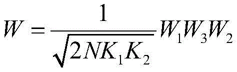
Alternatively, in one possible design, all antenna ports may be divided into N groups (N may be 2,4,8, etc.), with the number of CSI-RS ports of the horizontal dimension in each group being K 1 The number of CSI-RS ports in the vertical dimension is K 2 . For cross-polarized antennas, the total number of antenna ports is 2 x n x k 1 *K 2 . If the difference parameter of the block codebook is a phase difference, the structure of the precoding matrix in the codebook is specifically shown in the following formula 1.1:
W
3 from third PMIi
3,r R=1,..n-1 indicates that the third PMI may be a wideband PMI. For example θ
r =2πi
3,r X, X may be a value in the set {2,4,8, … }.
Representing a dimension of 2K
1 K
2 ×2K
1 K
2 Is a unit matrix of (a). W (W)
1 Indicated by the first PMI, which is a wideband PMI, <>
Representing a dimension K
1 K
2 X B, wherein each column corresponds to a DFT vector. W (W)
2 Indicated by the second PMI, which is a kind of subband PMI.
Is a vector of dimension B x 1 where the i-th element is 1 and the remaining elements are 0.
The phase difference between the two polarization directions of the antenna is represented, n represents a function of the second PMI, e represents a natural constant, j represents a unit imaginary number, and pi represents a circumference ratio.
In one possible design, all antenna ports may be divided into N groups (N may be 2,4,8, etc.), with the number of CSI-RS ports in the horizontal dimension in each group being K 1 The number of CSI-RS ports in the vertical dimension is K 2 Thus the total number of antenna ports is 2 x n x k 1 *K 2 (corresponding to dual polarized antennas). If the difference parameter of the block codebook is a phase difference, the structure of the precoding matrix in the codebook is specifically shown in the following formula 1.1:
W
3 from third PMIi
3,r R=1..n-1 indicates that the third PMI may be a wideband PMI or a subband PMI. For example θ
r =2πi
3,r X, X may be a value in the set {2,4,8, … }. I
2B Representing an identity matrix of dimension 2B x 2B. W (W)
1 Indicated by a first PMI, which is a wideband PMI,
representing a dimension K
1 K
2 X B, wherein each column corresponds to a DFT vector. W (W)
2 Indicated by the second PMI, which is a kind of subband PMI.
Is a vector of dimension B x 1 where the i-th element is 1 and the remaining elements are 0.
The phase difference between the two polarization directions of the antenna is represented, n represents a function of the second PMI, e represents a natural constant, j represents a unit imaginary number, and pi represents a circumference ratio.
In one possible design, all antenna ports may be divided into N groups (N may be 2,4,8, etc.), with the number of CSI-RS ports in the horizontal dimension in each group being K 1 The number of CSI-RS ports in the vertical dimension is K 2 Thus the total number of antenna ports is 2 x n x k 1 *K 2 (corresponding to dual polarized antennas). If the difference parameter of the block codebook is a phase difference, the structure of the precoding matrix in the codebook may be specifically as follows:
W
1 indicated by the first PMI, which may be a wideband PMI,
representing a dimension K
1 K
2 X B, wherein each column corresponds to a DFT vector. W (W)
2 Indicated by the second PMI, the second PMI may be a kind of subband PMI.
Is a vector of dimension B x 1 where the i-th element is 1 and the remaining elements are 0.
Represents the phase difference between the two polarization directions of the antenna, and n represents a function of the second PMI. θ
r =2πi
2,r X, r=1..n-1, X may be a value in the set {2,4,8, … }. e represents a natural constant, j represents a unit imaginary number, and pi represents a circumference ratio. />
Or:
W
1 indicated by the first PMI, which may be a wideband PMI,
representing a dimension K
1 K
2 X B, wherein each column corresponds to a DFT vector. W (W)
2 Indicated by the second PMI, which is a kind of subband PMI.
Is of dimension K
1 K
2 X 1, where the i-th element is 1 and the remaining elements are 0.
Represents the phase difference between the two polarization directions of the antenna, and n represents a function of the second PMI. W (W)
3 From third PMIi
3,r R=1..n-1 indicates that the third PMI may be a subband PMI. For example θ
r =2πi
3,r X, X may be a value in the set {2,4,8, … }. e represents a natural constant, j represents a unit imaginary number, and pi represents a circumference ratio.
In one possible design, all antenna ports are divided into N groups (N may be 2,4,8, etc.), with the number of CSI-RS ports in the horizontal dimension in each group being K 1 The number of CSI-RS ports in the vertical dimension is K 2 Thus the total number of antenna ports is 2 x n x k 1 *K 2 (corresponding to dual polarized antennas). Taking rank1 as an example, if the block codebook difference parameter is a phase difference, the structure of the precoding matrix in the codebook may be:
where N may represent the number of antenna port groups or the number of antenna panels. c 0,0,1 ,c 0,1,1 ,…,c N-1,0,1 ,c N-1,1,1 Indicating the phase factor or phase difference between the antenna port groups or the phase factor or phase difference between the antenna ports of different antenna panels or the phase factor or phase difference between the antenna ports of different polarization directions. c 0,0,1 ,c 0,1,1 ,…,c N - 1,0,1 ,c N-1,1,1 The first PMI, the second PMI, or the third PMI may be a function of the first PMI, the second PMI, or the third PMI. The first PMI is a wideband PMI, the second PMI is a subband PMI, and the third PMI may be a wideband PMI or a subband PMI. b l,m Representing a length K 1 *K 2 For example, can be the kronecker product of two 1-dimensional DFT vectors. l and m represent functions of a first PMI, which may be a wideband PMI.
For example
The structure of the precoding matrix in the codebook is specifically as shown in the following formula 1.1:
wherein,,
the phase difference or the phase factor between two polarization directions of the antenna is represented, wherein n represents a function of a second PMI, which can be a wideband PMI or a subband PMI, and takes on the value {0,1,2,3 }. Wherein e represents a natural constant, j represents a unit imaginary number, and pi represents a circumference ratio;
v
l Representing a length K
1 Of the DFT vector of (1), said K
1 The number of CSI-RS ports in the horizontal dimension in each group;
u
m Representing a length K
2 Of the DFT vector of (1), said K
2 The number of CSI-RS ports in the vertical dimension in each group; (θ)
1 … θ
N-1 ) Representing the phase difference parameter or phase factor between different antenna port groups, or referring to the phase difference parameter or phase factor between antenna panels, +.>
The value of (2) may be { +1, -1, +j, -j }; the O is
1 And said O
2 Represents an oversampling factor, said +.>
Representing the kronecker product. N may represent the number of antenna port groups or the number of antenna panels.
Similarly in a multi-panel codebook where rank is r, (where r may be equal to 2,3, 4), phases may be used between antenna port packets of different layersAs well as (theta) 1 … θ N-1 ). In the following embodiments, the description is omitted. For example, the structure of the rank 2 codebook may be:
Wherein->
Representing a precoding matrix corresponding to each antenna port group of the first data layer, +.>
Representing the precoding matrix corresponding to each antenna port group of the second data layer, the corresponding PMI feedback method is similar to rank 1.
Represents the phase difference between the two polarization directions of the antenna or, where n represents a function of the second PMI, takes on the value 0,1,2, 3. Wherein e represents a natural constant, j represents a unit imaginary number, and pi represents a circumference ratio;
v
l Representing a length K
1 Of the DFT vector of (1), said K
1 For the number of CSI-RS ports in the horizontal dimension in each packet, l=1, 2;
u
m representing a length K
2 Of the DFT vector of (1), said K
2 For the number of CSI-RS ports in the vertical dimension in each packet, m=1, 2; (θ)
1 … θ
N-1 ) Representing the phase difference parameter or phase factor between different antenna port groups, or referring to the phase difference parameter or phase factor between antenna panels, +.>
The value of (2) may be { +1, -1, +j, -j }; the O is
1 And said O
2 Represents an oversampling factor, said +.>
Representing the kronecker product. N may represent the number of antenna port groups or the number of antenna panels.
Alternatively, the codebook matrix structure of rank 1 may also be:
wherein the method comprises the steps of
v
l,m Representing a length K
1 ×K
2 The vector of K
1 The number of CSI-RS ports in the horizontal dimension in each packet. / >
u
m Representing a length K
2 Of the DFT vector of (1), said K
2 The number of CSI-RS ports in the vertical dimension in each packet. l and m represent functions of a first PMI, which may be a wideband PMI. Wherein (1)>
The phase difference between the two polarization directions of the antenna is represented, or n represents a function of a second PMI, which may be a wideband PMI or a subband PMI, and takes on a value {0,1,2,3 }. Wherein e represents a natural constant, j represents a unit imaginary number, and pi represents a circumference ratio; (θ)
1 … θ
N-1 ) Representing phase difference parameters or phase factors between different groups of antenna ports, or phase difference parameters or phase factors between antenna panels,
the value of (2) may be { +1, -1, +j, -j }; the O is
1 And said O
2 Represents an oversampling factor, said +.>
Representing the kronecker product. N may represent the number of antenna port groups or the number of antenna panels.
Accordingly, the rank 2 codebook matrix structure may be:
wherein the method comprises the steps of
Representing a precoding matrix corresponding to each antenna port group of the first data layer, +.>
Representing the precoding matrix corresponding to each antenna port group of the second data layer, the corresponding PMI feedback method is similar to rank 1.
v
l,m Representing a length K
1 K
2 The vector of K
1 For the number of CSI-RS ports in the horizontal dimension in each packet, l=1, 2, m=1, 2./ >
u
m Representing a length K
2 Of the DFT vector of (1), said K
2 For the number of CSI-RS ports in the vertical dimension in each packet, m=1, 2.l and m represent functions of a first PMI, which may be a wideband PMI. Wherein (1)>
Represents the phase difference between the two polarization directions of the antenna or, where n represents a function of the second PMI, takes on the value 0,1,2, 3. Wherein e represents a natural constant, j represents a unit imaginary number, and pi represents a circumference ratio; (θ)
1 … θ
N-1 ) Representing different antenna port divisionsPhase difference parameter or phase factor between groups, or phase difference parameter or phase factor between antenna panels, < ->
The value of (2) may be { +1, -1, +j, -j }; the O is
1 And said O
2 Represents an oversampling factor, said +.>
Representing the kronecker product. N may represent the number of antenna port groups or the number of antenna panels.
Or,
wherein (a) 1 ,…,a N ) Represents an amplitude factor of 0.ltoreq.a 1 ,…,a N ≤1。
1) Optionally, the PMI fed back to the base station by the user includes a first PMI, a second PMI and a third PMI, where the first PMI corresponds to two codebook indexes, and for convenience of explanation, the two codebook indexes are referred to as a first horizontal codebook index and a first vertical codebook index, the second PMI corresponds to the second codebook index, and the third PMI corresponds to the third codebook index. The value of n is indicated by the second codebook index, the value of m is indicated by the first vertical codebook index, or by the first vertical codebook index and the second codebook index, and the value of l is indicated by the first horizontal codebook index, or by the first horizontal codebook index and the second codebook index.
(θ 1 … θ N-1 ) May be indicated by a third codebook index, e.g., the third codebook index contains a plurality of values i 3,r ,r=1,…,N-1,θ r =2πi 3,r X, X may be a value in the set {2,4,8, … }. A specific example of the codebook when n=2 is given below:
or,
the first PMI is a wideband PMI, the second PMI is a subband PMI, and the third PMI may be a wideband PMI or a subband PMI.
2) Optionally, the PMI fed back to the base station by the user includes a first PMI and a second PMI, where the first PMI corresponds to two codebook indexes, and for convenience of explanation, the two codebook indexes are referred to as a first horizontal codebook index and a first vertical codebook index, and the second PMI corresponds to the second codebook index. The value of n is indicated by the second codebook index, the value of m is indicated by the first vertical codebook index, or by the first vertical codebook index and the second codebook index, and the value of l is indicated by the first horizontal codebook index, or by the first horizontal codebook index and the second codebook index. (θ) 1 … θ N-1 ) May be indicated by a first codebook index, one possible implementation being that the first codebook index contains N +2 values, one of which is i 1,1 For determining the value of i, another value i 1,2 For determining the value of m, the remaining N values are used for determining (θ 1 … θ N-1 ) For example, θ r =2πi 1,r+2 X r =1, …, N-1, x can be values in the set {2,4,8, … }. A specific example of the codebook when n=2 is given below:
or,
wherein the first PMI is a wideband PMI and the second PMI is a subband PMI.
3) In addition, (θ) 1 … θ N-1 ) May also be indicated by a second codebook index, e.g., the second codebook index contains n+1 values, one of which is i 2,N+1 For determining the phase difference between the antenna polarization directions (see fig. 1), other N values i2,r (with reference to fig. 3) for determining (with reference to fig. 4): (referring to FIG. 5), X may be a value in the set {2,4,8, … }. (refer to FIG. 5).
Or,
wherein the first PMI is a wideband PMI and the second PMI is a subband PMI. The magnitude factor example is similar.
In one possible design, the antenna may be a dual polarized antenna or a single polarized antenna, and each panel may have two polarization directions of the antenna at the same time, or may have only one polarization direction of the antenna (i.e., the two polarization directions of the antenna are distributed on two panels). In one possible design, all antenna ports are divided into N groups (N may be 2,4,8, etc.), e.g., each group corresponds to an antenna port of one polarization direction on one antenna panel. The number of CSI-RS ports in the horizontal dimension is K 1 The number of CSI-RS ports in the vertical dimension is K 2 Thus the total number of antenna ports is N x K 1 *K 2 . If the difference parameter of the block codebook is a phase difference, the structure of the precoding matrix in the rank 1 codebook is specifically as follows:
wherein the method comprises the steps of
v
l Representing a length K
1 DFT vectors of (2)Amount of said K
1 The number of CSI-RS ports in the horizontal dimension in each group;
u
m Representing a length K
2 Of the DFT vector of (1), said K
2 The number of CSI-RS ports in the vertical dimension in each group; the l is a function of the first horizontal codebook index and has a corresponding relation with the first PMI, and the m is a function of the first vertical codebook index and has a corresponding relation with the first PMI. The O is
1 And said O
2 Represents an oversampling factor, said +.>
Representing the kronecker product. Wherein e represents a natural constant, j represents a unit imaginary number, and pi represents a circumference ratio; (θ)
1 … θ
N-1 ) Representing phase difference parameters or phase factors between different groups of antenna ports, or representing phase factors between antenna ports of different polarization directions, or referring to phase difference parameters or phase factors between antenna panels, +.>
The value of (2) may be { +1, -1, +j, -j }; n may represent the number of antenna port groups or the number of antenna panels.
The precoding matrix structure in the rank 2 codebook may be
Wherein the method comprises the steps of
Representing a precoding matrix corresponding to each antenna port group of the first data layer, +.>
Representing a precoding matrix corresponding to each antenna port group of the second data layer, corresponding PMThe I feedback method is similar to rank 1.
v
l Representing a length K
1 Of the DFT vector of (1), said K
1 For the number of CSI-RS ports in the horizontal dimension in each packet, l=1, 2;
u
m Representing a length K
2 Of the DFT vector of (1), said K
2 For the number of CSI-RS ports in the vertical dimension in each packet, m=1, 2; the l is a function of a first horizontal codebook index and has a corresponding relation with a first PMI, the m is a function of a first vertical codebook index and has a corresponding relation with the first PMI, and the first PMI may be a wideband PMI. The O is
1 And said O
2 Represents an oversampling factor, said +.>
Representing the kronecker product. Wherein e represents a natural constant, j represents a unit imaginary number, and pi represents a circumference ratio; (θ)
1 … θ
N-1 ) Representing phase difference parameters or phase factors between different groups of antenna ports, or representing phase factors between antenna ports of different polarization directions, or referring to phase difference parameters or phase factors between antenna panels, +.>
The value of (2) may be { +1, -1, +j, -j }; n may represent the number of antenna port groups or the number of antenna panels.
Or the structure of the precoding matrix in the rank 1 codebook can be
Wherein the method comprises the steps of
v
l,m Representing a length K
1 K
2 The vector of K
1 The number of CSI-RS ports in the horizontal dimension in each group;
u
m Representing a length K
2 Of the DFT vector of (1), said K
2 The number of CSI-RS ports in the vertical dimension in each packet. The O is
1 And said O
2 And representing an oversampling factor, wherein l is a function of a first horizontal codebook index and has a corresponding relation with a first PMI, the first PMI can be a wideband PMI, and m is a function of a first vertical codebook index and has a corresponding relation with the first PMI. The O is
1 And said O
2 Represents an oversampling factor, said +.>
Representing the kronecker product. Wherein e represents a natural constant, j represents a unit imaginary number, and pi represents a circumference ratio; (θ)
1 … θ
N-1 ) Representing the phase difference parameter or phase factor between different groups of antenna ports, or representing the phase factor between antenna ports of different polarization directions, or referring to the phase difference parameter or phase factor between antenna panels,
the value of (2) may be { +1, -1, +j, -j }; n may represent the number of antenna port groups or the number of antenna panels.
The structure of the precoding matrix in the rank 2 codebook may be
Wherein the method comprises the steps of
Representing a precoding matrix corresponding to each antenna port group of the first data layer, +. >
Representing the precoding matrix corresponding to each antenna port group of the second data layer, the corresponding PMI feedback method is similar to rank 1. The l is a function of the first horizontal codebook index and has a corresponding relation with the first PMI, and the m is a function of the first vertical codebook index and has a corresponding relation with the first PMI. The O is
1 And said O
2 Represents an oversampling factor, said +.>
Representing the kronecker product. Wherein e represents a natural constant, j represents a unit imaginary number, and pi represents a circumference ratio; (θ)
1 … θ
N-1 ) Representing phase difference parameters or phase factors between different groups of antenna ports, or representing phase factors between antenna ports of different polarization directions, or referring to phase difference parameters or phase factors between antenna panels, +.>
The value of (2) may be { +1, -1, +j, -j }; n may represent the number of antenna port groups or the number of antenna panels.
Or alternatively
Wherein (a) 1 ,…,a N ) Represents an amplitude factor of 0.ltoreq.a 1 ,…,a N ≤1。
Optionally, the PMI fed back to the base station by the user includes a first PMI and a second PMI, where the first PMI corresponds to two codebook indexes, and for convenience of explanation, the two codebook indexes are referred to as a first horizontal codebook index and a first vertical codebook index, and the second PMI corresponds to the second codebook index. The value of n is indicated by the second codebook index, the value of m is indicated by the first vertical codebook index, or by the first vertical codebook index and the second codebook index, and the value of l is indicated by the first horizontal codebook index, or by the first horizontal codebook index and the second codebook index.
(θ
1 … θ
N-1 ) Representing a difference parameter, such as a phase difference, between different antenna port groupings; (θ)
1 … θ
N-1 ) May be determined by a second codebook index, e.g., the second codebook index contains a plurality of values i
2,r ,r=1,…,N-1,θ
r =2πi
2,r X, X may be a value in the set {2,4,8, … }. (θ)
1 … θ
N-1 ) All or part of the values in (a) may also be determined by a first codebook index, e.g. a first codebook index containing a plurality of values i
1,r ,r=1,…,N-1,θ
r =2πi
2,r X, X may be a value in the set {2,4,8, … }. Alternatively, (θ)
1 … θ
N-1 ) The whole or part of the values in (a) may be determined by the first PMI and the second PMI. For example, θ
i =a
i ·b
i Wherein
a
i Determined by the first PMI, b
i Is determined by the second PMI.
A specific example of the codebook when n=4 is given below:
or,
wherein the first PMI i 1,1 And i 1,2 Is a wideband PMI, a second PMI i 2,1 ,i 2,2 ,i 2,3 ,i 2,4 Is a subband PMI, or a wideband PMI in which a part of values is a wideband PMI and a subband PMI in which another part of values is a subband PMI. The magnitude factor example is similar.
In one possible implementation manner, if the difference parameter of the block codebook is a phase difference, the structure of the precoding matrix in the codebook is specifically as shown in the following formula 1.1:
optionally, the formula may also be:
wherein (1)>
Representing the phase difference between the two polarization directions of the antenna;
Optionally, also
The v is
l,θ N representing the horizontal dimension
1 Precoding matrixes in the codebooks are obtained by transforming parameter values corresponding to the difference parameters of the block codebooks; above->
v
l Representing each block codebook consisting of a length K
1 Is a vector component of the K
1 For the number of CSI-RS ports corresponding to each block codebook in the horizontal dimension, θ represents the phase difference parameter in the horizontal dimension, +.>
Representing the phase difference between precoding vectors in different block codebooks in the horizontal dimension;
Optionally, also +.>
u
m,φ N representing the vertical dimension
2 Precoding in the codebook, which is obtained by transforming parameter values corresponding to difference parameters of the block codebooksMatrix (S)>
u
m Representing each block codebook consisting of a length K
2 Is a vector component of the K
2 The number of CSI-RS ports corresponding to each codebook in the vertical dimension is calculated; phi represents the phase difference parameter in the vertical dimension (phi)
1 … φ
N2 ) Representing the phase difference between precoding matrices in different block codebooks of the vertical dimension; the O is
1 And said O
2 Representing an oversampling factor, wherein l, m and n are functions of codebook indexes, the codebook indexes and the PMI have corresponding relations, j is an imaginary number, and +.>
Representing the kronecker product.
Or alternatively
(except for not indicating (phi)
1 ,φ
2 …φ
n ) The latter PMI indication method is similar and is omitted here without writing
Wherein the method comprises the steps of
v
l Representing a length K
1 Of the DFT vector of (1), said K
1 The number of CSI-RS ports in the horizontal dimension in each group;
u
m Representing a length K
2 Of the DFT vector of (1), said K
2 The number of CSI-RS ports for the vertical dimension in each packet is or +>
(except for not indicating (phi)
1 ,φ
2 …φ
n ) The latter PMI indication method is similar and is omitted here without writing
Wherein the method comprises the steps of
v
l,m Representing a length K
1 K
2 The vector of K
1 The number of CSI-RS ports in the horizontal dimension in each group;
Representing a length K
2 Of the DFT vector of (1), said K
2 The number of CSI-RS ports in the vertical dimension in each packet. The O is
1 And said O
2 Representing the oversampling factor.
In this possible implementation, the manner in which the PMI indicates the phase difference may be divided into the following possible manners.
Mode one: the PMI includes a first PMI and a second PMI, wherein the first PMI corresponds to two codebook indexes, and for convenience of explanation, the two codebook indexes are referred to as a first horizontal codebook index and a first vertical codebook index, and the second PMI corresponds to the second codebook index. Phase difference
Indicated by the first horizontal codebook index, the phase difference (phi
1 … φ
N2 ) Indicated by the first vertical codebook index. Optionally, the value of n is indicated by a second codebook index, the value of m is indicated by a first vertical codebook index and a second codebook index, and the value of l is indicated by a first horizontal codebook index and a second codebook index.
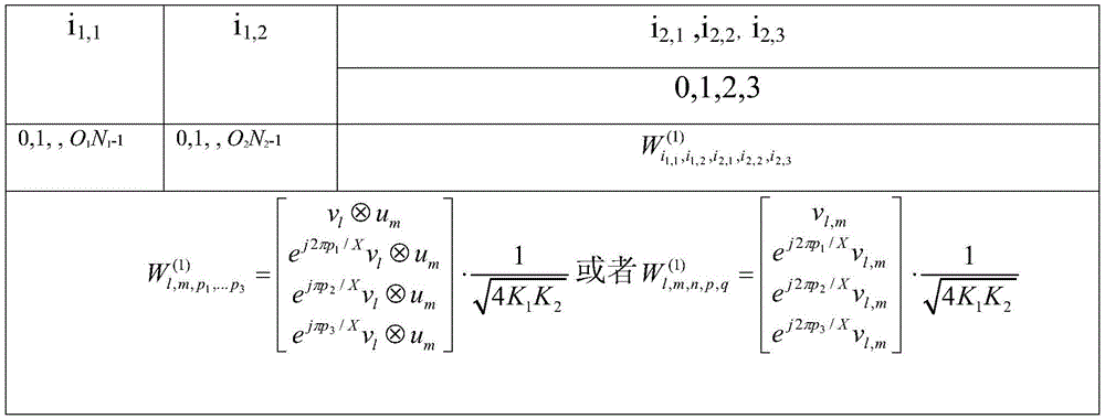
The relationship between l, m, n will be described by taking a specific example as an example. See table one for details.
List one
In Table I, i 1,1 Representing a first horizontal codebook index, i 1,2 Representing a first vertical codebook index, i 2 Representing a second codebook index, i 1,1 And i 1,2 The specific value of (2) is not particularly limited herein. When i 2 When =2, l=2i 1,1 ,m=2i 1,2 N=2; when i 2 When=6, l=2i 1,1 +1,m=2i 1,2 N=2; when i 2 When =10, l=2i 1,1 ,m=2i 1,2 +1,n=2。
Those skilled in the art will understand that the following relationships between l, m, n and the manner of determining the values of l, m, n are similar to those of the present embodiment, and thus will not be described in detail.
Mode two: the PMI includes a first PMI and a second PMI, wherein the first PMI corresponds to two codebook indexes, and for convenience of explanation, the two codebook indexes are referred to as a first horizontal codebook index and a first vertical codebook index, and the second PMI corresponds to the second codebook index. n, phase difference (phi)
1 … φ
N2 ) And phase difference
The value of (2) is indicated by the second codebook index. The value of m is indicated by a first vertical codebook index and a second codebook index, and the value of l is indicated by a first horizontal codebook index and a second codebook index.
Alternatively, the value of the second PMI may also correspond to two codebook indexes, which are referred to as a second horizontal codebook index and a second vertical codebook index for convenience of explanation. Phase difference (phi)
1 … φ
N2 ) Indicated by the second vertical codebook index,
indicated by the second horizontal codebook index, and the value of n is indicated by the second vertical codebook index and the second horizontal codebook index. The value of m is indicated by a first vertical codebook index and a second vertical codebook index, and the value of l is indicated by a first horizontal codebook index and a second horizontal codebook index.
Mode three: the PMI comprises a first PMI, a second PMI and a third PMI, wherein the first PMI corresponds to two codebook indexes, the two codebook indexes are called a first horizontal codebook index and a first vertical codebook index for convenience of explanation, the second PMI corresponds to the second codebook index, and the third PMI corresponds to the third codebook indexThis index. Phase difference (phi)
1 … φ
N2 ) And
the value of (2) is indicated by a third codebook index. Optionally, the value of n is indicated by a second codebook index. The value of m is indicated by a first vertical codebook index and a second codebook index, and the value of l is indicated by a first horizontal codebook index and a second codebook index. Alternatively, for example, the third codebook index contains a plurality of values i
3,r ,r=1,…,N
1 -1, i
3,s ,s=1,…,N
2 -1, wherein θ
r =2πi
3,r /X,φ
s =2πi
3,s XX may be a value in the set {2,4,8 }; the first PMI is a wideband PMI, the second PMI is a subband PMI, and the third PMI may be a wideband PMI or a subband PMI.
Alternatively, the third PMI may also correspond to two codebook indexes, which are referred to as a third vertical codebook index and a third horizontal codebook index for convenience of explanation. At this time, (phi)
1 … φ
N2 ) The value of (c) is indicated by a third vertical codebook index,
the value of (2) is indicated by a third horizontal codebook index.
Optionally, for example, the third horizontal codebook index comprises a plurality of values
r=1,…,N
1 -1,
X may be a value in the set {2,4,8, … }; the third vertical codebook index contains a plurality of values +.>
r=1,…,N
2 -1,
X may be in the set {2,4,8}Is a value of (2). The first PMI is a wideband PMI, the second PMI is a subband PMI, and the third PMI may be a wideband PMI or a subband PMI. On the UE side, the UE can estimate the channel from the reference signal and determine +.>
And
the value and the codebook index of the PMI are fed back to the base station, and the codebook index corresponding to the PMI is acquired at the base station side to obtain +.>
According to the value of (2)
Value sum of>
A target precoding matrix may be obtained.
In another possible implementation manner, if the block codebook difference parameter is a module value difference, the structure of the precoding matrix in the codebook is specifically as shown in the following formula 1.2:
if the difference parameter of the block codebook is a module value difference, the structure of the precoding matrix in the codebook is specifically shown in the following formula 1.2:
Equation 1.2, alternatively, the equation may be:
wherein,,
representing the space between the two polarization directions of the antennaA phase difference; v
l,β =[v
l β
1 v
l … β
N1 v
l ]Alternatively, it may be +>
The v is
l,β N representing the horizontal dimension
1 Precoding matrixes in the codebooks are obtained by transforming parameter values corresponding to the difference parameters of the block codebooks;
v
l Representing each block codebook consisting of a length K
1 Is a vector component of the K
1 For the number of CSI-RS ports corresponding to each block codebook in the horizontal dimension, beta represents the modulus difference parameter in the horizontal dimension, and +.>
Representing a modular value difference between precoding matrices in different block codebooks of a horizontal dimension;
Alternatively, it may be
u
m,α N representing the vertical dimension
2 N corresponding to block codebooks
2 A DFT vector;
u
m Representing each block codebook consisting of a length K
2 Is composed of DFT vectors of said K
2 The number of CSI-RS ports corresponding to each block codebook in the vertical dimension is set; alpha represents a modulus difference parameter of the vertical dimension;
a modulus difference between precoding vectors in different block codebooks representing the vertical dimension; the O is
1 And said O
2 Representing an oversampling factor, said l, m, n being a function of the codebook index, saidCodebook indices have a correspondence with the PMIs, where j is the unit imaginary number, and +. >
Representing the kronecker product.
In this possible implementation, the mode value difference is indicated by the PMI, and may be classified into the following possible implementations.
Mode one: the PMI includes a first PMI and a second PMI, wherein the first PMI corresponds to two codebook indexes, and for convenience of explanation, the two codebook indexes are referred to as a first horizontal codebook index and a first vertical codebook index, and the second PMI corresponds to the second codebook index. Difference of modulus
Indicated by the first horizontal codebook index, modulo difference +.>
Indicated by the first vertical codebook index. Optionally, the value of n is indicated by a second codebook index, the value of m is indicated by a first vertical codebook index and a second codebook index, and the value of l is indicated by a first horizontal codebook index and a second codebook index.
Mode two: the PMI includes a first PMI and a second PMI, wherein the first PMI corresponds to two codebook indexes, and for convenience of explanation, the two codebook indexes are referred to as a first horizontal codebook index and a first vertical codebook index, and the second PMI corresponds to the second codebook index. n is a number of the total number of the n,
and->
The value of (2) is indicated by the second codebook index. The value of m is indicated by a first vertical codebook index and a second codebook index, and the value of l is indicated by a first horizontal codebook index and a second codebook index.
Alternatively, the value of the second PMI may also correspond to two codebook indices, which are provided for convenience of explanationThe codebook indices are referred to as a second horizontal codebook index and a second vertical codebook index.
Indicated by the second vertical codebook index, is->
Indicated by the second horizontal codebook index, and the value of n is indicated by the second vertical codebook index and the second horizontal codebook index. The value of m is indicated by a first vertical codebook index and a second vertical codebook index, and the value of l is indicated by a first horizontal codebook index and a second horizontal codebook index.
Mode three: the PMI includes a first PMI, a second PMI, and a third PMI, wherein the first PMI corresponds to two codebook indexes, and for convenience of explanation, the two codebook indexes are referred to as a first horizontal codebook index and a first vertical codebook index, the second PMI corresponds to the second codebook index, and the third PMI corresponds to the third codebook index.
And->
The value of (2) is indicated by a third codebook index. Optionally, the value of n is indicated by a second codebook index. The value of m is indicated by a first vertical codebook index and a second codebook index, and the value of l is indicated by a first horizontal codebook index and a second codebook index.
Alternatively, the third PMI may also correspond to two codebook indexes, which are referred to as a third vertical codebook index and a third horizontal codebook index for convenience of explanation. At this time, the liquid crystal display device,
The value of (2) is indicated by the third vertical codebook index, is->
The value of (2) is indicated by a third horizontal codebook index.
On the UE side, the UE can estimate the channel based on the reference signal and determine based thereon
And
the value and the codebook index of the PMI are fed back to the base station, and the codebook index corresponding to the PMI is acquired at the base station side to obtain +.>
According to>
Value sum of>
A target precoding matrix may be obtained.
Next, the structure of the precoding matrix in the codebook will be described when the vector corresponding to each block codebook is a vector corresponding to a beam of a different transmission angle. Fig. 5 is a schematic diagram of an antenna panel and a beam according to an embodiment of the present invention. As shown in fig. 5, the vectors corresponding to the respective block codebooks may be DFT vectors corresponding to the beams of the same transmission angle or DFT vectors corresponding to the beams of different transmission angles, and the DFT vectors corresponding to the respective block codebooks are synthesized into DFT vectors corresponding to the transmission beams by splicing or the like.
In one possible implementation, if the difference parameter of the block codebook is a phase difference, the structure of the precoding matrix in the codebook is as shown in formula 1.3:
equation 1.3, optionally, may also be:
wherein,,
representing the phase difference between the two polarization directions of the antenna; / >
l=l
1 …l
N1 The method comprises the steps of carrying out a first treatment on the surface of the Optionally, also +.>
The v is
l,θ N representing the horizontal dimension
1 Precoding matrix in the codebook, which is obtained by transforming parameter values corresponding to difference parameters of the block codebooks and the block codebooks, is +.>
v
l Representing each block codebook consisting of a length K
1 Is a vector component of the K
1 For the number of CSI-RS ports corresponding to each block codebook in the horizontal dimension, θ represents the phase difference parameter in the horizontal dimension,
representing phase differences between precoding matrices in different block codebooks in the horizontal dimension;
alternatively, it is also possible to
u
m,φ N representing the vertical dimension
2 Precoding matrixes in the codebooks are obtained by transforming parameter values corresponding to the difference parameters of the block codebooks;
u
m representing each block codebook consisting of a length K
2 Is composed of the vectors of (1)The K is
2 The number of CSI-RS ports corresponding to each codebook in the vertical dimension is calculated; phi represents the phase difference parameter in the vertical dimension (phi)
1 … φ
N2 ) Representing the phase difference between precoding matrices in different block codebooks of the vertical dimension; the O is
1 And said O
2 Representing an oversampling factor, wherein l, m and n are functions of codebook indexes, the codebook indexes and the PMI have corresponding relations, j is an imaginary number, and +.>
Representing the kronecker product.
In this possible implementation, the manner in which the PMI indicates the phase difference may be divided into the following possible manners.
Mode one: the PMI includes a first PMI and a second PMI, wherein the first PMI corresponds to two codebook indexes, and for convenience of explanation, the two codebook indexes are referred to as a first horizontal codebook index and a first vertical codebook index, and the second PMI corresponds to the second codebook index. (phi)
1 … φ
N2 ) Indicated by the first vertical codebook index,
indicated by the first horizontal codebook index. Optionally, the value of n is indicated by a second codebook index.
Indicated collectively by the first vertical codebook index and the second codebook index.
Indicated collectively by the first horizontal codebook index and the second codebook index. Alternatively, it may also be:
indicated collectively by the first vertical codebook index and the second codebook index.
Indicated collectively by the first horizontal codebook index and the second codebook index.
Alternatively, the first PMI may also correspond to a first horizontal codebook index, a differential first horizontal codebook index, a first vertical codebook index, and a differential first vertical codebook index. (phi)
1 … φ
N2 ) Indicated by the first vertical codebook index,
the value of (2) is indicated by a first horizontal codebook index. Optionally, the value of n is indicated by a second codebook index. At this time, a->
Should have a predetermined functional relationship (e.g. linear relationship) between them and indicated by a first vertical codebook index, a differential first vertical codebook index and a second codebook index, < > >
There should also be a predetermined functional relationship (e.g., linear relationship) between them, and indicated by the first horizontal codebook index, the differential first horizontal codebook index, and the second codebook index. Alternatively, it may also be:
Should have a predetermined functional relationship (e.g. linear relationship) between them and indicated by a first vertical codebook index, a differential first vertical codebook index and a second codebook index, < >>
There should also be a predetermined functional relationship (e.g., linear relationship) between them, and indicated by the first horizontal codebook index, the differential first horizontal codebook index, and the second codebook index.
Mode two: the PMI includes a first PMI and a second PMI, wherein the first PMI corresponds to two codebook indexes, and for convenience of explanation, the two codebook indexes are referred to as a first horizontal codebook index and a first vertical codebook index, and the second PMI corresponds to the second codebook index. n, (phi)
1 … φ
N2 ) And
the value of (2) is indicated by the second codebook index.
Indicated jointly by the first vertical codebook index and the second codebook index.
Indicated jointly by the first horizontal codebook index and the second codebook index. Alternatively, it can also be +.>
Indicated jointly by the first vertical codebook index and the second codebook index.
Indicated jointly by the first horizontal codebook index and the second codebook index.
Alternatively, the value of the second PMI may also correspond to two codebook indexes, which are referred to as a second horizontal codebook index and a second vertical codebook index for convenience of explanation. (phi)
1 … φ
N2 ) Indicated by the second vertical codebook index,
indicated by the second horizontal codebook index, the value of n is indicated by the second vertical codebook index and the second horizontal codebook index together.
Indicated jointly by the first vertical codebook index and the second vertical codebook index.
Indicated by the first horizontal codebook index and the second horizontal codebook index together. Alternatively, it can also be +.>
Indicated jointly by the first vertical codebook index and the second vertical codebook index.
Indicated by the first horizontal codebook index and the second horizontal codebook index together
Mode three: the PMI includes a first PMI, a second PMI, and a third PMI, wherein the first PMI corresponds to two codebook indexes, and for convenience of explanation, the two codebook indexes are referred to as a first horizontal codebook index and a first vertical codebook index, the second PMI corresponds to the second codebook index, and the third PMI corresponds to the third codebook index. The value of n is indicated by the second codebook index.
Indicated by the first vertical codebook index, the second codebook index and the third codebook index together. / >
Indicated by the first horizontal codebook index, the second codebook index and the third codebook index together. (phi)
1 … φ
N2 ) And->
Indicated by a third codebook index. Alternatively, it can also be +.>
Indicated by the first vertical codebook index, the second codebook index and the third codebook index together.
Indicated by the first horizontal codebook index, the second codebook index and the third codebook index together. (phi)
1 … φ
N2 ) And->
Indexed by the third codebookTo indicate.
Optionally, the third PMI may also correspond to a third vertical codebook index and a third horizontal codebook index. At this time, (phi)
1 … φ
N2 ) Indicated by the third vertical codebook index,
indicated by a third horizontal codebook index.
The first vertical codebook index, the second codebook index and the third vertical codebook index are collectively indicated.
The first, second and third horizontal codebook indices are indicated together. Alternatively, it may also be:
the first vertical codebook index, the second codebook index and the third vertical codebook index are collectively indicated.
The first, second and third horizontal codebook indices are indicated together.
On the UE side, the UE can estimate the channel based on the reference signal and determine based thereon
And
The value and the codebook index of the PMI are fed back to the base station, and the codebook index corresponding to the PMI is acquired at the base station side to obtain +.>
According to>
Value sum of>
A target precoding matrix may be obtained.
Alternatively, it may also be: on the UE side, the UE can estimate the channel based on the reference signal and determine based thereon
And
(φ
1 … φ
N2 ),
and the value of n and the codebook index, then feeding back the PMI corresponding to the codebook index to the base station, and obtaining the codebook index corresponding to the PMI at the base station side to obtain
(φ
1 … φ
N2 )
And n, according to the values of
(φ
1 … φ
N2 ),
And the sum of the values of n->
A target precoding matrix may be obtained.
In another possible implementation, if the block codebook difference parameter is a module value difference, the structure of the precoding matrix in the codebook is as shown in formula 1.4:
equation 1.4, optionally, may also be: />
Wherein,,
representing the phase difference between the two polarization directions of the antenna;
Optionally, also +.>
The v is
l,β N representing the horizontal dimension
1 Precoding matrixes in the codebooks are obtained by transforming parameter values corresponding to the difference parameters of the block codebooks;
l=l
1 …l
N1 optionally, also +.>
v
l Representing each block codebook consisting of a length K
1 Is a vector component of the K
1 For the number of CSI-RS ports corresponding to each block codebook in the horizontal dimension, beta represents a modulus difference parameter in the horizontal dimension, +. >
Representing a modular value difference between precoding matrices in different block codebooks of a horizontal dimension;
Alternatively, it is also possible to
u
m,α N representing the vertical dimension
2 Precoding matrixes in the codebooks are obtained by transforming parameter values corresponding to the difference parameters of the block codebooks;
u
m representing that each block codebook consists of a length K
2 Is a vector component of the K
2 The number of CSI-RS ports corresponding to each block codebook in the vertical dimension is set; alpha represents a modulus difference parameter of the vertical dimension;
a modulus difference between precoding matrices in different block codebooks representing the vertical dimension; the O is
1 And said O
2 Representing an oversampling factor, wherein l, m and n are functions of codebook indexes, the codebook indexes and the PMI have corresponding relations, j is an imaginary number, and +.>
Representing the kronecker product.
In this possible implementation, the mode value difference is indicated by the PMI, and may be classified into the following possible modes.
Mode one: the PMI includes a first PMI and a second PMI, wherein the first PMI corresponds to two codebook indexes, and for convenience of explanation, the two codebook indexes are referred to as a first horizontal codebook index and a first vertical codebook index, and the second PMI corresponds to the second codebook index.
Indicated by the first vertical codebook index, is- >
Indicated by the first horizontal codebook index. Optionally, the value of n is indicated by a second codebook index.
From a first droopThe direct codebook index and the second codebook index are indicated together.
Indicated collectively by the first horizontal codebook index and the second codebook index. Alternatively, it may also be:
indicated collectively by the first vertical codebook index and the second codebook index.
Indicated collectively by the first horizontal codebook index and the second codebook index.
Alternatively, the first PMI may also correspond to a first horizontal codebook index, a differential first horizontal codebook index, a first vertical codebook index, and a differential first vertical codebook index.
Indicated by the first vertical codebook index,
the value of (2) is indicated by a first horizontal codebook index. Optionally, the value of n is indicated by a second codebook index. At this time, a->
Should have a predetermined functional relationship (e.g. linear relationship) between them and indicated by a first vertical codebook index, a differential first vertical codebook index and a second codebook index, < >>
There should also be a predetermined functional relationship (e.g., linear relationship) between them, and indicated by the first horizontal codebook index, the differential first horizontal codebook index, and the second codebook index. Alternatively, it may also be:
With a predetermined function switch Is (e.g., linear) and is indicated by a first vertical codebook index, a differential first vertical codebook index and a second codebook index, +.>
There should also be a predetermined functional relationship (e.g., linear relationship) between them, and indicated by the first horizontal codebook index, the differential first horizontal codebook index, and the second codebook index.
Mode two: the PMI includes a first PMI and a second PMI, wherein the first PMI corresponds to two codebook indexes, and for convenience of explanation, the two codebook indexes are referred to as a first horizontal codebook index and a first vertical codebook index, and the second PMI corresponds to the second codebook index. n is a number of the total number of the n,
and->
The value of (2) is indicated by the second codebook index.
Indicated jointly by the first vertical codebook index and the second codebook index.
The first horizontal codebook index and the second codebook index are indicated in common. Alternatively, it may also be:
Indicated jointly by the first vertical codebook index and the second codebook index.
The first horizontal codebook index and the second codebook index are indicated in common.
Alternatively, the value of the second PMI may also correspond to two codebook indexes, which are referred to as a second horizontal codebook index and a second vertical codebook index for convenience of explanation.
Indicated by the second vertical codebook index, is- >
Indicated by the second horizontal codebook index, the value of n is indicated by the second vertical codebook index and the second horizontal codebook index together.
Indicated jointly by the first vertical codebook index and the second vertical codebook index.
Indicated by the first horizontal codebook index and the second horizontal codebook index together. Alternatively, it may also be:
indicated jointly by the first vertical codebook index and the second vertical codebook index.
Indicated by the first horizontal codebook index and the second horizontal codebook index together.
Mode three: the PMI includes a first PMI, a second PMI, and a third PMI, wherein the first PMI corresponds to two codebook indexes, and for convenience of explanation, the two codebook indexes are referred to as a first horizontal codebook index and a first vertical codebook index, the second PMI corresponds to the second codebook index, and the third PMI corresponds to the third codebook index. The value of n is indicated by the second codebook index.
Indicated by the first vertical codebook index, the second codebook index and the third codebook index together.
Indexed by a first horizontal codebook, a second codebook index and a third codebook indexAnd are collectively indicated by the references.
And->
Indicated by a third codebook index. Alternatively, it may also be:
Indicated by the first vertical codebook index, the second codebook index and the third codebook index together. / >
Indicated by the first horizontal codebook index, the second codebook index and the third codebook index together.
And->
Indicated by a third codebook index. />
Optionally, the third PMI may also correspond to a third vertical codebook index and a third horizontal codebook index. At this time, the liquid crystal display device,
indicated by the third vertical codebook index, is->
Indicated by a third horizontal codebook index.
The first vertical codebook index, the second codebook index and the third vertical codebook index are collectively indicated.
The first horizontal codebook index, the second codebook index and the third horizontal codebook index are commonly referred to asShown.
On the UE side, the UE can estimate the channel based on the reference signal and determine based thereon
And
the value and the codebook index of the PMI are fed back to the base station, and the codebook index corresponding to the PMI is acquired at the base station side to obtain +.>
According to>
Value sum of>
A target precoding matrix may be obtained.
Alternatively, it may also be:
the first vertical codebook index, the second codebook index and the third vertical codebook index are collectively indicated.
The first, second and third horizontal codebook indices are indicated together. On the UE side, the UE can estimate the channel from the reference signal and determine +. >
And
and the value of n and the codebook index, then feeding back the PMI corresponding to the codebook index to the base station, and obtaining the codebook index corresponding to the PMI at the base station side to obtain
And n, according to the values of
And the sum of the values of n->
A target precoding matrix may be obtained.
Those skilled in the art will appreciate that in the above embodiments, the correspondence between PMI and codebook index, and various indications of codebook index, are merely illustrative of some specific examples. In a specific implementation process, on the basis of the foregoing embodiment, there may also be multiple implementation manners, which are not described herein.
In this embodiment, the vectors corresponding to the respective block codebooks are weight vectors corresponding to a plurality of different angularly adjacent beams. Fig. 6 is a schematic diagram III of an antenna panel and a beam according to an embodiment of the present invention. As shown in fig. 6, DFT vectors corresponding to each block codebook may be DFT vectors corresponding to beams of the same transmission angle or DFT vectors corresponding to beams of different transmission angles, and DFT vectors corresponding to each block codebook are synthesized into DFT vectors corresponding to transmission beams by splicing or the like.
At this time, the structure of the precoding matrix in the codebook is specifically as shown in the following equation 2.9.
Wherein the method comprises the steps of
Indicating the phase difference between the two polarization directions of the antenna,
l=l
1 ,...,l
K ,l
1 ′,...,l′
K representing the DFT weighted basis vector.
Representing the weighting weights, K, of the different beam components
1 K is the number of CSI-RS ports corresponding to each block codebook in the horizontal dimension
2 For the number of CSI-RS ports corresponding to each block codebook in the vertical dimension, O
1 And O
2 Representing the oversampling factor, a function of the codebook indices of l, m, n.
According to the codebook-based channel state information feedback method provided by the embodiment of the invention, under the multi-panel antenna structure, the beam directivity can be ensured, and the system performance can be improved relative to the existing codebook. The design is simple, and the structural characteristics of the DFT codebook can be ensured. The codebook is generated through the codebook configuration parameters, so that the method has better expandability.
Table two shows the performance comparison of the codebook in an 8 antenna scenario, with 8 antennas divided into two groups of 4 antennas each. The inter-group antenna spacing is 0.5 times the wavelength and the inter-group antenna spacing is 8 times the wavelength. The DFT codebook is an LTE R10 codebook, and Advanced codebook (Advanced CB) shows a codebook scheme of phase compensation+adjacent beam selection proposed in the embodiment of the present invention, i.e. an embodiment corresponding to fig. 5. As can be seen from Table II, the codebook proposed by the embodiment of the present invention has an obvious performance gain relative to the existing codebook.
Watch II
| Signal to noise ratio
|
3
|
7
|
11
|
15
|
19
|
23
|
| R10 codebook
|
8.4977
|
12.3307
|
17.2316
|
20.7689
|
22.8085
|
23.6347
|
| Advanced CB
|
9.1604
|
13.3258
|
18.877
|
22.2036
|
24.4787
|
25.1669
|
| Gain of
|
7.79%
|
8.07%
|
9.55%
|
6.90%
|
7.32%
|
6.48% |
The scheme provided by the embodiment of the invention is mainly introduced from the interaction point of the TRP and the user equipment. It will be appreciated that TRP, user equipment, in order to achieve the above described functions, comprise corresponding hardware structures and/or software modules performing the respective functions. The various illustrative units and algorithm steps described in connection with the embodiments disclosed herein may be implemented as hardware or a combination of hardware and computer software. Whether a function is implemented as hardware or computer software driven hardware depends upon the particular application and design constraints imposed on the solution. Those skilled in the art may implement the described functionality using different approaches for each particular application, but such implementation is not to be considered as beyond the scope of the embodiments of the present invention.
The embodiment of the invention can divide the function units of the TRP and the user equipment according to the method example, for example, each function unit can be divided corresponding to each function, and two or more functions can be integrated in one processing unit. The integrated units may be implemented in hardware or in software functional units. It should be noted that, in the embodiment of the present invention, the division of the units is schematic, which is merely a logic function division, and other division manners may be implemented in actual practice.
In the case of adopting centralized units, fig. 7 is a schematic structural diagram of a user equipment according to an embodiment of the present invention. As shown in fig. 7, the user equipment 100 includes: a processing unit 12 and a communication unit 13. The processing unit 12 is configured to control and manage actions of the user equipment, for example, the processing unit 12 may determine the target precoding matrix in a pre-generated codebook. The communication unit 13 is configured to support communication between the user equipment and the TRP, for example, to transmit PMI to the TRP, and to receive codebook configuration parameters transmitted by the TRP. The user equipment may further comprise a storage unit 11 for storing program code and data of the user equipment.
The processing unit 12 may be a processor, such as a central processing unit (Central Processing Unit, CPU), a general purpose processor, a digital signal processor (Digital Signal Processor, DSP), an Application-specific integrated circuit (ASIC), a field programmable gate array (Field Programmable Gate Array, FPGA) or other programmable logic device, a transistor logic device, a hardware component, or any combination thereof. Which may implement or perform the various exemplary logic blocks, modules and circuits described in connection with this disclosure. The processor may also be a combination that performs the function of a computation, e.g., a combination comprising one or more microprocessors, a combination of a DSP and a microprocessor, and the like. The communication unit 13 is a communication interface such as a transceiver, a transceiver circuit, or the like. The storage unit 11 may be a memory.
When the processing unit 12 is a processor, the communication unit 13 is a communication interface, and the storage unit 11 is a memory, the user equipment according to the embodiment of the present invention may be the user equipment shown in fig. 8.
Fig. 8 is a schematic hardware structure of a user equipment according to an embodiment of the present invention. As shown in fig. 8, the user device may comprise a communication interface 21, a processor 23, a memory 22 and at least one communication bus 20. The communication bus 20 is used to enable communication connections between the elements. Memory 22 may comprise high speed RAM memory and may also include nonvolatile storage NVM, such as at least one disk memory, in which memory 22 computer executable program code including instructions may be stored; the instructions, when executed by the processor 22, cause the processor 22 to perform various processing functions and implement the method steps of the present embodiment.
In the case of using an integrated unit, fig. 9 is a schematic diagram of the TRP structure provided in the embodiment of the present invention. TRP300 includes: a processing unit 32 and a communication unit 33. The communication unit 33 is configured to support communication between the TRP and the user equipment, and the processing unit 32 is configured to control and manage actions of the TRP. For example: the processing unit 32 may determine the target precoding matrix from the PMI in the codebook generated in advance, and the communication unit 33 may receive the PMI transmitted by the UE and transmit the codebook configuration parameter to the UE. The TRP may further comprise a storage unit 31 for storing program code and data of the user equipment.
The processing unit 32 may be a processor, such as a central processing unit (Central Processing Unit, CPU), a general purpose processor, a digital signal processor (Digital Signal Processor, DSP), an Application-specific integrated circuit (ASIC), a field programmable gate array (Field Programmable Gate Array, FPGA) or other programmable logic device, a transistor logic device, a hardware component, or any combination thereof. Which may implement or perform the various exemplary logic blocks, modules and circuits described in connection with this disclosure. The processor may also be a combination that performs the function of a computation, e.g., a combination comprising one or more microprocessors, a combination of a DSP and a microprocessor, and the like. The communication unit 33 may be a communication interface including a transceiver, a transceiver circuit, and the like. The storage unit 31 may be a memory.
When the processing unit 32 is a processor, the communication unit 33 is a communication interface, and the storage unit 31 is a memory, the TRP according to the embodiment of the present invention may be the TRP shown in fig. 10. Fig. 10 is a schematic diagram of a hardware structure of TRP according to an embodiment of the present invention. As shown in fig. 10, the TRP may include a communication interface 41, a processor 43, a memory 42, and at least one communication bus 40. The communication bus 40 is used to enable communication connections between the elements. Memory 42 may comprise high speed RAM memory or may also comprise non-volatile storage NVM, such as at least one magnetic disk memory, in which memory 42 computer-executable program code may be stored, including instructions; the instructions, when executed by the processor 42, cause the processor 42 to perform various processing functions and implement the method steps of the present embodiment.
The embodiment of the invention also provides a system on chip, and fig. 11 is a schematic structural diagram of the system on chip provided by the embodiment of the invention. As shown in fig. 11, the system on chip may be applied to a user equipment, the system on chip including: at least one communication interface 51, at least one processor 53, at least one memory 52, said communication interface 51, memory 52 and processor 53 being interconnected by a bus 50, said processor enabling said user equipment to perform the above-mentioned method by executing instructions stored in said memory.
The embodiment of the invention also provides a system on chip, and fig. 12 is a schematic structural diagram of the system on chip provided by the embodiment of the invention. As shown in fig. 12, the system on chip may be applied to TRP, the system on chip including: at least one communication interface 61, at least one processor 63, at least one memory 62, said communication interface 61, memory 62 and processor 63 being interconnected by a bus 60, said processor enabling said TRP to perform the above-mentioned method by executing instructions stored in said memory.
The present application also provides the following embodiments:
embodiment 1, a codebook-based channel state information feedback method, includes:
The User Equipment (UE) sends a Precoding Matrix Indication (PMI) to a sending receiving point (TRP), wherein the PMI is used for indicating a parameter value corresponding to a target precoding matrix and a block codebook difference parameter;
the target precoding matrix is a precoding matrix in a codebook, the codebook is a codebook generated in advance by the UE according to codebook configuration parameters, at least part of the precoding matrix in the codebook is obtained by transforming precoding matrices in a block codebook and parameter values, the number of the block codebooks is at least two, the number of the parameter values and the number of the block codebooks have a corresponding relation, the codebook configuration parameters comprise the number of the block codebooks in the codebook and the length of vectors corresponding to the precoding matrices in the block codebook, and the block codebook consists of preset precoding matrices.
Embodiment 2, the method of embodiment 1, the block codebook comprising a horizontal dimension block codebook and a vertical dimension block codebook;
the codebook configuration parameters include: the number of the block codebooks in the horizontal dimension and the length of the vector corresponding to the precoding matrix in the block codebook in the horizontal dimension are at least two; and
The number of the vertical dimension block codebooks and the length of the vector corresponding to the precoding matrix in the vertical dimension block codebooks are at least two.
Embodiment 3 of the method according to embodiment 2, wherein the PMI includes a first PMI corresponding to CSI of a wideband and a second PMI corresponding to CSI of a subband, and the first PMI or the second PMI is used to indicate a parameter value corresponding to the block codebook difference parameter.
Embodiment 4, the method of embodiment 3, wherein the first PMI is used for indicating the parameter value, the first PMI corresponds to two codebook indexes, one codebook index is used for indicating a parameter value corresponding to a block codebook difference parameter in a horizontal dimension, and the other codebook index is used for indicating a parameter value corresponding to a block codebook difference parameter in a vertical dimension; or alternatively
The second PMI is used for indicating the parameter value, the second PMI corresponds to two codebook indexes, one codebook index is used for indicating the parameter value corresponding to the block codebook difference parameter in the horizontal dimension, and the other codebook index is used for indicating the parameter value corresponding to the block codebook difference parameter in the vertical dimension.
Embodiment 5 of the method according to embodiment 2, wherein the PMI includes a first PMI corresponding to wideband CSI, a second PMI corresponding to narrowband CSI, and a third PMI for indicating a parameter value corresponding to the block codebook difference parameter.
Embodiment 6, the method of embodiment 5, wherein the third PMI corresponds to two codebook indexes, one codebook index is used for indicating a parameter value corresponding to a block codebook difference parameter in a horizontal dimension, and the other codebook index is used for indicating a parameter value corresponding to a block codebook difference parameter in a vertical dimension.
Embodiment 7, the method according to any one of embodiments 1 to 6, wherein before the user equipment UE sends the precoding matrix indicator PMI to the sending receiving point TRP, further comprises:
the UE receives the codebook configuration parameters sent by the TRP.
Embodiment 8 of the method according to embodiment 7, wherein the receiving, by the user equipment UE, the codebook configuration parameter sent by the TRP includes:
the UE receives a higher layer signaling or a physical layer signaling sent by the TRP, wherein the higher layer signaling or the physical layer signaling carries the codebook configuration parameter.
Embodiment 9 of the method according to any one of embodiments 2 to 6, wherein the vectors corresponding to the block codebooks are vectors corresponding to beams of a same transmission angle.
Embodiment 10, according to the method of embodiment 9, if the block codebook difference parameter is a phase difference, the structure of the precoding matrix in the codebook is specifically as shown in the following formula 1.1:
Wherein,,
representing the phase difference between the two polarization directions of the antenna; ,
The v is
l,θ N representing the horizontal dimension
1 Precoding matrix in the codebook obtained by transforming parameter values corresponding to the difference parameters of the block codebooks and the block codebooks, wherein [ ·]
T Representing a conjugate transpose operation;
v
l Representing each block codebook consisting of a length K
1 Is a vector component of the K
1 For the number of CSI-RS ports corresponding to each block codebook in the horizontal dimension, θ represents the phase difference parameter in the horizontal dimension, +.>
Representing phase differences between precoding matrices in different block codebooks in the horizontal dimension; ,
Wherein []
T Representing the conjugate transpose operation. u (u)
m,φ N representing the vertical dimension
2 Individual block codebooks and block codebook difference parametersCorresponding parameter values are converted to obtain a precoding matrix in the codebook, and the precoding matrix is +.>
u
m Representing each block codebook consisting of a length K
2 Is a vector component of the K
2 The number of CSI-RS ports corresponding to each codebook in the vertical dimension is calculated; phi represents the phase difference parameter in the vertical dimension (phi)
1 … φ
N2 ) Representing the phase difference between precoding matrices in different block codebooks of the vertical dimension; the O is
1 And said O
2 Representing an oversampling factor, wherein l, m and n are functions of codebook indexes, the codebook indexes and the PMI have corresponding relations, j is an imaginary number, and +. >
Representing the kronecker product.
Embodiment 11, according to the method of embodiment 9, if the block codebook difference parameter is a module value difference, the structure of the precoding matrix in the codebook is specifically as shown in the following formula 1.2:
wherein,,
representing the phase difference between the two polarization directions of the antenna; ,
Wherein []
T Representing the conjugate transpose operation. The v is
l,β N representing the horizontal dimension
1 Precoding matrixes in the codebooks are obtained by transforming parameter values corresponding to the difference parameters of the block codebooks;
v
l Representing each block codebook consisting of a length K
1 Is a vector component of the K
1 For the number of CSI-RS ports corresponding to each block codebook in the horizontal dimension, beta represents the modulus difference parameter in the horizontal dimension, and +.>
Representing a modular value difference between precoding matrices in different block codebooks of a horizontal dimension; ,
Wherein []
T Representing the conjugate transpose operation. u (u)
m,α N representing the vertical dimension
2 Precoding matrixes in the codebooks are obtained by transforming parameter values corresponding to the difference parameters of the block codebooks;
u
m Representing each block codebook consisting of a length K
2 Is a vector component of the K
2 The number of CSI-RS ports corresponding to each block codebook in the vertical dimension is set; alpha represents a modulus difference parameter of the vertical dimension;
A modulus difference between precoding matrices in different block codebooks representing the vertical dimension; the O is
1 And said O
2 Representing an oversampling factor, wherein l, m and n are functions of codebook indexes, the codebook indexes and the PMI have corresponding relations, j is an imaginary number, and +.>
Representing the kronecker product.
Embodiment 12, the method of any one of embodiments 2 to 6, wherein the vectors corresponding to each of the block codebooks are vectors corresponding to beams of different transmission angles.
Embodiment 13, the method of embodiment 12, wherein if the block codebook difference parameter is a phase difference, the structure of the precoding matrix in the codebook is as shown in formula 1.3:
wherein,,
representing the phase difference between the two polarization directions of the antenna;
wherein []
T Representing the conjugate transpose operation. The v is
l,θ N representing the horizontal dimension
1 Precoding matrix in the codebook, which is obtained by transforming parameter values corresponding to difference parameters of the block codebooks and the block codebooks, is +.>
v
l Representing each block codebook consisting of a length K
1 Is a vector component of the K
1 For the number of CSI-RS ports corresponding to each block codebook in the horizontal dimension, θ represents the phase difference parameter in the horizontal dimension,
representing phase differences between precoding matrices in different block codebooks in the horizontal dimension;
Wherein []
T Representing conjugate transpose operation,/->
u
m,φ N representing the vertical dimension
2 Precoding matrixes in the codebooks are obtained by transforming parameter values corresponding to the difference parameters of the block codebooks;
u
m Representing each block codebook consisting of a length K
2 Is a vector component of the K
2 The number of CSI-RS ports corresponding to each codebook in the vertical dimension is calculated; phi represents the verticalPhase difference parameter of dimension (phi)
1 … φ
N2 ) Representing the phase difference between precoding matrices in different block codebooks of the vertical dimension; the O is
1 And said O
2 Representing an oversampling factor, wherein l, m and n are functions of codebook indexes, the codebook indexes and the PMI have corresponding relations, j is an imaginary number, and +.>
Representing the kronecker product.
Embodiment 14, the method of embodiment 12, wherein if the block codebook difference parameter is a module value difference, the structure of the precoding matrix in the codebook is as shown in formula 1.4:
wherein,,
representing the phase difference between the two polarization directions of the antenna;
The v is
l,β N representing the horizontal dimension
1 Precoding matrixes in the codebooks are obtained by transforming parameter values corresponding to the difference parameters of the block codebooks;
v
l Representing each block codebook consisting of a length K
1 Is a vector component of the K
1 For the number of CSI-RS ports corresponding to each block codebook in the horizontal dimension, beta represents a modulus difference parameter in the horizontal dimension, +.>
Representing a modular value difference between precoding matrices in different block codebooks of a horizontal dimension;
Wherein []
T Representing conjugate transpose operation,/->
u
m,α N representing the vertical dimension
2 Precoding matrixes in the codebooks are obtained by transforming parameter values corresponding to the difference parameters of the block codebooks;
u
m Representing that each block codebook consists of a length K
2 Is a vector component of the K
2 The number of CSI-RS ports corresponding to each block codebook in the vertical dimension is set; alpha represents a modulus difference parameter of the vertical dimension;
A modulus difference between precoding matrices in different block codebooks representing the vertical dimension; the O is
1 And said O
2 Representing an oversampling factor, wherein l, m and n are functions of codebook indexes, the codebook indexes and the PMI have corresponding relations, j is an imaginary number, and +.>
Representing the kronecker product.
Embodiment 15, a codebook-based channel state information feedback method, includes:
transmitting a receiving point TRP to receive a precoding matrix indication PMI transmitted by User Equipment (UE), wherein the PMI is used for indicating a parameter value corresponding to a target precoding matrix and a block codebook difference parameter;
The target precoding matrix is a precoding matrix in a codebook, the codebook is a codebook generated in advance by the TRP according to a codebook configuration parameter, at least part of the precoding matrix in the codebook is obtained by transforming the precoding matrix in a block codebook and the parameter value, the number of the block codebooks is at least two, the number of the parameter values and the number of the block codebooks have a corresponding relation, the codebook configuration parameter comprises the number of the block codebooks in the codebook and the length of a vector corresponding to the precoding matrix in the block codebook, and the block codebook is composed of preset precoding matrices.
Embodiment 16, the method of embodiment 15, the block codebook comprising a horizontal dimension block codebook and a vertical dimension block codebook;
the codebook configuration parameters include: the number of the block codebooks in the horizontal dimension and the length of the vector corresponding to the precoding matrix in the block codebook in the horizontal dimension are at least two; and
the number of the vertical dimension block codebooks and the length of the vector corresponding to the precoding matrix in the vertical dimension block codebooks are at least two.
Embodiment 17, the method of embodiment 16, wherein the PMI includes a first PMI corresponding to CSI of a wideband and a second PMI corresponding to CSI of a subband, and the first PMI or the second PMI is used to indicate a parameter value corresponding to the block codebook difference parameter.
Embodiment 18, the method of embodiment 17, wherein the first PMI is used for indicating the parameter value, the first PMI corresponds to two codebook indexes, one codebook index is used for indicating a parameter value corresponding to a block codebook difference parameter in a horizontal dimension, and the other codebook index is used for indicating a parameter value corresponding to a block codebook difference parameter in a vertical dimension; or alternatively
The second PMI is used for indicating the parameter value, the second PMI corresponds to two codebook indexes, one codebook index is used for indicating the parameter value corresponding to the block codebook difference parameter in the horizontal dimension, and the other codebook index is used for indicating the parameter value corresponding to the block codebook difference parameter in the vertical dimension.
Embodiment 19, the method of embodiment 16, wherein the PMI includes a first PMI corresponding to wideband CSI, a second PMI corresponding to narrowband CSI, and a third PMI for indicating a parameter value corresponding to the block codebook difference parameter.
Embodiment 20, the method of embodiment 19, wherein the third PMI corresponds to two codebook indexes, one codebook index is used for indicating a parameter value corresponding to a block codebook difference parameter in a horizontal dimension, and the other codebook index is used for indicating a parameter value corresponding to a block codebook difference parameter in a vertical dimension.
Embodiment 21, the method according to any one of embodiments 15 to 20, before the transmitting/receiving point TFP receives the precoding matrix indicator PMI transmitted by the user equipment UE, further includes:
the TRP transmits the codebook configuration parameters to the UE.
Embodiment 22 the method of embodiment 21, the TRP transmitting the codebook configuration parameters to the UE, comprising:
the TRP sends a higher layer signaling or a physical layer signaling to the UE, wherein the higher layer signaling or the physical layer signaling carries the codebook configuration parameter.
Embodiment 23, the method of any one of embodiments 16 to 20, wherein the vectors corresponding to each of the block codebooks are vectors corresponding to beams of a same transmission angle.
Embodiment 24, the method of embodiment 23, wherein if the block codebook difference parameter is a phase difference, the structure of the precoding matrix in the codebook is specifically as shown in the following formula 1.1:
Wherein,,
representing the phase difference between the two polarization directions of the antenna;
The v is
l,θ N representing the horizontal dimension
1 Precoding matrixes in the codebooks are obtained by transforming parameter values corresponding to the difference parameters of the block codebooks;
v
l Representing each block codebook consisting of a length K
1 Is a vector component of the K
1 For the number of CSI-RS ports corresponding to each block codebook in the horizontal dimension, θ represents the phase difference parameter in the horizontal dimension, +.>
Representing phase differences between precoding matrices in different block codebooks in the horizontal dimension;
u
m,φ n representing the vertical dimension
2 Precoding matrix in the codebook, which is obtained by transforming parameter values corresponding to difference parameters of the block codebooks and the block codebooks, is +.>
u
m Representing each block codebook consisting of a length K
2 Is a vector component of the K
2 The number of CSI-RS ports corresponding to each codebook in the vertical dimension is calculated; phi represents the phase difference parameter in the vertical dimension (phi)
1 … φ
N2 ) Representing the phase difference between precoding matrices in different block codebooks of the vertical dimension; the O is
1 And said O
2 Representing an oversampling factor, wherein l, m and n are functions of codebook indexes, the codebook indexes and the PMI have corresponding relations, j is an imaginary number, and +.>
Representing the kronecker product.
Embodiment 25, according to the method of embodiment 23, if the block codebook difference parameter is a module value difference, the structure of the precoding matrix in the codebook is specifically as shown in the following formula 1.2:
wherein,,
representing the phase difference between the two polarization directions of the antenna;
The v is
l,β N representing the horizontal dimension
1 Precoding matrixes in the codebooks are obtained by transforming parameter values corresponding to the difference parameters of the block codebooks;
v
l Representing each block codebook consisting of a length K
1 Is a vector component of the K
1 For the number of CSI-RS ports corresponding to each block codebook in the horizontal dimension, beta represents the modulus difference parameter in the horizontal dimension, and +.>
Representing a modular value difference between precoding matrices in different block codebooks of a horizontal dimension;
u
m,α n representing the vertical dimension
2 Precoding matrixes in the codebooks are obtained by transforming parameter values corresponding to the difference parameters of the block codebooks;
u
m Representing each block codebook consisting of a length K
2 Is a vector component of the K
2 The number of CSI-RS ports corresponding to each block codebook in the vertical dimension is set; alpha represents a modulus difference parameter of the vertical dimension;
A modulus difference between precoding matrices in different block codebooks representing the vertical dimension; the O is
1 And said O
2 Representing an oversampling factor, wherein l, m and n are functions of codebook indexes, the codebook indexes and the PMI have corresponding relations, j is a unit imaginary number, andsaid->
Representing the kronecker product.
Embodiment 26, the method of any one of embodiments 16 to 20, wherein the vectors corresponding to each of the block codebooks are vectors corresponding to beams of different transmission angles.
Embodiment 27, the method of embodiment 26, wherein if the block codebook difference parameter is a phase difference, the structure of the precoding matrix in the codebook is as shown in formula 1.3:
wherein,,
representing the phase difference between the two polarization directions of the antenna;
the v is
l,θ N representing the horizontal dimension
1 The precoding matrix in the codebook is obtained by transforming the parameter values corresponding to the difference parameters of the block codebooks,
v
l representing each block codebook consisting of a length K
1 Is a vector component of the K
1 For the number of CSI-RS ports corresponding to each block codebook in the horizontal dimension, θ represents the phase difference parameter in the horizontal dimension, +.>
Representing phase differences between precoding matrices in different block codebooks in the horizontal dimension;
Wherein []
T Representing conjugate transpose operation,/->
u
m,φ N representing the vertical dimension
2 Precoding matrixes in the codebooks are obtained by transforming parameter values corresponding to the difference parameters of the block codebooks;
u
m Representing each block codebook consisting of a length K
2 Is a vector component of the K
2 The number of CSI-RS ports corresponding to each codebook in the vertical dimension is calculated; phi represents the phase difference parameter in the vertical dimension (phi)
1 … φ
N2 ) Representing the phase difference between precoding matrices in different block codebooks of the vertical dimension; the O is
1 And said O
2 Representing an oversampling factor, wherein l, m and n are functions of codebook indexes, the codebook indexes and the PMI have corresponding relations, j is an imaginary number, and +.>
Representing the kronecker product.
Embodiment 28, the method of embodiment 26, wherein if the block codebook difference parameter is a module value difference, the structure of the precoding matrix in the codebook is as shown in formula 1.4:
wherein,,
representing the phase difference between the two polarization directions of the antenna;
the v is
l,β N representing the horizontal dimension
1 Precoding matrixes in the codebooks are obtained by transforming parameter values corresponding to the difference parameters of the block codebooks;
v
l representing each block codebook consisting of a length K
1 Is a vector component of the K
1 For the number of CSI-RS ports corresponding to each block codebook in the horizontal dimension, beta represents a modulus difference parameter in the horizontal dimension, +.>
Representing a modular value difference between precoding matrices in different block codebooks of a horizontal dimension; / >
u
m,α N representing the vertical dimension
2 Precoding matrixes in the codebooks are obtained by transforming parameter values corresponding to the difference parameters of the block codebooks;
u
m representing that each block codebook consists of a length K
2 Is a vector component of the K
2 The number of CSI-RS ports corresponding to each block codebook in the vertical dimension is set; alpha represents a modulus difference parameter of the vertical dimension;
A modulus difference between precoding matrices in different block codebooks representing the vertical dimension; the O is
1 And said O
2 Representing an oversampling factor, wherein l, m and n are functions of codebook indexes, the codebook indexes and the PMI have corresponding relations, j is an imaginary number, and +.>
Representing the kronecker product.
Embodiment 29, a user equipment, comprising: a processor, a memory for storing instructions, and a communication interface for communicating with other devices, the processor for executing the instructions stored in the memory to cause a user device to perform the method of any of embodiments 1-14.
Embodiment 30, a transmitting-receiving point, includes: a processor, a memory for storing instructions, and a communication interface for communicating with other devices, the processor for executing the instructions stored in the memory to cause a user device to perform the method of any of embodiments 15-28.
Those of ordinary skill in the art will appreciate that: all or part of the steps for implementing the method embodiments described above may be performed by hardware associated with program instructions. The foregoing program may be stored in a computer readable storage medium. The program, when executed, performs steps including the method embodiments described above; and the aforementioned storage medium includes: various media that can store program code, such as ROM, RAM, magnetic or optical disks.
Finally, it should be noted that: the above embodiments are only for illustrating the technical solution of the present invention, and not for limiting the same; although the invention has been described in detail with reference to the foregoing embodiments, it will be understood by those of ordinary skill in the art that: the technical scheme described in the foregoing embodiments can be modified or some or all of the technical features thereof can be replaced by equivalents; such modifications and substitutions do not depart from the spirit of the invention.