CN107915112B - Wind-powered electricity generation blade operation bracket - Google Patents
Wind-powered electricity generation blade operation bracket Download PDFInfo
- Publication number
- CN107915112B CN107915112B CN201710882367.4A CN201710882367A CN107915112B CN 107915112 B CN107915112 B CN 107915112B CN 201710882367 A CN201710882367 A CN 201710882367A CN 107915112 B CN107915112 B CN 107915112B
- Authority
- CN
- China
- Prior art keywords
- side plates
- supporting plate
- base
- bracket
- sides
- Prior art date
- Legal status (The legal status is an assumption and is not a legal conclusion. Google has not performed a legal analysis and makes no representation as to the accuracy of the status listed.)
- Active
Links
Images


Classifications
-
- B—PERFORMING OPERATIONS; TRANSPORTING
- B66—HOISTING; LIFTING; HAULING
- B66C—CRANES; LOAD-ENGAGING ELEMENTS OR DEVICES FOR CRANES, CAPSTANS, WINCHES, OR TACKLES
- B66C1/00—Load-engaging elements or devices attached to lifting or lowering gear of cranes or adapted for connection therewith for transmitting lifting forces to articles or groups of articles
- B66C1/10—Load-engaging elements or devices attached to lifting or lowering gear of cranes or adapted for connection therewith for transmitting lifting forces to articles or groups of articles by mechanical means
- B66C1/108—Load-engaging elements or devices attached to lifting or lowering gear of cranes or adapted for connection therewith for transmitting lifting forces to articles or groups of articles by mechanical means for lifting parts of wind turbines
-
- B—PERFORMING OPERATIONS; TRANSPORTING
- B25—HAND TOOLS; PORTABLE POWER-DRIVEN TOOLS; MANIPULATORS
- B25H—WORKSHOP EQUIPMENT, e.g. FOR MARKING-OUT WORK; STORAGE MEANS FOR WORKSHOPS
- B25H1/00—Work benches; Portable stands or supports for positioning portable tools or work to be operated on thereby
-
- F—MECHANICAL ENGINEERING; LIGHTING; HEATING; WEAPONS; BLASTING
- F16—ENGINEERING ELEMENTS AND UNITS; GENERAL MEASURES FOR PRODUCING AND MAINTAINING EFFECTIVE FUNCTIONING OF MACHINES OR INSTALLATIONS; THERMAL INSULATION IN GENERAL
- F16F—SPRINGS; SHOCK-ABSORBERS; MEANS FOR DAMPING VIBRATION
- F16F15/00—Suppression of vibrations in systems; Means or arrangements for avoiding or reducing out-of-balance forces, e.g. due to motion
- F16F15/02—Suppression of vibrations of non-rotating, e.g. reciprocating systems; Suppression of vibrations of rotating systems by use of members not moving with the rotating systems
- F16F15/04—Suppression of vibrations of non-rotating, e.g. reciprocating systems; Suppression of vibrations of rotating systems by use of members not moving with the rotating systems using elastic means
Landscapes
- Engineering & Computer Science (AREA)
- Mechanical Engineering (AREA)
- General Engineering & Computer Science (AREA)
- Physics & Mathematics (AREA)
- Acoustics & Sound (AREA)
- Aviation & Aerospace Engineering (AREA)
- Elimination Of Static Electricity (AREA)
- Wind Motors (AREA)
Abstract
The invention discloses a wind power blade operation bracket which comprises a base, two side plates, a supporting plate and two buffering mechanisms, wherein the two side plates are arranged on the base; the two side plates are arranged on two sides of the base; a gap is formed between the two side plates; the middle of the upper ends of the two side plates is provided with an installation groove, and two sides of the upper ends of the two side plates are provided with sliding grooves; the buffer mechanism comprises a connecting rod and a buffer coil spring; the upper end of one side of the buffer coil spring is fixedly connected with a connecting rod; the connecting rod is arranged in the mounting groove of the side plate; sliding teeth are arranged on two sides of the supporting plate; the supporting plate is connected in the mounting groove between the two side plates in a sliding manner through sliding teeth on the two sides; the bottom of the supporting plate is arranged on the two buffer coil springs. According to the invention, the supporting plate can be effectively buffered when moving up and down by the elastic effect of the buffer coil spring, so that the wind power blade can generate a beneficial buffer effect when being lifted up and down, and the transition is stable.
Description
Technical Field
The invention relates to a wind power blade operation bracket.
Background
At present, generally all need hold up wind-powered electricity generation blade in the course of working of wind-powered electricity generation blade, hold up and certainly need the complex bracket as the support, it is more steady to keep the contact of bracket and wind-powered electricity generation blade tip at this in-process, if striking or wearing and tearing appear will lead to wind-powered electricity generation blade quality unqualified, bracket among the prior art generally supports the blade through the cell body of U-shaped structure, it is difficult to keep the steadiness of blade and bracket in the in-process that the blade held up again, the bracket of a wind-powered electricity generation blade has been disclosed in application No. 201620467581.4, this kind of bracket is as the main part that supports through the structure of suspender, it can not receive striking and wearing and tearing to have guaranteed the blade, but the bracket of this kind of structure is because the wobbling nature of suspender is very big, lead to the blade not steady when holding up, and the fastness of suspender needs examination.
Disclosure of Invention
Aiming at the defects of the prior art, the invention solves the problems that: the wind power blade operation bracket is stable in support and has a buffering effect.
In order to solve the problems, the technical scheme adopted by the invention is as follows:
a wind power blade operation bracket comprises a base, two side plates, a supporting plate and two buffer mechanisms; the two side plates are arranged on two sides of the base; a gap is formed between the two side plates; the middle of the upper ends of the two side plates is provided with an installation groove, and two sides of the upper ends of the two side plates are provided with sliding grooves; the buffer mechanism comprises a connecting rod and a buffer coil spring; the upper end of one side of the buffer coil spring is fixedly connected with a connecting rod; the connecting rod is arranged in the mounting groove of the side plate; sliding teeth are arranged on two sides of the supporting plate; the supporting plate is connected in the mounting groove between the two side plates in a sliding manner through sliding teeth on the two sides; the bottom of the supporting plate is arranged on the two buffer coil springs.
Furthermore, a moving groove is arranged on the base; the bottom of the side plate is provided with a moving tooth; the side plates are movably connected in the moving groove of the base through moving teeth at the bottoms of the side plates.
Further, the base and the movable teeth are connected through screws.
Furthermore, a bracket with a U-shaped structure is arranged on the supporting plate.
Furthermore, a wear-resistant layer is arranged in the bracket; the wear-resistant layer is made of polytetrafluoroethylene materials.
The invention has the advantages of
1. The wind power blade operation supporting plate supports the supporting plate through the two buffering mechanisms, the supporting plate is connected to the two side plates in a sliding mode, the buffering mechanisms formed by the connecting rods and the buffering coil springs are selected, the buffering coil springs are inserted into the two upper ends of the side plates through the connecting rods, the sliding positions of the supporting plate are avoided ingeniously, the supporting plate can be buffered effectively when moving up and down through the elastic effect of the buffering coil springs, and therefore the wind power blade can generate beneficial buffering effects when being lifted up and down and can be in smooth transition.
2. The side plate is connected with the base in an inserting mode, so that the side plate is very convenient to disassemble and replace; be equipped with the support groove of U-shaped structure on the layer board, hold in the palm and be equipped with the wearing layer in the groove, the wearing layer is made by polytetrafluoroethylene material, so set up and can make not take place the friction between blade and the support groove, protection wind-powered electricity generation blade.
Drawings
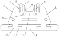
FIG. 1 is a schematic structural diagram of the present invention.
Fig. 2 is a schematic top view of the pallet and side plates of the present invention.
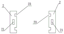
Fig. 3 is a schematic top view of two side panels according to the present invention.
Fig. 4 is a schematic structural diagram of the pallet of the present invention.
FIG. 5 is a schematic top view of the base of the present invention.
Detailed Description
The present invention will be described in further detail with reference to the accompanying drawings.
As shown in fig. 1 to 5, a wind turbine blade operation bracket comprises a base 1, two side plates 2, a supporting plate 3 and two buffering mechanisms 4. The two side plates 2 are arranged on two sides of the base 1. A gap is arranged between the two side plates 2. The middle of the upper ends of the two side plates 2 is provided with a mounting groove 21, and the two sides of the upper ends of the two side plates 2 are provided with sliding grooves 23. The buffer mechanism 4 includes a connecting rod 41 and a buffer coil spring 42. The upper end of one side of the buffer coil spring 42 is fixed with the connecting rod 41. The connecting rod 41 is installed in the installation groove 21 of the side plate 2. As shown in fig. 2 and 4, the supporting plate 3 is provided with sliding teeth 31 on both sides. The supporting plate 3 is connected in the mounting groove 23 between the two side plates 2 in a sliding way through the sliding teeth 31 at the two sides. The bottom of the pallet 3 is mounted on two buffer coil springs 42. More preferably, the base 1 is provided with a moving groove 11. The bottom of the side plate 2 is provided with moving teeth 22. The side plate 2 is movably connected in the moving groove 11 of the base 1 through a moving tooth 22 at the bottom of the side plate. Further preferably, the base 1 and the movable teeth 22 are connected through screws, and screw holes corresponding to the positions are arranged on the base 1 and the movable teeth 22. Further preferably, a bracket 31 with a U-shaped structure is arranged on the supporting plate 3. Further preferably, a wear-resistant layer 32 is arranged in the bracket 31. The wear resistant layer 32 is made of polytetrafluoroethylene.
The wind power blade operation supporting plate 3 supports the supporting plate 3 through the two buffering mechanisms 4, the supporting plate 3 is connected to the two side plates 2 in a sliding mode, the buffering mechanisms 4 formed by the connecting rods 21 and the buffering coil springs 42 are selected, the buffering coil springs 42 are inserted into the two upper ends of the side plates 2 through the connecting rods 21, the sliding positions of the supporting plate 3 are avoided ingeniously, the supporting plate 3 can be buffered effectively when moving up and down through the elastic effect of the buffering coil springs 42, and therefore the wind power blade operation supporting plate 3 can generate beneficial buffering effects when being lifted up and down and can be in smooth transition. The side plate 2 is connected with the base in an inserting mode, so that the disassembly and the replacement are very convenient; be equipped with the support groove 31 of U-shaped structure on layer board 3, be equipped with wearing layer 32 in the support groove 31, wearing layer 32 is made by polytetrafluoroethylene material, so sets up and can make blade and support groove 31 between not take place the friction, protection wind-powered electricity generation blade.
The above description is only for the purpose of illustrating the preferred embodiments of the present invention and is not to be construed as limiting the invention, and any modifications, equivalents, improvements and the like that fall within the spirit and principle of the present invention are intended to be included therein.
Claims (5)
1. A wind power blade operation bracket is characterized by comprising a base, two side plates, a supporting plate and two buffering mechanisms; the two side plates are arranged on two sides of the base; a gap is formed between the two side plates; the middle of the upper ends of the two side plates is provided with an installation groove, and two sides of the upper ends of the two side plates are provided with sliding grooves; the buffer mechanism comprises a connecting rod and a buffer coil spring; the upper end of one side of the buffer coil spring is fixedly connected with a connecting rod; the connecting rod is arranged in the mounting groove of the side plate; sliding teeth are arranged on two sides of the supporting plate; the supporting plate is connected in the mounting groove between the two side plates in a sliding manner through sliding teeth on the two sides; the bottom of the supporting plate is arranged on the two buffer coil springs.
2. The wind blade handling carriage as recited in claim 1, wherein the base has a travel slot; the bottom of the side plate is provided with a moving tooth; the side plates are movably connected in the moving groove of the base through moving teeth at the bottoms of the side plates.
3. The wind blade handling carriage as recited in claim 2, wherein the base and the moving teeth are attached by screws.
4. The wind blade handling bracket as set forth in claim 1, wherein the bracket is provided with a bracket having a U-shaped configuration.
5. The wind blade handling bracket of claim 4, wherein a wear layer is provided in the bracket; the wear-resistant layer is made of polytetrafluoroethylene materials.
Priority Applications (1)
| Application Number | Priority Date | Filing Date | Title |
|---|---|---|---|
| CN201710882367.4A CN107915112B (en) | 2017-09-26 | 2017-09-26 | Wind-powered electricity generation blade operation bracket |
Applications Claiming Priority (1)
| Application Number | Priority Date | Filing Date | Title |
|---|---|---|---|
| CN201710882367.4A CN107915112B (en) | 2017-09-26 | 2017-09-26 | Wind-powered electricity generation blade operation bracket |
Publications (2)
| Publication Number | Publication Date |
|---|---|
| CN107915112A CN107915112A (en) | 2018-04-17 |
| CN107915112B true CN107915112B (en) | 2020-03-24 |
Family
ID=61898689
Family Applications (1)
| Application Number | Title | Priority Date | Filing Date |
|---|---|---|---|
| CN201710882367.4A Active CN107915112B (en) | 2017-09-26 | 2017-09-26 | Wind-powered electricity generation blade operation bracket |
Country Status (1)
| Country | Link |
|---|---|
| CN (1) | CN107915112B (en) |
Family Cites Families (4)
| Publication number | Priority date | Publication date | Assignee | Title |
|---|---|---|---|---|
| WO2008132226A1 (en) * | 2007-04-30 | 2008-11-06 | Vestas Wind Systems A/S | A mounting device |
| CN202545680U (en) * | 2012-04-25 | 2012-11-21 | 淮南市众兴机械制造有限责任公司 | Damping hauling device for monorail hoists |
| CN205293595U (en) * | 2015-11-24 | 2016-06-08 | 上海玻璃钢研究院东台有限公司 | Small wind turbine machine blade combination trammer dress |
| CN205872482U (en) * | 2016-07-11 | 2017-01-11 | 安徽樵森电气科技股份有限公司 | Aircraft transports goods with stabilizing shock absorber support |
-
2017
- 2017-09-26 CN CN201710882367.4A patent/CN107915112B/en active Active
Also Published As
| Publication number | Publication date |
|---|---|
| CN107915112A (en) | 2018-04-17 |
Similar Documents
| Publication | Publication Date | Title |
|---|---|---|
| CN104372870B (en) | A kind of pendulum-type eddy current tuned mass damper damping control device | |
| GB2465524A (en) | Windturbine support tower with pendulum-damping means | |
| CN107791171B (en) | Height-adjustable wind power blade operation bracket | |
| CN107915112B (en) | Wind-powered electricity generation blade operation bracket | |
| CN209233645U (en) | A kind of stable type motor fixing seat | |
| ES2582499T3 (en) | Draft forming device for a loom, in particular for a tape loom | |
| CN208369220U (en) | A kind of mixing reactive power compensator | |
| CN205212354U (en) | It shelves to synthesize collection based on adjustable base | |
| CN109450190A (en) | A kind of lower platen of the automatic stitch welding lifting of motor stator | |
| CN203474095U (en) | Guide assembly of rotor spinner | |
| CN208745501U (en) | A kind of laminating machine film cutting apparatus | |
| CN219536218U (en) | Installation positioning structure of network equipment | |
| CN202717408U (en) | Paper-clamping device for automatic paper-receiving machine | |
| CN202272624U (en) | Adjusting device for sliding block on support leg | |
| CN202687638U (en) | Electric filament-placing machine | |
| CN202379883U (en) | Horizontal-balance double-track translation type transplanter supported horizontally | |
| CN205733882U (en) | A kind of installation site adjustable support mechanism | |
| CN204174373U (en) | A kind of Rapier looms multifunction storage latitude instrument frame | |
| CN218213119U (en) | Supporting platform for transformer detection | |
| CN209843602U (en) | Proximity switch auxiliary triggering tool | |
| CN207700906U (en) | Wind brace suitable for casement window | |
| CN221005968U (en) | Ceramic body bearing kiln furniture | |
| CN204691995U (en) | A kind of wind-driven generator | |
| CN212202929U (en) | Electromechanical device damping device | |
| CN213541092U (en) | Bearing fixing frame with bearing size adaptation adjusting function |
Legal Events
| Date | Code | Title | Description |
|---|---|---|---|
| PB01 | Publication | ||
| PB01 | Publication | ||
| SE01 | Entry into force of request for substantive examination | ||
| SE01 | Entry into force of request for substantive examination | ||
| GR01 | Patent grant | ||
| GR01 | Patent grant |