CN107934026B - Magnetic tile boxing and arranging device - Google Patents

Magnetic tile boxing and arranging device Download PDF

Info

Publication number
CN107934026B
CN107934026B CN201710943875.9A CN201710943875A CN107934026B CN 107934026 B CN107934026 B CN 107934026B CN 201710943875 A CN201710943875 A CN 201710943875A CN 107934026 B CN107934026 B CN 107934026B
Authority
CN
China
Prior art keywords
magnetic
magnetic tile
plate
arrangement
vertical
Prior art date
Legal status (The legal status is an assumption and is not a legal conclusion. Google has not performed a legal analysis and makes no representation as to the accuracy of the status listed.)
Expired - Fee Related
Application number
CN201710943875.9A
Other languages
Chinese (zh)
Other versions
CN107934026A (en
Inventor
杨沛湛
周东
刘黎明
尉越啸
蒋力
徐佰意
褚伟锋
徐暄
Current Assignee (The listed assignees may be inaccurate. Google has not performed a legal analysis and makes no representation or warranty as to the accuracy of the list.)
HANGZHOU WAHAHA PRECISION MACHINERY Co Ltd
Original Assignee
HANGZHOU WAHAHA PRECISION MACHINERY Co Ltd
Priority date (The priority date is an assumption and is not a legal conclusion. Google has not performed a legal analysis and makes no representation as to the accuracy of the date listed.)
Filing date
Publication date
Application filed by HANGZHOU WAHAHA PRECISION MACHINERY Co Ltd filed Critical HANGZHOU WAHAHA PRECISION MACHINERY Co Ltd
Priority to CN201710943875.9A priority Critical patent/CN107934026B/en
Publication of CN107934026A publication Critical patent/CN107934026A/en
Application granted granted Critical
Publication of CN107934026B publication Critical patent/CN107934026B/en
Expired - Fee Related legal-status Critical Current
Anticipated expiration legal-status Critical

Links

Images

Classifications

    • BPERFORMING OPERATIONS; TRANSPORTING
    • B65CONVEYING; PACKING; STORING; HANDLING THIN OR FILAMENTARY MATERIAL
    • B65BMACHINES, APPARATUS OR DEVICES FOR, OR METHODS OF, PACKAGING ARTICLES OR MATERIALS; UNPACKING
    • B65B35/00Supplying, feeding, arranging or orientating articles to be packaged
    • B65B35/30Arranging and feeding articles in groups
    • BPERFORMING OPERATIONS; TRANSPORTING
    • B65CONVEYING; PACKING; STORING; HANDLING THIN OR FILAMENTARY MATERIAL
    • B65BMACHINES, APPARATUS OR DEVICES FOR, OR METHODS OF, PACKAGING ARTICLES OR MATERIALS; UNPACKING
    • B65B23/00Packaging fragile or shock-sensitive articles other than bottles; Unpacking eggs
    • B65B23/20Packaging plate glass, tiles, or shingles
    • BPERFORMING OPERATIONS; TRANSPORTING
    • B65CONVEYING; PACKING; STORING; HANDLING THIN OR FILAMENTARY MATERIAL
    • B65BMACHINES, APPARATUS OR DEVICES FOR, OR METHODS OF, PACKAGING ARTICLES OR MATERIALS; UNPACKING
    • B65B35/00Supplying, feeding, arranging or orientating articles to be packaged
    • B65B35/30Arranging and feeding articles in groups
    • B65B35/40Arranging and feeding articles in groups by reciprocating or oscillatory pushers

Landscapes

  • Engineering & Computer Science (AREA)
  • Mechanical Engineering (AREA)
  • Specific Conveyance Elements (AREA)
  • Sheets, Magazines, And Separation Thereof (AREA)

Abstract

The invention relates to a magnetic tile boxing and arranging device, which overcomes the defects of low boxing efficiency and high labor intensity of workers in the prior art that magnetic tiles are arranged and boxed in a manual mode. The whole process is automated, the labor intensity of workers is reduced, and the boxing efficiency is improved; the magnetic tiles are kept to be horizontally arranged in the automatic arrangement process, the two straight edges of the magnetic tiles are supported in the horizontally arranged state, the convex surfaces of the magnetic tiles are upward, and therefore the magnetic tiles are stable, the gravity center distribution is reasonable, and the magnetic tiles cannot fall off in the arrangement process.

Description

磁瓦装箱排列装置Magnetic tile packing arrangement device

技术领域technical field

本发明属于磁瓦包装领域,尤其是一种磁瓦装箱排列装置。The invention belongs to the field of magnetic tile packaging, in particular to a magnetic tile packing arrangement device.

背景技术Background technique

磁性材料具有磁有序的强磁性物质,广义还包括可应用其磁性和磁效应的弱磁性及反铁磁性物质。目前,磁性材料广泛应用于各行各业。Magnetic materials are ferromagnetic substances with magnetic order, and also include weak magnetic and antiferromagnetic substances to which their magnetic and magnetic effects can be applied in a broad sense. At present, magnetic materials are widely used in all walks of life.

磁性材料的整个生产过程,要经过压制,制坯、烧结等工艺,最后需要经装箱后才能运输,但是目前的磁瓦装箱都是通过人工操作的方式进行,由工人手动将磁瓦一片片装入到纸箱内,装箱效率比较低,工人劳动强度比较大。The entire production process of magnetic materials needs to go through processes such as pressing, blanking, sintering, etc., and finally needs to be packed before transportation. However, the current magnetic tile packing is carried out by manual operation, and workers manually place a piece of magnetic tile. The sheets are put into the carton, the packing efficiency is relatively low, and the labor intensity of the workers is relatively high.

磁瓦装箱是将磁瓦一片片重叠排列呈磁瓦列并装入到纸箱内,磁瓦的重叠排列由工人手动操作,操作效率较低,工人劳动强度比较大。Magnetic tile packing is to overlap and arrange magnetic tiles into magnetic tiles and put them into cartons. The overlapping arrangement of magnetic tiles is manually operated by workers, which has low operation efficiency and relatively high labor intensity of workers.

发明内容SUMMARY OF THE INVENTION

本发明解决了现有技术中磁瓦采用手动的方式进行排列装箱,装箱效率低,工人劳动强度大的缺陷,提供一种磁瓦装箱排列装置,磁瓦上料后能自动重叠排列,并能将重叠排列好的磁瓦列转移到装箱工位进行自动装箱。The invention solves the defects in the prior art that the magnetic tiles are arranged and packed in a manual manner, the packing efficiency is low, and the labor intensity of workers is high, and a magnetic tile packing and arranging device is provided, which can be automatically overlapped and arranged after the magnetic tiles are loaded. , and can transfer the overlapping magnetic tiles to the packing station for automatic packing.

本发明解决其技术问题所采用的技术方案是:一种磁瓦装箱排列装置,包括磁瓦自动排列装置,磁瓦自动排列装置包括用于将始终保持平放状态的磁瓦进行重叠排列的排列上料机构,磁瓦排列采用逐一向前推、并竖向重叠的方式进行排列形成磁瓦列,同一磁瓦列相邻磁瓦的凸面与凹面相贴合。磁瓦自动排列装置主要将平放的磁瓦进行重叠,重叠后形成磁瓦列,每排完一列就装箱一次,直到纸箱装满为止,可以是单排磁瓦流直接进行重叠排列,每次自动排成一列,也可以是单排磁瓦流上料后转化成多排,根据纸箱尺寸每次自动排成多列,多列磁瓦列一次装入到纸箱内;磁瓦自动排列过程中保持磁瓦平放,平放的状态是磁瓦的两直边支撑,凸面朝上,这样磁瓦比较稳定,重心分配合理,排列过程中不会发生掉落等现象;整个过程实现自动化,减轻工人劳动强度并提高装箱效率。The technical solution adopted by the present invention to solve the technical problem is as follows: a magnetic tile packing and arranging device, comprising an automatic magnetic tile arranging device, and the magnetic tile automatic arranging device includes a magnetic tile for overlapping and arranging the magnetic tiles that are always kept in a flat state. Arranging the feeding mechanism, the magnetic tiles are arranged by pushing forward one by one and vertically overlapping to form a magnetic tile row, and the convex and concave surfaces of adjacent magnetic tiles in the same magnetic tile row are attached. The magnetic tile automatic arranging device mainly overlaps the flat magnetic tiles, and forms a magnetic tile row after overlapping. After each row is completed, it is packed once until the carton is full. It can be automatically arranged into one row at a time, or it can be converted into multiple rows after feeding a single row of magnetic tiles, and automatically arranged into multiple rows each time according to the size of the carton, and the multi-row magnetic tile rows are loaded into the carton at one time; the magnetic tile is automatically arranged in the process. The magnetic tile is kept flat in the middle, and the flat state is supported by the two straight sides of the magnetic tile, with the convex surface facing upward, so that the magnetic tile is relatively stable, the distribution of the center of gravity is reasonable, and the phenomenon of falling during the arrangement process will not occur; the whole process is automated. , reduce the labor intensity of workers and improve packing efficiency.

作为优选,排列上料机构具有可调挡板机构,使向前输送的磁瓦流按需要排列整齐;在排列上料机构的末端位置还具有将向前输送的磁瓦流截断,并每次只推进一块或一排磁瓦进行重叠排列的重叠排列执行机构。排列上料机构将磁瓦逐一重叠排列,重叠排列的意思是磁瓦保持平放,下一块磁瓦放置到上一块磁瓦的上方重叠;磁瓦上料过程属于依次相连的磁瓦流状态,而重叠属于单块或单排操作,为避免后面的磁瓦对正在重叠排列的磁瓦造成阻碍,向前输送的磁瓦流要截断,只推进最前面的一块或一排磁瓦进行重叠排列。Preferably, the arrangement and feeding mechanism has an adjustable baffle mechanism, so that the magnetic tile flow conveyed forward is arranged neatly as required; at the end position of the arrangement and feeding mechanism, there is also a function to cut off the magnetic tile flow conveyed forward, and each time Overlapping actuators that push only one or one row of magnetic tiles for overlapping arrangement. The arrangement and feeding mechanism arranges the magnetic tiles one by one in an overlapping arrangement. The overlapping arrangement means that the magnetic tiles are kept flat, and the next magnetic tile is placed on the top of the previous magnetic tile. The overlap is a single-block or single-row operation. In order to prevent the following magnetic tiles from hindering the overlapping magnetic tiles, the forward-transported magnetic tile flow should be cut off, and only the front one or a row of magnetic tiles should be pushed for overlapping arrangement. .

作为优选,重叠排列执行机构采用自由下落的截断方式,重叠排列执行机构具有阶梯式的支撑结构,支撑结构处设置有推出机构。自由下落后通过支撑结构支撑,支撑结构为阶梯式,与被阻挡的磁瓦流相分离,通过推出机构推出进行重叠。Preferably, the overlapping arrangement actuator adopts a free-fall truncation method, the overlapping arrangement actuator has a stepped support structure, and a push-out mechanism is provided at the support structure. After free fall, it is supported by a support structure, which is stepped, separated from the blocked magnetic tile flow, and pushed out by a push-out mechanism to overlap.

作为优选,磁瓦自动排列装置还包括将重叠排列好的磁瓦列转移到装箱工位的排列转移机构,排列转移机构具有随动支撑机构,随动支撑机构具有能根据所支撑的重叠磁瓦列的重叠高度,随动调整其支撑高度的调整机构,以便磁瓦顺利进行重叠排列,并到达推移位置。由于磁瓦重叠排列后高度增加,磁瓦上料的高度不变,因此需要对高度进行调整以相互匹配,这就要求改变上料的高度或者降低重叠磁瓦列,通过随动支撑机构可以自动调节磁瓦列的高低位置,保持每一次磁瓦重叠的位置不变。Preferably, the magnetic tile automatic arranging device further includes an arrangement transfer mechanism for transferring the overlapped and arranged magnetic tile arrays to the packing station, the arrangement transfer mechanism has a follow-up support mechanism, and the follow-up support mechanism The overlapping height of the tile column, the adjustment mechanism that adjusts its support height along with it, so that the magnetic tile can be smoothly overlapped and arranged to reach the push position. Since the height of the magnetic tiles increases after they are overlapped and arranged, the height of the magnetic tiles does not change, so the heights need to be adjusted to match each other, which requires changing the height of the material or reducing the overlapping magnetic tiles, which can be automatically Adjust the high and low position of the magnetic tile column to keep the overlapping position of each magnetic tile unchanged.

作为优选,排列转移机构还包括将重叠排列的磁瓦列从随动支撑机构上转移的横向推移机构。Preferably, the arrangement transfer mechanism further includes a lateral shift mechanism for transferring the overlapping magnetic tile arrays from the follow-up support mechanism.

作为优选,排列转移机构的侧边还设置有承接转移过来的磁瓦列并将该磁瓦列推入到纸箱内的磁瓦抓手机构。Preferably, the side of the arrangement transfer mechanism is also provided with a magnetic tile gripper mechanism for receiving the transferred magnetic tile row and pushing the magnetic tile row into the carton.

作为优选,磁瓦抓手机构采用两侧开口的框形结构,磁瓦抓手机构内部设置有推出机构,一侧开口用于承接转移来的重叠的磁瓦列,另一侧开口用于将重叠的磁瓦列推出并推入到纸箱内。Preferably, the magnetic tile gripper mechanism adopts a frame-shaped structure with openings on both sides, and a push-out mechanism is arranged inside the magnetic tile gripper mechanism. The overlapping magnetic tiles are pushed out and pushed into the carton.

作为优选,磁瓦抓手机构与排列转移机构之间设置有门架式升降拦挡机构,门架式升降拦挡机构上具有磁瓦列转接导向机构。Preferably, a gantry-type lifting and blocking mechanism is provided between the magnetic tile gripper mechanism and the arrangement transfer mechanism, and the gantry-type lifting and blocking mechanism is provided with a magnetic tile row transfer guide mechanism.

作为优选,磁瓦自动排列装置还配有纸条自动放置机构用于将纸条自动放入到相邻重叠的磁瓦列之间的间隙处以分隔两相邻的重叠磁瓦列。Preferably, the device for automatically arranging magnetic tiles is further equipped with an automatic paper strip placing mechanism for automatically placing paper strips in the gaps between adjacent overlapping magnetic tile columns to separate two adjacent overlapping magnetic tile columns.

作为优选,排列上料机构的末端设置有重叠排列的磁瓦列随动支撑机构,随动支撑机构上设置有磁瓦列导向夹板机构,并设置有将磁瓦列直接推入到纸箱内的装箱执行机构。导向夹板机构将重叠排列的磁瓦列进行横向夹紧,夹紧后能缩小磁瓦列占据的空间,再通过磁瓦列推出机构直接将重叠好的磁瓦列推入到纸箱内完成装箱。Preferably, the end of the arranging and feeding mechanism is provided with an overlapping magnetic tile row follow-up support mechanism, the follower support mechanism is provided with a magnetic tile row guide splint mechanism, and is provided with a magnetic tile row to directly push into the carton. Pack the actuator. The guide splint mechanism clamps the overlapping magnetic tiles horizontally, which can reduce the space occupied by the magnetic tiles after clamping, and then directly push the overlapped magnetic tiles into the carton through the magnetic tile pushing mechanism to complete the packing. .

本发明的有益效果是:磁瓦自动排列装置主要将单一平放的磁瓦进行重叠,重叠后形成磁瓦列,每排完一列就装箱一次,直到纸箱装满为止,可以是单排磁瓦流直接进行重叠排列,每次自动排成一列,也可以是单排磁瓦流上料后转化成多排,根据纸箱尺寸每次自动排成多列,多列磁瓦列一次装入到纸箱内;磁瓦自动排列过程中保持磁瓦平放,平放的状态是磁瓦的两直边支撑,凸面朝上,这样磁瓦比较稳定,重心分配合理,排列过程中不会发生掉落等现象;整个过程实现自动化,减轻工人劳动强度并提高装箱效率。The beneficial effect of the invention is that the magnetic tile automatic arrangement device mainly overlaps a single flat magnetic tile to form a magnetic tile row after overlapping, and each row is packed once until the carton is full, which can be a single row of magnetic tiles. The tile streams are directly overlapped, and automatically arranged in one row each time, or a single row of magnetic tile streams can be converted into multiple rows after feeding. In the carton; during the automatic arrangement of the magnetic tiles, keep the magnetic tiles flat, and the flat state is supported by the two straight sides of the magnetic tiles, with the convex side facing up, so that the magnetic tiles are relatively stable, the center of gravity distribution is reasonable, and the arrangement process will not happen. The whole process is automated, reducing the labor intensity of workers and improving the efficiency of packing.

附图说明Description of drawings

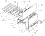
图1是本发明一种左侧结构示意图;Fig. 1 is a kind of left side structure schematic diagram of the present invention;

图2是本发明一种右侧结构示意图;Fig. 2 is a kind of right side structural representation of the present invention;

图3是本发明一种排列架结构示意图;Fig. 3 is a kind of arrangement frame structure schematic diagram of the present invention;

图4是本发明一种门架式升降拦挡机构的结构示意图;4 is a schematic structural diagram of a gantry-type lifting and blocking mechanism of the present invention;

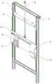
图5是本发明一种门架结构示意图;Fig. 5 is a kind of gantry structure schematic diagram of the present invention;

图6是本发明一种磁瓦抓手机构的结构示意图;6 is a schematic structural diagram of a magnetic tile gripper mechanism of the present invention;

图7是本发明第二种结构示意图;Fig. 7 is the second structure schematic diagram of the present invention;

图中:1、排列上料输送带,2、排列上料支架,3、可调挡板,4、第一节,5、第二节,6、第三节,7、过渡平台,8、导轨板,9、导轨,10、第一伸缩缸,11、第二伸缩缸,12、推出板,13、转移推板,14、竖向挡板,15、转移架体,16、后窗口,17、第三伸缩缸,18、第四伸缩缸,19、立板,20、上架板,21、滑块,22、纸条料斗,23、第五伸缩缸,24、排列通道,25、磁瓦支撑横板,26、转移推板移动槽,27、竖板,28、搁板,29、纸条定位板,30、纸条,31、翻边,32、前挡板,33、吸纸机构,34、吸盘,35、第六伸缩缸,36、档条,37、辅助推板,38、底座,39、竖向限位板,40、调节间隙,41、落纸槽,42、挡部,43、辅助平衡板,44、第七伸缩缸,45、抓手座,46、上压板,47、引导板,48、栅格板,49、横移导向板,50、安装板,51、升降伸缩缸,52、磁瓦装箱推板,53、型材,54、导向槽,55、槽口,56、第八伸缩缸,57、门架,58、支座板,59、夹紧伸缩缸,60、导向夹板,61、转辊,62、第九伸缩缸,63、限位板。In the picture: 1. Arrange the feeding conveyor belt, 2. Arrange the feeding bracket, 3. Adjustable baffle plate, 4. Section 1, 5. Section 2, 6. Section 3, 7. Transition platform, 8. Guide rail plate, 9, guide rail, 10, first telescopic cylinder, 11, second telescopic cylinder, 12, push plate, 13, transfer push plate, 14, vertical baffle, 15, transfer frame body, 16, rear window, 17, the third telescopic cylinder, 18, the fourth telescopic cylinder, 19, the vertical plate, 20, the upper shelf, 21, the slider, 22, the paper strip hopper, 23, the fifth telescopic cylinder, 24, the arrangement channel, 25, the magnet Tile support horizontal plate, 26, transfer push plate moving slot, 27, vertical plate, 28, shelf, 29, paper strip positioning plate, 30, paper strip, 31, flange, 32, front baffle, 33, suction paper Mechanism, 34, suction cup, 35, sixth telescopic cylinder, 36, stop bar, 37, auxiliary push plate, 38, base, 39, vertical limit plate, 40, adjustment gap, 41, paper drop slot, 42, stopper Section, 43, Auxiliary Balance Plate, 44, Seventh Telescopic Cylinder, 45, Gripper Seat, 46, Upper Pressing Plate, 47, Guide Plate, 48, Grid Plate, 49, Traverse Guide Plate, 50, Mounting Plate, 51 , Lifting telescopic cylinder, 52, Magnetic tile packing push plate, 53, Profile, 54, Guide groove, 55, Notch, 56, Eighth telescopic cylinder, 57, Gantry, 58, Support plate, 59, Clamping Telescopic cylinder, 60, guide splint, 61, rotating roller, 62, ninth telescopic cylinder, 63, limit plate.

具体实施方式Detailed ways

下面通过具体实施例,并结合附图,对本发明的技术方案作进一步具体的说明。The technical solutions of the present invention will be further specifically described below through specific embodiments and in conjunction with the accompanying drawings.

实施例1:一种磁瓦装箱排列装置(图1图2),包括排列上料机构和排列转移机构。Embodiment 1: A magnetic tile packing and arranging device (Fig. 1 and Fig. 2), including an arrangement feeding mechanism and an arrangement transfer mechanism.

排列上料机构(参见图1图2)包括排列上料支架2、环形套置于排列上料支架上的排列上料输送带1、设置于排列上料输送带上方的可调挡板3、设置于排列上料支架末端的过渡板7、设置于过渡板后侧边上方的排列等待机构。可调挡板之间形成磁瓦前进的排列通道24,可调挡板分为铰接的三段,分别为第一节4、第二节5和第三节6,第一节与第二节相铰接,第二节与第三节相铰接,铰接采用阻尼铰接,即调节好相互之间的间隔距离后即可稳定,不会随意转动。第三节的一部分固定于过渡板上,其余部分和第二节及第一节均悬空于排列上料输送带上方。排列上料支架上方固定有第五伸缩缸23,第五伸缩缸伸缩杆的端部固定有辅助推板37,辅助推板竖向悬垂,辅助推板的下侧边对应第三节的位置设置有避让槽口,第三节正好卡入到避让槽口内,辅助推板的下侧边距离排列上料输送带上表面的距离小于磁瓦的弧形高度,当一个工期结束,最后几块磁瓦从排列上料输送带转移到过渡板上后没有动力继续向前,此时第五伸缩缸动作,通过辅助推板推动最后磁瓦的侧边位置,将磁瓦推入到排列位置。过渡板朝向排列上料输送带的侧边为凹弧形,过渡板的另一侧边为竖直边。过渡板下方对应竖直边的位置设置有搁板28,搁板伸出到过渡板竖直边以外,搁板上表面与过渡板上表面之间的高度差大于等于磁瓦的弧形高度,搁板上表面与过渡板下表面之间留有间隙。过渡板的下方还设置有第一伸缩缸10,第一伸缩缸的伸缩方向与排列上料输送带前进方向一致,第一伸缩缸伸缩杆端部连接有推出板12,推出板处于过渡板与搁板之间的间隙位置。过渡板的上方位置还固定有第六伸缩缸35,第六伸缩缸的伸缩方向为竖直方向,第六伸缩缸伸缩杆的端部固定有档条36,档条呈L形,档条的竖边朝下,竖边与过渡边的的竖直边之间的距离小于磁瓦的宽度,即磁瓦被档条的竖边阻挡后不会从过渡板上掉落到搁板上,以此来控制每一次只有一排磁瓦从过渡板上掉落到搁板上,以便推出板将该一排磁瓦从搁板上推出进行层叠排列。The arrangement feeding mechanism (see Fig. 1 and Fig. 2) includes an arrangement feeding bracket 2, an arrangement feeding conveyor belt 1 which is annularly sleeved on the arrangement feeding bracket, and an adjustable baffle plate 3 arranged above the arrangement feeding conveyor belt. The transition plate 7 arranged at the end of the arrangement feeding bracket, and the arrangement waiting mechanism arranged above the rear side of the transition plate. An arrangement channel 24 for the magnetic tiles to advance is formed between the adjustable baffles, and the adjustable baffles are divided into three hinged sections, namely the first section 4, the second section 5 and the third section 6, the first section and the second section. The second section is hinged with the third section, and the hinge adopts damping hinge, that is, after adjusting the distance between each other, it can be stabilized and will not rotate at will. A part of the third section is fixed on the transition plate, and the rest, the second section and the first section are suspended above the arrangement feeding conveyor belt. A fifth telescopic cylinder 23 is fixed above the arrangement and feeding support, and an auxiliary push plate 37 is fixed at the end of the telescopic rod of the fifth telescopic cylinder. The auxiliary push plate hangs vertically, and the lower side of the auxiliary push plate corresponds to the position of the third section. There is an avoidance notch, the third section just snaps into the avoidance notch, the distance between the lower side of the auxiliary push plate and the upper surface of the feeding conveyor belt is less than the arc height of the magnetic tile, when a construction period ends, the last few pieces of magnetic After the tile is transferred from the arrangement feeding conveyor belt to the transition plate, there is no power to continue to move forward. At this time, the fifth telescopic cylinder acts to push the side position of the last magnetic tile through the auxiliary push plate, and push the magnetic tile into the arrangement position. The side of the transition plate facing the arrangement feeding conveyor belt is concave arc, and the other side of the transition plate is a vertical side. A shelf 28 is arranged below the transition plate at the position corresponding to the vertical edge, the shelf extends beyond the vertical edge of the transition plate, and the height difference between the upper surface of the shelf and the upper surface of the transition plate is greater than or equal to the arc height of the magnetic tile, There is a gap between the upper surface of the shelf and the lower surface of the transition plate. A first telescopic cylinder 10 is also arranged below the transition plate. The telescopic direction of the first telescopic cylinder is consistent with the advancing direction of the arrangement feeding conveyor belt. The end of the telescopic rod of the first telescopic cylinder is connected with a push-out plate 12. The push-out plate is located between the transition plate and the conveyor belt. The position of the gap between the shelves. A sixth telescopic cylinder 35 is also fixed at the upper position of the transition plate. The telescopic direction of the sixth telescopic cylinder is the vertical direction, and the end of the telescopic rod of the sixth telescopic cylinder is fixed with a rail 36. The rail is L-shaped, and the The vertical side faces down, and the distance between the vertical side and the vertical side of the transition side is less than the width of the magnetic tile, that is, the magnetic tile will not fall from the transition plate to the shelf after being blocked by the vertical side of the rail, so as to avoid This controls that only one row of magnetic tiles is dropped from the transition plate to the shelf at each time, so that the push-out plate pushes out the row of magnetic tiles from the shelf for stacked arrangement.

排列转移机构(参见图1图2图3)处于排列上料机构的的输出端一侧,排列转移机构包括用于放置层叠排列的磁瓦的转移架体15及横向转移层叠排列的磁瓦的第二伸缩缸11。第二伸缩缸通过滑块及导轨9固定于导轨板8上,导轨板处于过渡板的下方,导轨为两根相互平行,两导轨横向固定于导轨板的上下侧边位置。第二伸缩缸侧边连接有驱动第二伸缩缸整体横向移动的驱动杆(图中未视出),在驱动杆的驱动下,第二伸缩缸沿着导轨横向移动。第二伸缩缸伸缩杆的端部固定有工字形的转移推板13,转移推板的作用部为平板状,转移推板竖向布置。转移架体包括底座38,竖直固定于底座上的竖向挡板14和竖板27,竖向挡板与竖板相互平行,竖向挡板朝向排列上料机构的一侧,竖板处于另一侧,竖向挡板上设置有转移推板移动槽26,转移推板移动槽呈横倒的T形,端部为竖向状,竖向状供转移推板插入到竖向挡板与竖板之间,横线部位一直贯通到竖向挡板的侧边部位,横向部位与转移推板工字的中间细部配合,便于转移推板横线移动。竖板朝向竖向挡板的表面两侧竖向固定有导轨,导轨上通过滑块连接有磁瓦支撑横板25,磁瓦重叠后坐落于磁瓦支撑横板上,磁瓦支撑横板的滑块连接在驱动机构上(图中未视出),随着磁瓦重叠的层数增加,则同时磁瓦支撑横板会相应依次下降,使得从搁板上被推出板推出的磁瓦能直接重叠,磁瓦被转移后,磁瓦支撑横板又能上升到原始位置,方便推出板推出磁瓦并坐落到磁瓦支撑横板上作为重叠第一层。竖板朝向竖向挡板的一侧还固定有水平的两个导轨,导轨上设置有多块滑块,上下对应的两滑块之间连接有竖向限位板39,竖向限位板之间相互分离形成调节间隙40,竖板的侧边固定有一块固定板,固定板与相邻的竖向限位板分离并形成调节间隙,每一个调节间隙均对应一个磁瓦重叠排列的位置,竖向限位板的上部固定有纸条导向槽,纸条导向槽由三块立板19拼合而成,纸条导向槽的上部入口端为扩口状。竖向限位板的下部设置有竖槽,竖槽的位置与纸条导向槽的位置相对应。竖向限位板的背面固定有第三伸缩缸17,竖向板上设置有后窗口16,第三伸缩缸从后窗口处伸出,本实施例中,竖向限位板共5块,加上固定板共形成5个磁瓦重叠排列位置,第三伸缩缸共5个,5个第三伸缩缸呈水平排列。第三伸缩缸伸缩杆的端部固定有纸条定位板29,纸条定位板的位置与竖槽的位置相对应,纸条定位板的上端与纸条导向槽的下端相对齐,纸条定位板具有纸条定位槽,纸条定位槽与对应的纸条导向槽处于同一竖向平面,纸条定位板随第三伸缩缸伸缩而从竖槽内伸出或缩回,纸条定位板伸出的位置正好处于两列重叠排列的磁瓦之间,磁瓦重叠到磁瓦支撑横板上并抵靠于两相邻的竖向限位板表面或者固定板与相邻的竖向限位板表面,纸条定位板从竖槽内缩回,则重叠的磁瓦可在转移推板的推动下横向转移。通过滑块在导轨上的移动,可以改变调节间隙的大小,从而改变磁瓦重叠排列的位置的宽度,这样可以适应不同弧长的磁瓦。竖板对应固定板的侧边固定有第四伸缩缸18,第四伸缩缸的伸缩杆朝向竖向挡板,伸缩杆的端部固定有竖向平板状的辅助平衡板43。转移架体的上方设置有上架板20,上架板上下两侧边上固定有水平的导轨,导轨通过滑块21连接有纸条料斗22,纸条料斗呈槽形,槽形内部放置有并排的纸条30,槽形的开口处于侧面,槽形的两侧边设置有相对翻折的翻边31。纸条料斗呈倾斜状,纸条入口在上,纸条出口在下,纸条料斗在纸条出口的位置翻折有前挡板32,前挡板的下侧边一直延伸到纸条料斗以下部位,纸条料斗的下边设置有一块短板,短板与前挡板之间形成落纸槽41。前挡板的前侧表面上固定有吸纸机构33,前挡板上设置有穿孔,吸纸机构包括吸盘34,吸盘穿过穿孔伸入到纸条料斗内。纸条料斗在靠近纸条出口的位置设置有挡部42,挡部阻挡纸条。只有吸盘吸住最前面的纸条,在吸纸机构的作用拉出并越过挡部,此时纸条对应落纸槽,松开吸纸机构,纸条从落纸槽内落下。落纸槽与纸条导向槽相对应,本实施例中有4个纸条导向槽,1个纸条料斗,因此纸条料斗连接有移动机构(图中未视出),在移动机构的驱动下,纸条料斗在导轨上移动,每一次移动,落纸槽都与对应的纸条导向槽相对。The arrangement transfer mechanism (see Fig. 1, Fig. 2, and Fig. 3) is located on the output end side of the arrangement feeding mechanism. The arrangement and transfer mechanism includes a transfer frame body 15 for placing the stacked magnetic tiles and a lateral transfer of the stacked magnetic tiles. The second telescopic cylinder 11 . The second telescopic cylinder is fixed on the guide rail plate 8 through the slider and the guide rail 9, the guide rail plate is below the transition plate, the guide rails are two parallel to each other, and the two guide rails are laterally fixed on the upper and lower sides of the guide rail plate. The side of the second telescopic cylinder is connected with a driving rod (not shown in the figure) that drives the entire second telescopic cylinder to move laterally. Under the driving of the driving rod, the second telescopic cylinder moves laterally along the guide rail. An I-shaped transfer push plate 13 is fixed at the end of the telescopic rod of the second telescopic cylinder, the action portion of the transfer push plate is a flat plate, and the transfer push plate is arranged vertically. The transfer frame body includes a base 38, a vertical baffle 14 and a vertical plate 27 vertically fixed on the base, the vertical baffle and the vertical plate are parallel to each other, the vertical baffle faces the side of the arrangement feeding mechanism, and the vertical plate is in On the other side, the vertical baffle is provided with a transfer push plate moving groove 26, the transfer push plate moving groove is in a horizontally inverted T shape, and the end is vertical, and the vertical shape is for the transfer push plate to be inserted into the vertical baffle. Between the vertical plate and the vertical plate, the horizontal line part runs through to the side part of the vertical baffle plate, and the horizontal part cooperates with the middle detail of the I-shape of the transfer push plate, which is convenient for the horizontal line of the transfer push plate to move. Guide rails are vertically fixed on both sides of the surface of the vertical plate facing the vertical baffle plate. The guide rail is connected with a magnetic tile supporting horizontal plate 25 through a slider. The magnetic tile is placed on the magnetic tile supporting horizontal plate after overlapping. The slider is connected to the drive mechanism (not shown in the figure), and as the number of overlapping layers of the magnetic tiles increases, the magnetic tile supporting horizontal plates will descend accordingly, so that the magnetic tiles pushed out from the shelf can Directly overlapping, after the magnetic tile is transferred, the magnetic tile supporting horizontal plate can be raised to the original position again, so that the push-out plate can push out the magnetic tile and sit on the magnetic tile supporting horizontal plate as the first layer of overlapping. The side of the vertical plate facing the vertical baffle is also fixed with two horizontal guide rails, a plurality of sliders are arranged on the guide rails, and a vertical limit plate 39 is connected between the upper and lower corresponding sliders. They are separated from each other to form an adjustment gap 40. A fixed plate is fixed on the side of the vertical plate. The fixed plate is separated from the adjacent vertical limit plate to form an adjustment gap. Each adjustment gap corresponds to a position where a magnetic tile is overlapped and arranged. , The upper part of the vertical limit plate is fixed with a paper strip guide groove, the paper strip guide groove is assembled by three vertical plates 19, and the upper entrance end of the paper strip guide groove is flared. The lower part of the vertical limit plate is provided with a vertical groove, and the position of the vertical groove corresponds to the position of the paper strip guide groove. A third telescopic cylinder 17 is fixed on the back of the vertical limit plate, a rear window 16 is arranged on the vertical plate, and the third telescopic cylinder protrudes from the rear window. In this embodiment, there are five vertical limit plates in total, In addition to the fixing plate, there are 5 overlapping arrangement positions of the magnetic tiles, and there are 5 third telescopic cylinders in total, and the 5 third telescopic cylinders are arranged horizontally. A paper strip positioning plate 29 is fixed at the end of the telescopic rod of the third telescopic cylinder. The position of the paper strip positioning plate corresponds to the position of the vertical slot. The upper end of the paper strip positioning plate is aligned with the lower end of the paper strip guide groove. The board has a paper strip positioning groove. The paper strip positioning groove and the corresponding paper strip guiding groove are in the same vertical plane. The exit position is exactly between two rows of overlapping magnetic tiles, the magnetic tiles are overlapped on the magnetic tile support transverse plate and abut against the surfaces of two adjacent vertical limit plates or the fixed plate and the adjacent vertical limit plates. On the surface of the board, the paper strip positioning board is retracted from the vertical slot, and the overlapping magnetic tiles can be transferred laterally under the push of the transfer push plate. Through the movement of the slider on the guide rail, the size of the adjustment gap can be changed, thereby changing the width of the overlapping arrangement of the magnetic tiles, which can adapt to the magnetic tiles of different arc lengths. A fourth telescopic cylinder 18 is fixed on the side of the vertical plate corresponding to the fixed plate, the telescopic rod of the fourth telescopic cylinder faces the vertical baffle, and the end of the telescopic rod is fixed with a vertical flat plate-shaped auxiliary balance plate 43 . An upper frame plate 20 is arranged above the transfer frame body, horizontal guide rails are fixed on the upper and lower sides of the upper frame plate, and the guide rail is connected with a paper strip hopper 22 through a slider 21. In the paper strip 30, the opening of the groove is on the side, and the two sides of the groove are provided with flanges 31 that are folded relative to each other. The paper strip hopper is inclined, the paper strip inlet is on the top, and the paper strip outlet is below. The paper strip hopper is folded with a front baffle 32 at the position of the paper strip outlet, and the lower side of the front baffle extends to the part below the paper strip hopper. , a short board is arranged on the lower side of the paper strip hopper, and a paper drop slot 41 is formed between the short board and the front baffle. A paper suction mechanism 33 is fixed on the front side surface of the front baffle, and perforations are arranged on the front baffle. The paper strip hopper is provided with a blocking part 42 at a position close to the paper strip outlet, and the blocking part blocks the paper strips. Only the suction cup sucks the frontmost paper strip, pulls it out and crosses the blocking part under the action of the paper suction mechanism, at this time the paper strip corresponds to the paper drop slot, release the suction mechanism, and the paper strip falls from the paper drop slot. The paper drop slot corresponds to the paper strip guide slot. In this embodiment, there are 4 paper strip guide slots and one paper strip hopper. Therefore, the paper strip hopper is connected with a moving mechanism (not shown in the figure), which is driven by the moving mechanism. down, the paper strip hopper moves on the guide rail, and each time it moves, the paper unloading slot is opposite to the corresponding paper strip guide slot.

排列转移机构的侧边部位设置有门架式升降拦挡机构,门架式升降拦挡机构上具有磁瓦列转接导向机构。门架式升降拦挡机构包括一个门架57(参见图4图5),门架是由型材53首尾相接而成框形结构,两竖向的型材之间固定有安装板50,安装板的中间位置固定有升降伸缩缸51,竖向型材的侧面上固定有竖向的导轨,导轨通过滑块连接有横移导向板49,横移导向板竖向放置,横移导向板的背面通过连接柱与升降伸缩缸的伸缩缸端部相铰接,由升降伸缩缸驱动横移导向板升降。横移导向板靠近排列转移机构的一端上固定有引导板47,引导板呈弯折状,弯折后与横移导向板之间形成一个供重叠磁瓦通过的方形的通道,引导板分为两块,上下布置,两块引导板相对的部位分开形成槽口55,槽口的位置正好与转移推板移动槽处于同一水平线上。引导板的侧边与磁瓦支撑横板的侧边相对接,当需要转移重叠排列的磁瓦时,通道的底面与磁瓦支撑横板的上表面相平齐。横移导向板中间偏上部位设置有横向的导向槽54,横移导向板的背面固定有两条水平的相互平行的导轨,导轨上设置有滑块,上下滑块之间由联板相连成一体可以同步滑动,横移导向板的正面位置设置有栅格板48,栅格板具有倾斜的栅槽,栅格板侧边的上下两段上具有折边,其中处于上方的折边穿过导向槽与背面的联板上端相固定,下方的折边从横移导向板的下侧边穿过与背面的联板下端相固定。联板的侧边与竖向型材的侧边之间连接有横移伸缩缸。The side part of the arrangement transfer mechanism is provided with a gantry-type lifting and blocking mechanism, and the gantry-type lifting and blocking mechanism is provided with a magnetic tile row transfer guide mechanism. The gantry-type lifting and blocking mechanism includes a gantry 57 (see Fig. 4 and Fig. 5 ). The gantry is a frame-shaped structure formed by connecting profiles 53 end to end. A mounting plate 50 is fixed between the two vertical profiles. The lifting telescopic cylinder 51 is fixed in the middle position, and the vertical guide rail is fixed on the side of the vertical profile. The guide rail is connected with a traverse guide plate 49 through the slider. The column is hinged with the end of the telescopic cylinder of the lift telescopic cylinder, and the traverse guide plate is driven to lift up and down by the lift telescopic cylinder. A guide plate 47 is fixed on one end of the traverse guide plate close to the arrangement transfer mechanism. The guide plate is bent, and a square channel is formed between the traverse guide plate and the traverse guide plate for the overlapping magnetic tiles to pass through. The guide plate is divided into two parts. Two pieces are arranged up and down, and the opposite parts of the two guide plates are separated to form a notch 55, and the position of the notch is exactly on the same horizontal line as the moving groove of the transfer push plate. The side of the guide plate is abutted with the side of the magnetic tile supporting transverse plate, and when the overlapping magnetic tiles need to be transferred, the bottom surface of the channel is flush with the upper surface of the magnetic tile supporting transverse plate. A transverse guide groove 54 is arranged in the upper part of the middle of the traverse guide plate, and two horizontal parallel guide rails are fixed on the back of the traverse guide plate. The one body can slide synchronously. The front position of the traverse guide plate is provided with a grid plate 48. The grid plate has inclined grid grooves. The guide groove is fixed with the upper end of the connecting plate on the back, and the lower folded edge passes through the lower side of the traverse guide plate and is fixed with the lower end of the connecting plate on the back. A lateral movement telescopic cylinder is connected between the side edge of the connecting plate and the side edge of the vertical profile.

门架的下部位置设置有用于承接从排列转移机构处横移过来的磁瓦列的磁瓦抓手机构,磁瓦抓手机构包括抓手座78,抓手座(参见图4图6)包括后板、左侧板和底板,后板、底板和左侧板围成的空间与磁瓦装箱用的纸箱的尺寸相适配,本实施例中,纸箱能放置5排重叠的磁瓦。抓手座内部设置有可在抓手座内移动的磁瓦装箱推板52,磁瓦装箱推板背面固定有第七伸缩缸44,第七伸缩缸从后板的中间穿出,重叠排列的磁瓦列进入到抓手座内,磁瓦装箱推板向前将磁瓦列退出抓手座并推入到纸箱内。抓手座内还设置有竖向布置并可竖向伸缩的第八伸缩缸56,第八伸缩缸的伸缩杆的端部固定有上压板46,上压板可随伸缩杆伸缩而上下移动,上压板的外侧边设置有槽缝形成相互间隙分隔开的压片结构,两压片为一组,一列重叠的磁瓦对应一组压片,压片组与组之间的槽缝宽度小,同一组的两压片之间的槽缝宽度大,同一组的两压片相对的侧面为凹的弧面,该弧面与磁瓦的凸面相贴合。重叠排列的磁瓦进入到抓手座内,上压板下行,压片轻轻压住最上层的磁瓦,同一组两压片之间的槽缝正好对应磁瓦凸起的最高位置。抓手座的左侧板的前侧边缘呈倾斜的栅格状,栅格的间隙和倾斜角度与栅格板的间隙和倾斜角度相同,使得栅格板可以从左侧板的栅格内通过。抓手座的右侧边与引导板的左侧处于同一竖向平面,由于抓手座没有右侧板,重叠排列的磁瓦从引导板的通道内移出后可以直接转移到抓手座内,衔接顺畅。The lower part of the gantry is provided with a magnetic tile gripper mechanism for receiving the magnetic tile arrays traversed from the arrangement transfer mechanism. The magnetic tile gripper mechanism includes a gripper seat 78, and the gripper seat (see FIG. 4 and FIG. 6 ) includes The space enclosed by the rear panel, the left panel and the bottom panel, and the space enclosed by the back panel, the bottom panel and the left panel are adapted to the size of the carton used for packing the magnetic tiles. In this embodiment, the carton can accommodate 5 rows of overlapping magnetic tiles. The inside of the gripper seat is provided with a magnetic tile packing push plate 52 that can move in the gripper seat, and a seventh telescopic cylinder 44 is fixed on the back of the magnetic tile packing push plate. The arranged magnetic tiles enter the gripper seat, and the magnetic tile packing push plate forwards the magnetic tiles out of the gripper seat and pushes them into the carton. The grip seat is also provided with an eighth telescopic cylinder 56 that is vertically arranged and can be stretched vertically. An upper pressure plate 46 is fixed at the end of the telescopic rod of the eighth telescopic cylinder, and the upper pressure plate can move up and down with the telescopic rod. The outer side of the pressing plate is provided with a slot to form a pressing structure separated by a mutual gap. The two pressing sheets are a group, and a row of overlapping magnetic tiles corresponds to a group of pressing sheets. The width of the slot between the pressing groups is small. , the width of the slot between the two pressing sheets of the same group is large, and the opposite sides of the two pressing sheets of the same group are concave arc surfaces, and the arc surfaces are in contact with the convex surfaces of the magnetic tiles. The overlapping magnetic tiles enter the gripper seat, the upper pressing plate goes down, the pressing piece gently presses the uppermost magnetic tile, and the slot between the two pressing pieces in the same group corresponds to the highest position of the magnetic tile protrusion. The front side edge of the left side panel of the handle seat is in the shape of an inclined grid, and the gap and angle of inclination of the grid are the same as those of the grid panel, so that the grid panel can pass through the grid of the left panel . The right side of the gripper seat and the left side of the guide plate are in the same vertical plane. Since the gripper seat has no right side plate, the overlapping magnetic tiles can be directly transferred to the gripper seat after being moved out of the channel of the guide plate. Smooth connection.

实施例2:一种磁瓦装箱排列装置(参见图7),与实施例1不同之处在于:省去了磁瓦列横向转移的步骤,磁瓦重叠排列后直接向前推进行装箱。磁瓦排列上料机构的末端设置有门架57,门架57呈框形结构,排列上料机构的末端穿过门架,门架下部设置有磁瓦支撑横板57,磁瓦支撑横板两侧设置有导向夹板机构。导向夹板机构包括连接于磁瓦支撑横板两侧的支座板58,每一支座板上通过夹紧伸缩缸59固定有导向夹板60,两导向夹板的端面相对,端面上设置有竖向布置的转辊61,两导向夹板在夹紧伸缩缸的作用下可相互靠近或远离,两导向夹板相互靠近后,磁瓦列之间的间隙减小,相邻磁瓦列夹紧纸条缩小了整体的体积。门架上对应磁瓦排列上料机构的搁板的位置处设置有限位板63,在磁瓦被推出板推出时,限位板对磁瓦进行限位,保证磁瓦重叠位置。磁瓦支撑横板向着磁瓦排列上料机构的底部延伸,延伸的部位上固定有第九伸缩缸62,第九伸缩缸的伸缩杆的端部固定有磁瓦装箱推板52。第九伸缩缸向前伸出推动磁瓦装箱推板前进,磁瓦装箱推板将磁瓦支撑横板上的磁瓦列向前推并直接推入到纸箱内。门架的上部朝向装箱的一侧固定有纸条自动放置机构,纸条自动放置机构与实施例1的结构一致。其余结构参照实施例1。Embodiment 2: A magnetic tile packing and arranging device (see Figure 7), which is different from Embodiment 1 in that the step of lateral transfer of the magnetic tile columns is omitted, and the magnetic tiles are directly pushed forward for packing after overlapping and arranging. . The end of the magnetic tile arranging and feeding mechanism is provided with a gantry 57. The gantry 57 has a frame-shaped structure. The side is provided with a guide splint mechanism. The guide splint mechanism includes a support plate 58 connected to both sides of the magnetic tile supporting transverse plate. Each support plate is fixed with a guide splint 60 through a clamping telescopic cylinder 59. The end faces of the two guide splints are opposite to each other. With the arranged rotating roller 61, the two guide plates can approach or move away from each other under the action of the clamping telescopic cylinder. After the two guide plates are close to each other, the gap between the magnetic tiles is reduced, and the paper strips clamped by the adjacent magnetic tiles are reduced. the overall volume. A limit plate 63 is provided on the gantry at the position corresponding to the shelf of the magnetic tile arrangement and feeding mechanism. When the magnetic tile is pushed out by the push plate, the limit plate limits the magnetic tile to ensure the overlapping position of the magnetic tile. The magnetic tile support transverse plate extends toward the bottom of the magnetic tile arrangement and feeding mechanism, and a ninth telescopic cylinder 62 is fixed on the extended part, and the magnetic tile packing push plate 52 is fixed at the end of the telescopic rod of the ninth telescopic cylinder. The ninth telescopic cylinder extends forward and pushes the magnetic tile packing push plate forward, and the magnetic tile packing push plate pushes the magnetic tile row on the magnetic tile support horizontal plate forward and directly into the carton. An automatic paper strip placement mechanism is fixed on the side of the upper part of the gantry facing the packing, and the structure of the paper strip automatic placement mechanism is the same as that of the first embodiment. The rest of the structure refers to Example 1.

以上所述的实施例只是本发明的两种较佳方案,并非对本发明作任何形式上的限制,在不超出权利要求所记载的技术方案的前提下还有其它的变体及改型。其它的变体及改型是本领域技术人员在本发明技术方案的基础上和启发下无需创造性劳动就可以轻易实现的,因此这些未详细描述的实施方式也应视为本发明的具体实施例而在本发明的保护范围之内。The above-mentioned embodiments are only two preferred solutions of the present invention, and do not limit the present invention in any form. There are other variations and modifications under the premise of not exceeding the technical solutions recorded in the claims. Other variations and modifications can be easily achieved by those skilled in the art without creative work on the basis of and inspired by the technical solutions of the present invention, so these embodiments that are not described in detail should also be regarded as specific embodiments of the present invention. and within the protection scope of the present invention.

Claims (8)

1.一种磁瓦装箱排列装置,其特征在于包括磁瓦自动排列装置,磁瓦自动排列装置包括用于将始终保持平放状态的磁瓦进行重叠排列的排列上料机构,磁瓦排列采用逐一向前推、并竖向重叠的方式进行排列形成磁瓦列,同一磁瓦列相邻磁瓦的凸面与凹面相贴合;1. a magnetic tile packing arrangement device is characterized in that comprising a magnetic tile automatic arrangement device, and the magnetic tile automatic arrangement device comprises an arrangement feeding mechanism for overlapping and arranging the magnetic tile that is always kept in a flat state, and the magnetic tile arrangement The magnetic tile rows are formed by pushing forward one by one and overlapping vertically, and the convex and concave surfaces of adjacent magnetic tiles of the same magnetic tile row are fitted together; 磁瓦自动排列装置还包括将重叠排列好的磁瓦列转移到装箱工位的排列转移机构,排列转移机构具有随动支撑机构,随动支撑机构具有能根据所支撑的重叠磁瓦列的重叠高度,随动调整其支撑高度的调整机构,以便磁瓦顺利进行重叠排列,并到达推移位置;The magnetic tile automatic arrangement device also includes an arrangement transfer mechanism for transferring the overlapped and arranged magnetic tile arrays to the packing station. Overlap height, the adjustment mechanism that adjusts its support height accordingly, so that the magnetic tiles can be overlapped and arranged smoothly and reach the push position; 排列转移机构处于排列上料机构的输出端一侧,排列转移机构包括用于放置层叠排列的磁瓦的转移架体;转移架体包括底座,竖直固定于底座上的竖向挡板和竖板,竖向挡板与竖板相互平行;竖板朝向竖向挡板的一侧还固定有水平的两个导轨,导轨上设置有多块滑块,上下对应的两滑块之间连接有竖向限位板,竖向限位板之间相互分离形成调节间隙,竖板的侧边固定有一块固定板,固定板与相邻的竖向限位板分离也形成调节间隙,竖向限位板的上部固定有纸条导向槽,纸条导向槽由三块立板拼合而成,纸条导向槽的上部入口端为扩口状;竖向限位板的下部设置有竖槽,竖槽的位置与纸条导向槽的位置相对应;竖向限位板的背面固定有伸缩缸,竖向挡板上设置有后窗口,伸缩缸从后窗口处伸出;伸缩缸伸缩杆的端部固定有纸条定位板,纸条定位板的位置与竖槽的位置相对应,纸条定位板的上端与纸条导向槽的下端相对齐,纸条定位板具有纸条定位槽,纸条定位槽与对应的纸条导向槽处于同一竖向平面,纸条定位板随伸缩缸伸缩而从竖槽内伸出或缩回,纸条定位板伸出的位置正好处于两列重叠排列的磁瓦之间,磁瓦重叠到磁瓦支撑横板上并抵靠于两相邻的竖向限位板表面或者固定板与相邻的竖向限位板表面,纸条定位板从竖槽内缩回,则重叠的磁瓦可在转移推板的推动下横向转移;通过滑块在导轨上的移动,以改变调节间隙的大小,从而改变磁瓦重叠排列的位置的宽度,以适应不同弧长的磁瓦。The arrangement and transfer mechanism is located on the output end side of the arrangement and feeding mechanism, and the arrangement and transfer mechanism includes a transfer frame body for placing the stacked magnetic tiles; the transfer frame body includes a base, a vertical baffle and a vertical plate vertically fixed on the base. The vertical baffle and the vertical plate are parallel to each other; the side of the vertical plate facing the vertical baffle is also fixed with two horizontal guide rails. Vertical limit plate, the vertical limit plates are separated from each other to form an adjustment gap, a fixed plate is fixed on the side of the vertical plate, and the separation of the fixed plate from the adjacent vertical limit plate also forms an adjustment gap, and the vertical limit The upper part of the position plate is fixed with a paper strip guide groove, the paper strip guide groove is composed of three vertical plates, and the upper entrance end of the paper strip guide groove is flared; The position of the groove corresponds to the position of the paper strip guide groove; a telescopic cylinder is fixed on the back of the vertical limit plate, a rear window is arranged on the vertical baffle, and the telescopic cylinder protrudes from the rear window; the end of the telescopic rod of the telescopic cylinder is The position of the paper strip positioning plate corresponds to the position of the vertical slot, the upper end of the paper strip positioning plate is aligned with the lower end of the paper strip guide groove, the paper strip positioning plate has a paper strip positioning groove, and the paper strip The positioning slot and the corresponding paper strip guide slot are in the same vertical plane. The paper strip positioning plate extends or retracts from the vertical slot with the expansion and contraction of the telescopic cylinder. Between the tiles, the magnetic tile is overlapped on the magnetic tile supporting horizontal plate and abuts against the surfaces of the two adjacent vertical limit plates or the surface of the fixed plate and the adjacent vertical limit plates, and the paper strip positioning plate from the vertical slot. When retracted, the overlapping magnetic tiles can be transferred laterally under the push of the transfer push plate; the size of the adjustment gap can be changed by the movement of the slider on the guide rail, thereby changing the width of the overlapping position of the magnetic tiles to adapt to different arcs long magnetic tile. 2.根据权利要求1所述的磁瓦装箱排列装置,其特征在于排列上料机构具有可调挡板机构,使向前输送的磁瓦流按需要排列整齐;在排列上料机构的末端位置还具有将向前输送的磁瓦流截断,并每次只推进一排磁瓦进行重叠排列的重叠排列执行机构。2. The magnetic tile packing and arranging device according to claim 1 is characterized in that the arrangement feeding mechanism has an adjustable baffle mechanism, so that the magnetic tile flow conveyed forward is arranged neatly as required; at the end of the arranging feeding mechanism The position also has an overlapping arrangement actuator that cuts off the flow of magnetic tiles that are transported forward, and pushes only one row of magnetic tiles for overlapping arrangement at a time. 3.根据权利要求2所述的磁瓦装箱排列装置,其特征在于重叠排列执行机构采用自由下落的截断方式,重叠排列执行机构具有阶梯式的支撑结构,支撑结构处设置有推出机构。3 . The magnetic tile packing and arranging device according to claim 2 , wherein the overlapping arrangement actuator adopts a free-fall truncation method, the overlapping arrangement actuator has a stepped support structure, and a push-out mechanism is provided at the support structure. 4 . 4.根据权利要求1所述的磁瓦装箱排列装置,其特征在于排列转移机构还包括将重叠排列的磁瓦列从随动支撑机构上转移的横向推移机构。4 . The magnetic tile packing and arranging device according to claim 1 , wherein the arrangement transfer mechanism further comprises a lateral shifting mechanism for transferring the overlapping magnetic tile arrays from the follow-up support mechanism. 5 . 5.根据权利要求1所述的磁瓦装箱排列装置,其特征在于排列转移机构的侧边还设置有承接转移过来的磁瓦列并将该磁瓦列推入到纸箱内的磁瓦抓手机构。5 . The magnetic tile packing and arranging device according to claim 1 , wherein the side of the arrangement transfer mechanism is also provided with a magnetic tile gripper that accepts the transferred magnetic tile row and pushes the magnetic tile row into the carton. 6 . hand body. 6.根据权利要求5所述的磁瓦装箱排列装置,其特征在于磁瓦抓手机构采用两侧开口的框形结构,磁瓦抓手机构内部设置有推出机构,一侧开口用于承接转移来的重叠的磁瓦列,另一侧开口用于将重叠的磁瓦列推出并推入到纸箱内。6 . The magnetic tile packing and arranging device according to claim 5 , wherein the magnetic tile gripper mechanism adopts a frame-shaped structure with openings on both sides, the magnetic tile gripper mechanism is internally provided with a push-out mechanism, and one side opening is used for receiving The transferred overlapping magnetic tiles have an opening on the other side for pushing and pushing the overlapping magnetic tiles into the carton. 7.根据权利要求5所述的磁瓦装箱排列装置,其特征在于磁瓦抓手机构与排列转移机构之间设置有门架式升降拦挡机构,门架式升降拦挡机构上具有磁瓦列转接导向机构。7 . The magnetic tile packing and arranging device according to claim 5 , wherein a gantry-type lifting and blocking mechanism is provided between the magnetic tile gripper mechanism and the arrangement transfer mechanism, and the gantry-type lifting and blocking mechanism has a magnetic tile row. 8 . Transfer guide mechanism. 8.根据权利要求1或2或3所述的磁瓦装箱排列装置,其特征在于磁瓦自动排列装置还配有纸条自动放置机构用于将纸条自动放入到相邻重叠的磁瓦列之间的间隙处以分隔两相邻的重叠磁瓦列。8. The magnetic tile packing and arranging device according to claim 1, 2 or 3, characterized in that the magnetic tile automatic arranging device is also equipped with a paper strip automatic placing mechanism for automatically placing the paper strip into the adjacent overlapping magnetic strips. The gaps between the tiles are used to separate two adjacent overlapping magnetic tiles.
CN201710943875.9A 2017-10-11 2017-10-11 Magnetic tile boxing and arranging device Expired - Fee Related CN107934026B (en)

Priority Applications (1)

Application Number Priority Date Filing Date Title
CN201710943875.9A CN107934026B (en) 2017-10-11 2017-10-11 Magnetic tile boxing and arranging device

Applications Claiming Priority (1)

Application Number Priority Date Filing Date Title
CN201710943875.9A CN107934026B (en) 2017-10-11 2017-10-11 Magnetic tile boxing and arranging device

Publications (2)

Publication Number Publication Date
CN107934026A CN107934026A (en) 2018-04-20
CN107934026B true CN107934026B (en) 2020-03-17

Family

ID=61935148

Family Applications (1)

Application Number Title Priority Date Filing Date
CN201710943875.9A Expired - Fee Related CN107934026B (en) 2017-10-11 2017-10-11 Magnetic tile boxing and arranging device

Country Status (1)

Country Link
CN (1) CN107934026B (en)

Families Citing this family (5)

* Cited by examiner, † Cited by third party
Publication number Priority date Publication date Assignee Title
CN108946104B (en) * 2018-06-11 2023-06-23 南京理工三才智能装备有限公司 Magnetic shoe weighing and classifying system and working method thereof
CN112644782A (en) * 2020-12-18 2021-04-13 深圳创视智能视觉技术股份有限公司 Stacking device and packaging system
CN113716112B (en) * 2021-11-02 2021-12-31 常州市通达医疗器材有限公司 Medical article packing conveyor
CN113716122B (en) * 2021-11-03 2022-02-15 常州市通达医疗器材有限公司 A kind of medical supplies shell conveying mechanism
CN115196091B (en) * 2022-07-13 2024-05-31 苏州华源中鲈包装有限公司 Multi-row pushing and discharging method for products

Family Cites Families (5)

* Cited by examiner, † Cited by third party
Publication number Priority date Publication date Assignee Title
SE397811B (en) * 1976-01-16 1977-11-21 Beckman C Montage PROCEDURE WHEN CONSTRUCTING ROOF PANELS OR SIMILAR OBJECTS TO TRANSPORTABLE EASY PACKAGES AND FACILITIES FOR PERFORMING THE FRONT
DE2758648C3 (en) * 1977-12-29 1984-10-18 Hans Lingl Anlagenbau Und Verfahrenstechnik Gmbh & Co Kg, 7910 Neu-Ulm Device for forming set layers from bricks
CN205589945U (en) * 2016-03-10 2016-09-21 安徽金寨将军磁业有限公司 Magnetic shoe multilayer arrangement machine
CN205906277U (en) * 2016-06-28 2017-01-25 横店集团东磁股份有限公司 Automation line suitable for magnetic shoe packing
CN106672293A (en) * 2017-02-07 2017-05-17 晋江市超骏机械有限公司 Tile cartonning device and application process

Also Published As

Publication number Publication date
CN107934026A (en) 2018-04-20

Similar Documents

Publication Publication Date Title
CN107856904B (en) Magnetic shoe boxing production line
CN107934026B (en) Magnetic tile boxing and arranging device
WO2022267581A1 (en) Packaging machine which quickly switches specifications
MX2011010078A (en) Palletizer with box layer preparation.
CN107826774B (en) Automatic stacking and blanking mechanism
JP2002321133A (en) Transfer method and device for bar piece cut from bar material by cut-off machine
KR20170115047A (en) Sealing and de-stacking
CN112644779B (en) A cigarette distribution system
CN207644688U (en) A kind of magnetic shoe automatic packing production chain
CN107628467A (en) Automatic material stacking machine and automatic material stacking method
CN206395515U (en) A kind of automatic paper dividing dexter feeder for drawing-type facial tissue folding machine
CN103273139B (en) A kind of automatic material breaking-off machine
CN105059598B (en) A kind of carton boxing mechanism
CN104590601A (en) Ferrite product discharging and boxing device
JP2009523681A (en) Sorting method and sorting station for palletizing equipment
CN205615792U (en) Square tube folds pipe machine
CN219044700U (en) High-low stacking machine for high-weight products
CN101657305B (en) Equipment for transferring and shaking blanks
CN112010052A (en) Gantry type moving tray disassembling machine
CN217837233U (en) Bent block gap adjusting and stacking device and bent framing system
CN105905567A (en) Single lifting distributing platform for tubular workpiece
CN211996328U (en) Fiber bar boxing machine based on plastic box
CN115724248A (en) A compressed towel automatic feeding machine and its feeding method
CN204527725U (en) A kind of many dividing plates carton filling equipment
CN204750670U (en) Case and bag stacking equipment

Legal Events

Date Code Title Description
PB01 Publication
PB01 Publication
SE01 Entry into force of request for substantive examination
GR01 Patent grant
GR01 Patent grant
CF01 Termination of patent right due to non-payment of annual fee

Granted publication date: 20200317

CF01 Termination of patent right due to non-payment of annual fee