Disclosure of Invention
Therefore, the technical problem to be solved by the invention is to overcome the defect that the control of the fan in the prior art is not accurate enough.
Therefore, the invention provides the following technical scheme:
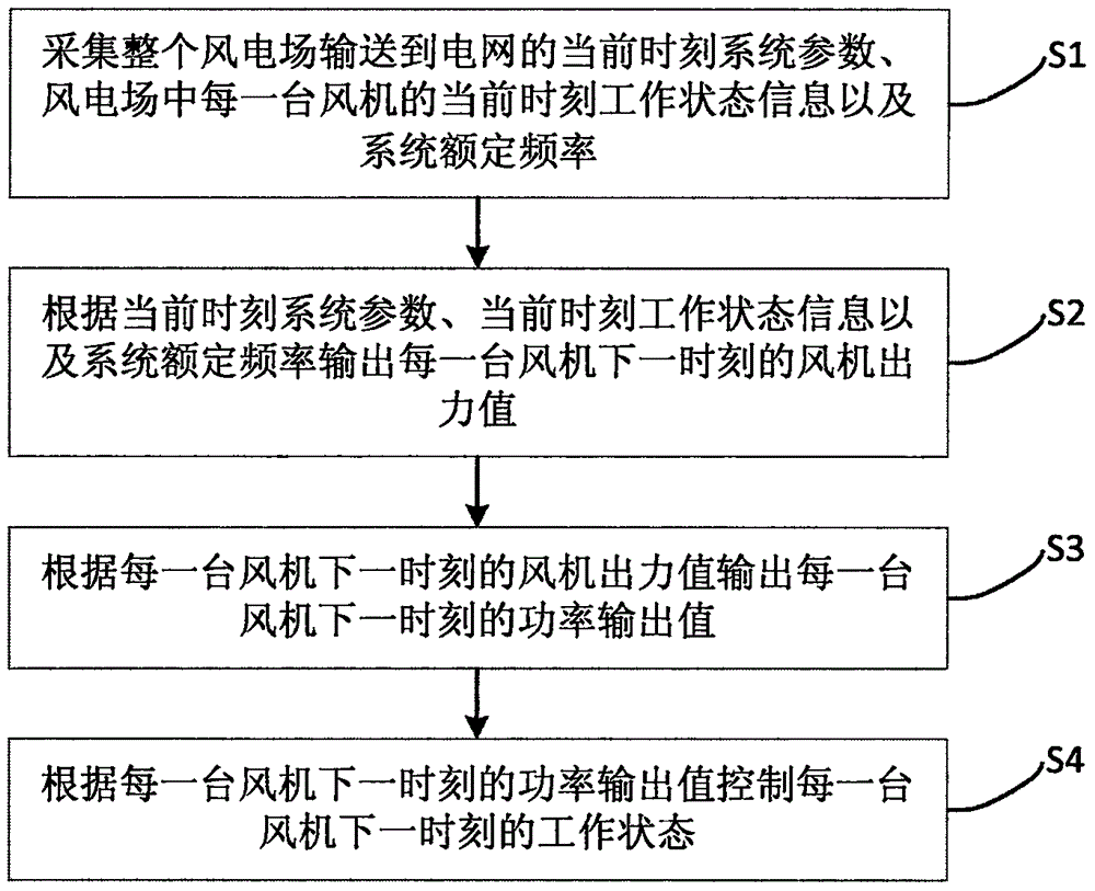
in a first aspect of the present invention, a method for controlling a fan is provided, which includes the following steps: collecting system parameters of the whole wind power plant transmitted to a power grid at the current moment, working state information of each fan in the wind power plant at the current moment and rated frequency of the system; outputting the fan output value of each fan at the next moment according to the current moment system parameters, the current moment working state information and the system rated frequency; outputting the power output value of each fan at the next moment according to the fan output value of each fan at the next moment; and controlling the working state of each fan at the next moment according to the power output value of each fan at the next moment.
Optionally, the system parameter comprises a system power output value and a system frequency output value.
Optionally, the operating state information includes a wind turbine rotor angular speed, a wind turbine final angular speed, a pitch angle speed, a linear speed of a wind speed, and a tip speed ratio.
Optionally, the working state of each fan at the next moment is controlled according to the maximum power tracking algorithm, and the working state at the next moment is the optimal output power state of the fan under the maximum power tracking algorithm.
Optionally, the step of outputting the fan output value of each fan at the next moment according to the current moment system parameter, the current moment operating state information, and the system rated frequency includes: establishing a wind power plant model of the whole wind power plant; and inputting the current-time system parameters, the current-time working state information and the system rated frequency into the wind power plant model for processing to obtain the fan output value of each fan at the next time.
Optionally, obtaining the fan output value at the next moment by making an objective function to obtain an optimal value, and then determining the fan optimal power output,
ui(k+1)=f[gmin|yi(k+1)-y*|,ui(k)]
wherein u isi(k +1) is a fan output value at the next moment of the ith fan; u. ofi(k) The current fan output value of the ith fan at the current moment is obtained; y isi(k +1) is the system frequency of the ith fan at the next moment; y is*The system nominal frequency.
Optionally, the step of outputting the power output value of each fan at the next moment according to the fan output value of each fan at the next moment includes: establishing a transient model of each fan; and inputting the fan output value of the next moment into the transient model for processing to obtain the power output value of each fan at the next moment.
Alternatively, the transient model is obtained by the following formula,
wherein i is the ith fan; j. the design is a square
rIs the rotational inertia of the fan motor; j. the design is a square
gIs the rotational inertia of the fan impeller; p
a,iThe power of the fan of the ith fan at the current moment; omega
r,iThe speed of a fan rotor of the ith fan at the current moment; omega
g,iThe final fan angular speed of the ith fan at the current moment;
the fan rotor speed of the ith fan at the next moment;
the final fan angular speed of the ith fan at the next moment; mu is an integral coefficient of a fan model PI controller; k is a proportional coefficient of the fan model PI controller; theta
d,iThe pitch angle speed of the ith fan at the current moment;
the pitch angle speed of the ith fan at the next moment; ρ is the air density; r is the fan blade radius; v. of
iThe linear velocity is the linear velocity of the wind speed of the ith fan at the current moment;
the wind energy utilization rate of the ith fan at the current moment is a function of the blade tip speed ratio and the pitch angle.
In a second aspect of the present invention, a fan control system is provided, including: the system comprises a first acquisition module, a second acquisition module and a control module, wherein the first acquisition module is used for acquiring current-time system parameters transmitted to a power grid by a whole wind power plant, current-time working state information of each fan in the wind power plant and system rated frequency; the first processing module is used for outputting a fan output value of each fan at the next moment according to the current moment system parameter, the current moment working state information and the system rated frequency; the second processing module is used for outputting the power output value of each fan at the next moment according to the fan output value of each fan at the next moment; and the third processing module is used for controlling the working state of each fan at the next moment according to the power output value of each fan at the next moment.
Optionally, the first processing module includes: the first processing unit is used for establishing a wind power plant model of the whole wind power plant; and the second processing unit is used for inputting the current-time system parameters, the current-time working state information and the system rated frequency into the wind power plant model for processing to obtain the fan output value of each fan at the next time.
Optionally, the second processing module includes: the third processing unit is used for establishing a transient model of each fan; and the fourth processing unit is used for inputting the fan output value at the next moment into the transient model for processing to obtain the power output value of each fan at the next moment.
In a third aspect of the present invention, a terminal is provided, which includes: at least one processor; and a memory communicatively coupled to the at least one processor; wherein the memory stores instructions executable by the at least one processor to cause the at least one processor to perform the method of any one of the first aspects of the invention.
In a fourth aspect of the invention, there is provided a computer readable storage medium having stored thereon computer instructions which, when executed by a processor, carry out the steps of the method according to any one of the first aspect of the invention.
The technical scheme of the invention has the following advantages:
the invention provides a fan control method, a fan control system, a terminal and a readable storage medium, wherein the method comprises the following steps: collecting system parameters of the whole wind power plant transmitted to a power grid at the current moment, working state information of each fan in the wind power plant at the current moment and rated frequency of the system; outputting the fan output value of each fan at the next moment according to the current moment system parameters, the current moment working state information and the system rated frequency; outputting the power output value of each fan at the next moment according to the fan output value of each fan at the next moment; and controlling the working state of each fan at the next moment according to the power output value of each fan at the next moment. According to the control method, when the system frequency changes, the optimal output value and the optimal power output of each fan are determined according to the working state information of each fan, so that each fan can participate in the adjustment of the system, the primary frequency modulation of the system is met, the stability of the whole system is ensured, and the control accuracy of the fans is improved.
Detailed Description
The technical solutions of the present invention will be described clearly and completely with reference to the accompanying drawings, and it should be understood that the described embodiments are some, but not all embodiments of the present invention. All other embodiments, which can be derived by a person skilled in the art from the embodiments given herein without making any creative effort, shall fall within the protection scope of the present invention.
In the description of the present invention, it should be noted that the terms "center", "upper", "lower", "left", "right", "vertical", "horizontal", "inner", "outer", etc., indicate orientations or positional relationships based on the orientations or positional relationships shown in the drawings, and are only for convenience of description and simplicity of description, but do not indicate or imply that the device or element being referred to must have a particular orientation, be constructed and operated in a particular orientation, and thus, should not be construed as limiting the present invention. Furthermore, the terms "first," "second," "third" and "third" are used for descriptive purposes only and are not to be construed as indicating or implying relative importance.
In the description of the present invention, it should be noted that, unless otherwise explicitly specified or limited, the terms "mounted," "connected," and "connected" are to be construed broadly, e.g., as meaning either a fixed connection, a removable connection, or an integral connection; can be mechanically or electrically connected; the two elements may be directly connected or indirectly connected through an intermediate medium, or may be communicated with each other inside the two elements, or may be wirelessly connected or wired connected. The specific meanings of the above terms in the present invention can be understood in specific cases to those skilled in the art.
In addition, the technical features involved in the different embodiments of the present invention described below may be combined with each other as long as they do not conflict with each other.
The embodiment provides a fan control method, and a flow chart is shown in fig. 1. As a preferred embodiment, the flow chart is shown in fig. 2, and includes the following steps:
s1: and acquiring current-time system parameters transmitted to a power grid by the whole wind power plant, current-time working state information of each fan in the wind power plant and system rated frequency. In this embodiment, the current time system parameter includes a current time system power output value and a current time system frequency output value; of course, in other embodiments, the system parameters at the current moment may also include other parameters, such as voltage fluctuation, harmonic parameters, etc., and may be set reasonably as needed. In this embodiment, the current-time working state information includes a current-time fan rotor angular velocity, a current-time fan final angular velocity, a current-time pitch angle velocity, a current-time linear velocity of the wind speed, and a current-time tip speed ratio; of course, in other embodiments, the operating state information may also include other information, such as voltage, current, harmonic analysis, reactive compensation, etc., and may be set as appropriate as needed. In the embodiment, the rated frequency of the system is set as 50Hz of power frequency; of course, in other embodiments, the system rated frequency may be set to other values, such as 48Hz, 60Hz, etc., as appropriate.
S2: and outputting the fan output value of each fan at the next moment according to the system parameters at the current moment, the working state information at the current moment and the rated frequency of the system.
In the present embodiment, as shown in fig. 2, the step S2 specifically includes steps S21-S22:
s21: and establishing a wind power plant model of the whole wind power plant. In this embodiment, the Model Predictive Control (MPC) is used to establish an MPC Model in the wind farm Model, specifically, a wind farm power allocation algorithm is used; certainly, in other embodiments, the MPC model may also be established by using other power distribution algorithms, such as a wind power prediction-based wind farm hybrid energy storage capacity multi-objective optimization configuration method, and the like, and may be reasonably set as needed; the wind power plant model can also be other models, such as a distributed new energy system model with energy storage, and the like, and can be reasonably set according to needs.
The MPC control is an output power tracking problem, and the control principle is as follows: the relationship between the state quantity, the input quantity and the output quantity of the discrete MPC controller can be expressed as:
x(i+1)=Ax(i)+Bu(i)+Md(i)
y(i)=Cx(i)+Du(i)
wherein x (i +1) is the system state quantity at the next moment; x (i) is the system state quantity at the current moment; y (i) is the system output quantity at the current moment; u (i) is the system input quantity at the current moment; d (i) is the system disturbance amount at the current moment; a is a system state variable coefficient in the MPC state equation; b is a system state input quantity coefficient in the MPC state equation; c is a correlation coefficient of the system output quantity and the system state quantity; d is a correlation coefficient of the system output quantity and the system input quantity; and M is the system disturbance quantity coefficient at the current moment. According to the formula, the system state quantity at the next moment can be obtained according to the system input variable at the current moment and the system state quantity at the current moment, then the output quantity at the next moment can be obtained according to the system state quantity at the next moment, and the system input variable has the function of enabling the output variable to track the reference value of the output variable.
S22: and inputting the current-time system parameters, the current-time working state information and the system rated frequency into the wind power plant model for processing to obtain the fan output value of each fan at the next time.
The relationship between the primary frequency, i.e. frequency f(s), and power p(s) of the power system can be expressed as:
wherein, Δ f is the frequency change of the power system; delta P is a power system power change value; tau is a system first order differential coefficient; k is a radical offIs the first-order integral coefficient of the system; omeganSynchronizing generator angular speed for the power system; δ is the power factor angle.
With the MPC model, the above formula can be written as a form of mathematical expression of the MPC model,
wherein Δ f is the system state output, here representing the power system frequency change; a is1Is a system state variable factor; x is the number offIs a system state variable; b1Is a power system power variation factor; delta P is a power system power change value; a is0Is a system state variable factor in an initial state; b0The power system power variation factor in the initial state.
The MPC control is applied to this embodiment, where u (i) is the system input quantity at the current time corresponding to the current-time output power of each fan, y (i +1) is the system output quantity at the next time corresponding to the system frequency at the next time, and x (i) is the system state quantity at the current time corresponding to the system power output value at the current time of the wind farm, that is, the total power of the wind farm.
In the embodiment, the fan output value at the next moment is obtained by making the following objective function obtain the optimal value, and then the optimal power output of the fan is determined,
ui(k+1)=f[gmin|yi(k+1)-y*|,ui(k)]
wherein u isi(k +1) is a fan output value at the next moment of the ith fan; u. ofi(k) The current fan output value of the ith fan at the current moment is obtained; y isi(k +1) is the system frequency of the ith fan at the next moment; y is*The system nominal frequency. Of course, in other embodiments, the fan output value at the next moment can be obtained by other formulas, and the core is to select a suitable input quantity to make the output quantity y (k) and the reference value y0(k) Has the smallest deviation, i.e. the cost function is optimal, and the cost function is Δ y (k) ═ y (k) — y0(k) Wherein y (k) represents the system frequency, y0(k) And the rated frequency is represented and reasonably set according to needs.
S3: and outputting the power output value of each fan at the next moment according to the fan output value of each fan at the next moment.
In the present embodiment, as shown in fig. 2, the step S3 specifically includes steps S31-S32:
s31: and establishing a transient model of each fan. In this embodiment, the control method of the transient model of the wind turbine is Maximum Power Tracking (MPT) control; of course, in other embodiments, the transient model of the wind turbine may also be other model control methods, such as model algorithm control, dynamic matrix control, and the like, and may be set reasonably as needed. Transient models are shown in fig. 3, including synchronous generator, generator side converter, grid side converter, medium/low voltage transformer and medium voltage system, wind turbine model, aerodynamic model, power model, maximum power tracker, pitch angle control and converter control.
A wind power model: the simulation step length is 5s and real measurement data are adopted, the data are processed in a statistical mode and are transmitted to different fans after spline interpolation; an aerodynamic model: calculating mechanical torque considering factors such as wind speed, pitch angle and angular speed; a dynamic model: the model represents a generator rotor and is gambled in terms of both system complexity and compliance with the overall control system; a maximum power tracker: inputting active power to a power grid side converter, wherein the power is obtained from a lookup table drawn according to corresponding maximum power output of a generator at different speeds; pitch angle control: the angular speed of the rotor is limited, the output power is ensured to be within a normal range, and the effectiveness of the dynamic characteristics of the blades is improved; controlling a converter: the converter on the generator side controls the direct current side voltage and the generator bus side voltage, and the converter on the grid side controls the active power and the reactive power flowing to the grid. The determination of the active power in the normal operating state comes from the maximum power tracker (which also functions as frequency support). In this embodiment, the voltage support of the system by the wind turbine is not taken into account, and thus the reactive power input is also set to zero.
Considering a wind farm with N wind turbines, each comprising a turbine, a generator and a converter, the transient model is obtained by the following formula,
wherein i is the ith fan; j. the design is a square
rIs the rotational inertia of the fan motor; j. the design is a square
gIs the rotational inertia of the fan impeller; p
a,iThe power of the fan of the ith fan at the current moment; omega
r,iThe speed of a fan rotor of the ith fan at the current moment; omega
g,iThe final fan angular speed of the ith fan at the current moment;
the fan rotor speed of the ith fan at the next moment;
the final fan angular speed of the ith fan at the next moment; mu is an integral coefficient of a fan model PI controller; k is a proportional coefficient of the fan model PI controller; theta
d,iThe pitch angle speed of the ith fan at the current moment;
the pitch angle speed of the ith fan at the next moment.
The relationship between the power and the wind speed of each fan is obtained by the following formula,
wherein, Pa,iThe power of the fan of the ith fan at the current moment; ρ is the air density; r is the fan blade radius; v. ofiThe linear velocity is the linear velocity of the wind speed of the ith fan at the current moment; cp(βi,λi) The current time is the wind energy utilization rate of the ith fan, namelyTip speed ratio and pitch angle.
S32: and inputting the output value of the fan at the next moment into the transient model for processing to obtain the power output value of each fan at the next moment.
S4: and controlling the working state of each fan at the next moment according to the power output value of each fan at the next moment. In this embodiment, in order to optimize the total output power of the wind farm, the operating state of each wind turbine at the next moment is controlled under the maximum power tracking algorithm, and the operating state at the next moment is the optimal power output state of a single wind turbine, which can minimize the objective function.
Due to the linear relationship between the frequency variation and the power variation, the cost function can be set to optimize the frequency variation under the condition that the frequency variation is not more than the system limit, namely, the total output power of the wind power plant is optimized, namely
Wherein, P
g,iThe total output power of the wind power plant; omega
g,iThe final fan angular velocity; u. of
iThe output power of a single fan in the MPC wind power plant model is used as an input system state variable;
and the total output power reference value of the wind power plant. When the frequency changes, the power of each local wind power plant can be controlled, the condition that the maximum power tracking is met under the wind speed is determined, the total output power of the wind power plant is optimal, and then the primary frequency modulation of a power grid is completed.
According to the fan control method, when the system frequency changes, the optimal output value and the optimal power output of each fan are determined according to the working state information of each fan, so that each fan can participate in the adjustment of the system, the primary frequency modulation of the system is met, the stability of the whole system is ensured, and the control accuracy of the fans is improved.
The control method provided by the invention is a control technology based on a model, and achieves the function of primary frequency modulation of the whole power system by optimizing the output of each fan of the wind power plant. As shown in fig. 4, the control method is proposed based on a kalman filter and a model predictive control technique, wherein the kalman filter is used to estimate the wind speed, which also introduces a core control of the system based on the optimal control of each fan, and by minimizing a cost function including the boundary condition limit of the system, the optimal working area of each fan can be found and the implementation of the primary frequency modulation function of the system can be satisfied.
The control method comprises the following steps: 1) regarding the whole wind farm as a whole, as shown in fig. 4, the Control method includes a core Controller (MPC Controller) and a core kalman filter (Central KF), wherein the core Controller includes a plurality of local kalman filters (local KFs) and a maximum power tracking Control (MPT), and each local kalman filter controls a wind turbine; 2) with the adoption of wind energy, wind farms are increasingly required to meet different requirements of the system, including the control of active power, and an effective value of the active power is distributed to each wind turbine (as an input quantity) through a core controller according to a wind farm control algorithm; 3) the core controller receives rotor angular velocity measurements, pitch angle angles and deviations (variations) in system frequency and power values delivered to the grid by the entire wind farm. The pitch angle control is independently controlled by a PI controller, which enables the angular speed and the active power to be controlled within a normal range; 4) the control method of the local fan and the local Kalman filter is maximum power tracking, so that the power transmitted to the power grid at a specific rotating speed is an optimal value. Under the condition of normal operation, the core controller is not put into use, the core controller inputs a power reference value for each fan, and the power reference value can be correspondingly changed when in failure; 5) when the system frequency changes, the variable quantity of the input quantity is determined according to the maximum power tracking signal so as to meet the primary frequency modulation of the system. And then, the input signals are transmitted to each local fan according to the calculation result of the wind speed, and the stability of the whole system needs to be ensured. The control strategy can realize that each fan can participate in the regulation of the system disturbance when the system is disturbed. When a large amount of wind power is connected to the system, the control of the power system becomes more and more important. On the other hand, when the system is disturbed and the frequency is too low or too high, the wind power plant can also adjust the system frequency by sending out active power. A model-based optimization control is studied, which utilizes a model predictive control system and effectively combines the judgment of wind conditions to define the influence of the fan on the system frequency control. Different technologies such as a Kalman Filter (KF) and a Model Predictive Control (MPC) are combined to predict the load change of the power system and an actual wind speed range determined by tracking the angle of each fan pitch angle so as to find out the optimal working point of each fan, and then the fan is enabled to adjust the system frequency and reduce the change of the system frequency under the condition of not touching the working limit. The core Kalman filter is used for judging the change of external load, and the local Kalman filter is used for estimating the wind speed and evaluating the transient characteristic of the wind turbine. How the fans in the wind power plant are coupled and coordinated and the output of active power is controlled can be further analyzed through the fan control model shown in fig. 4, so as to improve the influence of disturbance or fault on the system frequency. It can also be seen from fig. 4 that when variables such as wind speed or rotor angular velocity and pitch angle, which cannot be directly measured, occur, the MPC is combined to obtain an estimated value of the above variables and an estimated value of the external power variation by introducing KF, where KF functions to introduce an estimated value whose deviation from the real value can be processed by the system of the KF link when some parameters of the system cannot be directly measured, and finally the error between the estimated value and the real value is within an acceptable range.
The flexibility and the effectiveness of the control method are verified through the simulation condition of the operation of 20 fans, and the stability of the system can still be ensured when the parameters are changed. FIG. 5 is a schematic diagram of the effect of a wind turbine generator set on primary frequency modulation under overload conditions; fig. 6 is a schematic diagram of the power transfer capacity of a wind power plant in an overload situation. As can be seen from fig. 5, the system with coordinated control of the wind farm MPC contributes much less to the primary frequency modulation of the power system than a wind farm without coordinated control between wind turbines when a sudden 50MW overload occurs in the system 30 s. Fig. 6 shows that the wind turbine with the MPC coordination control of the wind farm transmits more power under the overload condition than the wind turbine without the coordination control, and then the wind curtailment rate is reduced.
The embodiment further provides a fan control system, which is used for implementing the implementation manner in the embodiment, and the description of the system is omitted. The term "module" as used below may be a combination of software and/or hardware that implements a predetermined function. While the system described in the embodiments below is preferably implemented in software, implementations in hardware, or a combination of software and hardware are also possible and contemplated.
As shown in fig. 7, in the fan control system provided in this embodiment, a first obtaining module 71 is configured to collect current-time system parameters transmitted to a power grid by a whole wind farm, current-time working state information of each fan in the wind farm, and a system rated frequency; the first processing module 72 is configured to output a fan output value of each fan at a next moment according to the current-moment system parameter, the current-moment working state information, and the system rated frequency; the second processing module 73 is configured to output a power output value of each fan at a next moment according to the fan output value of each fan at the next moment; and the third processing module 74 is configured to control the working state of each fan at the next time according to the power output value of each fan at the next time.
Wherein, the first processing module 72 includes: the first processing unit 721 is configured to establish a wind farm model of the whole wind farm; the second processing unit 722 is configured to input the system parameter at the current time, the working state information at the current time, and the system rated frequency into the wind farm model for processing, so as to obtain a fan output value of each fan at the next time.
The second processing module 73 includes: a third processing unit 731, configured to establish a transient model of each wind turbine; the fourth processing unit 732 is configured to input the fan output value at the next time into the transient model for processing, so as to obtain a power output value of each fan at the next time.
Further functional descriptions of the modules are the same as those of the above embodiments, and are not repeated herein.
The fan control system has the advantage of high control accuracy.
The present embodiment provides a terminal, as shown in fig. 8, including: at least one processor 801, such as a CPU (Central Processing Unit), at least one communication interface 803, memory 804, at least one communication bus 802. Wherein a communication bus 802 is used to enable connective communication between these components. The communication interface 803 may include a Display (Display) and a Keyboard (Keyboard), and the optional communication interface 803 may also include a standard wired interface and a standard wireless interface. The Memory 704 may be a RAM (random Access Memory) or a non-volatile Memory (non-volatile Memory), such as at least one disk Memory. The memory 804 may optionally be at least one memory device located remotely from the processor 801 as previously described. Wherein the processor 801 may be in connection with the system described in fig. 7, a set of program codes is stored in the memory 804, and the processor 801 calls the program codes stored in the memory 804 for executing a fan control method, i.e. for executing the fan control method as in the embodiments of fig. 1 and 2.
The communication bus 802 may be a Peripheral Component Interconnect (PCI) bus or an Extended Industry Standard Architecture (EISA) bus. The communication bus 802 may be divided into an address bus, a data bus, a control bus, and the like. For ease of illustration, only one thick line is shown in FIG. 8, but this is not intended to represent only one bus or type of bus.
The memory 804 may include a volatile memory (RAM), such as a random-access memory (RAM); the memory may also include a non-volatile memory (english: non-volatile memory), such as a flash memory (english: flash memory), a hard disk (english: hard disk drive, abbreviated: HDD) or a solid-state drive (english: SSD); the memory 804 may also comprise a combination of the above-described types of memory.
The processor 801 may be a Central Processing Unit (CPU), a Network Processor (NP), or a combination of a CPU and an NP.
The processor 801 may further include a hardware chip. The hardware chip may be an application-specific integrated circuit (ASIC), a Programmable Logic Device (PLD), or a combination thereof. The PLD may be a Complex Programmable Logic Device (CPLD), a field-programmable gate array (FPGA), a General Array Logic (GAL), or any combination thereof.
Optionally, the memory 804 is also used for storing program instructions. The processor 801 may invoke program instructions to implement the fan control method as shown in the embodiments of fig. 1 and 2 of the present application.
The embodiment of the invention also provides a computer-readable storage medium, wherein computer-executable instructions are stored on the computer-readable storage medium and can execute the fan control method in any method embodiment. The storage medium may be a magnetic Disk, an optical Disk, a Read-Only Memory (ROM), a Random Access Memory (RAM), a Flash Memory (Flash Memory), a Hard Disk (Hard Disk Drive, abbreviated as HDD), a Solid State Drive (SSD), or the like; the storage medium may also comprise a combination of memories of the kind described above.
As will be appreciated by one skilled in the art, embodiments of the present invention may be provided as a method, system, or computer program product. Accordingly, the present invention may take the form of an entirely hardware embodiment, an entirely software embodiment or an embodiment combining software and hardware aspects. Furthermore, the present invention may take the form of a computer program product embodied on one or more computer-usable storage media (including, but not limited to, disk storage, CD-ROM, optical storage, and the like) having computer-usable program code embodied therein.
The present invention is described with reference to flowchart illustrations and/or block diagrams of methods, apparatus (systems), and computer program products according to embodiments of the invention. It will be understood that each flow and/or block of the flow diagrams and/or block diagrams, and combinations of flows and/or blocks in the flow diagrams and/or block diagrams, can be implemented by computer program instructions. These computer program instructions may be provided to a processor of a general purpose computer, special purpose computer, embedded processor, or other programmable data processing apparatus to produce a machine, such that the instructions, which execute via the processor of the computer or other programmable data processing apparatus, create means for implementing the functions specified in the flowchart flow or flows and/or block diagram block or blocks.
These computer program instructions may also be stored in a computer-readable memory that can direct a computer or other programmable data processing apparatus to function in a particular manner, such that the instructions stored in the computer-readable memory produce an article of manufacture including instruction means which implement the function specified in the flowchart flow or flows and/or block diagram block or blocks.
These computer program instructions may also be loaded onto a computer or other programmable data processing apparatus to cause a series of operational steps to be performed on the computer or other programmable apparatus to produce a computer implemented process such that the instructions which execute on the computer or other programmable apparatus provide steps for implementing the functions specified in the flowchart flow or flows and/or block diagram block or blocks.
It should be understood that the above examples are only for clarity of illustration and are not intended to limit the embodiments. Other variations and modifications will be apparent to persons skilled in the art in light of the above description. And are neither required nor exhaustive of all embodiments. And obvious variations or modifications therefrom are within the scope of the invention.