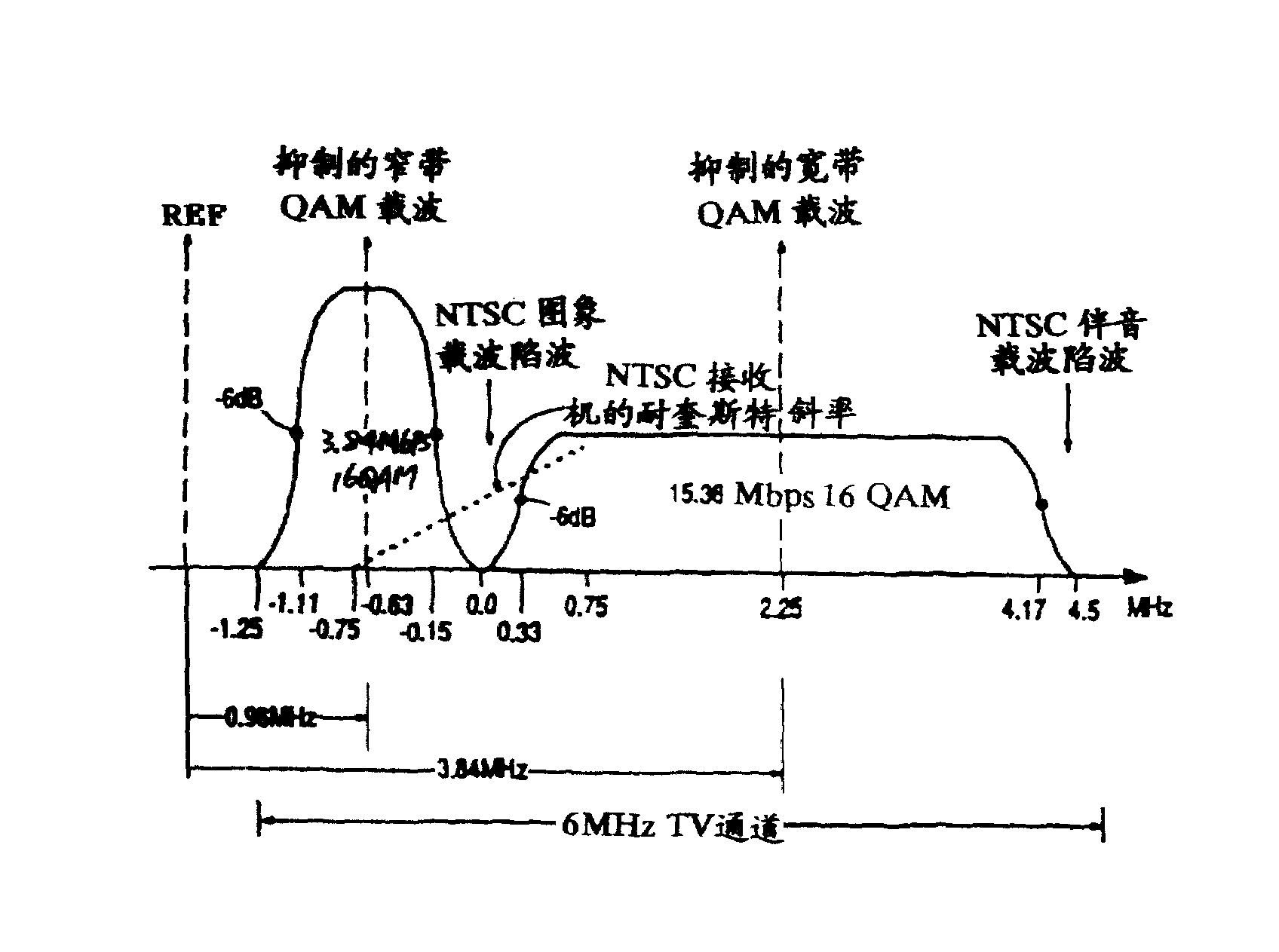
Referring to Fig. 1, wherein show by application number be the HDTV system that proposes in 07/650,329 the aforesaid U.S. Patent application employed, with respect to the 6MHz bandwidth spectrum of a TV passage of the outer reference frequency of band.As shown in the figure, this 6MHz bandwidth comprises the arrowband QAM component that a higher amplitude that is centered close on the reference frequency 0.96MHz suppresses, and this component is used to carry the low frequency video, audio frequency and synchronizing information (being high prior information).Suppressing broadband QAM component than low amplitude and be used to carry high frequency video (promptly low preference information) on 3.84MHz who is centered close to reference frequency.To discuss in detail as following, each continuous 4 bits data set of ongoing per second 3.84 megabits (Mbps) data flow are used for from used one first homophase (I) of arrowband QAM component, select one in the conformation of 16 predetermined points in quadrature (Q) plane.In an identical manner, each continuous 4 bits data set of ongoing per second 15.36 megabits (Mbps) data flow are used for from used one second homophase (I) of broadband QAM component, select one in the conformation of 16 predetermined points in quadrature (Q) plane.
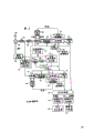
Fig. 2 is the transmitter block diagram that is disclosed in the HDTV system employing of advising in aforementioned the 07/650th, 329 patent application.Fig. 2 illustrates to be used to produce has the transmission of television machine equipment of two QAM signals of the width of cloth-frequent spectrum as shown in Figure 1.From data source 10 and 30 to provide high preferential and low preferential HDTV data with the time axial compression of the 6MHz bandwidth compatibility of the standard NTSC passage figure pattern that contracts.For this reason, data source 10 and 30 includes digital data compression and encoding device, for example comprises huffman coding, run-length coding, the equipment of quantification and discrete cosine transform network.
Be added to an encoder 12 from the signal of data source 10 outputs, this encoder 12 is as the bit converter that is used for flowing from the successive bits that data source 10 receives signal.Encoder 12 will split into 4 bits (symbol) data set of order from the signal of data source 10.Utilize a tracing table with four 4 bit values that occupy each quadrant appointed area, with one 16 value, 4 bits data set are transformed to a four-quadrant signal conformation.Fig. 4 a illustrates the used a kind of like this Bit Allocation in Discrete of 16 bit QAM signal conformations with respect to a four-quadrant grid with reality (I) and empty (Q) quadrature axis.The bit data segment of this conversion comes across the I and the Q output (for example, first dibit occurs at the I output, and next dibit occurs at the Q output) of encoder 12.Next value, promptly 4 bits data set are carried out conversion similarly.In order to make a receiver insensitive for the phase place rotation of a signal conformation that is received, then use a kind of coding form of difference at transmitter, thereby first dibit of each four bit data segment is a phase bits, and this phase bits is selected the residing conformation quadrant of four specific bit data segment.And last dibit is the invariant bit, and they all are identical for each quadrant of four quadrants, and is used for selecting the specified point by that selected quadrant of phase bits.Encoder 32 is operated the signal that receives from low prioritized data source 30 in an identical manner.
Be added to each QAM modulator 14 and 34 of traditional design from the signal of encoder 12 and 32 outputs.Before being added to an input of an addition combiner 18, be transformed to analog form from an arrowband QAM output signal of modulator 14 by a D/A converter 15 by a horizontal low pass filter 16 of 1.5MHz.Filter 16 is removed undesirable high fdrequency component, and this high fdrequency component comprises the harmonic wave that is produced by digital processing formerly in the narrow-band path and steering D/A conversion circuit.Before being added to another input of combiner 18, be transformed to analog form from a broadband QAM output signal of modulator 34 by a D/A converter 35 by a horizontal low pass filter 36 of 6.0MHz and an attenuator 38.Filter 36 is used for identical purpose with filter 16 substantially.38 times of amplitudes of taking advantage of broadband QAM component of attenuator, so as the amplitude than the preferential arrowband of height QAM component of making it low-6db, as shown in Figure 1.Output at combiner 18 produces a Composite Double QAM signal.This pair QAM signal multiply by reference signal REF and produces with signal REF double-side bands higher and low two QAM sideband modulation with the output at modulator 20 in modulator (frequency mixer) 20.6MHz TV channel bandpass filter 22 is got rid of lower sidebands, is used for the upper sideband (Fig. 1) that transmits by the equipment that comprises antenna 25 but kept.
QAM modulator 14 comprises identical square root rised cosine, finite impulse response (FIR) digital filter 41 and 42, and these two digital filters receive I and Q output signal from encoder 12 respectively.Filter 41 is arranged in a common same-phase path and mark is made " I " phase filter, and filter 42 is arranged in a common quadrature phase path and mark is made " Q " phase filter.Filter 41 and 42 has the shape of the non-linear band edge filtration zone of the arrowband that is shown in Fig. 1 and broadband QAM component.Multiplier 44 and 45, modulate respectively from the signal of filter 41 and 42 outputs with cosine and sinusoid fiducial signal.The signal that signal source 46 provides as: with each cycle four 90 ° of intervals, promptly 90 °, 180 °, 270 ° and 360 ° produce tracing tables of sinusoidal and cosine value.The quadrature carrier sinusoidal and the cosine reference signal suppresses corresponding to the arrowband QAM that at 0.96MHz is 3.84Mbps/4 frequency place.Make up to produce high preferential arrowband QAM signal by adder 48 from the quadrature phase modulation output signal of multiplier 44 and 45 outputs.The formation and the class of operation of broadband QAM modulator 34 are similar to modulator 14, be relevant sine and cosine quadrature carrier signal frequency be 3.84MHz.
The timing that utilizes the system shown in Figure 2 that 8 bit digital signal of 2 complement code handle is by the control of numerical data clock signal, and this numerical data clock signal is provided by the frequency synthesizer 52 and 54 of the master clock signal that produces in response to systematic clock generator 55.From a 15.36MHz clock signal of synthesizer 52 data clock as data source 30, encoder 32 and broadband QAM modulator 34.Clock CLK is divided into after the 3.84MHz also data clock as data source 10, encoder 12 and arrowband QAM modulator 14 by a four-divider 58 with frequency, this be since the data transfer rate (3.84Mbps) of narrow band data be wideband data data transfer rate (15.36Mbps) 1/4th.Synthesizer 54 provides a reference signal REF, is used for converting Composite Double QAM signal to the television band signal by frequency mixer 20.
Though the carrier wave that use suppresses makes energy saving and stoped the interference of the certain type in a displayed image, this arrowband and broadband QAM carrier wave do not need to suppress.Non-by a small margin suppressed carrier can be used to provide improved symbol rate clock recovery.QAM carrier wave with asymmetric sideband modulation also is possible.
Referring to Fig. 3, wherein show the receiver block diagram that adopts by the HDTV system that is disclosed in suggestion in the aforesaid U.S. Patent application 07/650,329.As shown in the figure, Fig. 3 represents the television reception machine equipment, and wherein the two QAM signals of a broadcasting that received by antenna 110 are added to a frequency mixer 112 with a reference signal REF, and this reference signal REF has the frequency of the used signal REF of transmitter usually.Comprise and reach difference component from a signal of frequency mixer 112 output.Upper frequency with component by low pass filter 114 filterings, this low pass filter passes through difference component and arrives an analog/digital converter 116.The difference component that passes through presents complex modulated frequency spectrum shown in Figure 1, promptly have the center roughly at the arrowband of 0.96MHz QAM modulation spectrum and center roughly at the broadband of 3.84MHz QAM modulation spectrum.Digital sampling output signal from unit 116 is added to demodulator 118, and demodulator 118 forms an arrowband QAM signal processor together with the unit 120,122,124,126 and 128 that links to each other thereafter.
Demodulator 118 comprises a plurality of input FIR filters, in order to gating arrowband QAM component, and filtering broadband QAM component.Specifically, arrowband qam demodulator 118 comprises a filter, and this filter has a frequency response that the characteristic shape of a frequency conforms to of a modulated arrowband QAM component basic and shown in Figure 1 and answers characteristic curve.Comprise unit 119,121 at one, the demodulator 119 in 123,125,127 and 129 the broadband QAM signal shaping network is selectively by broadband QAM component, and filtering arrowband QAM component.Broadband qam demodulator 119 comprises a filter, and this filter has the response that the width of cloth-the frequency characteristic curve shape conforms to of a modulated broadband QAM component basic and shown in Figure 1.Therefore, this receiver system presents the signal attenuation trap at the frequency place relevant with high-energy information in the standard definition television signal.The unit class of the unit of broadband QAM processor and the corresponding label of the arrowband processor that will discuss below seemingly, just demodulator 118 and 119 characteristic curve are with above-mentioned different.Demodulator 118 and 119 carry out with transmitter (Fig. 2) in modulator 14 and the inverse operation of 34 performed operations.
The adaptive equalizer 120 of traditional design receives demodulated quadrature phase I and Q component from demodulator 118.Equalizer 120 utilizes an adaptive digital FIR filter that comprise amplitude and the phase place scrambling as ghost image that is produced by transmission channel compensated.The equalizer I of 120 outputs and Q signal are added to and produce output I from the unit, an estimation device network 126 of Q component, and this exports I, and Q component is represented I and the very alike estimation of Q component value existing and emission.For example, the noise distortion influence that brings in need be to transmission course in the value of the I of estimation device 126 outputs and Q component is corrected when compensating.The estimation device 126 basic interpretative functions of carrying out one to the sampling apportioning cost, owing to the influence such as noise, the given position in 16 four-quadrant signal conformations can not accurately be fixed in these samplings.Be added to a decoder 122 from the signal of estimation device 126 output, this decoder 122 presents the inverse operation of the performed map function of encoder in transmitter substantially.Utilize 4 bits (symbol) segmentation of tracing table with four-quadrant signal conformation " up conversion " one-tenth order, this 4 bit segments is the binary digit form, in transmitter by unit 12(Fig. 2) just be present in the transmitter before the coding.
The I of error detector 124 monitoring and estimating devices 126, the Q input and output signal has the I that amplitude is proportional to estimation device 126, the output signal of the phase error between the Q input and output signal in order to produce one.This phase error may be because due to the noise effect, in fact phase error will be at random in this case.This phase error also may be because the frequency of signal REF be not equal to due to the frequency of respective signal REF used in the transmitter substantially, and in fact phase error will not be at random in this case.The signal REF frequency that the ERROR signal of exporting from error detector 124 is mainly used in departing from a desired value compensates, and desired value i.e. the frequency values of respective signal REF in transmitter.Especially, this ERROR signal is added to voltage controlled oscillator (VCO) network 128 that also comprises a low pass filter, is used to revise the value of the sinusoidal and cosine reference signal of the quadrature phase modulation that is added on the quadrature demodulator.Sine of having revised and cosine reference signal are changing demodulating process, up to the error span of representing from the output signal of detector 124 demonstrate signal REF all carried out from any frequency shift (FS) of desirable value the compensation till.Low pass filter filters out this ERROR signal relevant with unit 128, so that all in response to such as the error of a nonrandom character of described frequency shift (FS) and adjust, and do not influenced by influence at random such as noise from the baseline signal value of VCO128 and demodulator 118 operation whereby.Comprise that the unit 119,121,127,123 of broadband QAM processor and 129 control loop operate in the mode identical with 128 with the unit 118,120,126,124 of arrowband discussed above QAM processor.The additional information that relates to a control loop operation that includes estimation device 126, detector 124, VCO128 and demodulator 118 types can find (Kluwer Academic Publishers in " digital communication " text of Lee and Messerschmitt, Boston, MA, USA, 1988).
A Direct Digital Frequency Synthesizers 126 produces a clock signal clk in response to a master clock signal from systematic clock generator 130, systematic clock generator 130 also provides a clock signal to frequency synthesizer 135, in order to obtain frequency mixer reference signal REF.The frequency of signal REF is usually consistent with the signal REF that uses in the transmitter.The frequency of signal REF from any skew of desirable frequency all by being compensated as mentioned above.From the signal CLK of signal source 126 outputs are clock signals, are used for the unit 119,121,125 and 127 of broadband processor.Processor processing signal in arrowband with broadband signal 1/4th bandwidth.Therefore, arrowband processor unit and a clock signal clk with clock signal clk 1/4th frequencies/4 responses, clock signal clk/4 are provided by frequency divider 136.The frequency of the clock signal clk in the receiver conforms to the frequency of the middle clock signal clk that adopts of transmitter (Fig. 2).By the information acquisition receiver clock signal from be included in the high-energy arrowband QAM component that receives more reliably, make that establishing suitable receiver clock frequency becomes more convenient.Especially, the compound QAM signal of LPF114 output is added to a nonlinear properties generator 133, Nth power power generator for example, N can be 2 or 4 herein.Unit 133 produces a single-frequency component with the symbol rate of arrowband QAM component.In this case, this symbol rate is 0.96MHz, promptly 1/4th of bit rate.Unit 133 also produces the output signal of a high decay with the symbol rate of low-yield broadband QAM component, its output signal is omitted by signal processing unit subsequently.Phase detectors 137 are in response to 133 the 0.96MHz output component from the unit, and with a low pass filter 138, synthesizer 126 and 16 frequency dividers 139 form a phase-locked loop together jointly.Filter 138 is removed the parasitic frequency that comprises the noise that is produced by the operation of nonlinear properties generator 133.Frequency divider 139 receives a 15.36MHz signal from synthesizer 126, and provides a 0.96MHz output signal to a control input end of phase detectors 137.Synthesizer 126 comprises a register, and the speed accumulation that the signal frequency of self-clock generator 130 is determined since this register is added to the determined phase increment of signal of a control input end of unit 126 by filter 138.The phase value of this accumulation is to a ROM addressing, and this ROM comprises synthetic sine value from unit 126 output signals.The function of unit 126 can be realized by the Q2334 type integrated circuit (by Qualcomm Corporation of San Diego, California makes) of commercial applications.
Signal processor 140 combinations are heightened the prioritized data signal and are turned down the prioritized data signal from separating of decoder 125 from separating of decoder 122.Processor 140 can comprise such as the data of huffman decoder and inverse DCT and removes compression network, the error correction network, and multichannel decomposes and the signal combination network, so that the Voice ﹠ Video TV signal component of separation to be provided.Audio component was handled by an audio signal processor 142 before being added to audio player 146.Video component is handled an image display signal that is added to image display apparatus 148 with generation by unit 144.
QAM encoder by the HDTV transmitter of the present invention imagination adopts 32 conformations (shown in Fig. 5 a), rather than 16 conformations (shown in Fig. 4 a) of being adopted of the QAM encoder 12 of HDTV transmitter shown in Figure 2, receiver detects and the ability of correct transmission chance error difference so that increase significantly.On the other hand, the transmitter by the present invention's imagination is similar to above-mentioned transmitter shown in Figure 2 substantially.But, be diverse 32 conformations (shown in Fig. 5 a) being carried out Bit Allocation in Discrete principle that adopts and the principle of 16 conformations (shown in Fig. 4 a) being carried out the Bit Allocation in Discrete employing.
As mentioned above, the Bit Allocation in Discrete principle that adopts of 16 of Fig. 4 a conformations makes a receiver insensitive to the phase place rotation of the signal conformation that received.Especially, shown in Fig. 4 a, determine I, a different quadrant in 4 quadrants on Q plane by each value of 4 definite binary values of 2 most significant bits (phase bits) in each of 4 bit data segment of 16 signs.Therefore, with I, Q plane half-twist, 180 ° or 270 ° will correspondingly change the position of 4 quadrants.Yet, shown in Fig. 4 a, each value by 4 definite binary values of 2 minimum effective bits (invariant bit) in each of 4 bit data segment of 16 signs, determine one group of 4 a different set of constellation points in the constellation points, this 4 constellation points all is identical to each of 4 quadrants.In addition, the binary value of the invariant bit of each group of 4 groups of constellation points carries out symmetry to be arranged, so as they with I, Q plane half-twist, the relative position in the quadrant of 180 ° or 270 ° responses does not change.Therefore, each the phase bits that Here it is is used for distinguishing 4 quadrants is distributed, and is used to make the signal conformation that is received to the phase place half-twist, and 180 ° or 270 ° are insensitive.
Comprise that by utilization it is clearly that 5 bit data segment of 2 phase bits and 3 invariant bits can expand to 32 conformations with applied Bit Allocation in Discrete principle.In this case, 2 phase bits will be used as each of 4 quadrants of difference, and each of 8 binary values of 3 invariant bits will be determined one group of 8 one group of different constellation points in the constellation points, and this 8 constellation points all is identical to each of 4 quadrants.
Transmission noise and other phenomenon may make the I that is received, the I of the constellation points in the Q plane and Q value from the I that is launched, some departs from corresponding I of the constellation points in the Q plane and Q value, thus the introducing error.Just for this reason, above-mentioned HDTV receiver as shown in Figure 3 comprises the unit 120,124,126 and 128 that carries out error correction for the output signal of demodulator 118.This error correction unit in receiver is operated under following supposition situation, this supposition situation is: at I, the I of the constellation points that has in the Q plane and received, the immediate I of Q value, the specific point in 16 constellation points of Q value is corresponding to a point in the constellation points of being launched.Yet, if the transmission noise will be enough to make the constellation points I in 16 constellation points of Fig. 4 a that is received, the Q value approaches the I of the adjacent constellation points of the correct constellation points corresponding to being launched most, the Q value, rather than correct, corresponding to the I of the constellation points of being launched itself, the Q value, then be used for demodulator 118 such as unit 120,124,126 and 128 equal error means for correctings can not be proofreaied and correct this type of error.
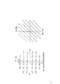
By 32 conformations shown in Fig. 5 a and the 5b being used a kind of Bit Allocation in Discrete of novelty, the invention enables is enough to make the I that is received, and conformation I in the Q plane and Q value approach to become possibility with the adjacent constellation points I of the constellation points correspondence of being launched and the transmission error correction of Q value most.
Fig. 5 a and 5b express at I, include a conformation of 32 in the Q plane, I, the Q plane be arranged in by one-3 and+I value between 3 and one-3 and+one 6 * 6 square grid that the array of Q value between 3 limits in.There is not constellation points to occupy the I at four angles of this square grid, Q point+3 ,+3; + 3 ,-3;-3 ,-3 and-3 ,+3.32 conformations of Fig. 5 a and 5b are divided into 16 segmentation A constellation points (being represented by the white circle among Fig. 5 a) and 16 segmentation B constellation points (being represented by the stain among Fig. 5 a).Each burble point of these 32 conformations is determined by one that comprises 2 phase bits and 3 invariant bits 5 unique bit data segment, wherein, wherein, the low effective phase bits (each the 5 Bit data left sides, second bit) that belongs to all 16 constellation points of segmentation A has binary value 0, and the low effective phase bits that belongs to all 16 constellation points of segmentation B has binary value 1.Shown in Fig. 5 b, the corresponding constellation points of segmentation A and B is arranged on the alternate object line, so that make I, those constellation points that Q plane middle distance approaches any constellation points of A segmentation most belong to the B segmentation, and at I, those constellation points that Q plane middle distance approaches any constellation points of B segmentation most belong to the A segmentation.By this way, at I, the distance in the Q plane between two adjacent A segmentation constellation points and at I, the distance in the Q plane between two adjacent B segmentation constellation points all is maximum.
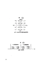
Referring now to Fig. 4 b,, the method of its expression is: each 4 continuous bits data set of an ongoing information bit data stream one after the other are added to the transmitter coding device 12 of Fig. 2 as an input, and the method that Fig. 5 C represents is: each 9 continuous Bit data of an ongoing information bit data stream one after the other are added to the transmitter coding device that uses encoding scheme of the present invention as an input.
Be a pair of continuous data set of an ongoing data bit flow shown in Fig. 4 b, be denoted as 4 bits data set 1 and 4 bits data set 2 respectively.Encoder 12 among Fig. 2 of employing differential coding is in response to the 2 △ phase bits that comprise each data set in data set 1 and 2 and 2 invariant bits, in order to one of 4 bit data segment of selecting Fig. 4 a and 16 conformations, Fig. 4 a is relevant with the constellation points of being launched by QAM.Or rather, the information relevant with each 4 bits data set is determined the I that 4 Bit datas are intersegmental, the I in the Q plane, Q vector distance.4 bit data segment are relevant with current constellation points of launching with the constellation points of formerly being launched by QAM.Encoder 12 includes suitable storing apparatus, tracing table and can be with the 2 △ phase bits of data set and mould 4 adding devices of 2 invariant bit additions, the current constellation points that data set is relevant with 4 bit data segment that are transmitted into and store is relevant, and 4 bit data segment are relevant with the constellation points of emission formerly, thereby select 4 bit data segment relevant with the current constellation points of being launched.The decoder 122 of the receiver among Fig. 3 utilizes mould 4 substracting units, be used for deducting and relevant 4 bit data segment of storage of constellation points that formerly receive, in receiver, to recover 2 △ phase bits and 2 invariant bits of ongoing data bit flow from 4 bit data segment relevant with the current constellation points that receives.
Can understand that from the differential coding scheme of above-mentioned Fig. 4 b the information relevant with each the continuous data group in the data bit flow is separate fully.Therefore, this encoding scheme is not provided at the method that detects or proofread and correct a transmission error in the receiver, in transmission error, noise makes an I who is received, I in the Q plane, it is more approaching that the Q point is compared to the constellation points itself of being launched for a point in 16 conformations of contiguous constellation points of being launched.
A transmitter coding device of the present invention is right continuously in response to each of 9 bits data set of an ongoing data bit flow, continuously to being denoted as 9 bit A 1 and A2 data set and 9 bit B1 and B2 data set respectively.This encoder that also adopts Differential video coding method usually and the encoder 12 and 32 of Fig. 2 similar, but aspect the details of some difference.Especially, encoder of the present invention utilizes three A1 invariant bits, and come together to select 5 bit data segment relevant with specific A segmentation constellation points with the first and the 3rd bit in three △ phase bits, shown in Fig. 5 a, this A segmentation constellation points is by first emission.Then, this encoder utilizes three A2 invariant bits, and with three △ phase bits in the second and the 3rd bit come together to select with by the second specific 5 relevant bit data segment of A segmentation constellation points that send.First and second bits in three △ phase bits correspond respectively to higher effective phase bits of 5 bit data segment relevant with the A segmentation constellation points of first and second emissions, and the 3rd bit in three △ phase bits is corresponding to low effective phase bits of 5 bit data segment all relevant with the A segmentation constellation points of first and second emissions.Therefore, with all relevant three the △ phase bits of A segmentation constellation points of first and second emissions in the 3rd bit have binary value 0.
With similar method, encoder of the present invention utilizes three B1 invariant bits, and select 5 bit data segment relevant together jointly with specific B segmentation constellation points with the first and the 3rd bit in three △ phase places, this B segmentation constellation points is by the 3rd emission.Then, this encoder utilizes three B2 invariant bits, and selects specific 5 bit data segment relevant with B segmentation constellation points together jointly with the second and the 3rd bit in three △ phase bits, and this B segmentation constellation points is by the 4th emission.First and second bits of three △ phase bits correspond respectively to the higher effective phase bits with relevant 5 bit data segment of B segmentation constellation points of third and fourth emission, and the 3rd bit in three △ phase bits is corresponding to low effective phase bits of 5 bit data segment all relevant with the B segmentation constellation points of third and fourth emission.Therefore, with all relevant three the △ phase bits of B segmentation constellation points of third and fourth emission in the 3rd bit have a binary value 1.
Description from the front to Fig. 5 C will understand, being shown in the selected segmentation A in 32 conformations of Fig. 5 a and 5b and the redundant sequence that is transmitting of segmentation B constellation points is series ... A, A, B, B, A, A, B, B, A, A, B ..., this just prior known ongoing transmitting redundancy sequence in receiver makes the QAM decoder in receiver become possibility to following situation, promptly (1) begins to make receiver and transmitter synchronous, and (2) are detected and correct transmission errors after error may take place.
Suppose to have no idea when receiver begins to know following situation, promptly whether the transmission that each received in the transmission that receives in succession is first, second, the transmission of the 3rd or the 4th emission, also suppose following situation in addition, promptly since the transmission noise, the I that is received, the transmission value in the Q plane is all different with 32 all constellation points.So, problem is to determine in receiver that two first any given right transmission of transmitting continuously more may be A segment transmissions or all more may be B segment transmissions.Decoder in the receiver is made this decision according to following substep process, and it can be realized with the form of a microprocessor program.
1. the I of nearest segmentation A constellation points and Q value are found and store I in given right first transmission that receives, in the Q plane on the I of acceptance point and the Q value.To interconnect the then I of this acceptance point vector and Q distance and phase value calculates and stores nearest segmentation A constellation points.
2. the I of nearest segmentation B constellation points and Q value are found and store the given first right I that receives in the transmission, in the Q plane on the I of acceptance point and the Q value.To interconnect the then I of this acceptance point vector and Q distance and phase value calculates and stores nearest segmentation B constellation points.
3. the I of nearest segmentation A constellation points and Q value are found and store the given second right I that receives in the transmission, in the Q plane on the I of acceptance point and the Q value.To interconnect the then I of this acceptance point vector and Q distance and phase value calculates and stores nearest segmentation A constellation points.
4. the I of nearest segmentation B constellation points and Q value are found and store the given second right I that receives in the transmission, in the Q plane on the I of acceptance point and the Q value.To interconnect the then I of this acceptance point vector and Q distance and phase value calculates and stores nearest segmentation B constellation points.
5. calculate the segmentation A vector in step 1 and 3, obtain vector and.
6. calculate the segmentation B vector in step 2 and 4, obtain vector and.
If segmentation A vector and less than segmentation B vector and, the then given right first transmission segmentation that receives is exactly segmentation A; If segmentation A vector and greater than segmentation B vector and, the then given right first transmission segmentation that receives is exactly segmentation B.
Each that this program is added to continuous initial transmission just will determine in succession to last whether the transmission series that is received constitutes the AABB data set of a series of repetitions; The ABBA data set that repeats; The BBAA data set that repeats or the BAAB data set of repetition.If the data set of this repetition is not AABB data set (its expression correct synchronously), thereby the series that is then received can be skipped correct synchronous of acquisitions (perhaps, if lost synchronously, regaining).Obviously, any interruption in the prior known sequences of the transmission series that is received all is illustrated in a transmission error in the given transmission, is omitted in the specific constellation points that it will be launched in determining this given transmission.
Shown in Fig. 4 b, utilize two 4 continuous bits data set (promptly ading up to 8 bits), the difference that can launch is 2 to the sum of constellation points
8, promptly 256.Shown in Fig. 5 c, the different sums to constellation points that utilize 9 single bit A 1 and A2 data set or 9 single bit B1 and B2 data set to launch also are 2
8, promptly 256.Yet the application of this added bit provides the QAM with a large amount of anti-transmission errors transmitter and receiver in encoding scheme of the present invention.
Principle of the present invention is not limited to following the transmission of the repetition series of two A segmentation constellation points by two B segmentation constellation points, and can expand to the repetition series of being followed three or more A segmentation constellation points by three or more B segmentation constellation points.In addition, principle of the present invention also is not limited to 32 conformations shown in Fig. 5 a and the 5b, includes 2 and can expand to
N-1+ 1 and 2
nBetween other rotation symmetry conformation of constellation points, n is one and has the integer that is at least 4 value herein.Yet in all situations, the binary value of minimum effective phase bits is used in the constellation points that belongs to the A segmentation and belongs between the constellation points of B segmentation distinguish.