CN108088570B - A Radiometer Imaging Method Based on Phased Array Scanning System - Google Patents
A Radiometer Imaging Method Based on Phased Array Scanning System Download PDFInfo
- Publication number
- CN108088570B CN108088570B CN201611038354.0A CN201611038354A CN108088570B CN 108088570 B CN108088570 B CN 108088570B CN 201611038354 A CN201611038354 A CN 201611038354A CN 108088570 B CN108088570 B CN 108088570B
- Authority
- CN
- China
- Prior art keywords
- phased array
- radiometer
- array antenna
- power supply
- millimeter wave
- Prior art date
- Legal status (The legal status is an assumption and is not a legal conclusion. Google has not performed a legal analysis and makes no representation as to the accuracy of the status listed.)
- Active
Links
- 238000003384 imaging method Methods 0.000 title claims abstract description 20
- 238000012360 testing method Methods 0.000 claims abstract description 12
- 238000000034 method Methods 0.000 claims description 7
- 230000006641 stabilisation Effects 0.000 claims description 3
- 238000011105 stabilization Methods 0.000 claims description 3
- 230000005284 excitation Effects 0.000 abstract description 2
- 230000005855 radiation Effects 0.000 description 3
- 238000010998 test method Methods 0.000 description 3
- 238000005259 measurement Methods 0.000 description 2
- 238000010586 diagram Methods 0.000 description 1
- 230000035945 sensitivity Effects 0.000 description 1
Images
Classifications
-
- G—PHYSICS
- G01—MEASURING; TESTING
- G01J—MEASUREMENT OF INTENSITY, VELOCITY, SPECTRAL CONTENT, POLARISATION, PHASE OR PULSE CHARACTERISTICS OF INFRARED, VISIBLE OR ULTRAVIOLET LIGHT; COLORIMETRY; RADIATION PYROMETRY
- G01J5/00—Radiation pyrometry, e.g. infrared or optical thermometry
- G01J5/10—Radiation pyrometry, e.g. infrared or optical thermometry using electric radiation detectors
-
- G—PHYSICS
- G01—MEASURING; TESTING
- G01J—MEASUREMENT OF INTENSITY, VELOCITY, SPECTRAL CONTENT, POLARISATION, PHASE OR PULSE CHARACTERISTICS OF INFRARED, VISIBLE OR ULTRAVIOLET LIGHT; COLORIMETRY; RADIATION PYROMETRY
- G01J5/00—Radiation pyrometry, e.g. infrared or optical thermometry
- G01J5/80—Calibration
Landscapes
- Physics & Mathematics (AREA)
- General Physics & Mathematics (AREA)
- Spectroscopy & Molecular Physics (AREA)
- Radiation Pyrometers (AREA)
Abstract
本发明公开了一种基于相控阵扫描体制的辐射计成像方法,包括:控制计算机(1)、毫米波辐射计(2)、直流电源Ⅱ(3)、直流电源Ⅲ(4)、相控阵天线(5)、直流电源I(6)、毫米波噪声头(7)和精密衰减器(8)。在直流电源I的+28V直流电压激励下,毫米波噪声头在所需毫米波段产生准确标定的噪声温度输出,经过毫米波手动调节精密衰减器输出所需的噪声温度。控制计算机(1)控制相控阵天线波束切换,进行二维图像采集和存储。本发明与传统辐射计成像方法相比,只需一根辐射计,且无需伺服机构,具有设备简单、操作简便、测试等效噪声温度可调等优点。

The invention discloses a radiometer imaging method based on a phased array scanning system, comprising: a control computer (1), a millimeter wave radiometer (2), a DC power supply II (3), a DC power supply III (4), a phase control array antenna (5), DC power supply I (6), millimeter wave noise head (7) and precision attenuator (8). Under the excitation of the +28V DC voltage of the DC power supply I, the millimeter-wave noise head generates an accurately calibrated noise temperature output in the required millimeter-wave band, and the precision attenuator outputs the required noise temperature through the millimeter-wave manual adjustment. The control computer (1) controls the beam switching of the phased array antenna, and performs two-dimensional image acquisition and storage. Compared with the traditional radiometer imaging method, the invention only needs one radiometer and does not need a servo mechanism, and has the advantages of simple equipment, simple operation, adjustable test equivalent noise temperature, and the like.
Description
技术领域technical field
本发明涉及一种辐射计成像方法,特别是一种基于相控阵扫描体制的辐射计成像方法。The invention relates to a radiometer imaging method, in particular to a radiometer imaging method based on a phased array scanning system.
背景技术Background technique
单一辐射计只能对指向点反馈温度信号,若要使用辐射计在二维平面内成像,目前主要使用多个辐射计组成的辐射计阵列和运动伺服机构完成的,辐射计的数量决定了一个维度的分辨率,运动伺服的运动幅度决定了另一个维度。这种方法需要较多的辐射和专用运动机构,成本较高,多辐射计之间存在温度漂移,定标复杂,而且成像范围和分辨难以改变。这种测试方法存在测试设备及测试环境复杂、对辐射源温度一致性要求高、测试时间长、效率低等问题。A single radiometer can only feed back the temperature signal to the pointing point. To use a radiometer to image in a two-dimensional plane, it is mainly done by using a radiometer array composed of multiple radiometers and a motion servo mechanism. The number of radiometers determines one. The resolution of the dimension, the magnitude of the motion of the motion servo determines another dimension. This method requires more radiation and a dedicated motion mechanism, the cost is high, there is temperature drift between multiple radiometers, the calibration is complicated, and the imaging range and resolution are difficult to change. This test method has problems such as complex test equipment and test environment, high requirements for the temperature consistency of the radiation source, long test time, and low efficiency.
发明内容SUMMARY OF THE INVENTION
本发明目的在于提供一种基于相控阵扫描体制的辐射计成像方法,解决采用传统测试方法辐射计之间温度一致性要求高、测试流程复杂、测试时间长、效率低的问题。The purpose of the present invention is to provide a radiometer imaging method based on a phased array scanning system, which solves the problems of high temperature consistency requirements, complex test procedures, long test time and low efficiency between radiometers using the traditional test method.
一种基于相控阵扫描体制的辐射计成像方法,其具体步骤为:A radiometer imaging method based on a phased array scanning system, the specific steps are:
第一步搭建基于相控阵扫描体制的辐射计成像系统The first step is to build a radiometer imaging system based on a phased array scanning system
基于相控阵扫描体制的辐射计成像系统,包括:控制计算机、毫米波辐射计、直流电源Ⅱ、直流电源Ⅲ、相控阵天线、直流电源I、毫米波噪声头和精密衰减器。The radiometer imaging system based on phased array scanning system includes: control computer, millimeter wave radiometer, DC power supply II, DC power supply III, phased array antenna, DC power supply I, millimeter wave noise head and precision attenuator.
直流电源I的28V电压输出端与毫米波噪声头的输入端连接;毫米波噪声头的噪声温度输出端与精密衰减器的输入端连接;精密衰减器的输出端与毫米波辐射计的输入端连接;毫米波辐射计的输出端与相控阵天线连接;直流电源Ⅱ的输出端与毫米波辐射计的直流偏置端连接。直流电源Ⅱ的输出电压调节范围为0-25V,直流电源Ⅲ的输出电压56V。The 28V voltage output end of the DC power supply I is connected to the input end of the millimeter wave noise head; the noise temperature output end of the millimeter wave noise head is connected to the input end of the precision attenuator; the output end of the precision attenuator is connected to the input end of the millimeter wave radiometer The output end of the millimeter wave radiometer is connected with the phased array antenna; the output end of the DC power supply II is connected with the DC bias end of the millimeter wave radiometer. The output voltage adjustment range of DC power supply II is 0-25V, and the output voltage of DC power supply III is 56V.
其中控制计算机内包含采集控制模块,采集控制模块的功能为:控制相控阵天线波束切换,进行二维图像采集和存储。The control computer includes an acquisition control module, and the functions of the acquisition control module are: controlling the beam switching of the phased array antenna, and performing two-dimensional image acquisition and storage.
第二步开机预热与稳定工作状态The second step is to warm up and stabilize the working state
进行开机预热稳定操作,设定所需电压值,并连接到相应的偏置端口。待毫米波辐射计、三个直流电源和相控阵天线工作状态稳定后,再进行测试流程。Perform power-on preheat stabilization operation, set the required voltage value, and connect to the corresponding bias port. After the millimeter-wave radiometer, the three DC power supplies and the phased array antenna are in stable working conditions, the test process can be carried out.
第三步确定扫描点数与坐标The third step determines the number of scanning points and coordinates
根据扫描间隔角度确定毫米波辐射计扫描图像的方位向坐标与俯仰向坐标。设扫描间隔为θ,方位向与俯仰向扫描角度范围分别为α、β。则方位向、俯仰向扫描点数m、n分别为The azimuth and elevation coordinates of the scanned image of the millimeter-wave radiometer are determined according to the scanning interval angle. Suppose the scanning interval is θ, and the scanning angle ranges in azimuth and elevation directions are α and β, respectively. Then the scanning points m and n in the azimuth and elevation directions are respectively

其中[]表示向下取整。每点坐标分别为Where [ ] means round down. The coordinates of each point are

第四步采集控制模块标定毫米波辐射计与相控阵天线The fourth step is to calibrate the millimeter wave radiometer and the phased array antenna by the acquisition control module
采集控制模块进行毫米波辐射计与相控阵天线标定。将相控阵天线对准70℃高温恒温源,采集得到70℃高温恒温源定标数据vecHot[mn];然后将相控阵天线对准-10℃低温恒温源,采集得到-10℃低温恒温源定标数据vecCold[mn];得低温平均值:The acquisition control module calibrates the millimeter wave radiometer and the phased array antenna. Aim the phased array antenna at the 70°C high temperature constant temperature source, and collect the calibration data vecHot[mn] of the 70°C high temperature constant temperature source; then align the phased array antenna with the -10°C low temperature constant temperature source, and collect the -10°C low temperature constant temperature Source calibration data vecCold[mn]; get low temperature average:

AveCold:低温平均值;AveCold: low temperature average;
vecCold[i]:第i路低温数值;vecCold[i]: the i-th low temperature value;
高温与低温差值平均值:The average value of the difference between high temperature and low temperature:

DiffAve:高温与低温差值平均值;DiffAve: the average value of the difference between high temperature and low temperature;
vecHot[i]:第i路高温数值;vecHot[i]: high temperature value of the i-th road;
第五步标定目标图像The fifth step is to calibrate the target image
采集目标图像,得到图像数据OriginalData[mn],最后对目标图像进行定标补偿,对每一毫米波辐射计点进行单独补偿:Collect the target image, obtain the image data OriginalData[mn], and finally perform calibration compensation on the target image, and perform separate compensation for each millimeter-wave radiometer point:
CompensateData[i]:第i路内定标补偿后数据;CompensateData[i]: The data after the i-th internal calibration compensation;
OriginalData[i]:第i路内定标补偿前数据;OriginalData[i]: The data before the i-th internal calibration compensation;
AveCold:低温平均值;AveCold: low temperature average;
DiffAve:高温与低温差值平均值;DiffAve: the average value of the difference between high temperature and low temperature;
最后将CompensateData[i]合成得到补偿后的数据CompensateData[mn],完成内定标。Finally, the CompensateData[i] is synthesized to obtain the compensated data CompensateData[mn], and the internal calibration is completed.
本方法提出了基于相控阵扫描体制的辐射计成像方法,实现了小体积、高测量精度成像和测试时间短的需求。直流电源I供给毫米波噪声头所需的28V直流电压,在28V直流电压的激励下,毫米波噪声头在所需毫米波段产生准确标定的噪声温度输出,经过毫米波手动调节精密衰减器输出所需的噪声温度。毫米波手动调节精密衰减器可以在机箱外部手动旋钮的控制下完成不同衰减量的变化,从而输出不同的噪声温度,该输出噪声温度将作为辐射计温度灵敏度测量的基准。控制计算机中的采集控制模块控制相控阵天线波束切换,进行二维图像采集和存储。本发明提出的辐射计成像方法能够简化测试流程,提高测试效率、降低测试成本。This method proposes a radiometer imaging method based on a phased array scanning system, which meets the requirements of small volume, high measurement accuracy imaging and short test time. The DC power supply I supplies the 28V DC voltage required by the millimeter wave noise head. Under the excitation of the 28V DC voltage, the millimeter wave noise head produces an accurately calibrated noise temperature output in the required millimeter wave band. After the millimeter wave manually adjusts the output of the precision attenuator. desired noise temperature. The millimeter wave manual adjustment precision attenuator can complete the change of different attenuation under the control of the manual knob outside the chassis, so as to output different noise temperatures, which will be used as the benchmark for the temperature sensitivity measurement of the radiometer. The acquisition control module in the control computer controls the beam switching of the phased array antenna, and performs two-dimensional image acquisition and storage. The radiometer imaging method proposed by the invention can simplify the testing process, improve the testing efficiency and reduce the testing cost.
附图说明Description of drawings
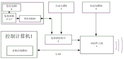
图1一种基于相控阵扫描体制的辐射计成像方法系统组成示意图;Fig. 1 is a schematic diagram of the system composition of a radiometer imaging method based on a phased array scanning system;
1.控制计算机 2.毫米波辐射计 3.直流电源Ⅱ 4.直流电源Ⅲ 5.相控阵天线 6.直流电源I 7.毫米波噪声头 8.精密衰减器1.
具体实施方式Detailed ways
一种基于相控阵扫描体制的辐射计成像方法,其具体步骤为:A radiometer imaging method based on a phased array scanning system, the specific steps are:
第一步搭建基于相控阵扫描体制的辐射计成像系统The first step is to build a radiometer imaging system based on a phased array scanning system
基于相控阵扫描体制的辐射计成像系统,包括:控制计算机1、毫米波辐射计2、直流电源Ⅱ3、直流电源Ⅲ4、相控阵天线5、直流电源I6、毫米波噪声头7和精密衰减器8。Radiometer imaging system based on phased array scanning system, including: control computer 1,
直流电源I6的28V电压输出端与毫米波噪声头7的输入端连接;毫米波噪声头7的噪声温度输出端与精密衰减器8的输入端连接;精密衰减器8的输出端与毫米波辐射计2的输入端连接;毫米波辐射计2的输出端与相控阵天线5连接;直流电源Ⅱ3的输出端与毫米波辐射计2的直流偏置端连接。直流电源Ⅱ3的输出电压调节范围为0-25V,直流电源Ⅲ4的输出电压56V。The 28V voltage output end of the DC power supply I6 is connected with the input end of the millimeter wave noise head 7; the noise temperature output end of the millimeter wave noise head 7 is connected with the input end of the precision attenuator 8; the output end of the precision attenuator 8 is connected with the millimeter wave radiation The input end of the
其中控制计算机1内包含采集控制模块,采集控制模块的功能为:控制相控阵天线5波束切换,进行二维图像采集和存储。The control computer 1 includes an acquisition control module, and the functions of the acquisition control module are: controlling the beam switching of the phased array antenna 5, and performing two-dimensional image acquisition and storage.
第二步开机预热与稳定工作状态The second step is to warm up and stabilize the working state
进行开机预热稳定操作,设定所需电压值,并连接到相应的偏置端口。待毫米波辐射计2、三个直流电源和相控阵天线5工作状态稳定后,再进行测试流程。Perform power-on preheat stabilization operation, set the required voltage value, and connect to the corresponding bias port. After the
第三步确定扫描点数与坐标The third step determines the number of scanning points and coordinates
根据扫描间隔角度确定毫米波辐射计2扫描图像的方位向坐标与俯仰向坐标。设扫描间隔为θ,方位向与俯仰向扫描角度范围分别为α、β。则方位向、俯仰向扫描点数m、n分别为The azimuth and elevation coordinates of the scanned image of the millimeter-

其中[]表示向下取整。每点坐标分别为Where [ ] means round down. The coordinates of each point are

第四步采集控制模块标定毫米波辐射计2与相控阵天线5Step 4: The acquisition control module calibrates the
采集控制模块进行毫米波辐射计2与相控阵天线5标定。将相控阵天线5对准70℃高温恒温源,采集得到70℃高温恒温源定标数据vecHot[mn];然后将相控阵天线5对准-10℃低温恒温源,采集得到-10℃低温恒温源定标数据vecCold[mn];得低温平均值:The acquisition control module calibrates the

AveCold:低温平均值;AveCold: low temperature average;
vecCold[i]:第i路低温数值;vecCold[i]: the i-th low temperature value;
高温与低温差值平均值:The average value of the difference between high temperature and low temperature:
DiffAve:高温与低温差值平均值;DiffAve: the average value of the difference between high temperature and low temperature;
vecHot[i]:第i路高温数值;vecHot[i]: high temperature value of the i-th road;
第五步标定目标图像The fifth step is to calibrate the target image
采集目标图像,得到图像数据OriginalData[mn],最后对目标图像进行定标补偿,对每一毫米波辐射计2点进行单独补偿:Collect the target image, obtain the image data OriginalData[mn], and finally perform calibration compensation on the target image, and perform separate compensation for 2 points of each millimeter-wave radiometer:

CompensateData[i]:第i路内定标补偿后数据;CompensateData[i]: The data after the i-th internal calibration compensation;
OriginalData[i]:第i路内定标补偿前数据;OriginalData[i]: The data before the i-th internal calibration compensation;
AveCold:低温平均值;AveCold: low temperature average;
DiffAve:高温与低温差值平均值;DiffAve: the average value of the difference between high temperature and low temperature;
最后将CompensateData[i]合成得到补偿后的数据CompensateData[mn],完成内定标。Finally, the CompensateData[i] is synthesized to obtain the compensated data CompensateData[mn], and the internal calibration is completed.
Claims (1)


Priority Applications (1)
| Application Number | Priority Date | Filing Date | Title |
|---|---|---|---|
| CN201611038354.0A CN108088570B (en) | 2016-11-23 | 2016-11-23 | A Radiometer Imaging Method Based on Phased Array Scanning System |
Applications Claiming Priority (1)
| Application Number | Priority Date | Filing Date | Title |
|---|---|---|---|
| CN201611038354.0A CN108088570B (en) | 2016-11-23 | 2016-11-23 | A Radiometer Imaging Method Based on Phased Array Scanning System |
Publications (2)
| Publication Number | Publication Date |
|---|---|
| CN108088570A CN108088570A (en) | 2018-05-29 |
| CN108088570B true CN108088570B (en) | 2020-02-21 |
Family
ID=62170710
Family Applications (1)
| Application Number | Title | Priority Date | Filing Date |
|---|---|---|---|
| CN201611038354.0A Active CN108088570B (en) | 2016-11-23 | 2016-11-23 | A Radiometer Imaging Method Based on Phased Array Scanning System |
Country Status (1)
| Country | Link |
|---|---|
| CN (1) | CN108088570B (en) |
Families Citing this family (3)
| Publication number | Priority date | Publication date | Assignee | Title |
|---|---|---|---|---|
| CN109297589A (en) * | 2018-08-28 | 2019-02-01 | 北京遥感设备研究所 | A test system for target radiation characteristics of W-band radiometer |
| CN109490979B (en) * | 2018-11-12 | 2020-05-29 | 北京航空航天大学 | Millimeter wave radiometer array structure suitable for near-field rapid imaging and design method |
| CN112630746B (en) * | 2020-12-01 | 2023-09-15 | 北京遥感设备研究所 | A pulse Doppler lidar for long-range target measurement |
Citations (3)
| Publication number | Priority date | Publication date | Assignee | Title |
|---|---|---|---|---|
| CN1176380A (en) * | 1996-09-12 | 1998-03-18 | Trw公司 | Focal plane array calibration method |
| CN105372610A (en) * | 2015-10-27 | 2016-03-02 | 中国科学院国家空间科学中心 | Four-point scaling device and method for microwave radiometer |
| CN105606906A (en) * | 2015-12-24 | 2016-05-25 | 中国电子科技集团公司第五十四研究所 | Millimeter wave phased array test and calibration method |
Family Cites Families (1)
| Publication number | Priority date | Publication date | Assignee | Title |
|---|---|---|---|---|
| FR3007145B1 (en) * | 2013-06-18 | 2015-07-03 | Microwave Characterization Ct | PORTABLE HYPERFREQUENCY IMAGING DEVICE, SYSTEM COMPRISING SUCH A DEVICE, AND CORRESPONDING IMAGING METHOD |
-
2016
- 2016-11-23 CN CN201611038354.0A patent/CN108088570B/en active Active
Patent Citations (3)
| Publication number | Priority date | Publication date | Assignee | Title |
|---|---|---|---|---|
| CN1176380A (en) * | 1996-09-12 | 1998-03-18 | Trw公司 | Focal plane array calibration method |
| CN105372610A (en) * | 2015-10-27 | 2016-03-02 | 中国科学院国家空间科学中心 | Four-point scaling device and method for microwave radiometer |
| CN105606906A (en) * | 2015-12-24 | 2016-05-25 | 中国电子科技集团公司第五十四研究所 | Millimeter wave phased array test and calibration method |
Non-Patent Citations (1)
| Title |
|---|
| "基于码分复用的相控阵雷达内定标技术";赖光霁;《遥测遥控》;20130715;第34卷(第4期);第6-11页 * |
Also Published As
| Publication number | Publication date |
|---|---|
| CN108088570A (en) | 2018-05-29 |
Similar Documents
| Publication | Publication Date | Title |
|---|---|---|
| CN109541510B (en) | Channel amplitude and phase calibration method and device suitable for array radiometer | |
| CN105353229B (en) | A kind of phased array amplitude phase error Near-Field Calibration Method based on one-dimensional rotation | |
| CN106546827B (en) | A kind of Pattern measurement method, circuit and the system of phased array direction-finding device | |
| CN109581279B (en) | A method and device for correcting direction finding accuracy of an ultra-wideband multi-beam system | |
| CN101483274B (en) | External calibration method for phase variable power detecting array antenna | |
| CN105606906B (en) | A kind of millimeter wave phased array test calibration method | |
| CN108088570B (en) | A Radiometer Imaging Method Based on Phased Array Scanning System | |
| CN109752696B (en) | RCS correction method for corner reflector in high-resolution synthetic aperture radar satellite image | |
| CN106200697A (en) | A kind of radio telescope points to real-time correcting method | |
| CN103675795A (en) | Device and method for automatically matching laser radar receiving and transmitting optical axes | |
| CN110018361B (en) | A method and system for measuring the ratio of gain to noise temperature of a phased array antenna | |
| CN112986701B (en) | Holographic measurement method and system based on radio frequency power supply broadband signal | |
| Hassett | Phased array antenna calibration measurement techniques and methods | |
| CN110470403B (en) | Surface source lunar measurement calibration method suitable for foundation microwave radiometer | |
| CN106291133A (en) | A kind of UHF waveband broadband DBF array antenna method of testing | |
| CN116520035B (en) | A two-dimensional pattern testing method employing a planar near-field fast inversion method | |
| CN112073350B (en) | Phase difference measuring method and system for antenna array and phase compensation method | |
| CN107991675B (en) | An Internal and External Calibration Method for Radiometer Imaging | |
| CN112285659A (en) | A method for on-orbit update of brightness temperature reconstruction matrix based on synthetic aperture radiometer | |
| CN110196401B (en) | Calibration system and method for synthetic aperture phased array microwave radiometer | |
| CN109818688B (en) | An array antenna calibration method, device, system, and computer-readable storage medium | |
| US11899098B2 (en) | System and method for testing a radar under test | |
| CN109818689B (en) | An array antenna calibration method, device, system, and computer-readable storage medium | |
| CN114137489A (en) | Mid-field calibration method for phased array radar antenna | |
| CN116026360B (en) | On-orbit field calibration method for high-orbit large-area array optical remote sensor |
Legal Events
| Date | Code | Title | Description |
|---|---|---|---|
| PB01 | Publication | ||
| PB01 | Publication | ||
| SE01 | Entry into force of request for substantive examination | ||
| SE01 | Entry into force of request for substantive examination | ||
| GR01 | Patent grant | ||
| GR01 | Patent grant |