CN108106295B - Refrigeration device - Google Patents
Refrigeration device Download PDFInfo
- Publication number
- CN108106295B CN108106295B CN201810058654.8A CN201810058654A CN108106295B CN 108106295 B CN108106295 B CN 108106295B CN 201810058654 A CN201810058654 A CN 201810058654A CN 108106295 B CN108106295 B CN 108106295B
- Authority
- CN
- China
- Prior art keywords
- fluid
- fluid reservoir
- reservoir
- temperature
- cooling
- Prior art date
- Legal status (The legal status is an assumption and is not a legal conclusion. Google has not performed a legal analysis and makes no representation as to the accuracy of the status listed.)
- Active
Links
Images


Classifications
-
- F—MECHANICAL ENGINEERING; LIGHTING; HEATING; WEAPONS; BLASTING
- F25—REFRIGERATION OR COOLING; COMBINED HEATING AND REFRIGERATION SYSTEMS; HEAT PUMP SYSTEMS; MANUFACTURE OR STORAGE OF ICE; LIQUEFACTION SOLIDIFICATION OF GASES
- F25D—REFRIGERATORS; COLD ROOMS; ICE-BOXES; COOLING OR FREEZING APPARATUS NOT OTHERWISE PROVIDED FOR
- F25D3/00—Devices using other cold materials; Devices using cold-storage bodies
- F25D3/02—Devices using other cold materials; Devices using cold-storage bodies using ice, e.g. ice-boxes
-
- F—MECHANICAL ENGINEERING; LIGHTING; HEATING; WEAPONS; BLASTING
- F25—REFRIGERATION OR COOLING; COMBINED HEATING AND REFRIGERATION SYSTEMS; HEAT PUMP SYSTEMS; MANUFACTURE OR STORAGE OF ICE; LIQUEFACTION SOLIDIFICATION OF GASES
- F25D—REFRIGERATORS; COLD ROOMS; ICE-BOXES; COOLING OR FREEZING APPARATUS NOT OTHERWISE PROVIDED FOR
- F25D11/00—Self-contained movable devices, e.g. domestic refrigerators
- F25D11/006—Self-contained movable devices, e.g. domestic refrigerators with cold storage accumulators
-
- F—MECHANICAL ENGINEERING; LIGHTING; HEATING; WEAPONS; BLASTING
- F25—REFRIGERATION OR COOLING; COMBINED HEATING AND REFRIGERATION SYSTEMS; HEAT PUMP SYSTEMS; MANUFACTURE OR STORAGE OF ICE; LIQUEFACTION SOLIDIFICATION OF GASES
- F25D—REFRIGERATORS; COLD ROOMS; ICE-BOXES; COOLING OR FREEZING APPARATUS NOT OTHERWISE PROVIDED FOR
- F25D11/00—Self-contained movable devices, e.g. domestic refrigerators
- F25D11/003—Transport containers
-
- F—MECHANICAL ENGINEERING; LIGHTING; HEATING; WEAPONS; BLASTING
- F25—REFRIGERATION OR COOLING; COMBINED HEATING AND REFRIGERATION SYSTEMS; HEAT PUMP SYSTEMS; MANUFACTURE OR STORAGE OF ICE; LIQUEFACTION SOLIDIFICATION OF GASES
- F25D—REFRIGERATORS; COLD ROOMS; ICE-BOXES; COOLING OR FREEZING APPARATUS NOT OTHERWISE PROVIDED FOR
- F25D17/00—Arrangements for circulating cooling fluids; Arrangements for circulating gas, e.g. air, within refrigerated spaces
- F25D17/02—Arrangements for circulating cooling fluids; Arrangements for circulating gas, e.g. air, within refrigerated spaces for circulating liquids, e.g. brine
-
- F—MECHANICAL ENGINEERING; LIGHTING; HEATING; WEAPONS; BLASTING
- F25—REFRIGERATION OR COOLING; COMBINED HEATING AND REFRIGERATION SYSTEMS; HEAT PUMP SYSTEMS; MANUFACTURE OR STORAGE OF ICE; LIQUEFACTION SOLIDIFICATION OF GASES
- F25D—REFRIGERATORS; COLD ROOMS; ICE-BOXES; COOLING OR FREEZING APPARATUS NOT OTHERWISE PROVIDED FOR
- F25D3/00—Devices using other cold materials; Devices using cold-storage bodies
- F25D3/02—Devices using other cold materials; Devices using cold-storage bodies using ice, e.g. ice-boxes
- F25D3/06—Movable containers
-
- F—MECHANICAL ENGINEERING; LIGHTING; HEATING; WEAPONS; BLASTING
- F25—REFRIGERATION OR COOLING; COMBINED HEATING AND REFRIGERATION SYSTEMS; HEAT PUMP SYSTEMS; MANUFACTURE OR STORAGE OF ICE; LIQUEFACTION SOLIDIFICATION OF GASES
- F25D—REFRIGERATORS; COLD ROOMS; ICE-BOXES; COOLING OR FREEZING APPARATUS NOT OTHERWISE PROVIDED FOR
- F25D2303/00—Details of devices using other cold materials; Details of devices using cold-storage bodies
- F25D2303/08—Devices using cold storage material, i.e. ice or other freezable liquid
- F25D2303/085—Compositions of cold storage materials
-
- F—MECHANICAL ENGINEERING; LIGHTING; HEATING; WEAPONS; BLASTING
- F25—REFRIGERATION OR COOLING; COMBINED HEATING AND REFRIGERATION SYSTEMS; HEAT PUMP SYSTEMS; MANUFACTURE OR STORAGE OF ICE; LIQUEFACTION SOLIDIFICATION OF GASES
- F25D—REFRIGERATORS; COLD ROOMS; ICE-BOXES; COOLING OR FREEZING APPARATUS NOT OTHERWISE PROVIDED FOR
- F25D2400/00—General features of, or devices for refrigerators, cold rooms, ice-boxes, or for cooling or freezing apparatus not covered by any other subclass
- F25D2400/32—Removal, transportation or shipping of refrigerating devices from one location to another
Landscapes
- Engineering & Computer Science (AREA)
- Chemical & Material Sciences (AREA)
- Combustion & Propulsion (AREA)
- Physics & Mathematics (AREA)
- Mechanical Engineering (AREA)
- Thermal Sciences (AREA)
- General Engineering & Computer Science (AREA)
- Devices That Are Associated With Refrigeration Equipment (AREA)
- Secondary Cells (AREA)
Abstract
本发明涉及一种制冷设备。其中,一种用于冷却诸如食品、饮料或疫苗的物体的设备,包括至少两个储存器、用于冷却包含在储存器中的一个中的流体的冷却装置,以及在储存器的相应上区域之间的热传递区域。热传递区域容许在包含在储存器中的流体之间的热传递,使得在一个储存器中的流体的冷却导致在另一个储存器中的流体的冷却。
The present invention relates to a refrigeration device. Among them, an apparatus for cooling objects such as food, beverages or vaccines, comprising at least two reservoirs, cooling means for cooling a fluid contained in one of the reservoirs, and a corresponding upper region of the reservoirs heat transfer area between. The heat transfer region allows heat transfer between fluids contained in the reservoirs such that cooling of the fluid in one reservoir results in cooling of the fluid in the other reservoir.
Description
本申请是申请号为201380017447.3、申请日为2013年01月28日、发明名称为“制冷设备”的发明专利申请的分案申请。This application is a divisional application for an invention patent application with an application number of 201380017447.3, an application date of January 28, 2013, and an invention name of "refrigeration equipment".
技术领域technical field
本发明涉及制冷设备。尤其地,但不排他地,本发明涉及制冷设备,其用于在存储及运输疫苗、易腐烂食品、包装饮料等时使用,以及用于在缺少可靠电力供应的情况下,诸如电池的装备的冷却或温度控制。本发明的方面涉及设备且涉及方法。The present invention relates to refrigeration equipment. In particular, but not exclusively, the present invention relates to refrigeration equipment for use in the storage and transport of vaccines, perishable foods, packaged beverages, etc., and for equipment such as batteries in the absence of a reliable power supply Cooling or temperature control. Aspects of the invention relate to apparatus and to methods.
背景技术Background technique
世界人口中的很大比例并不能利用稳定且可靠的干线电源。不发达国家,或远离居民区的区域,经常遭受电功率的限额配给,其通常借助于“甩负荷”(为故意断电的产生或配电网的失效)实施。A large percentage of the world's population does not have access to stable and reliable mains power. Underdeveloped countries, or areas far from residential areas, often suffer from rationing of electrical power, which is usually implemented by means of "load shedding" (either the generation of intentional blackouts or failure of the distribution network).
在这些地区,其中,缺乏恒定和/或可靠的电功率供应限制了常规制冷装备的广泛使用,疫苗、食品和饮料在适宜温度下的存储为困难的。例如,需要疫苗在大约2-8℃之间的窄温度范围内存储,在该温度范围外,它们的成活力可被损害或破坏。关于食物,特别是易腐烂食品以及诸如罐头或瓶装饮品的包装饮料的存储,产生类似问题。In these areas, where the lack of a constant and/or reliable electrical power supply limits the widespread use of conventional refrigeration equipment, the storage of vaccines, food and beverages at suitable temperatures is difficult. For example, vaccines need to be stored within a narrow temperature range between about 2-8°C, outside of which their viability can be compromised or destroyed. Similar problems arise with regard to the storage of food, especially perishable food, and packaged beverages such as canned or bottled beverages.
响应于该问题,本申请人之前已提出一种形式的制冷设备,其在国际专利申请NO.PCT/GB2010/051129中公开,其容许在失去电功率之后,将制冷存储空间维持在4 - 8°C的温度范围内达高达30天。该现有技术设备包括用于疫苗、食品、饮品容器或待冷却的任何其他物品的有效载荷空间,有效载荷空间设置在水的绝热储存器的下区域处。在储存器上方,并且与其流体连通的是,包含冷却元件或低温热质量体的填充水顶部空间,其提供冷水供应至储存器。In response to this problem, the applicant has previously proposed a form of refrigeration equipment, disclosed in International Patent Application No. PCT/GB2010/051129, which allows the refrigeration storage space to be maintained at 4 - 8° after loss of electrical power C temperature range up to 30 days. This prior art device includes a payload space for vaccines, food, drink containers or any other item to be cooled, the payload space being provided at the lower region of the thermally insulated reservoir of water. Above the reservoir, and in fluid communication therewith, is a water-filled headspace containing cooling elements or low temperature thermal masses that provide a supply of cold water to the reservoir.
该现有技术设备依赖于水在大约4℃处处于其最大密度的已知特性。因此,通过在顶部空间中的冷却元件或热质量体冷却至该温度的水倾向于向下下沉到储存器中,安置在围绕有效载荷空间的下区域处,该有效载荷空间通过热传递冷却至处于或接近4℃的温度。This prior art device relies on the known property that water is at its maximum density at about 4°C. Therefore, water cooled to this temperature by cooling elements or thermal mass in the headspace tends to sink down into the reservoir, seated at the lower region surrounding the payload space, which is cooled by heat transfer to a temperature at or near 4°C.
申请人已经确认需要改进以上提到的设备,以便于在一些应用中的包装、运输和效率。本发明针对该背景来构思。本发明的其他目的和优点将从以下描述、权利要求和附图中变得显而易见。Applicants have identified a need to improve the above-mentioned equipment to facilitate packaging, transport and efficiency in some applications. The present invention is conceived against this background. Other objects and advantages of the present invention will become apparent from the following description, claims and drawings.
发明内容SUMMARY OF THE INVENTION
因此,本发明的方面提供了如在所附权利要求中所主张权利的设备和方法。Accordingly, aspects of the present invention provide apparatus and methods as claimed in the appended claims.
根据本发明寻求保护的另一方面,提供一种设备,其包括至少第一和第二流体存储器、用于冷却包含在第一流体储存器中的流体的冷却器件,以及设置在第一和第二流体储存器的相应上区域之间的热传递区域,该热传递区域用于容许在包含在第一流体储存器中的流体与包含在第二流体储存器中的流体之间的热传递。According to another aspect of the present invention for which protection is sought, there is provided an apparatus comprising at least first and second fluid reservoirs, cooling means for cooling the fluid contained in the first fluid reservoir, and a device arranged in the first and second fluid reservoirs A heat transfer area between respective upper areas of the two fluid reservoirs for allowing heat transfer between the fluid contained in the first fluid reservoir and the fluid contained in the second fluid reservoir.
根据本发明寻求保护的又一方面,提供一种设备,其包括:According to yet another aspect of the present invention seeking protection, there is provided a device comprising:
第一和第二流体储存器;first and second fluid reservoirs;
冷却器件,其用于冷却包含在第一流体储存器中的流体;以及a cooling device for cooling the fluid contained in the first fluid reservoir; and
设置在第一和第二流体储存器的相应上区域之间的热传递区域,a heat transfer region disposed between the respective upper regions of the first and second fluid reservoirs,
设备构造成允许第一流体储存器内的、处于低于在第一储存器中的流体的临界温度的温度的流体上升至第一流体储存器的上区域,并且允许第二流体储存器内的、处于高于在第二储存器中的流体的临界温度的温度的流体上升至第二流体储存器的上区域,从而允许热传递在热传递区域中在已经在第一储存器中上升的流体与已经在第二储存器中上升的流体之间发生。The apparatus is configured to allow fluid within the first fluid reservoir at a temperature below the critical temperature of the fluid in the first reservoir to rise to the upper region of the first fluid reservoir, and to allow fluid within the second fluid reservoir , the fluid at a temperature above the critical temperature of the fluid in the second reservoir rises to the upper region of the second fluid reservoir, allowing heat transfer in the heat transfer region to the fluid that has risen in the first reservoir and fluid that has risen in the second reservoir.
设备还构造成容许在热传递区域中处于临界温度的流体至少下沉到第二流体储存器中。The apparatus is also configured to allow the fluid at a critical temperature in the heat transfer region to sink at least into the second fluid reservoir.
根据本发明寻求保护的又一方面,提供一种设备,其包括:According to yet another aspect of the present invention seeking protection, there is provided a device comprising:
第一和第二流体储存器;以及first and second fluid reservoirs; and
设置在第一和第二流体储存器的相应上区域之间的热传递区域,a heat transfer region disposed between the respective upper regions of the first and second fluid reservoirs,
设备构造成容许冷却器件设置成与顶部空间中的流体热连通,从而在使用中冷却所述流体,the apparatus is configured to allow the cooling means to be placed in thermal communication with a fluid in the headspace to cool said fluid in use,
设备构造成允许第一流体储存器内的、处于低于在第一储存器中的流体的临界温度的温度的流体上升至第一流体储存器的上区域,并且允许第二流体储存器内的、处于高于在第二储存器中的流体的临界温度的温度的流体上升至第二流体储存器的上区域,从而允许热传递在热传递区域中在已经在第一储存器中上升的流体与已经在第二储存器中上升的流体之间发生,The apparatus is configured to allow fluid within the first fluid reservoir at a temperature below the critical temperature of the fluid in the first reservoir to rise to the upper region of the first fluid reservoir, and to allow fluid within the second fluid reservoir , the fluid at a temperature above the critical temperature of the fluid in the second reservoir rises to the upper region of the second fluid reservoir, allowing heat transfer in the heat transfer region to the fluid that has risen in the first reservoir with the fluid that has risen in the second reservoir,
设备还构造成容许在热传递区域中处于临界温度的流体至少下沉到第二流体储存器中。The apparatus is also configured to allow the fluid at a critical temperature in the heat transfer region to sink at least into the second fluid reservoir.
将理解,临界温度是指在其处观察到随温度变化的流体密度的最大值的温度。因此,流体的密度,在其温度朝临界温度上升时增大,并且接着在温度上升成高于临界温度时减小,意味着,其密度在临界温度处处于其最大值。第一和第二流体储存器可包含大致相同类型的流体(例如,水、特别的水/盐混合物或具有如上文所限定的临界温度的任何其他类型的流体)。It will be understood that the critical temperature refers to the temperature at which the maximum value of the fluid density as a function of temperature is observed. Thus, the density of the fluid, which increases as its temperature rises towards the critical temperature, and then decreases as the temperature rises above the critical temperature, means that its density is at its maximum value at the critical temperature. The first and second fluid reservoirs may contain substantially the same type of fluid (eg, water, a particular water/salt mixture, or any other type of fluid having a critical temperature as defined above).
有利地,临界温度在从-100℃至+50℃的范围中,更有利地在从-50℃至10℃的范围中,更加有利地在从-20℃至大约8℃的范围中,有利地在从-20℃至5℃的范围中,更有利地在从-5℃至5℃的范围中。其他值也是有用的。Advantageously, the critical temperature is in the range from -100°C to +50°C, more advantageously in the range from -50°C to 10°C, even more advantageously in the range from -20°C to about 8°C, advantageously Preferably in the range from -20°C to 5°C, more advantageously in the range from -5°C to 5°C. Other values are also useful.
因此,第一和第二流体储存器在使用中布置成包含如下流体,即,该流体具有低于临界温度时负的热膨胀温度系数和高于临界温度时正的热膨胀温度系数。换言之,流体的密度在其温度朝临界温度上升时增大,并且接着在温度上升成高于临界温度时减小,意味着其密度在临界温度处处于其最大值。Accordingly, the first and second fluid reservoirs are arranged in use to contain a fluid having a negative temperature coefficient of thermal expansion below the critical temperature and a positive temperature coefficient of thermal expansion above the critical temperature. In other words, the density of the fluid increases as its temperature rises towards the critical temperature, and then decreases as the temperature rises above the critical temperature, meaning that its density is at its maximum value at the critical temperature.
在备选实施例中,仅第一流体储存器包含具有临界温度的流体。In an alternative embodiment, only the first fluid reservoir contains fluid having a critical temperature.
设备可包括冷却器件,可选地电力供能的冷却器件。冷却器件可包括诸如冰水混合体的固化流体的主体。固化流体的主体可包含在密封包装(诸如冰袋)内。冷却器件可包括冷却剂流过其的换热器,诸如制冷器,以冷却在第一储存器中的流体,例如以在其中盘管浸入在流体中以通过穿过其的液体的冷却制冷气体流而冷却流体的冷冻机的方式。冷却剂可为冷却液体,例如冷水。The apparatus may comprise cooling means, optionally electrically powered cooling means. The cooling device may comprise a body of solidified fluid, such as an ice-water mixture. The body of solidifying fluid may be contained within a sealed package such as an ice pack. The cooling means may comprise a heat exchanger, such as a refrigerator, through which a coolant flows, to cool the fluid in the first reservoir, for example as a cooled refrigerant gas in which the coils are immersed in the fluid to pass the liquid therethrough The way the freezer flows while cooling the fluid. The coolant may be a cooling liquid, such as cold water.
将理解,提到热传递区域设置在第一和第二流体储存器的相应上区域"之间"并不意味着热传递区域不延伸到第一和第二流体储存器的上区域中,而是包括其中热传递区域从第一流体储存器的上区域延伸至第二流体储存器的上区域的情形。将理解,在一定数量的实施例中,热传递区域不从第一流体储存器的上区域延伸至第二流体储存器的上区域。It will be understood that reference to the heat transfer area being provided "between" the respective upper areas of the first and second fluid reservoirs does not mean that the heat transfer area does not extend into the upper areas of the first and second fluid reservoirs, but Is the case where the heat transfer region extends from the upper region of the first fluid reservoir to the upper region of the second fluid reservoir. It will be appreciated that in a number of embodiments, the heat transfer region does not extend from the upper region of the first fluid reservoir to the upper region of the second fluid reservoir.
在实施例中,第一和第二流体储存器以并排构型设置。In an embodiment, the first and second fluid reservoirs are arranged in a side-by-side configuration.
包含在第一和第二流体储存器中的流体可为相同或不同的,并且可具有相同或不同的临界温度。流体可包括水或具有类似于水的热特性的流体。The fluids contained in the first and second fluid reservoirs may be the same or different, and may have the same or different critical temperatures. The fluid may include water or a fluid with thermal properties similar to water.
在实施例中,第一和第二流体储存器至少部分地由如下容器限定,即,该容器具有将容器分成所述第一和第二流体储存器的堰器件。堰器件可采取延伸到容器的体积中的壁或其他结构的形式,其中第一和第二流体储存器由在其任一侧的相应体积限定。堰器件可由具有低导热率的材料或绝热材料形成。In an embodiment, the first and second fluid reservoirs are at least partially defined by a container having weir means dividing the container into said first and second fluid reservoirs. The weir device may take the form of a wall or other structure extending into the volume of the container, wherein the first and second fluid reservoirs are defined by respective volumes on either side thereof. The weir device may be formed of a material with low thermal conductivity or a thermally insulating material.
在一些备选实施例中,堰器件可形成为具有相对高的导热率。例如,堰器件可由具有相对高的导热率的材料形成,诸如金属、涂覆金属的塑料材料,并且/或者由诸如相对薄的塑料材料的相对薄的材料形成。该特征允许在第一和第二储存器中的流体之间通过堰器件的输热。该特征可在最初开始在第一储存器中的流体的冷却时,容许在第二流体储存器中的流体的更迅速的冷却。In some alternative embodiments, the dam device may be formed with relatively high thermal conductivity. For example, the weir device may be formed from a material having a relatively high thermal conductivity, such as a metal, a metal-coated plastic material, and/or from a relatively thin material such as a relatively thin plastic material. This feature allows heat transfer through the weir device between the fluids in the first and second reservoirs. This feature may allow for more rapid cooling of the fluid in the second fluid reservoir when cooling of the fluid in the first reservoir is initially initiated.
在实施例中,堰器件从容器的下壁朝容器的上壁向上延伸。在实施例中,堰器件的自由端与容器的上壁间隔。在堰器件的自由端上方或邻近该自由端的区域可限定所述热传递区域。在堰器件的自由端与上壁之间的间隔可为可调节的,从而热传递区域可变得更小或更大。该特征可便于控制在第二流体储存器中的流体的温度。In an embodiment, the weir device extends upwardly from the lower wall of the container towards the upper wall of the container. In an embodiment, the free end of the weir device is spaced from the upper wall of the container. The region of heat transfer may be defined above or adjacent to the free end of the weir device. The spacing between the free end of the weir device and the upper wall can be adjustable so that the heat transfer area can be made smaller or larger. This feature may facilitate controlling the temperature of the fluid in the second fluid reservoir.
在实施例中,堰器件的下端可与容器的下壁间隔开,使得流体可从一个储存器传递至另一个。再次,在一些实施例中,间隔可为可调节的。In embodiments, the lower end of the weir device may be spaced from the lower wall of the container such that fluid may be transferred from one reservoir to another. Again, in some embodiments, the interval may be adjustable.
备选地或另外,堰器件可在容器的上壁和下壁之间延伸,并且包括在其上区域中的一个或更多个孔口或狭槽。在堰器件中的一个或更多个孔口或狭槽处或邻近该一个或更多个孔口或狭槽的区域可限定所述热传递区域。在一些实施例中,一个或更多个孔口或狭槽的大小或数量可为可调节的,从而允许控制在第二储存器中的流体的温度。Alternatively or additionally, the weir device may extend between the upper and lower walls of the container and include one or more apertures or slots in the upper region thereof. The heat transfer region may be defined at or adjacent to one or more apertures or slots in the weir device. In some embodiments, the size or number of one or more orifices or slots may be adjustable, allowing control of the temperature of the fluid in the second reservoir.
在之间延伸意思是堰器件设置在上壁和下壁之间,并且可触碰上壁和/或下壁或与其间隔开。因此,堰器件可触碰上壁而不是下壁,或者堰器件可触碰下壁而不是上壁。堰器件可布置成触碰上壁和下壁两者。备选地,堰器件可与上壁和下壁间隔开。类似地,堰器件可触碰关于堰器件侧向设置(即,在一侧而不是在上方或下方)的一个或两个壁,或与其间隔开。其他布置也是有用的。Extending between means that the weir device is disposed between the upper and lower walls and can touch or be spaced from the upper and/or lower walls. Thus, the weir device may touch the upper wall instead of the lower wall, or the weir device may touch the lower wall but not the upper wall. The weir device may be arranged to touch both the upper and lower walls. Alternatively, the weir device may be spaced apart from the upper and lower walls. Similarly, the weir device may touch or be spaced apart from one or both walls disposed laterally with respect to the weir device (ie, on one side rather than above or below). Other arrangements are also useful.
可选地,一个或更多个孔口或狭槽可设在堰器件的下区域中,使得流体可从一个储存器传递至另一个。在一些实施例中,一个或更多个孔口或狭槽的大小或数量可为可调节的。Optionally, one or more orifices or slots may be provided in the lower region of the weir device so that fluid can pass from one reservoir to another. In some embodiments, the size or number of one or more apertures or slots may be adjustable.
热传递区域可限定混合区域,用于容许混合来自第一和第二流体储存器的流体。备选地,或另外,热传递区域可限定热流动路径,用于容许热在包含在相应的第一和第二流体储存器中的流体之间的流。The heat transfer area may define a mixing area for allowing the fluids from the first and second fluid reservoirs to mix. Alternatively, or in addition, the heat transfer area may define a heat flow path for allowing the flow of heat between the fluids contained in the respective first and second fluid reservoirs.
在实施例中,第一和第二流体储存器经由所述热传递区域流体连通。热传递区域可因此布置成容许流体在第一和第二流体储存器之间传递。In an embodiment, the first and second fluid reservoirs are in fluid communication via the heat transfer region. The heat transfer area may thus be arranged to allow fluid transfer between the first and second fluid reservoirs.
在实施例中,设备布置成将在第一流体储存器中的流体冷却至低于其临界温度的温度,从而经由热传递区域冷却在第二流体储存器中的流体。In an embodiment, the apparatus is arranged to cool the fluid in the first fluid reservoir to a temperature below its critical temperature, thereby cooling the fluid in the second fluid reservoir via the heat transfer area.
备选地,流体储存器与彼此流体隔离。在该实施例中,不透流体的导热屏障可设置在流体储存器的上区域之间。在导热屏障处或邻近该导热屏障的区域可因此限定所述热传递区域。Alternatively, the fluid reservoirs are fluidly isolated from each other. In this embodiment, a fluid-tight thermally conductive barrier may be provided between the upper regions of the fluid reservoir. The area at or adjacent to the thermally conductive barrier may thus define the heat transfer area.
在实施例中,不透流体的导热屏障可设置在流体储存器的下区域之间,以容许热能在储存器的下区域中在储存器之间的流。该特征具有如下优点,即,其可使得第二流体储存器能够在某些环境下保持在更低温度处达更长时段。In an embodiment, a fluid-tight thermally conductive barrier may be provided between the lower regions of the fluid reservoirs to allow the flow of thermal energy between the reservoirs in the lower regions of the reservoirs. This feature has the advantage that it may enable the second fluid reservoir to remain at a lower temperature for a longer period of time under certain circumstances.
例如,在第一储存器中的流体的冷却源(诸如电制冷设备)例如由于无功率而停止操作的情形中,第一储存器中处于临界温度附近的温度的液体可朝第一储存器的底部下沉。在第一和第二储存器在其下区域中热连通的情形中,该流体可从第二储存器中的流体中吸收热能。在第一和第二储存器在其下区域中流体连通的情形中,在一个或两个储存器中的流体可从一个储存器传递到另一个中,例如在第一储存器中的冷却流体可传递到第二储存器中。净结果是在第二储存器中的流体可在功率失效的情况下保持更冷达更长时间段。类似地,在第一流体储存器通过被动器件而不是主动器件冷却,诸如通过引入冰袋等的情形中,当冰袋中的冰已经融化时,在第二储存器中的流体可保持更冷达更长。For example, in a situation where a cooling source of the fluid in the first reservoir, such as an electrical refrigeration device, ceases to operate, eg due to lack of power, the liquid in the first reservoir at a temperature near a critical temperature may be directed toward the first reservoir's Bottom sinks. Where the first and second reservoirs are in thermal communication in their lower regions, the fluid may absorb thermal energy from the fluid in the second reservoir. Where the first and second reservoirs are in fluid communication in their lower regions, fluid in one or both reservoirs may pass from one reservoir to the other, such as cooling fluid in the first reservoir can be transferred to the second reservoir. The net result is that the fluid in the second reservoir can remain cooler for a longer period of time in the event of a power failure. Similarly, where the first fluid reservoir is cooled by passive means rather than active means, such as by introduction of an ice pack or the like, the fluid in the second reservoir may remain colder for up to more when the ice in the ice pack has melted. long.
冷却器件可布置成将在第一流体储存器的上区域下方的其区域中的流体冷却至低于临界温度的温度,使得在第一流体储存器中冷却至低于临界温度的流体在第一流体储存器中朝上区域上升。备选地,或另外,在临界温度的任一侧的温度处的流体可通过处于临界温度的流体而朝上区域移位。The cooling means may be arranged to cool the fluid in a region thereof below the upper region of the first fluid reservoir to a temperature below the critical temperature, such that the fluid cooled to below the critical temperature in the first fluid reservoir is at the first fluid reservoir. The upward facing area in the fluid reservoir rises. Alternatively, or in addition, fluid at temperatures on either side of the critical temperature may be displaced towards the upper region by fluid at the critical temperature.
在实施例中,移位至第一流体储存器的上区域的处于低于临界温度的温度的流体在使用中与处于高于临界温度的温度的流体混合。在实施例中,在第二流体储存器的上区域处的流体朝临界温度冷却。在该混合区域中处于临界温度的流体可因此下沉到第二流体储存器的下区域中。In an embodiment, fluid at a temperature below the critical temperature displaced to the upper region of the first fluid reservoir mixes in use with fluid at a temperature above the critical temperature. In an embodiment, the fluid at the upper region of the second fluid reservoir cools towards the critical temperature. The fluid at critical temperature in this mixing zone can thus sink into the lower zone of the second fluid reservoir.
布置可使得,在第二流体储存器中的流体可维持在大致恒定温度处,在临界温度处或附近达延长的时间段。The arrangement may be such that the fluid in the second fluid reservoir may be maintained at a substantially constant temperature, at or near the critical temperature, for an extended period of time.
冷却器件可包括制冷单元和电源单元,该制冷单元可冷却在第一流体储存器内的流体,该电源单元可用作用于制冷单元的电源。电源可包括太阳能电源,诸如多个光伏电池单元,用于将阳光转化成电功率。备选地,或另外,可使用干线电源。The cooling device may include a refrigeration unit, which may cool the fluid within the first fluid reservoir, and a power supply unit, which may serve as a power source for the refrigeration unit. The power source may include a solar power source, such as a plurality of photovoltaic cells, for converting sunlight into electrical power. Alternatively, or in addition, mains power may be used.
在典型的实施例中,制冷单元包括电驱动的压缩器。然而,使用其他制冷技术的制冷单元可用于提高制冷器的电效率。此类备选技术的一个示例是斯特林发动机冷却器,其可以以太阳能直接驱动模式来操作。In a typical embodiment, the refrigeration unit includes an electrically driven compressor. However, refrigeration units using other refrigeration technologies can be used to increase the electrical efficiency of the refrigerator. An example of such an alternative technology is a Stirling engine cooler, which can be operated in solar direct drive mode.
设备可包括传感器,其设置成检测固态流体,可选地在第一流体储存器中的冰的形成。传感器可为温度传感器。The apparatus may comprise a sensor arranged to detect the formation of solid fluid, optionally ice in the first fluid reservoir. The sensor may be a temperature sensor.
传感器可包括温度传感器,其用于检测与传感器热连通的第一储存器中的液体在何时已下降至规定值以下。The sensor may include a temperature sensor for detecting when the liquid in the first reservoir in thermal communication with the sensor has dropped below a prescribed value.
传感器可操作成在检测到冰的形成时,和/或当传感器的温度下降至规定值以下时,导致制冷单元的操作中止。传感器可设置成距制冷单元的冷却部分足够距离,以允许在中断制冷单元的操作之前,充分大体积的流体通过冷却器件冷却至充分低的温度。The sensor is operable to cause operation of the refrigeration unit to cease when ice formation is detected, and/or when the temperature of the sensor falls below a prescribed value. The sensor may be positioned at a sufficient distance from the cooling portion of the refrigeration unit to allow a sufficiently large volume of fluid to be cooled by the cooling device to a sufficiently low temperature before interrupting operation of the refrigeration unit.
因此,在其中冷却器件布置成将第一储存器中的流体冰冻成形成固体,例如呈冰的形式的实施例中,传感器可设置成距冷却器件的冷却部分足够距离,以允许形成充分大的冰冻主体。将理解,在一些流体的情形中,诸如在其中采用水作为第一储存器中的流体的主要成分的情形中,根据距流体的冰冻主体的距离的流体的温度可相对迅速地增大。因此,当温度传感器感测到在流体的冰点附近的温度时,可在一些实施例中假定,冰冻流体的主体已经生长至大致接触温度传感器。因此,温度测量可为检测诸如冰的冰冻流体的形成的有效方法。Thus, in embodiments in which the cooling device is arranged to freeze the fluid in the first reservoir to form a solid, for example in the form of ice, the sensor may be positioned at a sufficient distance from the cooling portion of the cooling device to allow the formation of a sufficiently large Frozen subject. It will be appreciated that in the case of some fluids, such as where water is employed as the major constituent of the fluid in the first reservoir, the temperature of the fluid may increase relatively rapidly depending on the distance from the frozen body of the fluid. Thus, when the temperature sensor senses a temperature near the freezing point of the fluid, it may be assumed in some embodiments that a body of frozen fluid has grown to substantially contact the temperature sensor. Therefore, temperature measurement can be an effective method to detect the formation of freezing fluids such as ice.
除了热测量之外的检测冰冻主体的形成的方法也是有用的。例如,在一些实施例中,冰冻流体与诸如旋转叶片的机械装置的干扰可为用于检测冰冻流体的有用手段。此外,在第一和/或第二储存器内的流体(包括冰冻流体)的体积的改变可为冰冻流体的存在的有用测量,例如,超过规定量的体积的增加可指示已经形成了充分大体积的冰冻流体。Methods other than thermal measurements to detect the formation of frozen bodies are also useful. For example, in some embodiments, interference of frozen fluid with mechanical devices such as rotating blades may be a useful means for detecting frozen fluid. Additionally, a change in volume of fluid (including frozen fluid) within the first and/or second reservoir can be a useful measure of the presence of frozen fluid, eg, an increase in volume beyond a specified amount can indicate that a sufficiently large amount has formed volume of frozen fluid.
在其中在设备的操作范围内流体固化在临界温度以下不发生的实施例中,温度传感器可布置成检测低于某个温度的流体体积何时已经生长至充分大,足以接触温度传感器,在该点处,冷却器件的操作可被中断。In embodiments where solidification of the fluid does not occur below a critical temperature within the operating range of the device, the temperature sensor may be arranged to detect when a volume of fluid below a certain temperature has grown sufficiently large to contact the temperature sensor, where At this point, the operation of the cooling device can be interrupted.
将理解,一旦传感器所检测到的温度已经上升至高于设定值,则制冷单元的操作可再继续。例如由于控制系统中的磁滞现象而导致的合适时间延迟可被引入,以防止冷却器件以过高的频率接通和切断。It will be appreciated that operation of the refrigeration unit may resume once the temperature detected by the sensor has risen above the set value. A suitable time delay, eg due to hysteresis in the control system, can be introduced to prevent the cooling device from switching on and off at too high a frequency.
如上文中在本发明的一些备选实施例中讨论的,冷却器件可包括热质量体,其在使用时以及至少初始地处于低于有效载荷空间的目标温度的温度。这可提供结构简单且在操作中不具有移动部分的制冷器。例如,热质量体可为冰水混合体。此类布置可独立使用(即,不需要制冷单元)或与制冷单元组合使用。在一些布置中,具有从制冷器外部的源供应的热质量体与另外制冷单元的组合的冷却器件,相比制冷单元单独可做到地,可将制冷器更快速地冷却至其工作温度。As discussed above in some alternative embodiments of the invention, the cooling means may comprise a thermal mass which, in use and at least initially, is at a temperature below the target temperature of the payload space. This can provide a refrigerator that is simple in structure and has no moving parts in operation. For example, the thermal mass may be an ice-water mixture. Such arrangements can be used stand-alone (ie, without refrigeration units) or in combination with refrigeration units. In some arrangements, a cooling device having a combination of thermal mass supplied from a source external to the refrigerator and an additional refrigeration unit may cool the refrigerator to its operating temperature more rapidly than the refrigeration unit alone could.
此类实施例可包括隔室,其用于接收与第一流体储存器中的诸如水的流体热连通的热质量体。例如,隔室可适于接收冰,该冰呈零散的形式或设在诸如冰袋的容器内。隔室可适于接收不同的冷却剂,诸如固体二氧化碳(“干冰”)或任何其他合适的冷却剂。备选地,热质量体可浸入在第一流体储存器内的流体中。在该后者的情形中,热质量体可为呈零散形式或成袋形式的冷却剂,诸如冰袋。Such embodiments may include a compartment for receiving a thermal mass in thermal communication with a fluid, such as water, in the first fluid reservoir. For example, the compartment may be adapted to receive ice, either in loose form or in a container such as an ice pack. The compartment may be adapted to receive a different coolant, such as solid carbon dioxide ("dry ice") or any other suitable coolant. Alternatively, the thermal mass may be immersed in the fluid within the first fluid reservoir. In this latter case, the thermal mass may be a coolant in bulk form or in bags, such as ice packs.
根据本发明寻求保护的另一方面,提供一种制冷设备,其包括根据前述方面的设备和设置成与第二流体存储器热连通的有效载荷体积,该有效载荷体积用于包含待冷却的物体或物品。According to another aspect for which protection is sought by the present invention, there is provided a refrigeration device comprising a device according to the preceding aspect and a payload volume arranged in thermal communication with the second fluid storage for containing the object to be cooled or thing.
在实施例中,有效载荷体积可包括用于支承待冷却的物品或物体的一个或更多个架子。有效载荷体积可在前部开口。备选地,有效载荷体积可为了其绝热而包括诸如门的闭合件。In embodiments, the payload volume may include one or more shelves for supporting items or objects to be cooled. The payload volume can be opened at the front. Alternatively, the payload volume may include closures such as doors for its thermal insulation.
备选地或另外,设备可包括至少一个接受器,诸如容器(诸如饮料容器)、水果的物品或任何其他合适物品可在该至少一个接受器内置放用于控制温度的存储。Alternatively or additionally, the device may include at least one receptacle, such as a container (such as a beverage container), an item of fruit or any other suitable item may be built into the at least one receptacle for temperature-controlled storage.
该或每个容器可包括管或囊,其具有由设置在储存器的壁中的孔口所限定的开口并且向内延伸到冷却区域中,以便浸没在其中。The or each container may comprise a tube or bladder having an opening defined by an orifice provided in the wall of the reservoir and extending inwardly into the cooling zone for immersion therein.
该或每个管或袋可在其远离开口的端部处闭合。The or each tube or bag may be closed at its end remote from the opening.
该或每个接受器可由柔性材料形成,可选地诸如弹性体材料的弹性柔性材料。The or each receptacle may be formed of a flexible material, optionally an elastically flexible material such as an elastomeric material.
该或每个接受器可从其接近开口的端部朝其远离开口的端部渐缩。备选地,每个接受器可不渐缩,具有大致平行的壁,例如,沿其长度的至少一部分,可选地大致沿其整个长度的大致恒定直径的圆筒形管。The or each receptacle may be tapered from its end proximate the opening towards its end remote from the opening. Alternatively, each receptacle may be untapered, having substantially parallel walls, eg, a substantially constant diameter cylindrical tube along at least a portion of its length, optionally substantially along its entire length.
设备可包括至少两个接受器,每个接受器远离其相应开口的端部被连接。The device may comprise at least two receptacles, each connected at an end remote from its respective opening.
该或每个接受器可布置成容许从其中保持的物品到包含在冷却区域中的流体的热传递。The or each receptacle may be arranged to allow heat transfer from the item held therein to the fluid contained in the cooling zone.
设备可包括一个或更多个流体管线,在使用中,待冷却的流体流过该一个或更多个流体管线。管线可布置成流过第二储存器。备选地或另外,管线可布置成流过第一储存器。管线可为用于饮料分配设备的管线。设备可构造成由此待分配的饮料穿过管线,可选地借助于泵和/或在重力作用下。The apparatus may comprise one or more fluid lines through which, in use, the fluid to be cooled flows. The line may be arranged to flow through the second reservoir. Alternatively or additionally, the line may be arranged to flow through the first reservoir. The line may be a line for a beverage dispensing device. The device may be configured so that the beverage to be dispensed is passed through the line, optionally by means of a pump and/or under the force of gravity.
在实施例中,有效载荷体积可布置成包含诸如一个或更多个电池的一个或更多个物品。In embodiments, the payload volume may be arranged to contain one or more items such as one or more batteries.
设备可包括换热器部分,其布置成供应有来自第二流体储存器的流体。The apparatus may comprise a heat exchanger portion arranged to be supplied with fluid from the second fluid reservoir.
设备可包括用于将空气在换热器部分上方或者通过换热器部分朝物品传递,传递到物品上或围绕物品传递的器件。The apparatus may include means for transferring air over or through the heat exchanger portion towards, onto or around the article.
用于传递空气的器件可包括风扇或压缩器,该风扇或压缩器经由管路与换热器部分流体连通。The means for transferring air may include a fan or compressor in fluid communication with the heat exchanger portion via piping.
换热器部分可设置在与管路流体连通的壳体内,壳体包括在其中的一个或更多个孔口,在换热器部分上方或通过换热器部分传递的空气通过该一个或更多个孔口从壳体朝物品排出,排出到物品上或围绕物品排出。The heat exchanger portion may be disposed within a housing in fluid communication with the piping, the housing including one or more apertures therein through which air passing over or through the heat exchanger portion passes. A plurality of orifices discharge from the housing toward, onto, or around the item.
壳体可包括多个孔口,可选地具有相比于待冷却的物品的表面区域的相对小的直径的孔口。The housing may comprise a plurality of apertures, optionally having apertures of relatively small diameter compared to the surface area of the item to be cooled.
换热器部分可包括容器,其具有多个换热表面。The heat exchanger portion may include a vessel having a plurality of heat exchange surfaces.
换热表面可包括多个交换导管或孔口,其布置成容许空气在与换热器部分中的流体热连通的情况下穿过换热器部分。The heat exchange surface may comprise a plurality of exchange conduits or apertures arranged to allow air to pass through the heat exchanger portion in thermal communication with the fluid in the heat exchanger portion.
换热器部分可由热传送材料形成。The heat exchanger portion may be formed from a heat transfer material.
备选地,设备可包括设置成与第二流体存储器热连通的换热器部分,设备布置成使冷却空气穿过换热器部分,以允许在冷却空气与第二存储器中的流体之间的换热,随后将冷却空气朝物品引导,引导到物品上或围绕物品引导。Alternatively, the apparatus may comprise a heat exchanger portion arranged in thermal communication with the second fluid reservoir, the apparatus being arranged to pass cooling air through the heat exchanger portion to allow for a heat exchange between the cooling air and the fluid in the second reservoir. The heat is exchanged and the cooling air is then directed towards, onto or around the item.
换热器部分可包括与在第二流体存储器中的流体热连通的一个或更多个导管。一个或更多个导管可浸入在第二流体储存器中的流体中。换热器部分可包括在第二流体存储器内的多个导管,可选地为成排间隔开的导管,其可选地大致平行于彼此。The heat exchanger portion may include one or more conduits in thermal communication with the fluid in the second fluid reservoir. One or more conduits may be immersed in fluid in the second fluid reservoir. The heat exchanger portion may comprise a plurality of conduits within the second fluid reservoir, optionally in rows of spaced conduits, optionally substantially parallel to each other.
设备可包括风扇或压缩器,其经由管路与换热器部分流体连通,用于将冷却气体泵送通过换热器部分。The apparatus may include a fan or compressor in fluid communication with the heat exchanger portion via piping for pumping cooling gas through the heat exchanger portion.
换热器部分可由热传送材料形成。The heat exchanger portion may be formed from a heat transfer material.
在实施例中,设备构造成设置在常规制冷器等内。在该实施例中,冷却器件可包括制冷器的现有冷却元件。设备可布置成定位在制冷器内,使得第一流体储存器与既有冷却元件热连通,以便冷却在其中的流体。In an embodiment, the apparatus is configured to be placed within a conventional refrigerator or the like. In this embodiment, the cooling means may comprise existing cooling elements of the refrigerator. The apparatus may be arranged to be positioned within the refrigerator such that the first fluid reservoir is in thermal communication with the existing cooling element for cooling the fluid therein.
设备可例如呈形成为配合在常规制冷器内的结构的形式。设备可模塑或以其它方式形成,以配合在常规制冷器内。The apparatus may, for example, be in the form of a structure formed to fit within a conventional refrigerator. The device may be molded or otherwise formed to fit within a conventional refrigerator.
在一些实施例中,冷却器件可布置成将在第一流体储存器中的流体(以及可选地在第二流体储存器中的流体的大致全部或至少一部分)冷却至低于临界温度。在一些布置中,在第一储存器中的大致全部流体可被冰冻,并且可选地在第二流体储存器中的流体的至少一部分也被冰冻。在第一流体储存器中的流体的上升和下降至少可因此被大致暂停,并且在第二流体储存器中的流体的温度可下降至低于如下温度,即,原本如果设备在如上所述的正常操作模式下操作则将达到该温度。这尤其是指如下情形,即,其中如上所述,堰器件布置成具有相对高的导热率。In some embodiments, the cooling means may be arranged to cool the fluid in the first fluid reservoir (and optionally substantially all or at least a portion of the fluid in the second fluid reservoir) below a critical temperature. In some arrangements, substantially all of the fluid in the first reservoir may be frozen, and optionally at least a portion of the fluid in the second fluid reservoir is also frozen. The rise and fall of the fluid in the first fluid reservoir may thus be at least substantially suspended, and the temperature of the fluid in the second fluid reservoir may drop below a temperature that would otherwise be Operation in normal operating mode will reach this temperature. This refers in particular to situations where, as described above, the weir device is arranged to have a relatively high thermal conductivity.
然而,如果冷却器件的冷却功率被随后减少或暂停,使得在第一流体储存器中的流体的至少一部分升温发生,则设备可再继续以正常模式操作。即,低于临界温度的流体由于浮力而在第一储存器中上升,并且经历与在第二储存器中的流体的换热,由此,对已由于浮力而在第一储存器中上升的高于临界温度的流体施加冷却效应。在第二流体储存器中上升的流体在热传递区域中冷却至临界温度,或朝临界温度冷却,该流体可随后在重力作用下下沉,从而对在第二流体储存器中的流体具有冷却效应。因此,可在第二流体储存器中维持相对稳定的温度状态,即使第一流体储存器中的流体逐渐加热(例如,由于冰冻流体的融化)。However, if the cooling power of the cooling device is subsequently reduced or suspended, such that at least a portion of the fluid in the first fluid reservoir warms up, the apparatus may resume operating in the normal mode. That is, the fluid below the critical temperature rises in the first reservoir due to buoyancy, and experiences heat exchange with the fluid in the second reservoir, whereby the fluid that has risen due to buoyancy in the first reservoir is Fluids above the critical temperature exert a cooling effect. The fluid rising in the second fluid reservoir cools to, or toward, a critical temperature in the heat transfer region, which fluid can then sink under gravity, thereby cooling the fluid in the second fluid reservoir effect. Accordingly, a relatively stable temperature state may be maintained in the second fluid reservoir even as the fluid in the first fluid reservoir gradually heats up (eg, due to thawing of frozen fluid).
将理解,虽然上文中提到了上升和下降,但是在一些实施例中,在正常的平衡操作中,可达到如下情形,即,其中,在第一和/或第二储存器中的流体大致静止,并且热传递主要由通过流体的传导而发生。备选地或另外,流体的移动可充分缓慢,使得建立大致静止或近似静止的状态。It will be appreciated that while the rise and fall are mentioned above, in some embodiments, during normal balancing operation, a situation may be achieved wherein the fluid in the first and/or second reservoir is substantially stationary , and the heat transfer occurs mainly by conduction through the fluid. Alternatively or additionally, the movement of the fluid may be sufficiently slow that a substantially stationary or near stationary state is established.
在本发明寻求保护的一个方面中,提供一种用于冷却诸如食品、饮料或疫苗的物体的设备,其包括至少两个储存器、用于冷却包含在储存器中的一个中的流体的冷却器件,以及在储存器的相应上区域之间的热传递区域。热传递区域容许在包含在储存器中的流体之间的热传递,使得在一个储存器中的流体的冷却导致在另一个储存器中的流体的冷却。In one aspect of the invention sought to protect, there is provided an apparatus for cooling an object, such as a food, beverage or vaccine, comprising at least two reservoirs, a cooling device for cooling a fluid contained in one of the reservoirs devices, and heat transfer areas between the respective upper areas of the reservoirs. The heat transfer region allows heat transfer between fluids contained in the reservoirs such that cooling of the fluid in one reservoir results in cooling of the fluid in the other reservoir.
在实施例中,在第一储存器中的流体的冷却借助于对象流体通过换热器以冷却第一流体的流来提供。In an embodiment, cooling of the fluid in the first reservoir is provided by passing the subject fluid through a heat exchanger to cool the flow of the first fluid.
可选地,对象流体可例如为在过程中已经使用和/或将使用的流体。例如,对象液体可为制冷剂,其已经在冷却过程中使用,例如以冷却冰冻器的换热器。离开冰冻器的换热器的制冷剂可处于(比方说)-5℃的温度或低于第一储存器中的流体的临界温度的任何其他合适的温度。制冷剂可布置成穿过换热器,诸如浸入在第一流体储存器中的流体中的管,以冷却流体。制冷剂可接着返回至压缩器,其中,该制冷剂可在又一换热器中被压缩以及冷却,在被导致膨胀以实现冷却之前。Alternatively, the subject fluid may be, for example, a fluid that has been used and/or will be used in the process. For example, the subject liquid may be a refrigerant, which has been used in a cooling process, such as to cool a heat exchanger of a freezer. The refrigerant leaving the heat exchanger of the freezer may be at a temperature of, say, -5°C or any other suitable temperature below the critical temperature of the fluid in the first reservoir. The refrigerant may be arranged through a heat exchanger, such as tubes immersed in the fluid in the first fluid reservoir, to cool the fluid. The refrigerant may then be returned to the compressor, where it may be compressed and cooled in yet another heat exchanger, before being caused to expand to achieve cooling.
在实施例中,采用又一换热流体以从在第一流体储存器中的流体吸收热,该换热流体随后被又一流体冷却,诸如已经离开冰冻器或其他系统的换热器的制冷剂。In an embodiment, a further heat exchange fluid is employed to absorb heat from the fluid in the first fluid reservoir, which heat exchange fluid is subsequently cooled by the further fluid, such as the refrigeration of the heat exchanger that has exited the freezer or other system agent.
其他布置也是有用的。Other arrangements are also useful.
在一些实施例中,用于冷却在第一储存器中的流体的流体源可由来自湖泊、河流或海洋的处于低于临界温度的温度的水来提供。例如,可采用处于接近或低于0℃的温度的水源。In some embodiments, the fluid source for cooling the fluid in the first reservoir may be provided by water from a lake, river or ocean at a temperature below the critical temperature. For example, a water source at a temperature near or below 0°C may be employed.
其他布置也是有用的。Other arrangements are also useful.
在本发明寻求保护的一个方面,提供一种制冷设备,其包括:外壳;流体体积,其设置在外壳内并且包括堰器件,该堰器件将流体体积分成第一中央流体储存器和第二及第三外流体储存器;冷却器件,其设置在第一流体储存器中用于冷却包含在第一流体储存器中的流体;热传递区域,其至少部分地由流体储存器的相应上区域限定,用于容许在包含在第一流体储存器中的流体与包含在第二和第三流体储存器中的流体之间的热传递;以及第一有效载荷隔室,其设置在外壳内并且与第二和第三流体储存器热连通。In one aspect of the invention for which protection is sought, there is provided a refrigeration apparatus comprising: an enclosure; a fluid volume disposed within the enclosure and including a weir device dividing the fluid volume into a first central fluid reservoir and a second and a third outer fluid reservoir; cooling means provided in the first fluid reservoir for cooling the fluid contained in the first fluid reservoir; a heat transfer area at least partially defined by a corresponding upper area of the fluid reservoir , for allowing heat transfer between the fluid contained in the first fluid reservoir and the fluid contained in the second and third fluid reservoirs; and a first payload compartment disposed within the housing and connected to The second and third fluid reservoirs are in thermal communication.
可选地,第二有效载荷隔室可设置在外壳内并且与第二和第三流体存储器热连通。Optionally, a second payload compartment may be disposed within the housing and in thermal communication with the second and third fluid reservoirs.
在本发明寻求保护的又一方面,提供一种制冷设备,其包括:外壳;流体体积,其设置在外壳内并且包括圆筒形堰器件,其将流体体积分成第一内流体储存器和第二外流体储存器;冷却器件,其设置在第一流体储存器中用于冷却包含在第一流体储存器中的流体;热传递区域,其至少部分地由流体储存器的相应上区域限定,用于容许在包含在第一流体储存器中的流体与包含在第二流体储存器中的流体之间的热传递;以及有效载荷隔室,其设置在所述外壳内,至少部分地围绕流体体积,并且与第二流体存储器热连通。In yet another aspect of the present invention for which protection is sought, there is provided a refrigeration apparatus comprising: a housing; a fluid volume disposed within the housing and comprising a cylindrical weir device dividing the fluid volume into a first inner fluid reservoir and a second fluid volume two outer fluid reservoirs; cooling means provided in the first fluid reservoir for cooling the fluid contained in the first fluid reservoir; heat transfer regions defined at least in part by respective upper regions of the fluid reservoirs, for allowing heat transfer between fluid contained in the first fluid reservoir and fluid contained in the second fluid reservoir; and a payload compartment disposed within the housing at least partially surrounding the fluid volume and in thermal communication with the second fluid reservoir.
在本发明寻求保护的一个方面,提供一种方法,其包括:冷却在第一流体储存器的下区域中的流体;容许在第一流体储存器内处于低于流体的临界温度的温度的流体上升至第一流体储存器的上区域;在热传递区域中将处于低于临界温度的温度的流体与来自第二流体储存器的处于高于临界温度的温度的流体混合,该热传递区域设置在第一和第二流体储存器的相应上区域之间;以及容许在热传递区域中处于临界温度的流体下沉到至少第二流体储存器中。In one aspect of the invention for which protection is sought, there is provided a method comprising: cooling a fluid in a lower region of a first fluid reservoir; allowing the fluid within the first fluid reservoir to be at a temperature below a critical temperature of the fluid ascending to an upper region of the first fluid reservoir; mixing fluid at a temperature below the critical temperature with fluid at a temperature above the critical temperature from the second fluid reservoir in a heat transfer region setting between respective upper regions of the first and second fluid reservoirs; and allowing fluid at a critical temperature in the heat transfer region to sink into at least the second fluid reservoir.
该方法可包括容许在热传递区域中处于临界温度的流体下沉到至少第二流体存储器中,以便冷却与其热连通的有效载荷隔室。The method may include allowing a fluid at a critical temperature in the heat transfer region to sink into at least a second fluid reservoir in order to cool a payload compartment in thermal communication therewith.
在本发明寻求保护的又一方面,提供一种设备,其包括:第一和第二流体存储器;用于冷却包含在第一流体存储器中的流体的冷却器件;以及设置在第一和第二流体存储器的相应上区域之间的热传递区域,其用于容许在包含在第一流体存储器中的流体与包含在第二流体存储器中的流体之间的热传递。In yet another aspect of the invention for which protection is sought, there is provided an apparatus comprising: first and second fluid reservoirs; cooling means for cooling fluid contained in the first fluid reservoir; and disposed in the first and second fluid reservoirs Heat transfer regions between respective upper regions of the fluid reservoir for allowing heat transfer between the fluid contained in the first fluid reservoir and the fluid contained in the second fluid reservoir.
在本申请的范围内,明确预期,在前面段落、在权利要求和/或在以下描述和附图中陈述的各种方面、实施例、示例、特征和备选方案可独立地或以它们的任何组合采用。例如,关于一个实施例描述的特征能够应用于所有实施例,除非存在特征的不相容。Within the scope of this application, it is expressly contemplated that the various aspects, embodiments, examples, features and alternatives set forth in the preceding paragraphs, in the claims, and/or in the following description and drawings, independently or in combination thereof Any combination is used. For example, features described in relation to one embodiment are applicable to all embodiments unless there is an incompatibility of the features.
附图说明Description of drawings
现在将参考附图仅经由示例描述本发明的实施例,在该附图中:Embodiments of the invention will now be described, by way of example only, with reference to the accompanying drawings in which:
图1是水的密度相对于温度的图表;Figure 1 is a graph of the density of water versus temperature;
图2是通过实施本发明的一种形式的设备的截面;Figure 2 is a cross-section through an apparatus embodying one form of the present invention;
图3是实施本发明的另一种形式的设备的透视图;Figure 3 is a perspective view of another form of apparatus embodying the present invention;
图4是通过实施本发明的另一种形式的设备的截面;Figure 4 is a cross-section through another form of apparatus embodying the present invention;
图5是通过图4的设备的变型的截面;Figure 5 is a section through a variation of the apparatus of Figure 4;
图6是通过实施本发明的又一种形式的设备的截面;Figure 6 is a cross-section through yet another form of apparatus embodying the present invention;
图7是通过图6的设备的变型的截面;Figure 7 is a section through a variation of the apparatus of Figure 6;
图8是以平面图,通过实施本发明的又一种形式的设备的截面;Figure 8 is a plan view through a cross-section of a device embodying yet another form of the present invention;
图9a和9b示出了通过实施本发明的另一种形式的设备的截面;Figures 9a and 9b show a cross section through another form of apparatus embodying the present invention;
图10是通过实施本发明的又一种形式的设备的截面;Figure 10 is a cross-section through yet another form of apparatus embodying the present invention;
图11是通过实施本发明的另一种形式的设备的截面;Figure 11 is a cross-section through another form of apparatus embodying the present invention;
图12是内衬的透视图,该内衬适于置放在绝缘容器内,用于冷却容器中的物体;Figure 12 is a perspective view of a liner suitable for placement within an insulating container for cooling the contents of the container;
图13是根据本发明的又一实施例的设备的正视图,其中设备的外壳的前部被移除;Figure 13 is a front view of a device according to yet another embodiment of the present invention with the front of the housing of the device removed;
图14是根据图13的实施例的设备的侧视图,其中设备的外壳的侧部被移除;Figure 14 is a side view of the device according to the embodiment of Figure 13 with the sides of the housing of the device removed;
图15是根据本发明的又一实施例的设备的正视图,其中设备的外壳的前部被移除;Figure 15 is a front view of a device according to yet another embodiment of the present invention with the front of the housing of the device removed;
图16是根据图15的实施例的设备的侧视图,其中设备的外壳的侧部被移除;Figure 16 is a side view of the device according to the embodiment of Figure 15 with the sides of the housing of the device removed;
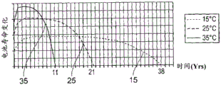
图17是示出电池的可用寿命如何随温度变化的图表;Figure 17 is a graph showing how the useful life of a battery varies with temperature;
图18是实施本发明的一种形式的设备的示意图;Figure 18 is a schematic diagram of an apparatus embodying one form of the present invention;
图19是为图18的设备的一部分的换热器的截面的扩大图;Figure 19 is an enlarged view of a cross-section of a heat exchanger that is part of the apparatus of Figure 18;
图20是实施本发明的第二种形式的设备的示意图;以及Figure 20 is a schematic diagram of an apparatus embodying a second form of the present invention; and
图21是实施本发明的又一种形式的设备的示意图。Figure 21 is a schematic diagram of yet another form of apparatus embodying the present invention.
在下面的描述中,相似附图标记尽可能指示相似部件。In the following description, like reference numerals refer to like parts wherever possible.
具体实施方式Detailed ways
从上文中将理解,本发明的一些实施例的操作依赖于诸如水的某些流体的公知的异常特性中的一个:即,其密度在临界温度(在水的情形中,大约4℃)处最大,如在图1中所示。将水作为示例参考在本文中使用,但是将理解,具有类似特性的其他流体也是有用的。包括水的流体也是有用的,诸如盐水。盐可允许临界温度下降。其他添加物对于使水或其他流体的临界温度下降或上升是有用的。It will be appreciated from the foregoing that the operation of some embodiments of the present invention relies on one of the well-known anomalous properties of certain fluids, such as water: namely, that its density is at a critical temperature (in the case of water, about 4°C) maximum, as shown in Figure 1. Water is used herein as an example reference, but it will be appreciated that other fluids with similar properties are also useful. Fluids including water are also useful, such as saline. Salt allows the critical temperature to drop. Other additives are useful for lowering or raising the critical temperature of water or other fluids.
水的密度随温度变化而在临界温度处具有最大值的事实,是因为如下事实,即,水在低于大约4℃时具有负的热膨胀温度系数,而在高于大约4℃时具有正的热膨胀温度系数。下文中,用语“临界温度”将用于参考流体密度处于其最大值时的温度,在水的情形中,该温度为大约4℃。The fact that the density of water has a maximum at the critical temperature as a function of temperature is due to the fact that water has a negative temperature coefficient of thermal expansion below about 4°C and a positive temperature above about 4°C Thermal expansion temperature coefficient. Hereinafter, the term "critical temperature" will be used to refer to the temperature at which the density of the fluid is at its maximum, which in the case of water is about 4°C.
在共同未决的PCT申请NO. PCT/GB2010/051129中公开的设备中,在有效载荷空间上方设置顶部空间。该布置在功能上是有利的,但是就用于特定应用的包装而言可被损害。更特别地,申请人已经确定,在有效载荷空间上方设置顶部空间可限制可用于在一些布置中使用的零售台面(retail frontage)。也就是说,顶部空间占用了在设备前部、可为最有价值或最有用的制冷存储空间的设备体积的一部分。In the apparatus disclosed in co-pending PCT application NO. PCT/GB2010/051129, a head space is provided above the payload space. This arrangement is functionally advantageous, but can be compromised in terms of packaging for specific applications. More particularly, Applicants have determined that providing headspace above the payload space can limit the retail frontage available for use in some arrangements. That is, the headspace occupies a portion of the volume of the device at the front of the device that could be the most valuable or useful refrigerated storage space.
申请人已经发现,可以将顶部空间,即包含冷却器件的储存器,定位在存储隔室的后方(相对于在其上方),并且依然使用与在先申请的热原理类似的热原理来实现存储隔室的充分冷却。Applicants have discovered that it is possible to position the headspace, ie the reservoir containing the cooling means, behind the storage compartment (as opposed to above it) and still achieve storage using similar thermal principles to those of the earlier application Adequate cooling of the compartment.
首先参考图2,实施本发明的第一形式的制冷设备大体以1示出。Referring first to FIG. 2 , a refrigeration apparatus embodying a first form of the present invention is shown generally at 1 .
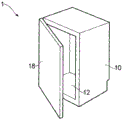
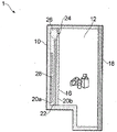
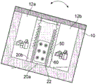
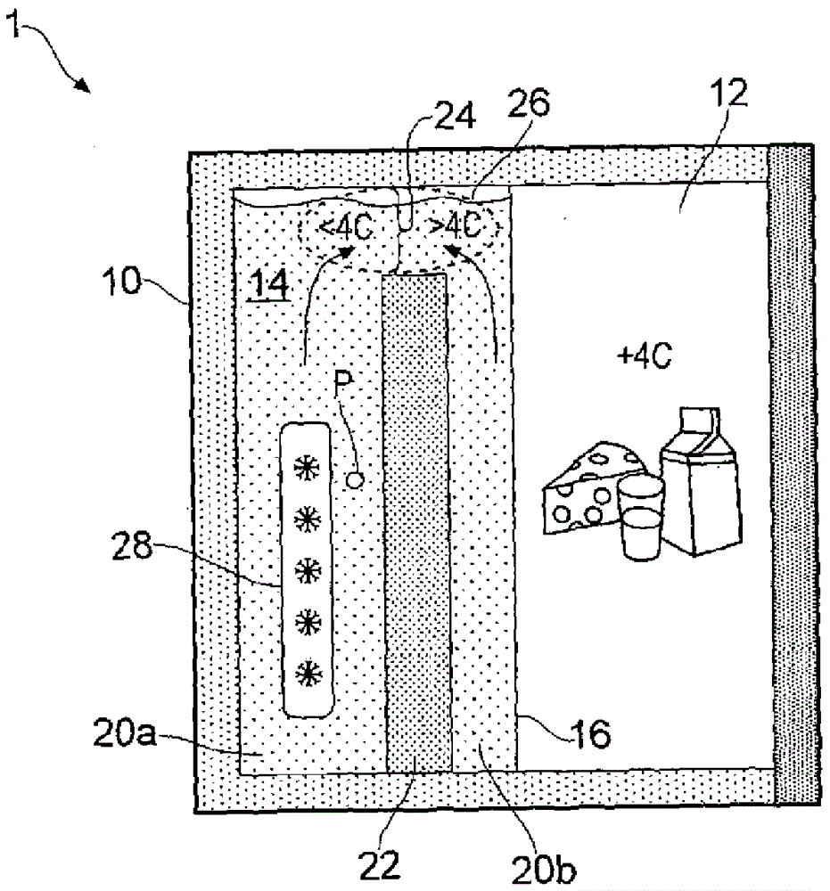
设备1包括外壳10,其在该实施例中,大体成形为直立长方体。外壳10由绝热材料形成,以减小进入或离开设备1的热传递。例如,外壳10可形成为塑料材料的单件旋转模塑体。外壳10内的体积借助于分隔件分成邻近隔室,有效载荷隔室12和流体体积14,该分隔件包括在外壳10的上部、下部以及侧壁之间延伸的导热壁16。The device 1 comprises a
有效载荷隔室12布置成存储待冷却的一个或更多个物体或物品,诸如疫苗、食品或包装饮料。如在图3中所示,有效载荷隔室12可包括诸如门18的闭合件,其可被开启以通过外壳10的开口面接近隔室。门18上携带绝热材料,以使当其闭合时,通过其的热传递减小。在备选实施例(未示出)中,有效载荷隔室12可为开口面(open-face)的,从而容许容易接近存储在其中的物体或物品。例如,有效载荷隔室可包括货架单元,用于在零售出口或商店中使用。The
流体体积14通过堰器件自身部分分成相应的第一和第二流体储存器20a、20b,该堰器件呈从流体体积14的下壁向上延伸以及在其侧壁之间完全延伸的热屏障或壁22的形式。壁22可由具有合适绝热特性的大致任何材料形成。特别地,有利的是,壁22由具有低导热率的材料形成,以便减小在第一和第二流体储存器之间通过其的热传递。在一些备选布置中,间隙可设在壁22和由外壳10限定的流体体积14的侧壁之间。The
在所示实施例中,壁22在距上壁的一距离处终止,使得在其间限定狭槽或开口24。狭槽或开口24由此在相应的第一和第二流体储存器20a、20b的上区域之间提供流体和/或热流动路径。第一和第二流体储存器20a、20b因此在它们的上区域处流体连通,该上区域一起限定流体混合区域,其通过虚线26近似示出,并且在下面描述。In the embodiment shown, the
呈电力驱动的冷却元件28的形式的冷却器件设置在第一流体储存器20a内,以便浸入在流体中。冷却元件28设置在第一流体储存器20a的下区域中,并且通过流体层与储存器的侧壁、端壁、上壁以及下壁间隔。设备具有外部电源(未示出),以将电功率供应至冷却元件28。在没有明亮阳光的情况下,电源可利用干线电源操作。电源还可利用光伏板(未示出)操作,从而设备1可在白天有阳光的条件下无需干线电源运行。Cooling means in the form of electrically driven
在一些实施例中,冷却元件28可布置成借助于泵送通过其的制冷剂来冷却在第一流体储存器20a中的流体,该制冷剂借助于流体体积14外部的泵泵送。在一些实施例中,冷却元件28通过制冷器泵送,冷却元件28已经通过压缩制冷剂的膨胀(以常规的蒸发-压缩制冷循环的方式)而冷却。In some embodiments, the
第一和第二流体储存器20a、20b各自包含一定体积的流体,其具有低于临界温度时负的热膨胀温度系数以及高于临界温度时正的热膨胀温度系数。在所示实施例中,流体是水,其临界温度是大约4℃。水很大程度上填充了流体储存器20a、20b两者,但是每个储存器中可留下小的体积未填充以允许膨胀。如上所述,除了水以外的流体也是有用的。特别地,如下液体是有用的,即,该液体具有临界温度,低于该临界温度时,液体密度随下降的温度而下降(即,当冷却至低于临界温度时,具有负的热膨胀温度系数),并且在高于该临界温度时,液体密度随升高的温度而下降(即,当加热至高于临界温度时,具有正的热膨胀系数)。The first and
现在将描述设备1的操作。The operation of the device 1 will now be described.
可假定在第一和第二流体储存器20a、20b中的所有水最初都处于环境温度或在环境温度附近。启动设备1,使得电功率供应至冷却元件28,其由此冷却至典型地远低于水的冰点的温度,例如,低至-30℃。这进而导致第一流体储存器20a内的冷却元件28的紧邻周边中的水冷却。随着水冷却,其密度增大。冷却的水因此朝第一流体储存器20a的底部下沉,从而使更热的水移位,该更热的水朝第一流体储存器20a的上区域上升。It can be assumed that all of the water in the first and
将理解,随着时间推移,在第一流体储存器20a中包含的大部分或者全部水冷却至4℃或更低的温度。因此水的密度在临界温度下处于其最大值,所以在该温度下的水趋向于在第一流体储存器20a的底部处聚集(pool),从而使更低温度的水朝第一流体储存器20a的上区域移位。这导致在第一流体储存器20a内生成的大体正的温度梯度,其中处于临界温度的水位于第一流体储存器20a的下区域中,并且处于低于临界温度的温度的密度更小、更轻快的水位于邻近开口24的、在第一和第二流体储存器20a、20b之间的接合部处的上区域中。It will be appreciated that over time most or all of the water contained in the
在该接合部(下文中称为流体混合区域26)处,处于低于临界温度的温度的水通过处于临界温度的水在第一流体储存器20a内的下沉而向上移位,其与更热的水相遇并且混合,该更热的水例如处于大约10℃,设置在第二流体储存器20b的上区域中。因此在混合区域26内发生从更热的水到更冷的水的热传递,从而导致来自第一流体储存器20a的冷水和来自第二流体储存器20b的更热的水分别朝临界温度增大和减小温度。流体混合区域26因此限定了设备1的热传递区域,其中,在来自第一和第二流体储存器的流体之间的热传递发生。At this junction (hereinafter referred to as the fluid mixing zone 26), the water at a temperature below the critical temperature is displaced upward by the sinking of the water at the critical temperature within the
随着来自第一流体储存器20a的冷水在温度上朝临界温度上升,其密度增大,如在图1中所示,并且因此其重新向下朝冷却元件28下沉,从而使下方更冷的水移位。类似地,随着来自第二流体储存器20b的更热的水在温度上朝临界温度下降,其密度增大,并且因此其也向下朝第二流体储存器20b的下区域下沉,从而使下方更热的水移位。As the cold water from the
在于混合区域26内混合之后冷却的在第二流体储存器20b中的水在第二流体储存器20b的底部处聚集,其如上所述设置成与有效载荷隔室12热连通。来自有效载荷隔室12的热因此被第二流体储存器20b中的冷却体积的水吸收,并且有效载荷隔室12的温度,以及因此存储在其中的物体或物品的温度开始下降。The water in the
为了重复,通过冷却元件28冷却至低于临界温度的温度的第一流体储存器20a内的水通过处于临界温度的水向上朝混合区域26移位。相反地,在第二流体储存器20b内,高于临界温度的水通过处于临界温度的水朝混合区域26向上移位。因此,在热屏障22任一侧的水,以及处于在临界温度任一侧的温度的水在混合区域26内合并并且混合,从而导致在混合区域26中的水的平均温度接近临界温度,并且因此重新倾泻或下沉到相应流体储存器20a、20b的下区域中。To repeat, the water in the
随着时间推移,通过在上升至第一流体储存器20a的上区域的处于低于临界温度的温度的水与上升至第二流体储存器20b的上区域的处于高于临界温度的温度的水之间的动态热传递,该过程达到接近稳定状态的状态。在一些实施例中,在稳定状态下,在第一和可选的额外第二储存器中的流体为大致静态的,输热主要经由传导发生。Over time, through water at a temperature below the critical temperature rising to the upper region of the
申请人已经发现了出乎意料的技术效果,即,随着时间推移,虽然冷却元件28设置在第一流体储存器20a的下区域中,但是在第二流体储存器20b中的水的温度达到大约处于临界温度的稳定状态温度。也就是说,在第二流体储存器20b中的大部分或全部水,尤其是在其下区域处,变得相对停滞,其中温度为大约4℃。通过从有效载荷隔室12吸热而加热至高于临界温度的水通过已通过在第一流体储存器20a的上区域中的低于临界温度的水冷却的、从混合区域26下降的处于临界温度的水而朝混合区域26移位。Applicants have discovered the unexpected technical effect that over time, although the
通过由在第二流体储存器20b中的水从有效载荷隔室12吸热,有效载荷隔室12维持在大约4℃的期望温度处,该期望温度对于存储许多产品,包括疫苗、食品和饮料而言是理想的。By absorbing heat from the
将理解,与冷却元件28接触的流体将典型地冰冻,并且冰冻流体的固态质量体或冰将在第一流体储存器中形成。可提供冰检测器,用于在一旦冰已经生长至临界大小时检测冰的形成。一旦检测器检测到临界大小的冰的形成,设备可布置成切断冷却元件28,以防止进一步的冰形成。一旦冰冻流体的质量体已经随后收缩至低于临界大小的大小,则冷却元件可重新启动。检测器可呈热探头P的形式,其与距冷却元件28的给定距离处的流体热接触。一旦冰冻流体开始与探头P接触,则与探头热接触的流体将下降至处于或接近冰冻流体的温度的温度。将理解,相对突然的温度变化典型地在冰冻的冰的质量体和在距冰冻质量体的非常短的距离内与冰接触的流体之间发生。It will be appreciated that the fluid in contact with the
在至冷却元件28的电源被中断或断开的情况下,在第一和第二流体储存器20a、20b内的水上所施加的移位过程继续,而冰冻流体的质量体保持在第一流体储存器20a中。一旦冰冻流体的质量体耗尽,移位过程将开始缓慢,但是通过由在第二流体储存器20b中的水从有效载荷空间12持续吸热而维持。由于水的高比热容以及流体体积内处于低于临界温度的温度的水的显著体积,故在第二流体储存器20b的下区域中的温度在相当长的时间内保持在4℃或接近4℃。In the event that the power supply to the
也就是说,即使在没有电功率供应至冷却元件28的情况下,处于临界温度的水下沉的自然趋势以及使高于或低于临界温度的水移位导致第一和第二流体储存器20a、20b,或至少其下区域,在失去功率后,将水保持在临界温度处或其附近一段时间,从而使得有效载荷隔室12能够维持在可接受的温度范围内达延长的时间段。本发明的实施例能够在失去功率后将第二储存器20b中的流体维持在目标温度处达高达若干周的时段。That is, even in the absence of electrical power being supplied to the
图4和图5示出了图2的实施例的变型,其适于对现有制冷装置改造。在图4的实施例中,外壳10的外部形状构造成与常规制冷器的内部体积互补并且位于该内部体积内。特别地,外壳10的背面的下区域向内呈阶梯状,以容纳用于制冷器的冷凝器和马达的壳体,该壳体通常设置在制冷器的下后部处。Figures 4 and 5 show a variant of the embodiment of Figure 2, which is suitable for retrofitting existing refrigeration installations. In the embodiment of Figure 4, the outer shape of the
在图5的实施例中,除了外壳10的修改的外部形状外,冷却元件28设置在第一流体储存器20a外侧,并且替代地集成到外壳10的后壁中,并且与包含在第一流体储存器20a中的水热连通。In the embodiment of FIG. 5 , in addition to the modified outer shape of the
图4和图5的实施例的操作与图2的实施例的操作大致相同。还将认识到,冷却元件28在第一流体储存器20a外侧的定位可独立于外壳10的外部形状实施,例如在图2的实施例中。The operation of the embodiment of FIGS. 4 and 5 is substantially the same as that of the embodiment of FIG. 2 . It will also be appreciated that the positioning of the
在图4和图5的实施例的又一变型(未示出)中,冷却元件28被消除,并且外壳10的后壁由导热部分替换,该导热部分诸如隔膜或其他导热板、元件、部件或结构。在该布置中,冷却器件包括自身既有的制冷装置,制冷装置的冷却元件用于执行冷却元件28的功能。此类实施例的操作与图2的实施例在第一流体储存器20a中的水被冷却方面大致相同,在该情形中,冷却通过与其热连通的制冷装置的冷却设备,通过传导隔膜,从而建立以上描述的热引发的流体移位过程。In yet another variation (not shown) of the embodiment of Figures 4 and 5, the
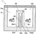
接下来参考图6和图7的实施例,示出了双有效载荷空间布置。在该实施例中,填充流体的冷却腔室50设置在外壳10内,其中有效载荷隔室12a、12b限定在其每一侧。冷却腔室通过堰器件至少部分地分成三个腔室,其分别限定中央流体储存器20a以及两个外流体储存器20b1、20b2,该堰器件呈两个直立、大体平行壁22a、22b的形式。在所示实施例中,壁22a、22b不完全延伸至冷却腔室50的上壁,并且因此限定横跨相应流体储存器20a、20b1、20b2的上区域设置的流体混合区域26。Referring next to the embodiments of Figures 6 and 7, a dual payload space arrangement is shown. In this embodiment, a fluid-filled
在该实施例中,中央流体储存器20a包含呈电驱动的冷却元件28的形式的冷却器件,并且因此在功能上与图2的实施例的第一流体储存器20a等同。类似地,外流体储存器20b1、20b2中的每一个与相应有效载荷隔室12a、12b热连通,并且因此在功能上与图2的实施例的第二流体储存器20b等同。In this embodiment, the
图6的实施例的操作类似于图2的实施例的操作。具体地,中央流体储存室20a内冷却至低于临界温度的水通过处于临界温度的下沉至储存器的底部的水朝流体混合区域26移位。在流体混合区域26中,低于临界温度的水与来自外流体储存器20b1、20b2的更热的水混合,该更热的水由此在热传递过程中朝临界温度冷却,并且因此向下下沉到外流体储存器中,使更热的水向上移位到流体混合区域26中。来自中央流体储存器20a的低于临界温度的水通过该热传递过程朝临界温度加热,并且由于密度的相应增大,下沉到中央流体储存器20a中,由此使更冷的水向上移位到流体混合区域26中,基于此,该过程重复。将理解,在一些实施例中,在一个流体储存器内上升的流体可随后在不同的流体储存器内下降。The operation of the embodiment of FIG. 6 is similar to the operation of the embodiment of FIG. 2 . Specifically, water cooled below the critical temperature within the central
该过程继续,直到在外流体储存器20b1、20b2中的水到达处于4℃或在4℃附近的大致稳定状态,并且通过在储存器内持续的热引发的水移位以及随后在流体混合区域26内的混合而维持在该温度处或在该温度附近。This process continues until the water in the outer fluid reservoirs 20b1 , 20b2 reaches a substantially steady state at or near 4°C, and through continued thermally induced water displacement within the reservoir and subsequent
图7的实施例在结构上类似于图6的实施例。然而在该实施例中,冷却元件28由冷却材料的主体52替换,冷却材料的主体52处于低于有效载荷隔室的预期操作温度的温度。其典型地将低于0℃。-18℃附近的温度可通过将主体52在使用前置放在常规食物冰冻器中而获得,并且-30℃或更小的温度将模仿制冷单元的效应。冷却材料的主体52可为具有合适热质量体的任意物。然而,冰水混合物尤其合适,因为其能够容易获得,并且具有有利地高的融解潜热。The embodiment of FIG. 7 is similar in structure to the embodiment of FIG. 6 . In this embodiment, however, the
冰可呈标准的0.6升、涂覆塑料的冰袋形式,其在医疗用品的运输和存储中使用。其他大小的冰袋也是有用的。可使用其他布置。在一个实施例中,一个或更多个块冰,或者方块冰的质量体引入到中央流体储存器20a中。在该情形中,由于冰的移位体积比当融化时的等同物体积更大,所以随着冰融化,在储存器中的水的总体体积减小。在冷却腔室50内应当维持在热屏障22a、22b上方的足够的吃水深度,以实现当冰的体积在融化期间减小时的流体混合。在一些布置中,可另外或替代地提供液体排放布置。The ice can be in the form of a standard 0.6 liter, plastic-coated ice pack, which is used in the transportation and storage of medical supplies. Other sized ice packs are also useful. Other arrangements can be used. In one embodiment, one or more ice cubes, or masses of ice cubes, are introduced into the
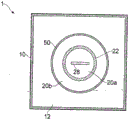
图8以平面视图示出了本发明的又一实施例。在该实施例中,圆筒形填充流体的冷却腔室50大体居中地设置在外壳10内,其中有效载荷隔室12由冷却腔室50外的空间限定。腔室50的其他位置也是有用的。Figure 8 shows a further embodiment of the invention in plan view. In this embodiment, the cylindrical fluid-filled
冷却腔室50通过堰器件分成内和外流体储存器20a、20b,该堰器件呈从冷却腔室的下表面向上延伸的大体直立、圆筒形或管形壁22的形式。由壁22定界的圆柱形体积包括内流体储存器20a,而壁22外侧的环状体积包括外流体储存器20b。在所示实施例中,壁22不完全延伸至冷却腔室50的上壁,并且因此限定横跨相应流体储存器20a、20b的上区域设置的流体混合区域(未示出)。The cooling
在该实施例中,内流体储存器20a包含呈电驱动的冷却元件28的形式的冷却器件,并且因此在功能上与图2的实施例的第一流体储存器20a等同。类似地,外流体储存器20b与有效载荷隔室12热连通,并且因此在功能上与图2的实施例的第二流体储存器20b等同。In this embodiment, the
图8的实施例的操作类似于图2的实施例的操作。具体地,内流体储存器20a内冷却至低于临界温度的水通过处于临界温度的下沉至储存器的底部的水朝流体混合区域26移位。在流体混合区域26中,低于临界温度的水与来自外流体储存器20b的更热的水混合,该更热的水由此在热传递过程中朝临界温度冷却,并且因此向下下沉到外流体储存器20b中,使更热的水向上移位到流体混合区域26中。来自内流体储存器20a的低于临界温度的水通过该热传递过程朝临界温度加热,并且由于密度的对应增大,下沉到中央流体储存器20a中,由此使更冷的水向上移位到流体混合区域26中,基于此,该过程重复。The operation of the embodiment of FIG. 8 is similar to that of the embodiment of FIG. 2 . Specifically, water cooled below the critical temperature within the
该过程继续,直到在外流体储存器20b中的水到达处于4℃或在4℃附近的大致稳定状态,并且通过在流体储存器内持续的热引发的水移位以及随后在流体混合区域26内的混合而维持在该温度处或在该温度附近。This process continues until the water in the
将认识到,图6-8的实施例可在诸如可见于超市中的零售货架中找到有利的应用。通过将冷却腔室50设置在相对的可接近的有效载荷隔室12a、12b之间,或者在外壳内居中地设置,使得提供360°有效载荷隔室12,设备1可定位在超市内的邻近过道之间,或作为居中定位的独立单元,提供增加的零售台面和用于产品置放的改进的灵活性。It will be appreciated that the embodiments of Figures 6-8 may find advantageous application in retail shelves such as may be found in supermarkets. By locating the cooling
接着参考图9a和图9b,示出了图8的实施例的变型。在该实施例中,冷却腔室50在外壳10的上壁和下壁之间完全延伸(虽然这不是必要的),并且热屏障22由圆筒或套筒60围绕,圆筒或套筒60由具有低热导率的材料形成。圆筒60的长度可变化,使得在其最小长度下,其大约延伸至环状壁22的端部,由此保留在内与外流体储存器20a、20b之间的热流动路径,而在其最大长度下,其延伸成与冷却腔室50或外壳10的上壁邻接。在该长度延伸的构型中,外流体储存器20b与内流体储存器20a流体隔离且隔热(或热隔离)。Referring next to Figures 9a and 9b, a variation of the embodiment of Figure 8 is shown. In this embodiment, the cooling
在一个实施例中,设想的是,套筒可采取波纹管布置60的形式,其自然长度相当于壁22的高度,但是其可拉伸或膨胀,使得其可闭合和/或密封掉内流体储存器20a。波纹管60可包括双金属结构,其以如下方式构造,即,当冷却时,波纹管朝闭合位置膨胀。In one embodiment, it is envisaged that the sleeve may take the form of a
此类布置可对于其中要求制冷设备移动或频繁或有规律地重定位的移动应用而言是有益的。设备以及因此流体体积的移动趋于搅动水,从而扰乱正常的热引发的流体移位过程。Such an arrangement may be beneficial for mobile applications where the refrigeration equipment is required to be moved or relocated frequently or regularly. Movement of the device and therefore the fluid volume tends to agitate the water, disrupting the normal thermally induced fluid displacement process.
然而,在当前实施例中,当通过设备的移动搅动时,在中央流体储存器20a中的更冷的水可被导致溢出到外流体储存器20a中,从而降低其中的温度。该温度的下降“启动”波纹管布置60来闭合狭槽或孔口24,并且因此大致隔离中央流体储存器20a,如在图9b中所示。However, in the current embodiment, the cooler water in the
一旦设备重定位并且在外流体储存器20b中的水的温度上升,则波纹管布置60收缩至其自然长度,以容许重新建立期望的流体移位过程。Once the device is repositioned and the temperature of the water in the
波纹管布置60的内表面可隔热以防止通过其的显著热传导。The inner surface of the
从上文将认识到,波纹管布置作为一种形式的阀起作用,其可选择性地闭合以便中断设备内部的导热过程,并且在重新建立该过程时开启。还设想,此类阀器件的设置可使得外流体储存器20b中的流体的温度能够改变。特别地,通过减小在壁22的端部与冷却腔室50的上壁之间的间隙24的深度,诸如通过使波纹管布置60部分延伸,在中央流体储存器20a中的水与外流体储存器20b中的水之间的导热可被选择性地调节,例如减小。这容许外流体储存器20b中的水的温度升高至高于临界温度(取决于包含在有效载荷隔室12中的物体或物品的性质),这可为有益的。It will be appreciated from the above that the bellows arrangement functions as a form of valve that can be selectively closed to interrupt the thermal conduction process inside the device and opened when the process is re-established. It is also envisaged that the provision of such valve means may enable the temperature of the fluid in the
设想的是,取决于应用,波纹管布置60可构造成在任何期望温度下操作,也就是说,开启和/或闭合。例如,在电池冷却器中,波纹管60可布置成在大约25℃的温度处闭合,并且布置成在外流体储存器20b中的水的温度超过该水平时释放更冷的水。It is contemplated that, depending on the application, the
在一些实施例中,除了波纹管布置外的阀器件可为有用的,例如,具有可调节开口的狭槽、可移动遮板、门阀、球阀、蝴蝶阀或任何其他合适的阀。In some embodiments, valve means other than bellows arrangements may be useful, eg, slots with adjustable openings, movable shutters, gate valves, ball valves, butterfly valves, or any other suitable valve.
在另一实施例(未示出)中,波纹管布置60或其他阀类型通过外壳10的上壁连接于附连于其的可收缩手提把手。手提把手能够在收缩位置与展开的使用位置之间移动,后者使得设备能够被用户提着。波纹管布置60或其他阀器件以如下方式连接于把手,即,在把手的展开位置,波纹管延伸成与上壁邻接,从而使中央储存器20a对外流体储存器20b大致密封掉。在其他阀器件的情形中,提升把手器件可导致阀器件的闭合,例如通过向上提升门阀的阀部分(或使其向下移动)来将储存器20a与储存器20b隔离。此类布置确保,在设备1要求把手展开的移动期间,储存器相互隔离,以便在运输期间限制流体的混合,以及因此的热中断。一旦重新定位设备,则把手下降或收缩,从而导致波纹管布置60收缩至其自然开启位置,或其他阀器件开启。In another embodiment (not shown), a
设想的是,把手还可连接于设备的门或闭合件,使得展开把手不仅提升波纹管或闭合其他阀器件以及大致密封掉流体储存器,而且额外地锁定了闭合件。在设备的重定位之后释放把手降低了波纹管布置60或开启了其他阀器件,并且解锁闭合件。It is envisaged that the handle may also be connected to the door or closure of the device such that deploying the handle not only lifts the bellows or closes other valve means and substantially seals off the fluid reservoir, but additionally locks the closure. Releasing the handle after repositioning of the device lowers the
将认识到,上述波纹管布置60不限于图9a和9b的实施例,而是可容易地适于或重构造用于在图2-8的实施例中使用。It will be appreciated that the above-described
还将理解,如上文所述,以上描述的可收缩把手可连接于不包括波纹管布置的阀。在把手在收缩位置的情况下,阀可布置成开启;在把手在展开状态(诸如当提着设备时)的情况下,阀可布置成闭合。It will also be appreciated that the retractable handle described above can be connected to a valve that does not include a bellows arrangement, as described above. With the handle in the retracted position, the valve may be arranged to open; with the handle in the deployed state, such as when the device is being lifted, the valve may be arranged to close.
以上描述假定水的最大密度在4℃处出现,对纯水而言是这种情况。通过将杂质引入到水中,最大密度出现时的温度可被改变。例如,如果将盐添加至水达3.5%的浓度(大约是海水的浓度),则最大密度在2℃附近处出现。这可用于针对具体应用调节有效载荷空间的温度。根据需要,可采用其他添加剂来升高或降低临界温度。The above description assumes that the maximum density of water occurs at 4°C, which is the case for pure water. By introducing impurities into the water, the temperature at which the maximum density occurs can be changed. For example, if salt is added to water to a concentration of 3.5% (approximately the concentration of seawater), the maximum density occurs around 2°C. This can be used to adjust the temperature of the payload space for specific applications. Other additives can be used to raise or lower the critical temperature as needed.
图10示出了其中壁22在流体体积14内的位置为可调节的又一实施例。正如上述波纹管布置60那样,调节壁22的位置允许流体移位过程被修改,例如减慢或减小。在所示实施例中,壁22能够围绕其下端枢转,以便改变第一和第二流体储存器20a、20b的上开口的面积。这可用于影响在第一和第二流体储存器之间的流体流,并且因此控制在其间的热传递。例如,通过使壁22朝有效载荷隔室12倾斜,第二流体储存器20b的上开口的面积减小,从而减小流体从其移位的速率。这继而允许在第二流体储存器20b中的流体的温度维持在高于4℃的温度处,如果需要的话。从上文将认识到,在该实施例中可移动壁22还充当阀器件。因此,可认为可移动壁22充当阀。FIG. 10 shows yet another embodiment in which the position of the
壁22朝有效载荷隔室12倾斜所提供的另一有益效果是可便于第一流体储存器20a内的冰形成而不阻碍冷却水的向上流进入混合区域26。该有益效果同样可应用于如下情形,其中壁22大致永久地以朝有效载荷隔室倾侧或倾斜的角度固定,在该应用内还设想布置。Another benefit provided by the slope of the
将认识到,本发明的一些实施例提供用于储存和冷却诸如疫苗、易腐烂食品以及多个饮料容器(诸如瓶或饮料罐)的物品的新颖且创造性的装置,提供温度控制存储器件,其可在装置失去功率后维持在合乎需要温度范围内达许多小时。本发明的实施例布置成被动地调整装置内的热能流,以实现温度敏感产品的长期存储。It will be appreciated that some embodiments of the present invention provide novel and inventive apparatus for storing and cooling items such as vaccines, perishable foods, and a plurality of beverage containers such as bottles or beverage cans, providing temperature controlled storage devices that The desired temperature range can be maintained for many hours after the device loses power. Embodiments of the present invention are arranged to passively adjust the flow of thermal energy within the device to enable long term storage of temperature sensitive products.
具有特别益处的特征为,在本发明的实施例中,流体储存器20a、20b与有效载荷隔室12成并排构型设置。通过避免使用在有效载荷隔室上方的顶部空间,提供更大的通用性,用于设定有效载荷隔室的尺寸、形状和位置。A feature of particular benefit is that, in embodiments of the present invention, the
本发明的其他实施例提供用于冷却物品的冷却器,诸如用于冷却用作备用电源的电池的电池冷却器。在该情形中,电池可容纳在有效载荷隔室12中或在与第二或外流体储存器20b、20b1、20b2(图6)热连通的其他区域中。在实施例中,在第二隔室20b中的流体可提供成经由一个或更多个流体导管与用于冷却电池的换热器流体连通。Other embodiments of the invention provide coolers for cooling items, such as battery coolers for cooling batteries used as backup power sources. In this case, the battery may be housed in the
因此,第二流体储存器20b可充当用于冷却结构、装置或构件的冷却剂源。在一些实施例中,换热器可穿过第二流体储存器,例如以流体导管的形式,导管允许在流过导管的流体(诸如液体或气体)与第二流体储存器20b中的液体之间的换热。流过导管的流体可例如为饮料、诸如液体燃料的燃料、气态燃料或任何其他合适的液体。Thus, the
本发明的实施例可实现相对缓慢和/或温和的热传递过程,这主要由通过流体的导热实现,但是在系统启动时,这可更迅速地实现,以便导致第二或外流体储存器20b、20b1、20b2借助于流体体积内热引发的流体移位更快速地达到工作温度。Embodiments of the present invention may achieve a relatively slow and/or gentle heat transfer process, which is primarily achieved by heat conduction through the fluid, but may be achieved more rapidly at system start-up so as to result in a second or
图11是又一实施例的截面示意图,其中壁22定位在流体体积14内,使得在壁22的下边缘和外壳10的基部之间提供间隙或裂缝。间隙30允许液体从第一流体储存器20a传递至第二流体储存器20b,并且反之亦然。FIG. 11 is a schematic cross-sectional view of yet another embodiment in which the
在一些备选实施例中,一个或更多个裂缝或孔口可设在壁22的下区域中,以允许流体通过其从壁22的一侧到另一侧的流。在一些备选方案中,基部壁可提供成上升距外壳10的基部的相对短距离,间隙30设在基部壁的上边缘和壁22之间。In some alternative embodiments, one or more slits or orifices may be provided in the lower region of the
在使用中,间隙30的存在便于在第二流体储存器20b中的液体以及因此有效载荷隔室12的更迅速的初始冷却。这是因为,在初始冷却时,已被冷却元件28冷却的流体可在其朝其临界温度冷却时初始地下沉。一旦在第一流体储存器20a的下区域中,则流体可实现在第二储存器20b中的流体的冷却。通过在第一储存器20a内下降的流体的第二储存器中的流体的冷却可通过导热发生。此外,冷却可通过冷却流体从第一流体储存器20a通过间隙30传递至第二流体储存器20b而实现。In use, the presence of the
将理解,最终,可实现平衡状态,其中在第一储存器20a中通过低于临界温度的冷却元件28冷却的流体通过处于临界温度的流体的下沉而向上移位,并且(在一些实施例中)与更热的流体(例如处于大约10℃,设置在第二流体储存器20b的上区域中)相遇和混合。因此从更热的流体到更冷的流体的热传递在混合区域26内发生,从而导致来自第一流体储存器20a的更冷的流体和来自第二流体储存器20b的更热的流体分别朝临界温度增大和减小温度。流体混合区域26因此限定了设备1的热传递区域,其中,在来自第一和第二流体储存器20a、20b的流体之间的热传递发生。将理解,在不容许第一和第二储存器20a、20b中的流体在区域26中混合的情况下,区域26限定不是流体混合区域的热传递区域。It will be appreciated that, ultimately, an equilibrium state may be achieved wherein the fluid cooled by the
如本文中描述的,冷却元件28可呈冰水混合体的形式,例如冰袋或零散的冰,其保持浸没在第一流体储存器20a内,可选地在其下区域中,例如在第一流体储存器20a的整个深度的三分之一或更多的深度处。冷却元件可包括电冷却元件,其能够操作成冷却第一流体储存器20a中的液体。冷却元件可能够操作成冰冻第一流体储存器20a中的流体,以形成冰冻主体。与冰冻主体热连通的流体可冷却,从而低于临界温度。As described herein, the
在一些实施例中,设备1可能够操作成开启和闭合间隙30。例如,在设备1的初始启动后,当第一和第二流体储存器20a、20b中的流体已经充分冷却时,间隙30可闭合。In some embodiments, the apparatus 1 may be operable to open and close the
在间隙30如上所述设在壁22和外壳10的基部表面或基部壁之间的情形中,间隙30可通过壁22向下的移动来闭合。在一个或更多个裂缝或孔口设在壁22中的情形中,裂缝或孔口可借助于遮板布置开启和闭合。其他布置也是有用的。Where
在一些实施例中,在冷却元件28或其他冷却器件失去功率后,例如由于冰袋中冰的融化,可建立(开启)间隙30以便延长有用的冷却。因此,在第一储存器20a的下区域中处于临界温度的流体可从第二流体储存器20b中的更热的流体接受热能,从而冷却第二储存器20b中的流体。其他布置也是有用的。In some embodiments, after cooling
图12示出了根据本发明的实施例的设备50,其呈填充液体的内衬50的形式。内衬50布置成设在隔热容器内,并且布置成冷却容器内的一个或更多个物体。Figure 12 shows a
图12中示出的内衬50在平面视图中为大致C形。其包括第一部分52,其具有由壁22(未示出)以与图2的布置类似的方式分离的第一和第二流体储存器20a、20b(未示出)。第二流体储存器20b与两个填充流体的颊部分54、56热连通(并且在一些实施例还为流体连通),两个填充流体的颊部分54、56从第一部分52的相对端侧向突出。在图12的实施例中,第一部分52与颊部分54、56的高度大致相同,但是其他布置也是有用的。The
在使用中,内衬50填充有流体,使得第一和第二流体存储器20a、20b以及颊部分54、56填充至充分高的水平。在第一储存器20a中的流体接着通过冷却元件28冷却,冷却元件28可例如呈电冷却元件28或如上所述的冰冻液体主体的形式。冷却元件28将第一流体存储器20a中的液体冷却至低于临界温度。如在以上描述的实施例的情形中,在第一储存器20a中通过低于临界温度的冷却元件28冷却的流体通过处于临界温度的流体的下沉而向上移位,并且与更热的流体(例如处于大约10℃,设置在第二流体储存器20b的上区域中)相遇和混合。从更热的流体到更冷的流体的热传递因此在混合区域26内(图2)发生,从而导致来自第一流体储存器20a的更冷的流体和来自第二流体储存器20b的更热的流体分别朝临界温度增大或减小温度。由于内衬50的第一部分52中的第二流体储存器中的流体与颊部分54、56中的流体热连通,故颊部分中的流体的冷却发生。In use, the
其中除了第一部分外还提供颊部分54、56的图12的实施例具有如下优势,即,相比于不具有颊部分的设备,诸如图2的设备1,可提供具有更大表面面积的设备50。The embodiment of Fig. 12 in which
此外,以内衬50的形式提供设备50允许通过将内衬50插入到设备中而将任何合适的绝热容器转化成制冷设备的可能性。因此,通过将诸如图12的内衬50的内衬引入到设备中,本发明的实施例容许将常规制冷器转化成根据本发明的实施例的制冷设备。Furthermore, providing the
将理解,根据本发明的实施例的内衬50可提供成仅具有一个颊部分54、56。可提供内衬50,其中一个或更多个颊部分54、56具有与图12的实施例的颊部分54、56不同的形状和/或大小。在一些实施例中,提供一种设备,其适于引入到绝热容器中,设备类似于图12的设备,但是不具有一个或更多个颊部分54、56。设备可称为“改造”设备,其适于引入到诸如常规制冷器的绝热容器中。在一些实施例中,常规制冷器的冷却元件可用作第一流体储存器20a的冷却元件28。备选地,在一些实施例中,常规制冷器的冷却元件可用于冷却第一流体储存器20a的冷却元件28。其他布置也是有用的。It will be appreciated that the
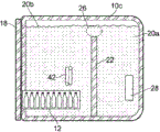
图13是根据本发明的实施例的设备1的正视图,其中设备的外壳的前部被移除,而图14是设备的侧视图,其中设备的外壳的侧部被移除。设备以与图2的设备类似的方式起作用。如在图中的每一个的情形中,相应实施例的相似特征设有相似的附图标记。Figure 13 is a front view of the device 1 according to an embodiment of the invention with the front of the housing of the device removed, and Figure 14 is a side view of the device with the sides of the housing of the device removed. The device functions in a similar manner to the device of FIG. 2 . As in the case of each of the figures, like features of the corresponding embodiment are provided with like reference numerals.
图13和图14的设备1与以上描述的不同之处在于,有效载荷体积12更小,并且浸入在第二流体储存器20b中的流体内。此外,提供接受器42,其也浸入在第二流体储存器20b中的流体中,用于存储的物品可置放到接受器42中。The device 1 of Figures 13 and 14 differs from that described above in that the
多个孔口40设在外壳10的侧壁10a、10b中的每一个中,每一个都限定进入相应接受器42的开口。在所示实施例中,接受器用于保持饮料容器,诸如瓶或碳酸饮料罐44。在所示实施例中,提供20个接受器42,每个侧壁10a、10b包括十个孔口40(两个水平排,每排五个)。接受器大约设置在外壳10内的中间高度处,在有效载荷容器12和容器10的上壁10c之间。A plurality of
每个接受器42包括向内指向的、端部闭合的管、滤袋(sock)或囊46,其在所述实施例中由诸如橡胶的柔性或弹性体材料形成,并且采取圆锥体的形式,在其闭合端处比在邻近开口40的端部处更窄。Each
每个囊46定尺寸成使得在其中插入饮料容器44导致弹性体材料围绕容器的主体拉伸。这容许容器44被囊46牢固地抓住,从而防止其在使用或运输期间掉落。此外,囊46与容器44物理接触的表面面积增加,从而改进或优化在第二储存器20b中的流体与容器44之间的热传递。Each
为了防止第二储存器20b中的流体的压力导致囊46通过开口40塌陷或下垂,相对的囊46在它们的闭合端处附连于彼此。在备选实施例(未示出)中,每个囊46的闭合端附连或订于容器10的相对壁的内表面。其他布置也是有用的。To prevent the pressure of the fluid in the
不使用所示的渐缩囊,而是可采用任何其他合适的形状,包括非渐缩管形囊。在一些实施例中,管可由硬材料形成,具有带充分低的热阻的壁,以允许置放在其中的物品的有效冷却。在一些实施例中,设备可布置成允许物品在一端处插入到管中,并且从另一端分配。其他布置也是有用的。Instead of the tapered balloons shown, any other suitable shape may be used, including non-reduced tubular balloons. In some embodiments, the tube may be formed of a hard material with walls with sufficiently low thermal resistance to allow for efficient cooling of items placed therein. In some embodiments, the device may be arranged to allow articles to be inserted into the tube at one end and dispensed from the other end. Other arrangements are also useful.
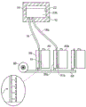
图15是根据本发明的又一实施例的设备1的正视图,其中设备的外壳10的前部被移除,并且图16是设备1的侧视图,其中外壳10的侧部被移除。设备类似于图13和14的设备,除了囊46由换热器件替换,该换热器件呈设置在第二储存器20b内的管42的形式。管42在形成在外壳10的侧壁10、10b中的第一和第二孔口40a、40b之间延伸。孔口40a中的一个限定用于流入换热管42中的流体的入口,而另一孔口40b限定用于流体的出口。Figure 15 is a front view of the device 1 with the front of the
在所示实施例中,管42的主要部分形状为螺旋形,具有一定数量的圈,以便最大化浸入在第二储存器20b中的管的长度,而没有显著增加包装体积,增加包装体积可减小用于有效载荷容器12的可用空间。In the embodiment shown, the main portion of the
限定换热管42的每一端的孔口40可在外壳的相同侧10a中形成,如在附图中所示,或可在相邻或相对侧中形成。多个换热器可取决于可用空间设在设备1中。换热管42大约设置在外壳10内的中间高度处,在有效载荷容器12和外壳10的上壁10c之间。The
换热器的管42可由任何合适材料形成。然而,具有高导热率的材料优选优化在穿过管42的流体与在第二储存器20b内的流体之间的热传递。在一个实施例中,例如,管42由金属材料,诸如铜、不锈钢或任何其他合适材料形成。The
在使用中,待冷却的流体,诸如水或碳酸或非充气饮料,可从存储容器(诸如瓶或桶)通过入口40a借助于压缩器或流体泵或通过重力供应递送到换热管42中。来自管42中的流体的热借助于通过管42的壁的导热传递到周围包含在设备1的第二储存器20b中的冷水中,使得其温度降低。冷却流体接着通过出口40b排出,用于递送至合适的饮料分配设备。In use, a fluid to be cooled, such as water or carbonated or still beverages, may be delivered into the
离开出口40b的流体的温度因此取决于围绕管42的水的温度、管42的长度以及流体在入口40a与出口40b之间的通过时间。在一些实施例中,管42在第二流体储存器20b内的位置可被设定,以便对于通过管42的液体的给定流动速率,提供分配液体的期望温度。The temperature of the
本发明的实施例还适于提供诸如空气的冷却(或冷冻)气体流。冷却气体可用于冷却环境,诸如建筑物、物品或用于任何其他合适的冷却应用。Embodiments of the present invention are also suitable for providing a cooling (or freezing) gas flow such as air. The cooling gas can be used to cool environments, such as buildings, objects, or for any other suitable cooling application.
图17示出了电池寿命(横坐标)对于电池温度随时间的变化。根据Arrhenius方程,电池寿命随着温度增加大体上指数下降,并且一般的经验公式是,电池温度每增加10℃,电池寿命降低50%。Figure 17 shows battery life (abscissa) versus battery temperature over time. According to the Arrhenius equation, battery life generally decreases exponentially with increasing temperature, and a general empirical formula is that for every 10°C increase in battery temperature, battery life decreases by 50%.
因此可从图17中看出,在35℃的温度下操作的电池寿命(线35)为在25℃的温度下操作的电池寿命(线25)的大约一半,并且为在15℃的温度下操作的电池寿命(线15)的大约25%。It can thus be seen from Figure 17 that the battery life operating at a temperature of 35°C (line 35 ) is approximately half the battery life (line 25 ) operating at a temperature of 25°C, and that at a temperature of 15°C About 25% of the battery life of operation (line 15).
将理解,电池操作温度取决于环境温度和从电池的电流消耗两者,该电流消耗也具有对电池的加热效应,并且因此在15℃的环境温度中的操作电池的温度可类似于或甚至高于在35℃的环境温度中的静止电池的温度。因此,电池在高环境温度中操作延长的时段可使电池的寿命降低超过75%,从而需要经常的替换。然而,替换电池的成本和物流在不发达国家或地理上遥远的地区可为令人望而却步的。It will be understood that the battery operating temperature depends on both the ambient temperature and the current draw from the battery, which also has a heating effect on the battery, and thus the temperature of the operating battery in an ambient temperature of 15°C may be similar or even higher The temperature of the stationary cell at an ambient temperature of 35°C. Thus, operating the battery for extended periods of time in high ambient temperatures can reduce the life of the battery by more than 75%, requiring frequent replacement. However, the cost and logistics of replacing batteries can be prohibitive in underdeveloped or geographically distant regions.
接下来参考图18,实施本发明的一种形式的设备大体以100以示意形式示出。设备100预期用于冷却一个或更多个电池,但是设备100还适于冷却其他物品。在所示实施例中,设备100布置成冷却单个电池40。本文中,用语“电池”用于包括单个电池或电池单元,或一起形成电池的多个电池单元。本发明的实施例可用于冷却多个电池单元中的每一个,或包括此类多个电池单元的单个电池。Referring next to FIG. 18, an apparatus embodying one form of the present invention is shown generally at 100 in schematic form.
设备100包括冷却单元1,其类似于图2中所示的,除了单元1不设有有效载荷隔室12。相反,第二流体储存器20b借助于流体导管18与冷却器模块50的换热器51流体连通。导管18定尺寸为具有用于特定应用和操作条件的充分大的截面面积。The
在所示实施例中,在第一和第二流体储存器20a(未示出)和20b中的流体主要是水,但是其他流体也是有用的。对于本文中所述的每个实施例,储存器20a、20b优选地不完全填充有流体,以便容许流体体积由于在使用期间的温度变化而导致的膨胀。可提供阀,以容许高于储存器20a、20b中的流体的水平的在外壳10中的任何气体的压力保持与大气大致平衡。In the embodiment shown, the fluid in the first and
如上文所述,流体导管或管18将第二流体储存器20b的底部连接于换热器51,使得换热器51和储存器20b流体连通。也就是说,储存器20b和换热器51形成单个毗邻流体腔室。As described above, the fluid conduit or
换热器51包括薄壁立方形容器,其具有相对高的表面面积对体积比。在所示实施例中,换热器51形状为长方形,其具有显著大于其深度的高度和宽度。方便地,但不是必要地,换热器51在大小和表面面积上与待冷却的电池40的形状大体对应。
然而,根据所需应用,换热器51可采取大致任何形状,但是高表面面积对体积比布置可优化在其中的流体与电池40之间的热传递。换热器51由具有高导热率或透热率的材料(诸如金属材料)方便地形成,以再次改进热传递。虽然在附图中没有示出,但是换热器51穿孔,具有通过其从一个辐射表面到另一个延伸的孔口,其目的在下面描述。However, the
换热器51设置在壳体55中,使得其沿大体直立方位定位成靠近或邻近待冷却的电池40。壳体55具有空气入口56,其经由管路58与风扇或压缩器60流体连通。风扇或压缩器60布置成吸入环境空气,并且经由管路58和入口56将其泵送到壳体55中。
如在图19中所示,壳体55的特征为多个交换导管52,其在其相对的壁之间穿过换热器51。设在相对的壁中的孔口允许流过导管58的空气经由多个交换导管52流过换热器。已经穿过导管52的空气随后被引导以在电池40上面流动。换言之,通过风扇或压缩器60吸入管路58中的空气经由入口56流入壳体55中,并且朝电池40穿过交换导管52。在穿过壳体55时,空气中的一些围绕换热器51流动,而大部分空气流过形成在其中的交换导管52。换热器51的相对壁中的孔口的直径尺寸相对小,使得通过其排出的空气采取多个细小空气射流的形式,该多个细小空气射流指向电池40的外部表面。孔口的直径可比交换导管更小,以便增加气体在导管52内的驻留时间,从而允许穿过导管52的气体的温度的进一步降低。As shown in Figure 19, the
现在将描述图18的设备的操作。The operation of the apparatus of Fig. 18 will now be described.
如上所述,在第二流体储存器20b中的流体可维持在流体的临界温度附近,这是因为流体密度随温度变化而在临界温度处最大。如果换热器55中的流体处于高于在第二流体储存器20b中的流体的温度的温度,则在第二流体储存器20b中的流体将在重力作用下下沉通过导管18,从而迫使换热器55中的流体上升。As described above, the fluid in the
将理解,可在由第二流体储存器20b和换热器55限定的流体体积内建立对流,从而冷却流体(例如水)从储存器20b通过流体导管18下沉到换热器55中,因此使下面的更热(且因此密度更低)的流体移位。该更热的水通过导管18上升到储存器20b中,并且继而在换热区域26中冷却(图2)。第二储存器20b中的流体的温度由于更热的流体进入储存器20b而上升。最终,对流速率降低,从而导致换热器51内的流体在低于如下温度的温度处变得相对停滞,即,如果换热器51不与第二储存器20b中的流体流体连通,则将另外实现该温度。It will be appreciated that convection can be established within the fluid volume defined by the
图18的布置使得来自电池40的热能够被在其上面流动的冷却气体吸收,从而降低电池40的温度。因此,经受高环境温度的电池40可简单且有效地冷却,从而允许其维持在更低温度处,并且减轻高环境温度对电池寿命的负面影响。The arrangement of FIG. 18 enables heat from the
将理解,从通过换热导管52的外界空气流所吸收的热使在其中的流体的温度上升。在一些实施例中以及在一些布置中,取决于流体体积内的温度梯度,由在换热器51中的流体所吸收的热可以以两种方式中的一种传递到上方的流体(在第二流体储存器20b中)。It will be appreciated that heat absorbed from the flow of outside air through the
将水作为示例流体,如果系统中水的温度大致均匀地处于4℃,则换热器51中水的温度的增加使得其密度相对于上方的水减小。因此建立对流,从而在换热器51中更热且因此密度更低的水被上方更冷的水移位。更热的水朝储存器20b上升,其中,其在第二流体储存器20b和/或热传递区域26中再次冷却,并且接着重新向下下沉到换热器51中。因此,以该方式,热主要通过对流从换热器51传递至储存器20b。Taking water as an example fluid, if the temperature of the water in the system is approximately uniformly at 4°C, an increase in the temperature of the water in the
虽然维持至电力驱动的冷却元件28的功率,并且风扇或压缩器60仍然操作,但是由储存器20b和换热器52所限定的水体积内的该循环可无限继续,从而有利地将电池40维持在低于环境温度的温度处,并且从而延长其可用寿命。While power to the electrically driven cooling
在另一方面,如果在热传递区域26中的水的温度相比换热器51中的水的温度充分低,则换热器51中的水的密度可保持大于热传递区域26中的水的密度,虽然由于气体流过交换导管52而导致温度增加。因此,在换热器51中的水趋向于保留在换热器51中,并且没有建立水的循环。On the other hand, if the temperature of the water in the
在一些实施例中,由在换热器51中的水所吸收的热主要通过传导传递至储存器20b中的更冷的水。热传递速率可取决于在换热器51与储存器20b之间的温差。In some embodiments, the heat absorbed by the water in the
再次,虽然至冷却元件28和风扇或压缩器60的电源被维持,但是可在换热器51中的水与储存器20b中的水之间维持相对大的负温差。因此,从换热器51的热传递可无限继续,从而有利地将电池40维持在比环境温度更低的温度处,并且从而延长其有用寿命。Again, while power to the
甚至在来自外部电源16的功率失效的情况下,例如在轮流停电期间或在意外事件之后,使得不再有功率供应至冷却元件28,设备10能够对电池40提供暂时的冷却效果。在设备采用相变流体(诸如水,其在冷却元件28的区域中冰冻)的情形中,冰冻流体的融化可花费数小时,在此期间,在第一(和从而第二)流体储存器20a、20b中的流体的冷却继续。由于水的高比热容,故设备10中的一定体积的水能够从横跨其流动的外界空气吸收大量的热,而不显著增加温度。The
经由示例,包含平均4℃的1000升水的系统在其温度达到35℃之前将需要从横跨其流动的空气吸收大约130MJ的热。在第二流体储存器20b中的流体的温度在至冷却元件14的功率被切断的点处低于4℃的情况下,能够吸收的能量的量将增大。By way of example, a system containing 1000 liters of water at an average of 4°C would need to absorb approximately 130MJ of heat from the air flowing across it before its temperature reaches 35°C. In case the temperature of the fluid in the
将认识到,本发明的实施例提供简单但有效的方法和设备,用于冷却一个或更多个物品,诸如一个或更多个电池。在其中干线或其他外部电源可用的时段期间,本发明的实施例可将电池冷却至显著低于环境温度,从而维持它们的可用寿命。在失去外部电源之后,本发明的实施例能够维持对电池的冷却效果,以便降低它们的温度增加的速率,并且因此至少部分地减轻温度对电池的可用寿命的负面影响。It will be appreciated that embodiments of the present invention provide a simple but effective method and apparatus for cooling one or more items, such as one or more batteries. During periods in which mains or other external power sources are available, embodiments of the present invention may cool the batteries to significantly below ambient temperature, thereby maintaining their usable life. Embodiments of the present invention are able to maintain a cooling effect on the batteries after the loss of external power in order to reduce the rate of their temperature increase, and thus at least partially mitigate the negative effects of temperature on the useful life of the batteries.
本发明的一些实施例布置成实现相对缓慢和/或温和的热传递过程,这主要是通过流体的导热实现,但是在系统启动时,这可借助于流体体积内热引发的对流而更迅速地实现,以便使换热器中的流体的温度更快速地下降至工作温度。Some embodiments of the present invention are arranged to achieve a relatively slow and/or gentle heat transfer process, primarily by thermal conduction of the fluid, but this can be achieved more rapidly by means of thermally induced convection within the fluid volume at system start-up , in order to bring the temperature of the fluid in the heat exchanger down to the operating temperature more quickly.
上述实施例表现了本发明的一个有利形式,但仅经由示例提供,并且不预期为限制的。在该方面,设想的是,可在所附权利要求的范围内对本发明的实施例做出各种修改和/或改进。The above-described embodiments represent one advantageous form of the invention, but are provided by way of example only, and are not intended to be limiting. In this regard, it is contemplated that various modifications and/or improvements may be made to the embodiments of the invention within the scope of the appended claims.
例如,虽然图18的设备100示出为冷却单个电池40,但是设备100可同样用于冷却多个电池,如在图20中所示。在该实施例中,第二壳体55b和换热器51b邻近第二电池40b提供,并且管路58延伸以便与其连通。同样地,第二流体导管18b设在储存器20b和第二换热器51b之间。在另外的电池将通过设备100冷却的情况下,这些特征在需要时复制。将认识到,待冷却的电池的数量增加,可必要的是增加储存器20b的大小,以便增加系统的热容量。For example, while the
在实施例(未示出)中,该或每个换热器51可通过双流体导管18与储存器20b连通,以便便于系统内水的再循环。成对流体导管18中的每一个可在间隔开的位置处开口到相应换热器20中,例如以常规对流辐射器的方式在其相对端处。其他布置也是有用的。In an embodiment (not shown), the or each
可根据需要选定壳体55中的孔口30(和交换导管52)的数量和大小。然而,考虑的是,提供多个小直径孔从而产生成排细小空气射流可帮助穿透在电池40的表面上的边界层,并且因此便于热远离电池40传递。然而,该或每个换热器51在壳体55中的位置本身不是至关重要的,并且换热器51可简单地定位成靠近或邻近电池40,或者可直接安装于其。The number and size of orifices 30 (and exchange conduits 52 ) in
还设想的是,在换热器51安装成与电池40物理接触的情况下,这可提供充分的冷却效应,而不需要通过其的空气流。在该情形中,风扇60、管路58以及壳体55可从系统消除。It is also envisaged that with the
当提供风扇或压缩器60时,该风扇或压缩器60可为布置成供应有来自外部电源(或者如果外部电源失效,则来自电池40自身)的功率的低功率装置。使用光伏电池单元来供应功率至风扇或压缩器60被认为是特别有利的。When provided, the fan or
同样地,冷却元件28可供应有来自光伏电池单元的功率。在此类布置中,由于可用太阳能的减少而导致的电功率的损失大体与黑夜或糟糕天气状况(此时,环境温度降低并且因此对冷却电池的需要降低)的时段重合。Likewise, the
储存器20b和换热器51形成单一、连续体积不是至关重要的。在一个实施例中,可提供换热器用于在储存器20b中的流体与导管18中的流体之间的换热。因此,可提供至少两个分离的流体主体,一个包括在储存器20b中的流体,并且一个包括在导管和换热器51中的流体。其他布置也是有用的。例如,另外或替代地,导管18中的流体可与换热器51中的流体流体隔离但是热连通。It is not critical that the
在图19的实施例中,在第二流体储存器20b与导管18之间的接合部处提供可调节限流阀。阀V可操作成减小从储存器20b进入导管18的路径的截面面积。该特征允许控制换热器51中的流体的温度。阀V可在一些实施例中由促动器依赖于换热器中的流体的温度、储存器20b中的流体的温度,或者依赖于诸如环境空气温度的任何其他合适温度来控制。替代阀V(诸如蝴蝶阀、门阀或任何其他合适的阀V),通过导管18的路径的截面面积可变化,例如通过拉伸导管18以降低其截面面积,通过压缩导管18或通过任何其他合适的方法。In the embodiment of FIG. 19 , an adjustable restrictor valve is provided at the junction between the
图21示出根据本发明的又一实施例的设备,其中,不需要导管18。在图21的实施例中,第二流体储存器20b设有多个交换导管52,多个交换导管52直接穿过其从一侧到另一侧。以类似于图20的实施例的方式,电扇、吹风机或压缩器60布置成迫使诸如环境空气的气体通过导管58,其与交换导管52流体连通。已穿过交换导管52的空气引导成在待冷却的物品(在本示例中为电池40)上面流动。Figure 21 shows a device according to yet another embodiment of the present invention, wherein the
在图21的实施例中,形成堰器件22的壁是中空的,并且限定在风扇60和交换导管52之间的导管58的一部分。在一些实施例中,面对第一流体储存器20a的壁22的一部分设有绝热层221。这减少了在穿过中空壁22的气体与在第一流体储存器20a中的流体之间的热能传递。In the embodiment of FIG. 21 , the walls forming the
在图21的布置中,交换导管52示出为沿远离第一流体储存器20a且朝着(以及通过)储存器20b的后壁10d的方向穿过第二流体储存器20b。在一些备选实施例中,另外或替代地,交换导管52可经由(通过)左和右侧壁10a、10b(在图13的实施例中指示)穿过第二流体储存器20b。交换导管52可在一些实施例中沿大致正交于图21的实施例的交换导管52的方向的方向穿过第二流体储存器20b。In the arrangement of Figure 21, the
将理解,在本文中描述的本发明的实施例中,系统中的流体(诸如水)具有最高密度时所处的温度可借助于添加物(诸如盐)而改变。例如,诸如氯化钠或氯化钾的盐的添加可降低诸如水的流体在其最高密度时所处的温度。低于某一临界温度时呈现负的热膨胀系数(即,随着温度降低而密度降低)以及高于该临界温度时呈现正的热膨胀系数的其他流体也可为有用的。It will be appreciated that in the embodiments of the invention described herein, the temperature at which the fluid in the system, such as water, has the highest density can be varied by means of additives, such as salts. For example, the addition of salts such as sodium chloride or potassium chloride can reduce the temperature at which a fluid such as water is at its highest density. Other fluids that exhibit a negative coefficient of thermal expansion below a certain critical temperature (ie, decrease in density with decreasing temperature) and a positive coefficient of thermal expansion above the critical temperature may also be useful.
上述实施例表现了本发明的实施例的有利形式,但仅经由示例提供,并且不预期为限制的。在该方面,设想的是,可在所附权利要求的范围内对本发明做出各种修改和/或改进。The above-described embodiments represent advantageous forms of embodiments of the invention, but are provided by way of example only, and are not intended to be limiting. In this regard, it is contemplated that various modifications and/or improvements may be made to the invention within the scope of the appended claims.
遍及本申请的说明书和权利要求,词语“包括(comprise)”和“包含(contain)”,以及词语的变体(例如“包括(comprising)”和“包括(comprises)”)意思是“包括但不限于”,并且不意图(且不)排除其他部分、添加物、构件、整体或步骤。Throughout the specification and claims of this application, the words "comprise" and "contain", as well as variations of the word (eg, "comprising" and "comprises") mean "including but not limited to" not limited to" and is not intended (and does not) exclude other parts, additions, components, integers or steps.
遍及本申请的说明书和权利要求,单数包含复数,除非上下文另外要求。特别地,在使用不定冠词的情况下,将本申请理解为考虑复数以及单数,除非上下文另外要求。Throughout the specification and claims of this application, the singular includes the plural unless the context otherwise requires. In particular, where the indefinite article is used, this application is to be understood to consider the plural as well as the singular, unless the context requires otherwise.
结合本发明的特定方面、实施例或示例描述的特征、整体、特性、复合物、化学部分或基团将理解为能够应用于本文中描述的任何其他方面、实施例或示例,除非与其不相容。Features, integers, characteristics, complexes, chemical moieties or groups described in connection with a particular aspect, embodiment or example of the invention are to be understood to be applicable to any other aspect, embodiment or example described herein, unless incompatible therewith Allow.
Claims (75)
Applications Claiming Priority (7)
| Application Number | Priority Date | Filing Date | Title |
|---|---|---|---|
| GB1201437.9A GB2503191A (en) | 2012-01-27 | 2012-01-27 | Refrigeration apparatus comprising fluid reservoirs |
| GB1201437.9 | 2012-01-27 | ||
| GBGB1300886.7A GB201300886D0 (en) | 2013-01-17 | 2013-01-17 | Refrigeration Apparatus |
| GBGB1300885.9A GB201300885D0 (en) | 2013-01-17 | 2013-01-17 | Cooling Apparatus |
| GB1300885.9 | 2013-01-17 | ||
| GB1300886.7 | 2013-01-17 | ||
| CN201380017447.3A CN104364592B (en) | 2012-01-27 | 2013-01-28 | refrigeration equipment |
Related Parent Applications (1)
| Application Number | Title | Priority Date | Filing Date |
|---|---|---|---|
| CN201380017447.3A Division CN104364592B (en) | 2012-01-27 | 2013-01-28 | refrigeration equipment |
Publications (2)
| Publication Number | Publication Date |
|---|---|
| CN108106295A CN108106295A (en) | 2018-06-01 |
| CN108106295B true CN108106295B (en) | 2020-12-04 |
Family
ID=48874020
Family Applications (2)
| Application Number | Title | Priority Date | Filing Date |
|---|---|---|---|
| CN201380017447.3A Active CN104364592B (en) | 2012-01-27 | 2013-01-28 | refrigeration equipment |
| CN201810058654.8A Active CN108106295B (en) | 2012-01-27 | 2013-01-28 | Refrigeration device |
Family Applications Before (1)
| Application Number | Title | Priority Date | Filing Date |
|---|---|---|---|
| CN201380017447.3A Active CN104364592B (en) | 2012-01-27 | 2013-01-28 | refrigeration equipment |
Country Status (13)
| Country | Link |
|---|---|
| US (1) | US10767916B2 (en) |
| EP (1) | EP2807433B1 (en) |
| JP (1) | JP6211537B2 (en) |
| KR (1) | KR102155595B1 (en) |
| CN (2) | CN104364592B (en) |
| AP (1) | AP2014007819A0 (en) |
| BR (1) | BR112014018324B1 (en) |
| EA (1) | EA201491428A1 (en) |
| GB (1) | GB2514502B (en) |
| MX (1) | MX2014009028A (en) |
| PH (1) | PH12014501668B1 (en) |
| WO (1) | WO2013110957A2 (en) |
| ZA (1) | ZA201405402B (en) |
Families Citing this family (20)
| Publication number | Priority date | Publication date | Assignee | Title |
|---|---|---|---|---|
| GB2471865B (en) | 2009-07-15 | 2011-06-29 | Bright Light Solar Ltd | Refrigeration apparatus |
| EA201491428A1 (en) | 2012-01-27 | 2014-11-28 | Зе Шуэ Чил Компани Лимитед | REFRIGERATING APPARATUS |
| GB201301494D0 (en) * | 2013-01-28 | 2013-03-13 | True Energy Ltd | Refrigeration apparatus |
| CN110595129B (en) | 2013-07-23 | 2023-01-03 | 确保冷藏有限公司 | Refrigeration device and method |
| US9523522B2 (en) | 2013-11-27 | 2016-12-20 | Tokitae Llc | Refrigeration devices including temperature-controlled container systems |
| US9366483B2 (en) | 2013-11-27 | 2016-06-14 | Tokitac LLC | Temperature-controlled container systems for use within a refrigeration device |
| US9726418B2 (en) | 2013-11-27 | 2017-08-08 | Tokitae Llc | Refrigeration devices including temperature-controlled container systems |
| US10752424B2 (en) * | 2015-04-06 | 2020-08-25 | The Sure Chill Company Limited | Mobile refrigeration apparatus |
| CN108351146B (en) * | 2015-09-11 | 2021-04-20 | 确保冷藏有限公司 | Portable Refrigeration Equipment |
| US10164303B2 (en) * | 2015-10-14 | 2018-12-25 | Ford Global Technologies, Llc | Traction battery thermal management systems and methods |
| US10117364B2 (en) | 2016-02-07 | 2018-10-30 | Display Logic USA Inc. | Display device with optically clear fluid disposed between display panel and display cover |
| GB201608945D0 (en) * | 2016-05-20 | 2016-07-06 | Gkn Aerospace Services Ltd | Ice accretion apparatus |
| AT518924A1 (en) * | 2016-08-09 | 2018-02-15 | Rep Ip Ag | transport container |
| AT518923A1 (en) | 2016-08-09 | 2018-02-15 | Rep Ip Ag | transport container |
| US20180055279A1 (en) * | 2016-08-31 | 2018-03-01 | Bsh Hausgeraete Gmbh | Mixed Drink Producing Apparatus With An Overall Container With Multiple Chambers As Well As Household Refrigeration Apparatus With A Mixed Drink Producing Apparatus |
| EP3634793B1 (en) | 2017-06-06 | 2024-03-06 | Carrier Corporation | Transport refrigeration system |
| EP3587986A1 (en) * | 2018-06-27 | 2020-01-01 | ABB Schweiz AG | Cooling arrangement for a high voltage power device |
| US11072321B2 (en) * | 2018-12-31 | 2021-07-27 | Thermo King Corporation | Systems and methods for smart load shedding of a transport vehicle while in transit |
| AT522200A1 (en) | 2019-02-07 | 2020-09-15 | Rep Ip Ag | Transport container |
| CN110296570B (en) * | 2019-05-18 | 2021-01-29 | 宜兴市压力容器厂有限公司 | Dynamic regulation type low-temperature cooler for pressure container |
Citations (8)
| Publication number | Priority date | Publication date | Assignee | Title |
|---|---|---|---|---|
| US2641109A (en) * | 1947-08-29 | 1953-06-09 | Muffly Glenn | Multitemperature refrigerating system |
| JPS57112682U (en) * | 1980-12-29 | 1982-07-12 | ||
| DE3627201A1 (en) * | 1985-08-19 | 1987-04-09 | Univ Rostock | Cooling container, especially for donor organs |
| CN2162629Y (en) * | 1993-05-07 | 1994-04-20 | 福建福日家用电器集团公司 | Semi-conductor refrigeration vaccine box |
| CN1133631A (en) * | 1993-09-08 | 1996-10-16 | 迈克罗吉尔国际有限公司 | Quenching device |
| CN2379760Y (en) * | 1999-06-09 | 2000-05-24 | 李丽芬 | Beverage Barrel Cooling Device |
| JP2012002496A (en) * | 2010-05-19 | 2012-01-05 | Orion Machinery Co Ltd | Polyphyletic cooling system |
| CN102483280A (en) * | 2009-07-15 | 2012-05-30 | 真正能源有限公司 | Refrigerating device |
Family Cites Families (125)
| Publication number | Priority date | Publication date | Assignee | Title |
|---|---|---|---|---|
| US186200A (en) | 1877-01-16 | Improvement in refrigerators | ||
| DE240333C (en) | 1909-05-29 | 1911-11-02 | Berlin-Anhalt Maschin Ag | Belt pusher with the roller pressed against the broad side of the belt |
| US1402602A (en) * | 1919-08-04 | 1922-01-03 | Hans K Hansen | Beverage-serving refrigerator |
| GB165684A (en) | 1920-08-16 | 1921-07-07 | Fred John Heideman | Improvements in refrigerating tanks for refrigerators |
| US1594015A (en) | 1926-01-19 | 1926-07-27 | Mclaughlin William | Beverage cooler and dispenser |
| US1885837A (en) * | 1929-03-30 | 1932-11-01 | Grace A Cowan | Refrigerating apparatus and means for lubricating same |
| US1988549A (en) | 1930-09-30 | 1935-01-22 | Frigidaire Corp | Refrigerating apparatus |
| US1951496A (en) * | 1931-09-05 | 1934-03-20 | Charles L Stevens | Refrigerating apparatus and method |
| US2046967A (en) | 1932-08-03 | 1936-07-07 | Int Motor Co | Refrigerating mechanism |
| US1982570A (en) * | 1932-12-30 | 1934-11-27 | Harry E Cann | Cooling device |
| US2138885A (en) * | 1936-04-20 | 1938-12-06 | Joseph M Ross | Refrigerated insulation |
| US2130790A (en) * | 1937-01-30 | 1938-09-20 | Gen Motors Corp | Refrigerating apparatus |
| GB494531A (en) | 1937-06-08 | 1938-10-27 | Harry Aldam | Improvements in or relating to refrigeration apparatus |
| US2495878A (en) * | 1946-08-27 | 1950-01-31 | Westinghouse Electric Corp | Beverage cooling apparatus having a quick cooling reservoir |
| US2973630A (en) * | 1957-05-03 | 1961-03-07 | Honeywell Regulator Co | Control apparatus |
| US3049890A (en) * | 1957-10-16 | 1962-08-21 | Booth Fisheries Corp | Immersion freezer |
| US2975610A (en) * | 1958-04-07 | 1961-03-21 | Honeywell Regulator Co | Control apparatus |
| JPS4827260B1 (en) | 1967-08-08 | 1973-08-21 | ||
| US3721104A (en) * | 1969-01-22 | 1973-03-20 | R Adler | Marine refrigeration, freezing and cool storage systems |
| US3609991A (en) | 1969-10-13 | 1971-10-05 | Ibm | Cooling system having thermally induced circulation |
| JPS4936282B1 (en) | 1970-01-30 | 1974-09-28 | ||
| GB1429678A (en) | 1973-03-28 | 1976-03-24 | Distillers Co Carbon Dioxide | Apparatus for supplying liquid carbon dioxide |
| JPS5190886A (en) | 1975-02-07 | 1976-08-09 | ||
| US4019340A (en) | 1975-08-27 | 1977-04-26 | Divajex | Thermal enclosure and method |
| SU898226A1 (en) | 1979-09-21 | 1982-01-15 | Львовский Ордена Ленина Политехнический Институт Им. Ленинского Комсомола | Domestic thermoelectric refrigerator |
| EP0038864A1 (en) | 1980-04-24 | 1981-11-04 | Eberlein & Co. | Cold-storage box |
| JPS58199268A (en) | 1982-05-15 | 1983-11-19 | 株式会社日立製作所 | Cooling device for locomotive |
| US4509587A (en) * | 1982-08-30 | 1985-04-09 | Clark Thomas S | Passive temperature control shipment container |
| FR2537712A1 (en) | 1982-12-08 | 1984-06-15 | Droit Philippe | Heat exchanger for temperature conditioning apparatus |
| US4498312A (en) | 1983-11-23 | 1985-02-12 | Schlosser Edward P | Method and apparatus for maintaining products at selected temperatures |
| FR2562218B1 (en) | 1984-03-29 | 1987-03-20 | Elf Aquitaine | SOLAR ENERGY SUPPLIED REFRIGERATOR |
| JPH07107476B2 (en) | 1987-03-30 | 1995-11-15 | 日立プラント建設株式会社 | Heat exchange equipment |
| US4715195A (en) | 1987-06-02 | 1987-12-29 | Iosif Kucza | Apparatus for rapid cooling of containers |
| JPS6425929A (en) | 1987-07-20 | 1989-01-27 | Furukawa Electric Co Ltd | Copper alloy for electronic equipment |
| FR2628077B1 (en) | 1988-03-07 | 1990-08-03 | Guilhem Jacques | CONTAINER FOR TRANSPORTING GRAFT |
| JPH02117067A (en) | 1988-10-25 | 1990-05-01 | Yuasa Battery Co Ltd | lead acid battery |
| CN2062629U (en) | 1988-12-30 | 1990-09-26 | 李耀忠 | Multifunctional effector for qigong |
| GB2235968B (en) | 1989-08-11 | 1993-01-13 | Booth Dispensers | Improvements in or relating to heat exchange |
| US5035122A (en) | 1990-03-27 | 1991-07-30 | Oogjen Harry W | Portable containers for maintaining food stuffs in a chilled condition |
| FR2660738B1 (en) * | 1990-04-05 | 1994-10-28 | Cma | INSTALLATION FOR FAST REFRIGERATION (OR HEATING) OF PACKAGED PRODUCTS, ESPECIALLY BOTTLES. |
| JPH0725578Y2 (en) * | 1990-11-07 | 1995-06-07 | 大同ほくさん株式会社 | Cooling and freeze cooling device |
| US5129238A (en) | 1990-11-30 | 1992-07-14 | Schwartz James A | Soft drink container cooler |
| BE1004012A3 (en) | 1990-12-17 | 1992-09-08 | F R J Concept | Refresh device for liquids contained in containers. |
| CA2063224C (en) | 1991-03-20 | 1998-12-01 | Yutaka Hachinohe | Low temperature food storage equipment |
| JPH053573A (en) | 1991-06-25 | 1993-01-08 | Toshiba Corp | Luminance signal / color signal separation circuit |
| JP3108155B2 (en) | 1991-09-19 | 2000-11-13 | 三洋電機株式会社 | Cold water case |
| DE4142842A1 (en) | 1991-09-26 | 1993-04-01 | Wolfgang Wasserthal | Portable cool container pref. powered from solar energy or car battery - has insulated cover, lower part and gravity-operated coolant |
| JPH087330Y2 (en) * | 1992-04-20 | 1996-03-04 | サンデン株式会社 | Immersion type freezing device |
| US5379596A (en) | 1992-05-13 | 1995-01-10 | Grayson; Tom | Self-contained hand-held solar chest |
| AU5670294A (en) | 1992-11-20 | 1994-06-22 | Grumman Aerospace Corporation | Self-contained cooler/freezer apparatus |
| US5627310A (en) * | 1992-12-10 | 1997-05-06 | Imi Cornelius, Inc. | Sensor arrangement for ice bank control |
| JP2541432Y2 (en) * | 1993-02-09 | 1997-07-16 | ホシザキ電機株式会社 | Refrigerator with two refrigeration compartments |
| CN2162269Y (en) | 1993-06-18 | 1994-04-20 | 郁苏 | Luminous Chinese checkers |
| DE4425213A1 (en) | 1994-07-16 | 1996-01-18 | Helmut Kuhn | Solar-powered cool box |
| JPH08136108A (en) | 1994-11-11 | 1996-05-31 | Yohei Yamashita | Temperature control method in cold keeping unit |
| JPH08313141A (en) * | 1995-05-17 | 1996-11-29 | Matsushita Electric Ind Co Ltd | Cooling system |
| US5875599A (en) | 1995-09-25 | 1999-03-02 | Owens-Corning Fiberglas Technology Inc. | Modular insulation panels and insulated structures |
| JPH10144361A (en) | 1996-11-12 | 1998-05-29 | Furukawa Electric Co Ltd:The | Battery system and transport machine equipped with it |
| US5782095A (en) | 1997-09-18 | 1998-07-21 | General Electric Company | Cryogen recondensing superconducting magnet |
| JPH11238530A (en) * | 1998-02-23 | 1999-08-31 | Matsushita Electric Ind Co Ltd | Module battery cooling method and manufacturing method |
| US6119462A (en) * | 1998-03-23 | 2000-09-19 | Oasis Corporation | Water cooler with improved thermoelectric chiller system |
| TR200100591T2 (en) * | 1998-09-14 | 2001-07-23 | Integral Energietechnik Gmbh | Chilled transport method. |
| US6253563B1 (en) | 1999-06-03 | 2001-07-03 | The United States Of America As Represented By The Administrator Of The National Aeronautics And Space Administration | Solar-powered refrigeration system |
| JP2001133109A (en) | 1999-10-29 | 2001-05-18 | Toshiba Electric Appliance Co Ltd | Cold water pour-out device |
| JP2001221553A (en) | 2000-02-07 | 2001-08-17 | Sharp Corp | Cool box |
| JP2001227847A (en) | 2000-02-14 | 2001-08-24 | Masashi Ogoshi | Ice making machine having ice cooler chamber |
| WO2001084065A1 (en) | 2000-04-27 | 2001-11-08 | Sharp Kabushiki Kaisha | Cold insulating chamber |
| JP3614349B2 (en) | 2000-06-27 | 2005-01-26 | 象印マホービン株式会社 | Liquid container cooling device |
| US6415624B1 (en) | 2000-08-25 | 2002-07-09 | Frank R. Connors | Drinking bottle having a separate thermally regulating container |
| AUPQ973800A0 (en) | 2000-08-28 | 2000-09-21 | Automated Plastic Systems Pty Ltd | Medical transport container |
| DE20018635U1 (en) | 2000-10-31 | 2001-03-01 | Dade Behring Marburg GmbH, 35041 Marburg | Insulated container |
| US6314751B1 (en) | 2000-11-17 | 2001-11-13 | Gilbert Sebastian Gjersvik | Beverage chilling apparatus |
| US7055575B2 (en) | 2002-10-18 | 2006-06-06 | Noel Thomas P | Thermally active convection apparatus |
| US20020104318A1 (en) | 2001-02-08 | 2002-08-08 | Ali Jaafar | Miniature thermoelectric cooler |
| EP1421323B1 (en) | 2001-08-27 | 2008-03-26 | Rick C. Hunter | Thermal barrier enclosure system |
| ATE280370T1 (en) | 2001-09-18 | 2004-11-15 | Schaefer Werke Gmbh | COOLING DEVICE FOR CONTACT COOLING |
| US6656380B2 (en) | 2001-10-16 | 2003-12-02 | Supachill Technologies Pty. Ltd. | Super-coolable composition having long-duration phase change capability, process for preparation of same, process for super-cooling same and articles comprising same |
| JP2003148849A (en) | 2001-11-06 | 2003-05-21 | Biobank Co Ltd | Portable refrigerating container for organ for medical application |
| JP3870370B2 (en) | 2002-03-04 | 2007-01-17 | 清水建設株式会社 | Ice heat storage system |
| JP4556019B2 (en) | 2002-05-24 | 2010-10-06 | 日本通運株式会社 | Cooling container for delivery |
| US6681594B1 (en) * | 2002-12-11 | 2004-01-27 | Dispensing Systems International Llc | Refrigeration apparatus for cooling a beverage |
| US7069739B2 (en) | 2002-12-18 | 2006-07-04 | Porter Michael A | Device for cooling or heating liquids in a bottle |
| DE10261366A1 (en) | 2002-12-30 | 2004-07-08 | BSH Bosch und Siemens Hausgeräte GmbH | Auxiliary cooling device |
| JP2006521529A (en) * | 2003-03-24 | 2006-09-21 | ユニリーバー・ナームローゼ・ベンノートシヤープ | Low temperature display and assembly provided |
| WO2005007519A2 (en) | 2003-07-07 | 2005-01-27 | Derifield Rodney M | Insulated shipping containers |
| US6845627B1 (en) * | 2003-11-10 | 2005-01-25 | Be Intellectual Property, Inc. | Control system for an aircraft galley cooler |
| SE0303234D0 (en) | 2003-12-01 | 2003-12-01 | Dometic Sweden Ab | Refrigerator and method |
| US6948333B1 (en) | 2004-04-19 | 2005-09-27 | Akopyan Arshak Sh | Combined bottles with hidden cooler |
| JP5099503B2 (en) | 2004-07-22 | 2012-12-19 | イーアールエイ (エンビロンメンタル リフリジェレイション オルターナティブズ) ピーティーワイ エルティーディー | Cooling system |
| US20060174648A1 (en) | 2005-01-26 | 2006-08-10 | Gary Lantz | Insulated shipping container and method |
| US20060248918A1 (en) * | 2005-01-31 | 2006-11-09 | Robertson James D | Cooler with container pockets and cold plate |
| GB0506512D0 (en) | 2005-03-31 | 2005-05-04 | Crabbe Derek J | A heat transfer container |
| US7681405B2 (en) | 2005-04-14 | 2010-03-23 | Alton Williams | Insulated shipping container systems and methods thereof |
| GB2430724B (en) | 2005-09-28 | 2007-09-12 | Yiu Wing Ng | Bottle cooler |
| US7444831B2 (en) * | 2005-10-27 | 2008-11-04 | Iceberg Dispensing Systems, Ltd. | Method and apparatus for cooling beverages |
| US20090151368A1 (en) | 2006-08-08 | 2009-06-18 | Ewa Tech Ltd. | Method and apparatus for extracting water from atmospheric air and utilizing the same |
| US7640764B2 (en) | 2006-09-08 | 2010-01-05 | Adroit Medical Systems, Inc. | Portable coolant system |
| US20080135564A1 (en) | 2006-12-12 | 2008-06-12 | Benjamin Romero | Container for shipping products, which controls temperature of products |
| DE102006058629B3 (en) | 2006-12-13 | 2008-07-10 | Schuler Pressen Gmbh & Co. Kg | Cooling arrangement for a capacitor |
| JP2009030961A (en) | 2007-06-29 | 2009-02-12 | Mutsu Tsunoda | Cooling chamber |
| NL2001054C2 (en) | 2007-12-04 | 2009-06-08 | Heineken Supply Chain Bv | Cooler and method for cooling beverage containers such as bottles and cans. |
| GB2457054B (en) | 2008-01-31 | 2010-01-06 | Siemens Magnet Technology Ltd | A method and apparatus for controlling the cooling power of a cryogenic refigerator delivered to a cryogen vessel |
| US7543455B1 (en) | 2008-06-06 | 2009-06-09 | Chengjun Julian Chen | Solar-powered refrigerator using a mixture of glycerin, alcohol and water to store energy |
| US20100102057A1 (en) | 2008-10-29 | 2010-04-29 | Gate Gourmet, Inc. | Reusable container |
| DE102009006426A1 (en) | 2009-01-28 | 2010-07-29 | Li-Tec Battery Gmbh | Battery with housing |
| CN201457996U (en) | 2009-05-12 | 2010-05-12 | 商立军 | Assembled folding refrigeration and thermal insulation tank |
| US8215125B2 (en) | 2009-06-23 | 2012-07-10 | Innovative Displayworks, Inc. | Refreezable ice barrel |
| US8640487B2 (en) | 2009-07-08 | 2014-02-04 | Adan Francisco Chapa | Refreezable container |
| CN201451827U (en) | 2009-07-21 | 2010-05-12 | 成都峻峰科技开发有限公司 | Fresh-keeping lunch box |
| US20110067852A1 (en) * | 2009-09-21 | 2011-03-24 | David Scott Farrar | Temperature controlled cargo containers |
| KR20110032611A (en) * | 2009-09-23 | 2011-03-30 | 엘지전자 주식회사 | Refrigerator |
| US8448457B2 (en) | 2009-11-23 | 2013-05-28 | Sartorius Stedim North America Inc. | Systems and methods for use in freezing, thawing, and storing biopharmaceutical materials |
| US8424335B2 (en) | 2009-12-17 | 2013-04-23 | Minnesota Thermal Science, Llc | Cascading series of thermally insulated passive temperature controlled containers |
| KR101201101B1 (en) * | 2010-03-26 | 2012-11-13 | 웅진코웨이주식회사 | Cold water tank |
| CN103988144B (en) | 2011-12-13 | 2018-06-19 | 英特尔公司 | Use the computing device cooling technology from pumping fluid |
| KR101762690B1 (en) | 2011-12-20 | 2017-07-28 | 비 메디컬 시스템즈 에스.에이.알.엘. | Cooling Element and Cooling Device |
| EA201491428A1 (en) | 2012-01-27 | 2014-11-28 | Зе Шуэ Чил Компани Лимитед | REFRIGERATING APPARATUS |
| GB2503191A (en) | 2012-01-27 | 2013-12-25 | True Energy Ltd | Refrigeration apparatus comprising fluid reservoirs |
| GB201301494D0 (en) | 2013-01-28 | 2013-03-13 | True Energy Ltd | Refrigeration apparatus |
| CN110595129B (en) | 2013-07-23 | 2023-01-03 | 确保冷藏有限公司 | Refrigeration device and method |
| US8943846B1 (en) * | 2013-08-21 | 2015-02-03 | Red Dot Corporation | Electronic thermostat |
| GB201318405D0 (en) | 2013-10-17 | 2013-12-04 | Gray David | A portable temperature controlled container |
| US9567151B2 (en) | 2014-12-01 | 2017-02-14 | Yu-Hsin Su | Storage container with insulation effect |
| NL2015366B1 (en) | 2015-08-28 | 2017-03-20 | Pharma Cooling B V | Device for cooled transport and storage of goods and method for operating the device. |
| CN108351146B (en) | 2015-09-11 | 2021-04-20 | 确保冷藏有限公司 | Portable Refrigeration Equipment |
-
2013
- 2013-01-28 EA EA201491428A patent/EA201491428A1/en unknown
- 2013-01-28 GB GB1415033.8A patent/GB2514502B/en active Active
- 2013-01-28 CN CN201380017447.3A patent/CN104364592B/en active Active
- 2013-01-28 WO PCT/GB2013/050184 patent/WO2013110957A2/en not_active Ceased
- 2013-01-28 MX MX2014009028A patent/MX2014009028A/en unknown
- 2013-01-28 US US14/373,580 patent/US10767916B2/en active Active
- 2013-01-28 AP AP2014007819A patent/AP2014007819A0/en unknown
- 2013-01-28 CN CN201810058654.8A patent/CN108106295B/en active Active
- 2013-01-28 EP EP13705226.2A patent/EP2807433B1/en active Active
- 2013-01-28 KR KR1020147023087A patent/KR102155595B1/en active Active
- 2013-01-28 JP JP2014553809A patent/JP6211537B2/en active Active
- 2013-01-28 BR BR112014018324-4A patent/BR112014018324B1/en active IP Right Grant
-
2014
- 2014-07-22 ZA ZA2014/05402A patent/ZA201405402B/en unknown
- 2014-07-22 PH PH12014501668A patent/PH12014501668B1/en unknown
Patent Citations (8)
| Publication number | Priority date | Publication date | Assignee | Title |
|---|---|---|---|---|
| US2641109A (en) * | 1947-08-29 | 1953-06-09 | Muffly Glenn | Multitemperature refrigerating system |
| JPS57112682U (en) * | 1980-12-29 | 1982-07-12 | ||
| DE3627201A1 (en) * | 1985-08-19 | 1987-04-09 | Univ Rostock | Cooling container, especially for donor organs |
| CN2162629Y (en) * | 1993-05-07 | 1994-04-20 | 福建福日家用电器集团公司 | Semi-conductor refrigeration vaccine box |
| CN1133631A (en) * | 1993-09-08 | 1996-10-16 | 迈克罗吉尔国际有限公司 | Quenching device |
| CN2379760Y (en) * | 1999-06-09 | 2000-05-24 | 李丽芬 | Beverage Barrel Cooling Device |
| CN102483280A (en) * | 2009-07-15 | 2012-05-30 | 真正能源有限公司 | Refrigerating device |
| JP2012002496A (en) * | 2010-05-19 | 2012-01-05 | Orion Machinery Co Ltd | Polyphyletic cooling system |
Also Published As
| Publication number | Publication date |
|---|---|
| JP2015512022A (en) | 2015-04-23 |
| WO2013110957A3 (en) | 2013-11-21 |
| PH12014501668A1 (en) | 2014-11-10 |
| ZA201405402B (en) | 2016-07-27 |
| US10767916B2 (en) | 2020-09-08 |
| KR102155595B1 (en) | 2020-09-14 |
| MX2014009028A (en) | 2014-11-25 |
| BR112014018324B1 (en) | 2022-05-17 |
| GB201415033D0 (en) | 2014-10-08 |
| AP2014007819A0 (en) | 2014-07-31 |
| WO2013110957A2 (en) | 2013-08-01 |
| EP2807433B1 (en) | 2021-05-19 |
| JP6211537B2 (en) | 2017-10-11 |
| CN104364592A (en) | 2015-02-18 |
| CN104364592B (en) | 2018-02-06 |
| BR112014018324A2 (en) | 2017-06-20 |
| PH12014501668B1 (en) | 2022-04-20 |
| CN108106295A (en) | 2018-06-01 |
| EP2807433A2 (en) | 2014-12-03 |
| EA201491428A1 (en) | 2014-11-28 |
| HK1199088A1 (en) | 2015-06-19 |
| GB2514502A (en) | 2014-11-26 |
| US20140360214A1 (en) | 2014-12-11 |
| BR112014018324A8 (en) | 2017-07-11 |
| GB2514502B (en) | 2019-07-03 |
| KR20140123958A (en) | 2014-10-23 |
Similar Documents
| Publication | Publication Date | Title |
|---|---|---|
| CN108106295B (en) | Refrigeration device | |
| EP3341665B1 (en) | Portable refrigeration system and chilling panel | |
| US9644882B2 (en) | Refrigeration apparatus and method | |
| MX2012000719A (en) | Refrigeration apparatus. | |
| US9909799B2 (en) | Refrigeration apparatus | |
| GB2503191A (en) | Refrigeration apparatus comprising fluid reservoirs | |
| CN111486631B (en) | Cooling device and method | |
| GB2498777A (en) | Refrigeration apparatus with fluid control between a reservoir and a headspace | |
| HK1230704A1 (en) | Cooling apparatus and method | |
| HK1230704A (en) | Cooling apparatus and method |
Legal Events
| Date | Code | Title | Description |
|---|---|---|---|
| PB01 | Publication | ||
| PB01 | Publication | ||
| SE01 | Entry into force of request for substantive examination | ||
| SE01 | Entry into force of request for substantive examination | ||
| GR01 | Patent grant | ||
| GR01 | Patent grant |