Detailed Description
The technical solutions in the embodiments of the present application will be clearly and completely described below with reference to the drawings in the embodiments of the present application. It is to be understood that the embodiments described are only a few embodiments of the present application and not all embodiments.
The embodiment of the application can be applied to a Wireless Local Area Network (WLAN), and the standard adopted by the WLAN at present is the Institute of Electrical and Electronics Engineers (IEEE) 802.11 series. The WLAN may include a plurality of Basic Service Sets (BSSs), where the network nodes in the BSSs Are Stations (STAs), and the STAs include Access Point (AP) of Access Point class and non-Access Point (non-AP STA) of non-Access Point class. Each BSS may contain an AP and a plurality of non-AP STAs associated with the AP.
An AP is also referred to as a wireless access point or hotspot, etc. The AP is an access point for a mobile subscriber to enter a wired network, and is mainly deployed in a home, a building, and a campus, and typically has a coverage radius of several tens of meters to hundreds of meters, and may be deployed outdoors. The AP acts as a bridge connecting the network and the wireless network, and mainly functions to connect the wireless network clients together and then to access the wireless network to the ethernet. Specifically, the AP may be a terminal device or a network device with a Wireless Fidelity (WiFi) chip. Optionally, the AP may be a device supporting 802.11ax standard, and further optionally, the AP may be a device supporting multiple WLAN standards such as 802.11ac, 802.11n, 802.11g, 802.11b, 802.11a, or subsequent versions.
The non-AP STA can be a wireless communication chip, a wireless sensor or a wireless communication terminal. For example: the mobile phone supporting the WiFi communication function, the tablet computer supporting the WiFi communication function, the set top box supporting the WiFi communication function, the smart television supporting the WiFi communication function, the smart wearable device supporting the WiFi communication function, the vehicle-mounted communication device supporting the WiFi communication function and the computer supporting the WiFi communication function. Optionally, a station may support an 802.11ax system, and further optionally, the station supports multiple WLAN systems such as 802.11ac, 802.11n, 802.11g, 802.11b, 802.11a, or subsequent releases. The non-AP STA may also be referred to as STA for short.
Fig. 1 shows an architecture diagram of a low power wake-up system. The Station (STA) introduces a LP-WUR interface based on the conventional WiFi interface (i.e. 802.11main radio). The LP-WUP of the STA is continuously in a reception state, or intermittently in a reception state, and when the LP-WUR receives a Wake-up Packet (Wake-up Packet) from the AP in the reception state, transmits a Wake-up signal to the 802.11 host communication module to Wake up the 802.11 host communication module in a sleep state, and then performs data communication with the AP. The AP may logically include an 802.11 host communication module and a WUR module, but for the current 802.11 standard, the 802.11 host communication module is often an OFDM broadband signal, and the WUR wake-up signal is a narrowband signal, and for the sake of cost reduction and simple structure, the OFDM broadband transmitter may be used to generate the narrowband WUR wake-up signal. For example, a part of subcarriers of the OFDM signal is left empty and the signal is transmitted only on the narrow band corresponding to the WUR wake-up signal, so as to generate a narrow band signal, which is an example of generating the WUR narrow band signal by using an OFDM wideband transmitter, such as the AP in fig. 1 only includes one main communication module for transmitting and receiving signals.
It should be noted that, in the AP implementation, the 802.11 host communication module and the WUR module may be implemented separately. In addition, both the AP and the STA in fig. 1 have only one antenna, which mainly considers that the 802.11 host communication module and the WUR module can share the same antenna when using the same frequency band carrier (e.g., 2.4GHz), so as to save cost and simplify the device structure. However, when the 802.11 host communication module and the WUR module use carriers of different frequency bands, the two modules should be configured with different antennas. For example, the 802.11 host communication module uses the 5GHz band, and the WUR module uses the 2.4GHz band, and the two should correspond to different antennas.
The STA can reduce power consumption by using WUR compared with directly using the 802.11 host communication module, mainly because the reception and decoding of the wake-up packet are much simpler than those of the conventional 802.11 frame. The wake-up packet usually adopts a modulation mode that is easy for the receiving end to demodulate, such as on-off key (OOK) modulation. Taking OOK modulation as an example, the receiving end determines the information carried by the received signal according to the presence or absence of energy, for example, the presence of energy is 1, and the absence of energy is 0. In the conventional 802.11 frame, since the transmitting end uses Orthogonal Frequency Division Multiplexing (OFDM), Binary Convolutional Code (BCC)/Low-density Parity Check (LDPC), and the like, the receiving end needs to perform complex signal processing operations such as Fast Fourier Transform (FFT), Forward Error Correction (FEC) decoding, and the like, and these operations need to consume a large amount of energy.
The 802.11main radio of the STA in fig. 1 may also be other communication interfaces, such as Long Term Evolution (LTE). Modules for data communication, collectively referred to as primary communication modules or primary communication interfaces (main radios), such as LTE, WiFi modules; the modules for device wake-up are collectively referred to as wake-up radio frequency (WUR) modules or wake-up radio frequency interfaces.
Fig. 2 shows a specific design of a wake-up packet in the prior art. As shown in fig. 2, the Legacy Short Training Field (L-STF), Legacy Long Training Field (L-LTF), and Legacy Signal Field (L-SIG) correspond to the Legacy 802.11preamble part, and are used for backward compatibility, and are transmitted in an OFDM manner on a 20MHz (or an integer multiple of 20MHz) bandwidth, so that the Legacy WiFi device can determine that the current packet is a WiFi packet, and select a corresponding channel listen decision threshold. If backward compatibility is not considered, then L-STF, L-LTF, and L-SIG may not exist. The Payload portion of the wake-up packet may be transmitted over a narrower bandwidth, for example, a 2MHz channel, a 4MHz channel, a 5MHz channel, etc. (the traditional WiFi minimum channel is 20MHz), by using a modulation scheme that is easy to demodulate, such as On-Off Keying (OOK) modulation (specifically, Amplitude Shift Keying (ASK)), so that the energy consumption of the receiving end is smaller.
The Payload (Payload) of the Wake-up packet includes a Wake-up preamble (Wake-up preamble) and a Medium Access Control (MAC) part, where the Wake-up preamble part is similar to the STF and LTF in the conventional WiFi and is used for synchronization, Automatic Gain Control (AGC), channel estimation, and the like; the MAC part may be simply channel-coded using a repetition code, a spreading code, a manchester code, etc. to improve reliability, but may not use channel coding. The Wake-up preamble includes a string of specific sequences that the WUR of the STA may not receive the previous Legacy preamble portion, but directly detect to identify the start of the Wake-up packet. When the STA's WUR receives the wake-up packet and detects its own identity (unicast/multicast/broadcast address) from the MAC portion of the wake-up packet, it sends a wake-up signal to the 802.11 host communication module. For transmission efficiency, the wakeup packet may not be added with Legacy 802.11preamble, and the MAC portion may not use channel coding. In addition to OOK, Payload section may also use other modulation schemes that are easy to demodulate, such as Frequency Shift Keying (FSK).
If the WUR of the STA is active for a long period of time, it is obvious that power consumption is relatively high. One compromise is that the WUR is active intermittently. The occurrence of such a Wake window should be regular so that the AP can know when the WUR of the STA can receive the Wake packet. For example, the WUR is active for 2ms out of every 100ms, as shown in FIG. 3. When the AP has data to send to the STA, a wakeup packet may be sent in the wakeup window of the STA, thereby waking up the 802.11 primary communication module of the STA. Certainly, an awake window may not be introduced, that is, the WUR of the STA is always in a monitoring state, so that the AP may awake the STA at any time, which is beneficial to reducing the awake delay, and has a disadvantage of increasing the energy consumption of the STA.
The above frame structure may be used not only for wake-up packets, but also for other frames received by the WUR, such as sync frames for sync functions. Frames that can be received by the WUR in the format described above are collectively referred to as WUR frames. Since the function of a WUR frame is relatively simple, the frame body in its MAC portion may not exist.
A Wake-up Preamble Frame structure is composed of a Synchronization Signal (SYNC), a Start Frame Delimiter (SFD), and a signaling field (Signal, SIG), as shown in fig. 4. The synchronization signal is a series of repeated signal waveforms, for example, a waveform generated by OOK modulation on 10101010 …, and the receiving end implements clock synchronization based on detection of the repeated waveforms; the start frame delimiter is usually a predefined fixed sequence, and is used for identifying the start position of a frame, that is, when the receiving end completes synchronization based on the synchronization signal and detects a predefined SFD sequence, the receiving end considers that the frame is the start of a WUR frame; the signaling field is used to carry MAC portion control information such as the length of the MAC portion, transmission rate, etc., and the SIG may not be present if the WUR length is fixed and only a specific transmission rate is used.
Because the WUR frame adopts OOK and other simple modulation methods, a receiving end often needs to receive through non-coherent demodulation, and compared with OFDM modulation and receiving end coherent demodulation adopted by the traditional WiFi, the reliability of the WUR frame is poorer. To ensure higher transmission reliability, the transmission of each bit of the WUR frame should take longer, i.e., the symbol length per bit is larger. For example, it is proposed in the literature that WUR frames have a symbol length of 4us, i.e. one symbol is transmitted every 4 us. It is estimated that the transmission duration of a WUR frame may require hundreds of us. On the other hand, since the function of a WUR frame is relatively simple, its MAC portion is typically short, possibly only a few bytes or a dozen bytes, which results in the Wake-up Preamble being relatively large in the entire WUR frame. Especially, when the MAC part allows higher rate transmission, the Wake-up Preamble can only use the lowest rate, and the Wake-up Preamble transmission time is larger in the whole frame transmission duration. In summary, a long Wake-up Preamble may cause a waste of large Media (Media) resources. The term "medium" herein refers to a wireless channel.
Based on the assumption of the Wake-up Preamble structure, the embodiment of the invention provides a method for reducing the length of the Wake-up Preamble, which can shorten the length of the WUR frame as much as possible, thereby reducing the waste of media resources and improving the utilization efficiency of media.
The preambles for the two frame formats supported by 802.11b are shown in fig. 5. Wherein, the long format in fig. 5(a) is actually a format supported by the original 802.11 standard earlier than 802.11b, 802.11 is compatible with the format, and the SYNC part is a 128bits full 1 sequence; the short format in fig. 5(b) is a newly introduced format of 802.11b, whose SYNC part is a 56bits full 1 sequence. It follows that technological evolution leads to a shortened synchronization signal length. The SYNC part in the preamble of the supported frame format is always of fixed length, whether 802.11b or original 802.11. The length is determined by the most conservative case, which means that in many cases, a SYNC signal of such a length is unnecessary, resulting in a certain waste of resources.
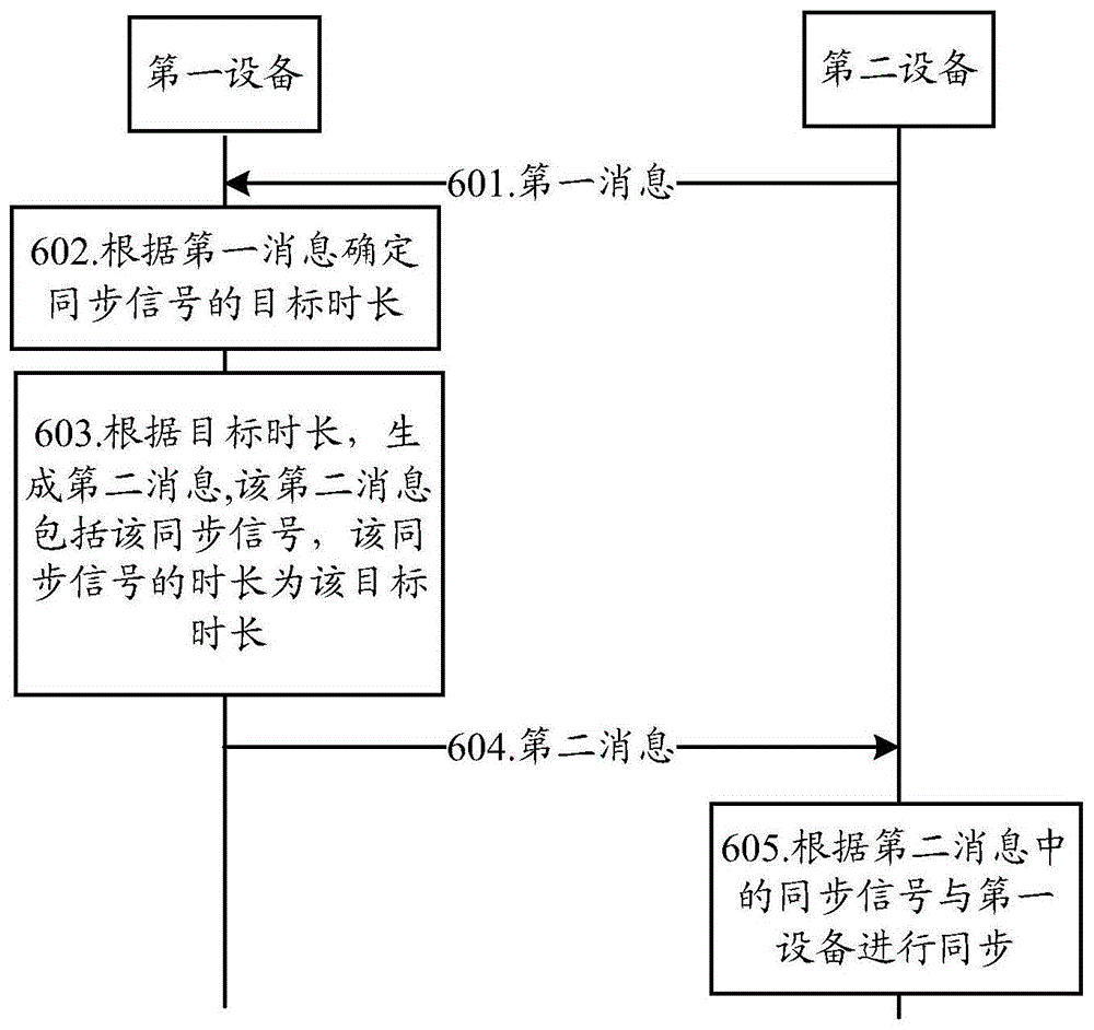
Fig. 6 shows a schematic flow chart of a method of signal processing according to an embodiment of the present application.
601. The second device sends a first message to the first device.
In the embodiment of the application, the first device comprises a host communication module, the second device comprises a host communication module and a WUR module, or the first device may further comprise a WUR module. The first device is a device that sends a wakeup radio frequency frame and the second device is a device that receives the wakeup radio frequency frame.
For example, the first device may be an AP (e.g., a router), the second device may be a STA (e.g., a handset); or the first device may be a STA (e.g., a cell phone) and the second device may be a wearable device, such as a bracelet. The first device and the second device may also be other devices and the like having the corresponding functions described above, but the present application is not limited thereto.
The first device may receive the first message through the host communication interface or the WUR interface. The synchronization signal is composed of a plurality of repeated signal waveforms, where the time duration of the synchronization signal may be represented by the time domain length of the synchronization signal, may also be represented by the number of repeated signal waveforms included in the synchronization signal waveform, and may also be the bit length of the synchronization sequence corresponding to the synchronization signal, which is not limited in this application.
In some scenarios, two devices may have WUR transceiving capabilities at the same time, and the roles of the two devices depend on the current communication scenario. For example, both a mobile phone and a bracelet may have WUR transceiving capabilities and have power saving requirements, and therefore, they can simultaneously operate in a WUR operating mode, but need to inform the other party of their own wake-up window rules. Specifically, when data of the mobile phone is sent to the bracelet, the mobile phone sends a wake-up packet to the bracelet in a wake-up window of the bracelet, wherein the mobile phone is the first device and the bracelet is the second device; when the data of the bracelet is sent to the mobile phone, the wakeup package is sent to the mobile phone in the wakeup window of the mobile phone, and at the moment, the bracelet is the first device and the mobile phone is the second device.
It should be understood that the WUR module may be represented by the first interface and the host communication module may be represented by the second interface in the embodiments of the present application, and the WUR module or the WUR interface may not be distinguished, and the host communication module and the host communication interface may not be distinguished.
Optionally, as an embodiment, the second device determines an expected duration of the synchronization signal, where sending, by the second device, the first message to the first device includes: the second device sends the first message carrying the expected duration of the synchronization signal to the first device.
As shown in fig. 7, the second device determines the duration of the synchronization signal (denoted as the desired duration) needed to complete synchronization with the first device, which may be the duration of the synchronization signal determined to be desired based on the capabilities of its first interface (i.e., WUR module) and reported to the first device. The reception capability of the WUR module itself is usually determined at the time of shipment of the device, and thus may be reported to the first device as a piece of basic capability information. Or the second device may also determine, according to other information, a duration of the synchronization signal that is expected by the second device, which is not limited in this application.
For example, the first message may be an Association Request (Association Request)/Response frame (Response frame) containing the duration of the expected synchronization signal, i.e., the length of the synchronization signal expected by the WUR module that the second device may report during Association. At this time, the first message is transmitted through the second interface (i.e., the master communication module).
The second equipment sends a first message carrying expected duration to the first equipment, and the first messageMay be a management frame, a data frame, or may also be a control frame. For example, as shown in fig. 8, the first message is a management frame containing a specially defined preset length for carrying the synchronization signal (assuming that the expected duration is L)0) The synchronization signal Element (IE). The first message is a control frame, and L is carried in the control domain of the frame in a piggyback (piggyback) mode0The synchronization signal length L expected by the second device is carried by using a High Throughput (HT)/Very High Throughput (VHT)/High Efficiency (HE) Control (Control) field or Quality of Service (QoS) Control field in the 802.11n/ac/ax data Frame, or a Frame (Frame) Control field of a Control Frame, etc0. As shown in fig. 9, the reserved bits in the Frame Control field of the Control Frame (e.g., Request To Send (RTS)/Clear To Send (CTS)/Acknowledgement (ACK), etc.) carry L0Wherein, the bit with value of 0 is reserved bit and can be used for carrying L0。
Optionally, as an embodiment, the target duration of the synchronization signal in the second message may be divided into several steps, and the identifier of the target duration of the synchronization signal, which may be used when the second device expects the first device to send the second message, may be indicated in the first message. For example, the target duration of the synchronization signal in the second message may be in the fourth gear of 8bits, 16bits, 24bits, and 32bits, and the identifier may be 0, 1, 2, and 3, respectively, and then the identifier of the target duration of the synchronization signal used when the first device sends the second message, which is expected by the second device, may be indicated by 2bits in the first message. If the target duration of the synchronization signal in the second message is only divided into two steps, for example, 8bits and 16bits, only 1bit in the first message is needed to indicate, for example, 0 represents 8bits, and 1 represents 16 bits. In the above description, the target duration of the synchronization signal in the second message is represented by the sequence bit length of the synchronization signal, and equivalently, the target duration of the synchronization signal in the second message can also be represented by the time domain length of the synchronization signal, for example, 32 μ s, 64 μ s, etc. In all embodiments of the present invention, the target duration of the synchronization signal in the second message may be represented by the sequence bit length of the synchronization signal, or may be replaced by the time domain length of the synchronization signal, which is equivalent to the target duration of the synchronization signal in the second message.
Optionally, before the first device receives the first message sent by the second device, the first device sends a third message for measuring the channel quality of the third channel to the second device, the second device determines the channel quality measurement result of the third channel according to the third message, and determines the expected duration of the synchronization signal according to the channel quality measurement result of the third channel.
It should be noted that, for convenience of distinction and description in the embodiments of the present application, a channel used by the second device to send the first message is referred to as a "first channel", and a channel used by the first device to send the third message to the second device is referred to as a "third channel". The first channel and the third channel may be the same or different.
The third message may be a WUR frame, i.e., the first device sends a WUR frame based on which the second device measures the third channel. That is, before the second device sends the first message through the second interface, the first device may send, to the second device, a third message, where the third message is used to measure the channel quality in a third channel in a direction from the first device to the second device (which may be denoted as the first direction), and the second device determines a channel quality measurement result of the third channel according to the third message, and estimates a length of a synchronization signal expected by itself (which is denoted as an expected duration) according to the channel quality measurement result, so as to report the third message to the first device through being carried in the first message.
The Channel Quality measurement result may be Channel Quality Information (CQI), Channel State Information (CSI), or Signal-Noise Ratio (SNR), etc.
Optionally, as an embodiment, as shown in fig. 10, the first device sends a third message for measuring the channel quality of the third channel to the second device, and the second device determines the channel quality measurement result of the third channel according to the third message, and sends the channel quality measurement result carried in the first message to the first device.
Specifically, the channel quality measurement result may be CQI, CSI, SNR, or the like. Specifically, the first message carrying the channel quality measurement result may be a management frame (as shown in fig. 8). The third message may be a dedicated channel measurement message, such as a Null Data Packet (NDP) channel Sounding message (Sounding). At this time, the first device should also send a measurement notification message before sending the third message to notify the second device of which channels to measure, as shown in fig. 11 (the sending of the subsequent third message is omitted in the figure), it should be noted that the measurement notification message that may exist before the third message is not drawn in fig. 10. The method has higher flexibility, and can be used even if the main channel and the WUR channel of the main communication module are completely different, for example, the main channel of the main communication module is channel 1, the WUR channel is in channel 2, and the two channels are not overlapped, so that the first device can send measurement notification information in channel 1 to instruct the second device to subsequently receive NDP Sounding on channel 2 so as to measure channel 2; the third message can also be other messages sent by the main communication module, such as a Beacon (Beacon) frame sent periodically, and the method has the advantage that no special measurement message needs to be sent, so that the overhead is small.
The embodiment of the present application may refer to the channel quality measurement result for determining the first direction of the third channel through the third message as "explicit feedback", which has an advantage of higher accuracy. The second device feeds back in the first message the channel quality measurements that should contain at least the measurements of the channel used to send the second message, denoted second channel. Of course, the measurement result of the entire channel (i.e., the first channel) may be further included.
Optionally, as an embodiment, the channel quality measurement result may also be an equivalent representation of a Modulation Coding Scheme (MCS) recommended by the second device, that is, the second device recommends an MCS in the first message, so that the first device may approximately estimate an approximate channel condition from the first device to the second device according to the MCS recommended by the second device since the MCS generally has a corresponding relationship with the channel quality.
For example, in the current 802.11 standard, the second device may piggyback (piggyback) a recommended MCS in the HT Control field of the data frame, and the first device may estimate the preset length using the recommended MCS, so that a special measurement procedure is not required to measure the channel, thereby further reducing overhead.
Alternatively, as an embodiment, in the case that the target duration of the synchronization signal in the second message is only divided into two steps, the design of the first message may be more simplified. For example, the target duration of the synchronization signal in the second message may only be two types, i.e. 8bits and 16bits, and the first message sent by the second device to the first device may not contain any channel quality measurement result and expected length L of the synchronization signal0Etc. but only to indicate that the first message is a synchronization signal target duration switch message (which may be indicated by a frame type, an indicator bit, or other means). The target duration of the synchronization signal used for sending the second message to the second device is switched each time the first device receives a first message from the second device. And before the new first message is not received, the target time length of the synchronization signal used by the first equipment for sending the second message is kept unchanged. For example, if the first device originally uses 8bits as the target duration of the synchronization signal of the second message, after receiving a first message, the first device switches the target duration of the synchronization signal of the second message of the second device to 16bits, and before receiving the next first message from the second device, the target duration of the synchronization signal in the second message sent by the first device to the second device is always 16 bits; and when the first equipment receives the first message from the second equipment again, the target time length of the synchronous signal in the second message sent to the second equipment by the first equipment is switched to 8 bits. The device identification of the second device is obviously carried in the first message so that the first device identifies from which device the first message came.
There may be different schemes for when the second device sends the first message. In a first scheme, the second device may reuse an Association Request (Association Request)/Association Response (Association Response) frame or a Reassociation Request (Association Request)/Reassociation Response (Reassociation Response) frame as the first message, which obviously occurs during the Association/Reassociation phase of the second device with the first device. In a second scheme, the second device may send the first message incidentally during the second interface communication with the first device, for example, the second device piggybacks (piggyback) the recommended MCS in the HT Control field in the data frame, or takes the data frame sent by the second device as the first message, so that the first device measures the channel based on the first message. This occurs when the second interface of the second device is active and is interacting with data of the first device. In a third scheme, when the second device considers that the target of the synchronization signal for the first device to transmit the second message needs to be modified, the second device may transmit a dedicated management frame or control frame or NDP frame as the first message and transmit the first message to the first device through the second interface. All the three schemes are used when the second interface is in an activated state.
However, the second device may be in a state of closing the second interface and opening the first interface in many cases, and if the second device moves in this state and changes the channel quality, the first device should also be able to timely learn the change of the channel state, so as to change the target duration of the synchronization signal. In a fourth scheme, the second device in the above state may periodically send a first message, where such a first message may be sent via the first interface (if the first interface has the sending capability), or sent via the second interface. For the latter, the second interface of the second device needs to be activated periodically to send the first message. In a fifth scheme, the second device may receive, through the first interface, a third message sent by the first device, where the third message may be, for example, a wakeup frame sent by the first device to another device through the first interface, or the third message may be a WUR Beacon frame sent by the first device through the first interface, and the second device may measure the received power of the third message, so as to estimate the channel. When the second device finds that the channel state has changed greatly, the second device sends a first message through the first interface, or the second device activatesThe second interface sends the first message. For example, when the second device finds that the MCS that can be recommended to the first device is changed from MCS1 to MCS0 according to the measurement of the third message, the second interface is activated to send the first message to the first device. The first message in the fourth and fifth schemes may be any of the aforementioned first messages, such as an NDP frame, a first message carrying a target duration indicator, and a first message carrying an L0Or the first message carrying the channel quality measurement result, etc. For the fifth scheme, the second device may determine whether to send the first message and a specific value of the recommended content in the first message according to an SNR (Signal-to-Noise Ratio) or a received Signal strength of the received third message. Taking the example that the first message indicates the recommended MCS of the second message, when the second device detects that the SNR of the third message is determined by the SNR>Thr becomes SNR<Thr, then the second device sends the first message with MCS0 indicated therein; when the second device detects the SNR of the third message is determined by the SNR<Thr becomes SNR>Thr, the second device sends the first message with MCS1 indicated therein. In order to avoid that the second device frequently switches between two states due to the back and forth movement of the second device, and further the second device frequently sends the first message, which causes the increase of transmission overhead and power consumption, a viscosity coefficient (Δ) method may be introduced. For example, rule 1 is that when the SNR value detected by the second device is determined by SNR>Thr-delta becomes SNR<Thr- Δ, MCS0 is indicated in the first message. As another example, rule 2 is that when the second device detects that the SNR value is equal to or greater than the SNR<Thr + Delta becomes SNR>Thr + Δ, MCS1 is indicated in the first message. Δ may be a value predefined by a standard, or a value that the first device configures to the second device. The same holds true for Thr. Wherein, Delta>0. It should be noted that rule 1 and rule 2 are independent of each other and do not require simultaneous use. Considering that a longer synchronization signal can be used when the second device is closer to the first device, and a shorter synchronization signal cannot be used when the second device is farther from the first device, a reasonable rule is: when the SNR value detected by the second device is determined by SNR>Thr becomes SNR<Thr, MCS0 is indicated in the first message; when the SNR value detected by the second device is determined by SNR<Thr + Delta becomes SNR>Thr+ΔMCS1 is indicated in the first message. The substitution of SNR for received signal strength in the above discussion is also similar and will not be described in detail. The above rule is applicable to any situation where the target time length of the two-shift second message synchronization signal is switched.
When the second interface of the second device is in an activated state, one or more of the first, second and third schemes may be adopted. When the second device is in a state where the second interface is off and the first interface is on, one or more of the fourth and fifth schemes may be adopted.
There may be multiple second devices associated with the first device. The first device should save the second message synchronization signal target duration for each second device. When the first device receives a first message from the second device again and determines a second message synchronization signal target duration different from the stored value according to the first message, the first device may update the stored second message synchronization signal target duration corresponding to the second device to the re-determined second message synchronization signal target duration. And when the first equipment sends the second message to the second equipment, the stored second message synchronization signal target time length corresponding to the second equipment is always used.
602. The first device determines a target duration of the synchronization signal based on the first message.
Optionally, if the expected duration of the synchronization signal is carried in the first message, the first device determines the target duration according to the expected duration.
When the first device receives the expected duration (denoted as L) sent by the second device through the second interface or the first interface0) Then according to L0A target duration (denoted L) of the synchronization signal is determined. L is not less than L0Preferably, L ═ L0. As shown in fig. 7, the second message omits a possible Legacy Preamble, and the following figures all adopt a similar manner, but the present application is not limited thereto.
Optionally, the first message carries a channel quality measurement result of the third channel, and the first device determines the target duration of the synchronization signal according to the channel quality measurement result.
And before the second equipment sends the first message through the second interface, the first equipment sends a third message to the second equipment so that the second equipment can measure a third channel according to the third message and obtain a third channel quality measurement result. Subsequently, the second device reports the channel quality measurement result to the first device through the first message. In general, the better the channel quality, the smaller the target duration; the worse the channel quality, the larger the target duration.
Optionally, as an embodiment, the first device receives, at a first channel, the first message sent by the second device, and the first device may measure the channel quality of the first channel according to the first message and generate a channel quality measurement result of the first channel, and further may determine the target duration of the synchronization signal according to the channel quality measurement result of the first channel.
From the channel reciprocity, it is assumed that the channel quality between the first device and the second device is approximately equivalent in both directions, so the measurement of the first channel from the second device to the first device (denoted as second direction) is considered as the measurement of the channel quality of the first channel from the first device to the second device (denoted as first direction), which may be referred to as "implicit feedback". That is, the first message is sent by the second device as a channel measurement message, the first device measures the first channel according to the first message and generates a channel quality measurement result, and then determines the target duration of the synchronization signal based on the channel quality measurement result. As shown in fig. 12, the Channel Quality measurement result may specifically be Channel Quality Information (CQI), Channel State Information (CSI), or the like. By 'implicit feedback', the channel quality can be known without separately sending channel measurement information, thereby reducing the overhead.
The first message in this embodiment is similar to the third message, and the first message may be a dedicated channel measurement message, such as NDP Sounding, or may be another frame, such as a data frame, a management frame, or a control frame. The first device measures a channel based on the first message. Similarly, the first message may be sent over a first interface (WUR) and may also be sent over a second interface. The first message is preferably sent over the second interface, considering that the second device often does not have WUR transmission capability.
Optionally, the method further comprises: the first equipment receives receiving capability information sent by the second equipment, wherein the receiving capability information represents the receiving capability of the second equipment for receiving a second message; wherein the determining, by the first device, the target duration of the synchronization signal according to the channel quality measurement result includes: the first device determines a target duration of the synchronization signal according to the channel quality measurement result and the receiving capability information.
Whether the second device determines L based on channel quality measurements0In this case, or when the first device determines L based on the channel quality measurement result fed back by the second device, the receiving capability information of the second device for receiving the second message (i.e., the receiving capability information of the second device for receiving the wake-up rf frame) may need to be considered, and in this embodiment, the "wake-up rf frame" is expressed as "the second message". The "receiving capability" here may be a receiving capability of the second device to receive the same kind of second message (e.g. same frame format) or different kind of second message (e.g. different frame format).
For example, the first device determines the length of the synchronization signal based on the channel quality measurement result to be L1The length of the synchronization signal determined based on the WUR reception capability information of the second device is L2Then L finally determined0Or L should be the larger of the two, i.e., max { L }1,L2}。
Since the length of the synchronization signal of the WUR frame mainly affects the receiving performance of the second device, and the WUR frame is transmitted by the first device and received by the second device, the self-receiving capability fed back by the second device and the measurement result of the channel from the first device to the second device are both most direct and accurate for the first device to determine the length of the synchronization signal of the WUR frame.
Optionally, if the second message is a unicast frame, that is, there is only one second device, the first device determines the length L of the synchronization signal according to the first message sent by the second device; if the second message is a multicast frame or a broadcast frame, that is, there are a plurality of second devices, the first messages fed back by the plurality of second devices respectively need to be considered. Specifically, if the receiving object of the second message is a plurality of known determination devices (for example, the first device is an AP, and the second device is a plurality of STAs associated with the AP), the length L of the synchronization signal of the second message should be considered according to the most conservative one of the plurality of second devices, for example, if L determined by the AP based on the first message sent by each of the three STAs is 30, 35, or 27 (unit: number of repeated waveforms), the length of the synchronization signal sent by the AP should be the maximum value 35 of the three; if the reception target of the first device is ambiguous (for example, the first device is an AP, and the second device includes both an associated STA and a non-associated STA, which will not transmit the first message like the AP), the length L of the synchronization signal of the second message should be the maximum allowed value of the length of the synchronization signal, i.e. considered according to the most conservative case.
In addition, the first device determines the target duration according to the channel quality, specifically, the target duration may be determined according to the distance between the first device and the second device, the transmission power and the like, so that the probability that the STA at a far distance receives the WUR frame is reduced, the security of second message transmission is improved, and the method has great significance when being applied to wearable devices.
603. And the first equipment generates a second message according to the target time length of the synchronous signal, wherein the second message comprises the synchronous signal, and the time length of the synchronous signal is the target time length.
The first device determines a target duration of the synchronization signal, and generates a wake-up rf Frame (denoted as a second message) according to a Frame format of the system, where the wake-up rf Frame may include the synchronization signal, a Start Frame Delimiter (SFD), a signaling field, and/or the like. The first device may generate wake-up rf frames in different formats for different systems, as long as the wake-up rf frames include a synchronization signal, and the format of the wake-up rf frames is not limited in the present application.
The shortest synchronization signal length required for the WUR interface of different second devices to receive a WUR frame may be different. This is due to several reasons:
1. the receiver capabilities of different devices vary. For example, the WUR of a mobile phone has higher accuracy and reception performance, and synchronization can be successfully completed by a shorter synchronization signal; sensors (e.g., sensors for forest monitoring) must be inexpensive due to the need for large-scale deployment, and accordingly their configured WURs are less accurate and require longer synchronization signals to complete synchronization.
2. The longer the same device is used, the lower the accuracy due to device aging, and the longer the synchronization signal is required to complete synchronization. For example, sensor devices are expected to operate for 5-10 years, such a long time, coupled with the potentially harsh environment (e.g., a sensor in forest monitoring exposed to wind, rain, and sun), device aging is significant.
3. As technology develops and advances, shorter synchronization signals are needed to perform the synchronization function. For example, from the original 802.11 to 802.11b, the synchronization signal length becomes shorter.
4. Distance and transmit power. The shorter the distance between the first device and the second device is, the larger the transmitting power of the first device is, and the smaller the length of a synchronization signal required by the second device to complete synchronization is; conversely, the larger the distance, the smaller the transmission power, the longer the length of the synchronization signal required by the second device to complete synchronization.
Among the above four factors, the Capability of the receiver itself is determined when the device leaves the factory, and the reduction of the length of the synchronization signal caused by the technical progress is also determined when the device leaves the factory, so that the Capability of the receiver itself can be unified; device aging, distance and transmit power variations resulting in variations in the length of the synchronization signal can all be attributed to the effect of the channel between the first device and the second device.
On the other hand, variations in the length of the synchronization signal do not lead to increased complexity of the receiver implementation. Instead of detecting a predefined number of synchronization signal repetition waveforms from the received signal, the receiver first detects the predefined repetition waveforms and, after synchronizing based on the detection of the predefined repetition waveforms, detects a predefined sequence (i.e., SFD) of signals, which is considered to be the start of the frame. In other words, the receiver does not count the number of repeated waveforms when performing synchronization based on the synchronization signal, and the start position determination of the frame is determined by the subsequent SFD. The change of the length of the synchronization signal is caused by the change of the number of the repeated waveforms contained in the synchronization signal, and the change of the length of the synchronization signal has no influence on the implementation of the second device as long as the second device completes synchronization.
Obviously, the worse the channel quality, the longer the target duration of the synchronization signal in the second message should be; the better the channel quality, the shorter the synchronization signal target duration in the second message can be. At the same time, the MCS of the MAC portion of the second message may be adjusted accordingly. For example, the worse the channel quality, the lower the MCS of the MAC portion of the second message may be; the better the channel quality, the higher the MCS of the MAC portion of the second message may be. Further, in the second message, the MCS of the MAC part may be indicated by the length of the synchronization sequence. For example, when the length of the synchronization sequence in the second message is 8bits, the MCS of the MAC portion is MCS 1; when the length of the synchronization sequence in the second message is 32bits, the MCS of the MAC part is MCS 0.
604. The first device sends a second message to the second device.
Optionally, the first device sends the second message to the second device through the first interface, wherein a channel (denoted as a third channel) used by the first device to send the third message to the second device should be able to cover a channel (hereinafter referred to as a "second channel" for convenience of description) used to subsequently send the second message. In other words, the second channel used for sending the second message may be the third channel, or may be at least one sub-channel of the third channel, that is, the second channel may be all sub-channels or part of sub-channels of the third channel. For example, the third message is sent using a 20MHz channel, and the second message is sent using some 4MHz channel of the 20MHz channels.
Or the second channel used by the first device to send the second message to the second device may be a first channel used by the second device to send the first message to the first device, or a sub-channel of the first channel.
It should be understood that the third channel used by the first device to send the third message to the second device may be the same as or different from the first channel used by the second device to send the first message to the first device, and this is not limited in this application.
605. The second device synchronizes with the first device according to the synchronization signal in the second message.
According to the embodiment of the application, the first device determines the target time length of the synchronous signal and generates the second message by receiving the first message sent by the second device, and then sends the second message to the second device, so that the second device and the first device are synchronized, and thus the second message sent by the first device to the second device has the synchronous signal which is short and enough for the second device to complete the synchronous function, thereby reducing the waste of media resources and improving the utilization efficiency of media.
It will be appreciated that when there are multiple second devices in the network, the synchronization signals of the second messages sent by the first device to the different second devices may be different, but the length L of the synchronization signals must be chosen to be relatively short but sufficient to support the receiving end to complete synchronization.
It should also be understood that, in various embodiments of the present invention, the sequence numbers of the above-mentioned processes do not mean the execution sequence, and the execution sequence of each process should be determined by its function and inherent logic, and should not constitute any limitation on the implementation process of the embodiments of the present invention.
Therefore, in the signal processing method according to the embodiment of the present application, by receiving the first message sent by the second device, determining the target duration of the synchronization signal according to the first message, generating the second message, and sending the second message used for synchronizing the second device with the first device to the second device, the first device can determine the appropriate target duration of the synchronization signal according to the first message sent by the second device, and send the second message including the target duration of the synchronization signal to the second device, thereby avoiding waste of channel resources caused by sending the second message including redundant duration of the synchronization signal, and improving the utilization rate of the channel resources.
FIG. 13 shows an interactive flow diagram of a method of signal processing according to one embodiment of the present application. The meanings of various terms in the embodiments of the present application are the same as those of the previous embodiments.
It should be noted that this is only for helping the skilled person to better understand the embodiments of the present application, and does not limit the scope of the embodiments of the present application.
1301, a first device receives a first message on a first channel, the first channel comprising at least one subchannel.
The first device determines 1302 a channel quality measurement for the first channel based on the first message.
1303, the first device determines a target duration of the synchronization signal according to the channel quality measurement result of the first channel.
And 1304, the first device generates a second message according to the target time length, wherein the second message comprises the synchronous signal, and the time length of the synchronous signal is the target time length.
1305, the first device sends the second message to the second device on at least one sub-channel in the first channel.
The second device synchronizes 1306 with the first device based on the synchronization signal in the second message.
Therefore, in the signal processing method of the embodiment of the present application, the first device receives the first message sent by the second device on the first channel, determining a channel quality measurement result of a first channel according to the first message, determining a target duration of a synchronization signal according to the channel quality measurement result of the first channel, generating a second message, transmitting a second message to the second device on a subchannel of the first channel for the second device to synchronize with the first device, the first device is thus able to determine a channel quality measurement from the first message as a measurement message, and determines a target duration of the appropriate synchronization signal based on the channel quality measurement and sends a second message including the target duration of the synchronization signal to the second device, therefore, the waste of channel resources caused by sending the second message comprising the redundant synchronizing signal duration is avoided, and the utilization rate of the channel resources is improved.
Fig. 14 shows an interaction flow diagram of a method of signal processing according to another embodiment of the present application. The meanings of various terms in the embodiments of the present application are the same as those of the previous embodiments.
It should be noted that this is only for helping the skilled person to better understand the embodiments of the present application, and does not limit the scope of the embodiments of the present application.
1401, the first device transmits a third message on a third channel, the third channel comprising at least one sub-channel.
1402, the second device measures a channel quality measurement result of the third channel according to the third message.
1403, the second device determines the preset length of the synchronization signal according to the channel quality measurement result of the third channel.
The second device sends 1404 a first message carrying a desired duration.
1405, the first device determines a target duration based on the desired duration.
1406, the first device generates a second message according to the target duration, where the second message includes the synchronization signal, and the duration of the synchronization signal is the target duration.
1407, the first device transmits the second message to the second device on a sub-channel of the third channel.
1408, the second device synchronizes with the first device according to the synchronization signal in the second message.
Therefore, in the method for processing a signal in the embodiment of the present application, the first device sends, to the second device, a third message for performing channel measurement on the third channel, so that the second device determines a channel quality measurement result of the third channel according to the third message, and determines an expected duration of a synchronization signal required by the second device according to the channel quality measurement result, the second device sends, to the first device, a first message carrying the expected duration of the synchronization signal, the first device determines a target duration of the synchronization signal according to the expected duration of the synchronization signal and generates a second message, the first device sends, to the second device, a second message used for synchronizing the second device with the first device, so that the first device can determine a suitable target duration of the synchronization signal according to the expected duration of the synchronization signal sent by the second device, and send, to the second device, the second message including the target duration of the synchronization signal, therefore, the waste of channel resources caused by sending the second message comprising the redundant synchronizing signal duration is avoided, and the utilization rate of the channel resources is improved.
Fig. 15 shows an interaction flow diagram of a method of signal processing according to another embodiment of the present application. The meanings of various terms in the embodiments of the present application are the same as those of the previous embodiments.
It should be noted that this is only for helping the skilled person to better understand the embodiments of the present application, and does not limit the scope of the embodiments of the present application.
1501, the second device receives a third message sent by the first device on a third channel, the third message being used for measuring the channel quality of the third channel, and the third channel comprising at least one sub-channel.
1502, the second device determines a channel quality measurement result of the third channel according to the third message.
1503, the second device sends a first message carrying the channel quality measurement to the first device.
1504, the first device determines a target duration based on the channel quality measurements.
1505, the first device generates a second message comprising the synchronization signal according to a target duration, the duration of the synchronization signal being the target duration.
The first device sends 1506 the second message to the second device on a subchannel of the third channel.
1507 the second device synchronizes with the first device according to the synchronization signal in the second message.
Therefore, in the signal processing method according to the embodiment of the present application, the first device sends, to the second device, a third message for performing channel measurement on the third channel, so that the second device determines a channel quality measurement result of the third channel according to the third message, the second device sends, to the first device, a first message carrying the channel quality measurement result, the first device determines a target duration of the synchronization signal according to the channel quality measurement result and generates a second message, the first device sends, to the second device, a second message for synchronizing the second device with the first device, so that the first device can determine a suitable target duration of the synchronization signal according to the channel quality measurement result sent by the second device and send, to the second device, the second message including the target duration of the synchronization signal, thereby avoiding waste of channel resources caused by sending the second message including redundant duration of the synchronization signal, the channel resource utilization rate is improved.
It should be understood that, in the various embodiments of the present application, the sequence numbers of the above-mentioned processes do not mean the execution sequence, and the execution sequence of each process should be determined by its function and inherent logic, and should not constitute any limitation to the implementation process of the embodiments of the present application.
Having described the method of signal processing according to an embodiment of the present application in detail above, an apparatus of signal processing according to an embodiment of the present application will be described below.
Fig. 16 shows a schematic block diagram of a first device according to an embodiment of the present application. As shown in fig. 16, the first apparatus 1600 includes:
a receiving module 1610, configured to receive a first message sent by a second device;
a processing module 1620, configured to determine a target duration of the synchronization signal according to the first message received by the receiving module 1610;
the processing module 1620 is further configured to generate a second message according to the target duration of the synchronization signal determined by the processing module 1620, where the second message includes the synchronization signal, and the duration of the synchronization signal is the target duration;
a sending module 1630, configured to send the second message generated by the processing module 1620 to the second device.
Therefore, according to the first device of the embodiment of the application, the target duration of the synchronization signal is determined and the second message is generated by receiving the first message sent by the second device, the second message includes the synchronization signal, and the duration of the synchronization signal included in the second message is the target duration, and then the second message is sent to the second device, so that the second device and the first device are synchronized, and thus the second message sent by the first device to the second device has a shorter synchronization signal which is enough for the second device to complete the synchronization function, thereby reducing the waste of media resources and improving the utilization efficiency of media.
Optionally, the first message carries an expected duration of the synchronization signal, where the expected duration of the synchronization signal represents a duration of the synchronization signal required by the second device to complete synchronization with the first device; the processing module 1620 is specifically configured to: and determining a target time length of the synchronous signal according to the expected time length, wherein the target time length is not less than the expected time length.
Optionally, the sending module 1630 is further configured to send a third message to the second device on the first channel, so that the second device measures the channel quality of the first channel according to the third message, generates a channel quality measurement result of the first channel, and determines the expected duration of the synchronization signal according to the channel quality measurement result of the first channel.
Optionally, the receiving module 1610 is further configured to receive, by the first device, the first message sent by the second device on a first channel; the processing module 1620 is specifically configured to: measuring channel quality of the first channel according to the first message and generating a channel quality measurement result of the first channel; and determining the target time length of the synchronous signal according to the channel quality measurement result of the first channel.
Optionally, the sending module 1630 is further configured to send a third message to the second device on the first channel, where the third message is used for the second device to measure the channel quality of the first channel and generate a channel quality measurement result of the first channel; the first message carries a channel quality measurement result of the first channel; the processing module 1620 is specifically configured to: and determining the target time length of the synchronous signal according to the channel quality measurement result of the first channel.
Optionally, the receiving module 1610 is further configured to receive receiving capability information sent by the second device, where the receiving capability information indicates a receiving capability of the second device to receive the second message; the processing module 1620 is specifically configured to: and determining the target time length of the synchronous signal according to the channel quality measurement result of the first channel and the receiving capability information.
Optionally, the first channel comprises at least one sub-channel; the sending module 1630 is specifically configured to: the second message is sent to the second device on at least one subchannel in the first channel.
Therefore, according to the first device of the embodiment of the application, the target duration of the synchronization signal is determined and the second message is generated by receiving the first message sent by the second device, the second message includes the synchronization signal, the duration of the synchronization signal included in the second message is the target duration, and the second message is sent to the second device, so that the second device and the first device are synchronized, and thus the second message sent by the first device to the second device has the synchronization signal which is shorter and is enough for the second device to complete the synchronization function, thereby reducing the waste of media resources and improving the media utilization efficiency.
The first device according to the embodiment of the present application may correspond to an execution main body of the method for signal processing according to the embodiment of the present application, and the above and other operations and/or functions of each module in the first device are respectively for implementing corresponding flows of the foregoing methods, and are not described herein again for brevity.
Fig. 17 shows a schematic block diagram of a first device according to an embodiment of the application. As shown in fig. 17, the second apparatus 1700 includes:
a sending module 1710, configured to send a first message to a first device, where the first message is used for the first device to determine a target duration of a synchronization signal, and generate a second message, where the second message includes the synchronization signal, and a duration of the synchronization signal is the target duration;
a receiving module 1720, configured to receive the second message sent by the first device;
a processing module 1730, configured to synchronize with the first device according to the synchronization signal in the second message.
Therefore, the second device in the embodiment of the application, by sending the first message to the first device, determines the target duration of the synchronization signal according to the first message, and generates the second message according to the target duration, where the second message includes the synchronization signal, and the duration of the synchronization signal included in the second message is the target duration, and then receives the second message sent by the first device, and the second device synchronizes with the first device according to the synchronization signal in the second message, so that the second message received by the second device is a synchronization signal that is relatively short and is enough for the second device to complete a synchronization function, thereby reducing media resource waste and improving media utilization efficiency.
Optionally, the processing module 1730 is further configured to determine an expected duration of the synchronization signal, where the expected duration of the synchronization signal represents a duration of the synchronization signal required by the second device to complete synchronization with the first device; the sending module 1710 is specifically configured to: and sending the first message carrying the expected duration of the synchronization signal to the first device.
Optionally, the receiving module 1720 is further configured to receive, by the second device, a third message, where the third message is used to measure the channel quality of the first channel; the processing module 1730 is further configured to determine a channel quality measurement result of the first channel according to the third message; the processing module 1730 is specifically configured to: and determining the expected time length of the synchronization signal according to the channel quality measurement result of the first channel.
Optionally, the receiving module 1720 is further configured to receive a third message, where the third message is used to measure the channel quality of the first channel; the processing module 1730 is further configured to determine a channel quality measurement result of the first channel according to the third message; the processing module 1730 is specifically configured to: and sending the first message carrying the channel quality measurement result of the first channel to the first equipment.
Therefore, the second device in the embodiment of the application, by sending the first message to the first device, determines the target duration of the synchronization signal according to the first message, and generates the second message according to the target duration, where the second message includes the synchronization signal, and the duration of the synchronization signal included in the second message is the target duration, and then receives the second message sent by the first device, and the second device synchronizes with the first device according to the synchronization signal in the second message, so that the second message received by the second device is a synchronization signal that is relatively short and is enough for the second device to complete a synchronization function, thereby reducing media resource waste and improving media utilization efficiency.
The second device according to the embodiment of the present application may correspond to an execution main body of the method for signal processing according to the embodiment of the present application, and the above and other operations and/or functions of each module in the second device are respectively for implementing corresponding flows of the foregoing methods, and are not described herein again for brevity.
Fig. 18 shows a system 1800 for signal processing according to an embodiment of the application, the system 1800 comprising:
a first device 1600 in the embodiment shown in fig. 16 and a second device 1700 in the embodiment shown in fig. 17.
Fig. 19 shows a schematic structural diagram of a first device provided in an embodiment of the present application. As shown in fig. 19, the first device includes at least one processor 1902 (e.g., a general purpose processor CPU, Digital Signal Processor (DSP), Application Specific Integrated Circuit (ASIC), an off-the-shelf programmable gate array (FPGA), etc., with computing and processing capabilities), the processor 1902 is configured to manage and schedule modules and devices within the first device. The processing module 1620 in the embodiment shown in fig. 16 may be implemented by the processor 1902. The first device also includes at least one transceiver 1905 (receiver/transmitter 1905), memory 1906, and at least one bus system 1903. The receiving module 1610 and the transmitting module 1630 in the embodiment shown in fig. 16 may be implemented by the transceiver 1905. The various components of the first device are coupled together by a bus system 1903, where the bus system 1903 may include a data bus, a power bus, a control bus, and a status signal bus, etc., although the various buses are labeled as bus system 1903 in the figures for clarity of illustration.
The methods disclosed in the embodiments of the present application may be applied to the processor 1902, or may be used to execute executable modules, such as computer programs, stored in the memory 1906. The Memory 1906 may include a high-speed Random Access Memory (RAM) and a non-volatile Memory (non-volatile Memory), and may include a read-only Memory and a Random Access Memory (RAM) and provide necessary signaling or data, programs, and the like to the processor. The portion of memory may also include non-volatile row random access memory (NVRAM). The communication connection with at least one other network element is achieved through at least one transceiver 1905 (which may be wired or wireless).
In some embodiments, the memory 1906 stores the programs 19061, and the processor 1902 executes the programs 19061 to perform the following:
receive, via the transceiver 1905, a first message sent by the second device;
determining a target time length of the synchronization signal according to the first message;
generating a second message according to the target time length of the synchronous signal, wherein the second message comprises the synchronous signal, and the time length of the synchronous signal is the target time length;
the second message is sent to the second device via transceiver 1905.
It should be noted that the first device may be embodied as the first device in the embodiment shown in fig. 16, and may be configured to execute each step and/or flow corresponding to the first device in the method embodiments shown in fig. 6, fig. 13, fig. 14, and fig. 15.
It can be seen from the above technical solutions provided in the embodiments of the present application that, a first device determines a target duration of a synchronization signal and generates a second message by receiving a first message sent by a second device, where the second message includes the synchronization signal, and the duration of the synchronization signal included in the second message is the target duration, and then sends the second message to the second device, so that the second device and the first device are synchronized, and thus, the second message sent by the first device to the second device has a shorter synchronization signal, which is enough for the second device to complete a synchronization function, thereby reducing media resource waste and improving media utilization efficiency.
Fig. 20 shows a schematic structural diagram of a second device provided in an embodiment of the present application. As shown in fig. 20, the second device includes at least one processor 2002 (e.g., a general purpose processor CPU with computing and processing capabilities, a Digital Signal Processor (DSP), an Application Specific Integrated Circuit (ASIC), an off-the-shelf programmable gate array (FPGA), etc.), and the processor 2002 is used to manage and schedule modules and devices within the second device. The processing module 1730 in the embodiment illustrated in fig. 17 may be implemented by the processor 2002. The second device also includes at least one transceiver 2005 (receiver/transmitter 2005), a memory 2006, and at least one bus system 2003. The receiving module 1720 and the transmitting module 1710 in the embodiment shown in fig. 17 may be implemented by a transceiver 2005. The various components of the second device are coupled together by a bus system 2003, where the bus system 2003 may include a data bus, a power bus, a control bus, a status signal bus, etc., although the various buses are labeled as bus system 2003 in the figures for clarity of illustration.
The methods disclosed in the embodiments of the present application described above may be applied to the processor 2002 or used to execute an executable module, such as a computer program, stored in the memory 2006. Memory 2006 may include a high-speed Random Access Memory (RAM) and may also include a non-volatile Memory (non-volatile Memory), which may include both read-only Memory and Random Access Memory, and may provide necessary signaling or data, programs, and so forth to the processor. The portion of memory may also include non-volatile row random access memory (NVRAM). The communication connection with at least one other network element is realized by at least one transceiver 2005 (which may be wired or wireless).
In some embodiments, the memory 2006 stores a program 20061 and the processor 2002 executes the program 20061 for performing the following operations:
sending a first message to a first device through the transceiver 2005, the first message being used for the first device to determine a target duration of a synchronization signal, and generating a second message, the second message including the synchronization signal, the duration of the synchronization signal being the target duration;
receiving, by the transceiver 2005, the second message transmitted by the first device;
the second device synchronizes with the first device according to the synchronization signal in the second message.
It should be noted that the second device may be embodied as the second device in the embodiment shown in fig. 17, and may be configured to perform each step and/or flow corresponding to the second device in the method embodiments shown in fig. 6, fig. 13, fig. 14, and fig. 15.
It can be seen from the above technical solutions provided in the embodiments of the present application that the second device sends the first message to the first device, so that the first device determines the target duration of the synchronization signal according to the first message, and generates the second message according to the target duration, where the second message includes the synchronization signal, and the duration of the synchronization signal included in the second message is the target duration, and then receives the second message sent by the first device, and the second device synchronizes with the first device according to the synchronization signal in the second message, so that the second message received by the second device is a synchronization signal that is short and sufficient for the second device to complete the synchronization function, thereby reducing the waste of media resources and improving the media utilization efficiency.
Embodiments of the present application also provide a computer storage medium that can store program instructions for instructing any one of the methods described above.
Alternatively, the storage medium may be specifically the memory 1906 or 2006.
This application claims priority from prior applications, the entire contents of which are incorporated herein by reference. The following terms have the same meanings as in the foregoing embodiments.
The embodiment of the invention provides a method for reducing Wake-up Preamble aiming at the problem that the Wake-up Preamble occupies a larger proportion in a WUR frame, which can shorten the length of the WUR frame as much as possible, thereby reducing the waste of media resources and improving the utilization efficiency of media.
In one embodiment of the invention: the method comprises the steps that first equipment receives a first message sent by second equipment through a first interface or a second interface, and determines the length L of a synchronous signal based on the first message; the first equipment generates a second message, wherein the second message comprises a first synchronous signal, and the length of the first synchronous signal is L; the first device sends a second message to the second device through the first interface. The signaling interaction and processing flow of this embodiment is shown in fig. 21.
Note that "synchronization signal length" here corresponds to "target time length of synchronization signal" in the above-described embodiment.
The embodiment of the invention ensures that the second message sent by the first equipment to the second equipment has a short synchronous signal which is enough for the second equipment to complete the synchronous function, thereby reducing the waste of media resources and improving the utilization efficiency of media. When there are multiple second devices in the network, the synchronization signals of the second messages sent by the first device to different second devices may be different, but the length L of the synchronization signals is selected to be relatively short but sufficient to support the receiving end to complete synchronization.
In embodiments of the invention, the first interface may be a WUR and, correspondingly, the second message may be a WUR frame. The first message may be received through the first interface or the second interface of the first device, and the second interface may be a primary communication interface, i.e., a WiFi interface or other high speed communication interface, such as LTE. If the first device has no WUR reception capability or the second device has no WUR transmission capability, the first message can only be transmitted through the first interface.
Wherein the first device is a device that transmits a WUR frame and the second device is a device that receives a WUR frame. For example, the first device may be an AP, such as a router, and the second device may be a STA, such as a cell phone; the first device may also be a STA, such as a cell phone, and the second device may be a wearable device, such as a smart phone, a bracelet, and so on. In some scenarios, two devices may have WUR transceiving capabilities at the same time, and the roles of the two devices depend on the current communication scenario. For example, both a mobile phone and a bracelet may have WUR transceiving capabilities and have power saving requirements, and therefore, they can simultaneously operate in a WUR operating mode, but need to inform the other party of their own wake-up window rules. Specifically, when data of the mobile phone is sent to the bracelet, the mobile phone sends a wake-up packet to the bracelet in a wake-up window of the bracelet, wherein the mobile phone is the first device and the bracelet is the second device; when the data of the bracelet is sent to the mobile phone, the wakeup package is sent to the mobile phone in the wakeup window of the mobile phone, and at the moment, the bracelet is the first device and the mobile phone is the second device.
The first synchronization signal is composed of a plurality of repeated signal waveforms. The first synchronization signal length L may be a time domain length of the first synchronization signal, a number of repeated signal waveforms included in the first synchronization signal waveform, or a bit length of a synchronization sequence corresponding to the first synchronization signal. The three meanings are the same in substance and are used to describe the duration of the first synchronization signal.
The first message is a feedback message, and the first device determines a synchronization signal length to be used when a WUR frame (i.e., a second message) is subsequently transmitted, based on the feedback message from the second device. The length of the synchronization signal of the WUR frame sent to the second device may vary, primarily for two reasons:
in one aspect, the shortest synchronization signal length required for the WUR interface of different second devices to receive a WUR frame may be different. This is due to several reasons:
A. the receiver capabilities of different devices vary. For example, the WUR of a mobile phone has higher accuracy and reception performance, and synchronization can be successfully completed by a shorter synchronization signal; sensors (e.g., sensors for forest monitoring) must be inexpensive due to the need for large-scale deployment, and accordingly their configured WURs are less accurate and require longer synchronization signals to complete synchronization.
B. The longer the same device is used, the lower the accuracy due to device aging, and the longer the synchronization signal is required to complete synchronization. For example, sensor devices are expected to operate for 5-10 years, such a long time, coupled with the potentially harsh environment (e.g., a sensor in forest monitoring exposed to wind, rain, and sun), device aging is significant.
C. As technology develops and advances, shorter synchronization signals are needed to perform the synchronization function. For example, from the original 802.11 to 802.11b, the synchronization signal length becomes shorter.
D. Distance and transmit power. The shorter the distance between the first device and the second device is, the larger the transmitting power of the first device for sending the second message is, and the smaller the length of the synchronization signal required by the second device for completing synchronization is; conversely, the larger the distance, the smaller the transmission power, the longer the length of the synchronization signal required by the second device to complete synchronization.
Among the above four factors, the Capability of the receiver itself is determined when the device leaves the factory, and the reduction of the length of the synchronization signal caused by the technical progress is also determined when the device leaves the factory, so that the reduction can be attributed to the Capability of the receiver itself; device aging, distance and transmit power variations resulting in variations in the length of the synchronization signal can all be attributed to the effect of the channel between the first device and the second device.
On the other hand, variations in the length of the synchronization signal do not lead to increased complexity of the receiver implementation. Instead of detecting a predefined number of synchronization signal repetition waveforms from the received signal, the receiver first detects the predefined repetition waveforms and, after synchronizing based on the detection of the predefined repetition waveforms, detects a predefined sequence (i.e., SFD) of signals, which is considered to be the start of the frame. In other words, the receiver does not count the number of repeated waveforms when performing synchronization based on the synchronization signal, and the start position determination of the frame is determined by the subsequent SFD. The change of the length of the synchronization signal is because the number of the repeated waveforms contained in the synchronization signal changes, and the change of the length of the synchronization signal has no influence on the realization of the receiving end as long as the receiving end completes synchronization.
It should be noted that, if the second message is a unicast frame, that is, there is only one second device, the length L of the synchronization signal of the second message only depends on the first message fed back by the second device; if the second message is a multicast frame or a broadcast frame, that is, there are a plurality of second devices, the first messages fed back by the plurality of second devices respectively need to be considered. Specifically, if the expected receiving objects of the second message are a plurality of known determined devices (for example, the first device is an AP, and the second device is a plurality of STAs associated with the AP), the length L of the synchronization signal of the second message should be considered according to the most conservative one of the plurality of second devices, for example, if L determined by the AP based on the first message sent by each of the three STAs is 30, 35, or 27 (unit: number of repeated waveforms), the length of the synchronization signal sent by the AP should be the maximum value 35 of the three; if the expected recipient of the second message is ambiguous (e.g., the first device is an AP and the second device contains both an associated STA and a non-associated STA that will not transmit the first message like the AP), the synchronization signal length L of the second message should be the maximum allowed value of the synchronization signal length, i.e., considered most conservative.
The first embodiment is as follows: the first message is an explicit feedback message
The second device feeds back the first synchronization signal length L0 desired by itself to the first device through the first message, or feeds back channel state information from the first device to the second device. In this embodiment, the first message is transmitted through the second interface (main radio).
The method specifically comprises two conditions:
1) the second device determines a desired first synchronization signal length L0 based on the capabilities of its own first interface (WUR interface) and reports to the first device.
The reception capability of the WUR interface itself is usually determined at the time of shipment of the device and thus may be reported to the first device as a piece of basic capability information. For example, the first message is Association Request/Response frame, which contains the expected first synchronization signal length L0I.e. the second device reports the length L of the synchronization signal expected by its WUR receiver during the association procedure0. At this time, the first message is transmitted through the second interface (i.e., the primary communication interface).
When the first device receives a first message sent by the second device through the second interface, the L reported in the first message is used for indicating the first device to receive the first message0The synchronization signal length L is determined. L is not less than L0Preferably, L ═ L0. The first device then uses L for transmission of the second message on the first interface.
The above process is shown in fig. 21. Note that the second message in fig. 7 omits a Legacy Preamble that may be present for ease of illustration. The following figures are in a similar manner and will not be described in detail. Fig. 22 is a signaling interaction and processing flow of the present solution.
2) The second device measures the channel, and the channel measurement result is based on the channel measurement resultL of fruit0And feeding back to the first equipment through the first message.
Before the second device sends the first message through the second interface, the first device sends a third message to the second device, so that the second device measures the channel based on the third message and obtains a channel measurement result. Then, the second device reports the channel measurement result to the first device through the first message, or the second device estimates the expected synchronization signal length L of the own first interface (WUR interface) based on the channel measurement result0And reports to the first device via the first message.
In this embodiment, the Channel measurement result may specifically be Channel Quality Information (CQI), Channel State Information (CSI), Signal-Noise Ratio (SNR), or the like. The channel measurement result may also be expressed in terms of a recommended MCS equivalent, i.e. the second device recommends an MCS in the first message for use by the first device in sending messages to the second device. Since the MCS generally corresponds to the channel quality, the first device may roughly estimate the rough channel condition from the first device to the second device based on the MCS recommended by the second device, and further determine the length L of the synchronization signal0. In the current 802.11 standard, a receiving end may piggyback (piggyback) a recommended MCS in an HT Control field of a data frame to achieve the purpose of MCS feedback, and this embodiment may estimate L using the recommended MCS0Thus, no special measurement procedure is required to measure the channel, which further reduces overhead.
If the second device reports the expected synchronization signal length L via the first message0Then the first device is according to L0The length L of the synchronization signal is determined as shown in fig. 10, and the signaling interaction and processing flow thereof are shown in fig. 23. L is not less than L0Preferably, L ═ L0。
If the second device reports the channel measurement result through the first message, the first device determines the length L of the synchronization signal based on the channel measurement result, as shown in fig. 11, and the signaling interaction and processing flow thereof are shown in fig. 24. In general, the better the channel quality, the smaller L; the worse the channel quality, the larger L. The first device then uses L for transmission of the second message on the first interface.
The third message may be sent over the first interface, i.e. the first device sends a WUR frame, based on which the second device measures the channel.
The third message may also be sent via the second interface, and at this time, a channel (referred to as a first channel) used for sending the third message should be able to cover a channel (referred to as a second channel) used for subsequently sending the second message, that is, the second channel is a sub-channel of the first channel. For example, the third message is sent using a 20MHz channel, and the second message is sent using some 4MHz channel of the 20MHz channels. If the second device feeds back the channel measurement result in the first message, the channel measurement result at least includes the measurement result of the channel (e.g., the aforementioned 4MHz channel) used for sending the second message. Of course, the measurement results of the entire channel (for example, the aforementioned 20MHz channel) may be further included.
The third message may be a dedicated channel measurement message, such as NDP Sounding, and at this time, the first device should also send a measurement notification message before sending the third message to notify which STAs perform measurement on which channels, as shown in fig. 11 (the sending of the subsequent third message is omitted in the figure), and it is noted that the measurement notification message which may exist before the third message is not shown in fig. 10 and fig. 23. The method has high flexibility, and the main radio channel and the WUR channel can be used even if the main radio channel and the WUR channel are completely different, for example, the main radio channel is channel 1, the WUR channel is in channel 2, and the two channels are not overlapped, so that the first equipment can send measurement notification information in channel 1 and instruct the second equipment to subsequently receive NDP Sounding on channel 2 so as to measure channel 2; the third message may also be other message sent by main radio, such as Beacon frame sent periodically, which has the advantage of no need to send special measurement message and thus the overhead is small, but since the main radio must be sent using the main channel, the method may be difficult to use if the WUR channel does not overlap with the main radio channel.
When the second device feeds back the channel measurement result through the first message, the first message should be a management frame, in which the information is carriedAnd (6) measuring the result. And for the second device in this embodiment, the expected length L of the synchronization signal is fed back by the first message0In the case of (2), the first message may also be a management frame containing a specially defined length L for carrying the synchronization signal0Information Element (IE) of fig. 8, such as the synchronization signal IE shown in fig. 8; the first message may also be a data frame or a control frame, and L is carried in the control domain of the data frame or the control frame by a piggyback (piggyback) method0For example, the HT/VHT/HE Control field or QoS Control field in the 802.11n/ac/ax data Frame, or Frame Control field of the Control Frame, etc. are used to carry the length L of the synchronization signal expected by the second device0. FIG. 9 shows reserved bit carrying L in the Frame Control field using Control frames (e.g., RTS/CTS/ACK, etc.)0Example, where a bit with a value of 0 is a reserved bit, it can be used to carry L0。
It is noted that whether the second device determines L based on channel measurements0Either when the first device determines L based on channel measurements fed back by the second device, the WUR reception capability of the second device may need to be considered. For example, the length of the synchronization signal determined based on the channel measurement result is L1The length of the synchronization signal determined based on the WUR reception capability of the second device is L2Then L finally determined0Or L should be the larger of the two, i.e., max { L }1,L2}。
Explicit feedback has the advantage of higher accuracy. Since the length of the synchronization signal of the WUR frame mainly affects the receiving performance of the receiving end, and the WUR frame is transmitted by the first device and received by the second device, the self-receiving capability fed back by the second device and the measurement result of the channel from the first device to the second device are most direct and accurate for the first device to determine the length of the synchronization signal of the WUR frame. The main disadvantage of this embodiment is that the overhead of the measurement and feedback process is slightly large.
Example two: the first message is an implicit feedback message
So-called implicit feedback, i.e. based on channel reciprocity, the measurement result of the channel from the second device to the first device is considered as the channel measurement result from the first device to the second device, assuming that the channel quality between the first device and the second device is approximately equivalent in both directions. At this time, a channel measurement message (i.e., a first message) is transmitted by the second device, and the first device measures the channel based on this and estimates the synchronization signal length L based on the channel measurement result. As shown in fig. 12. The channel measurement result may specifically be CQI or CSI. Fig. 25 is a signaling interaction and processing flow of the present embodiment.
The first message in this embodiment is similar to the third message in the first embodiment, and the receiving end measures the channel based on the message. Similarly, the first message may be sent over a first interface (WUR) or may be sent over a second interface (main radio). The first message is preferably sent over the second interface, considering that the second device often does not have WUR transmission capability. At this time, a channel (referred to as a third channel) used by the first message transmitted on the second interface should be able to cover a channel (referred to as a second channel) used by a subsequent second message transmitted, i.e., the second channel is a sub-channel of the third channel. For example, a first message is sent using a 20MHz channel, and a second message is sent using a 4MHz channel of the 20MHz channels. The first message may be a dedicated channel measurement message, such as NDP Sounding; other frames are also possible, such as data frames, management frames or control frames sent by the second device to the first device.
Similar to the first embodiment, it is noted that when the first device determines L based on the channel measurement result obtained by the measurement of the first message, the WUR reception capability of the second device may need to be considered, and the reception capability of the second device may be fed back in advance, for example, using an Association Request/Response frame in the Association process.
For example, the length of the synchronization signal determined based on the channel measurement result is L1The length of the synchronization signal determined based on the WUR reception capability of the second device is L2Then L finally determined0Or L should be the larger of the two, i.e., max { L }1,L2}。
The implicit feedback has the advantages that the overhead is small, and only one channel measurement message is needed; a disadvantage is that the channel quality of the forward channel (first device to second device channel) may not be accurate enough in some cases to take advantage of the channel quality of the reverse channel (second device to first device channel) to be equivalent to the channel quality of the forward channel (first device to second device channel), which may affect the accuracy of the L determined by the first device and, in turn, the performance of the second device to receive the second message.
EXAMPLE III
An embodiment of the present invention provides a first device, which may be used in the foregoing embodiment to perform each step and/or flow corresponding to the first device in the foregoing method embodiment. The specific structure may be the structure of the first device as shown in fig. 26, wherein the module 300 corresponds to the first device. For the first device 300, it comprises sub-modules 301, 302, 303, 304 and 305. The first device receives a first message sent by the second device through the first interface 301 or the second interface 302, and determines the length L of the synchronization sequence based on the first message in the processor 303; the processor 303 generates a second message, where the second message includes a first synchronization signal, and the length of the first synchronization signal is L; the first device sends the second message to the second device via the first interface 301. In fig. 26, the sub-module 301 corresponds to the first interface and may be provided by the WUR. The sub-module 302 may correspond to a second transceiver of the awakened device, i.e., a second interface, which may be provided by a main radio (e.g., 802.11main radio). The sub-module 303 corresponds to a processor (which may be one or more), and may implement the aforementioned functions of determining L according to the first message and generating the second message, that is, the determining unit and the generating unit in claim 7 may be implemented by the processor 303. The sub-module 304 corresponds to a memory (which may be one or more). The sub-module 303 and the sub-module 304 may be shared for the first interface and the second interface.
In the example shown in fig. 26, the first interface 301 and the second interface 302 may share the same antenna sub-module 305, mainly for the sake of reducing the hardware cost of the device and simplifying the implementation. The first interface 301 and the second interface 302 may also correspond to different antennas, especially when both operate on different frequency bands, for example, both operate in the 2.4GHz band and the 5GHz band, respectively. In practical products, the first device 300 may be implemented by a System on a Chip (SoC) or an integrated circuit.
The method and the device can shorten the length of the WUR frame, so that the WUR sent by the AP to each user has the shortest synchronous signal, thereby reducing waste and improving system efficiency; and the length of the synchronization sequence can be adjusted according to the distance and the transmitting power, so that the probability of a remote third-party STA in receiving a WUR frame is reduced, the safety of WUR transmission is improved, and the method is particularly significant for wearable equipment.
Additionally, embodiments of the present invention also provide embodiments as set forth below under reference numerals 13-22, which are numbered for convenience only and do not necessarily represent a particular relationship to the numerals of the previously provided embodiments, beginning with reference numeral 13, and examples 13-22 are specifically as follows:
13. the first device of embodiment 12, wherein the first message carries an expected duration of the synchronization signal, and the expected duration represents a duration of the synchronization signal required by the second device to complete synchronization with the first device;
the processing module is specifically configured to:
and determining the target time length according to the expected time length, wherein the target time length is greater than or equal to the expected time length.
14. The first device of embodiment 13, wherein the sending module is further configured to send a third message to the second device on the first channel, so that the second device measures the channel quality of the first channel according to the third message to generate a channel quality measurement result of the first channel, and determines the expected duration according to the channel quality measurement result of the first channel.
15. The first device according to embodiment 12, wherein the receiving module is further configured to receive, by the first device, the first message sent by the second device on a first channel;
the processing module is specifically configured to:
measuring channel quality of the first channel according to the first message and generating a channel quality measurement result of the first channel;
and determining the target time length according to the channel quality measurement result of the first channel.
16. The first device of embodiment 12, wherein the sending module is further configured to send a third message to the second device on a first channel, where the third message is used for the second device to measure the channel quality of the first channel and generate the channel quality measurement result of the first channel;
the first message carries a channel quality measurement result of the first channel;
the processing module is specifically configured to:
and determining the target time length according to the channel quality measurement result of the first channel.
17. The first device according to embodiment 15 or 16, wherein the receiving module is further configured to receive reception capability information sent by the second device, where the reception capability information indicates a reception capability of the second device for receiving a second message;
the processing module is specifically configured to:
and determining the target time length according to the channel quality measurement result of the first channel and the receiving capacity information.
18. The first device of any of embodiments 14-16, wherein the first channel comprises at least one sub-channel;
the sending module is specifically configured to:
transmitting the second message to the second device on at least one sub-channel of the first channel.
19. A second apparatus, comprising:
a sending module, configured to send a first message to a first device, where the first message is used for the first device to determine a target duration of a synchronization signal, and generate a second message, where the second message includes the synchronization signal, and a duration of the synchronization signal is the target duration;
a receiving module, configured to receive the second message sent by the first device;
and the processing module is used for synchronizing with the first equipment according to the synchronization signal in the second message.
20. The second device of embodiment 19, wherein the processing module is further configured to determine an expected duration of the synchronization signal, the expected duration representing a duration of the synchronization signal required by the second device to complete synchronization with the first device;
the sending module is specifically configured to:
and sending the first message carrying the expected duration to the first device.
21. The second device of embodiment 20, wherein the receiving module is further configured to receive a third message by the second device, where the third message is used to measure the channel quality of the first channel;
the processing module is further configured to determine a channel quality measurement result of the first channel according to the third message;
the processing module is specifically configured to:
and determining the expected duration according to the channel quality measurement result of the first channel.
22. The second device of embodiment 19, wherein the receiving module is further configured to receive a third message, and the third message is used to measure the channel quality of the first channel;
the processing module is further configured to determine a channel quality measurement result of the first channel according to the third message;
the processing module is specifically configured to:
and sending the first message carrying the channel quality measurement result of the first channel to the first device.
It should be understood that the specific examples are provided solely to assist those skilled in the art in better understanding the embodiments of the present application and are not intended to limit the scope of the embodiments of the present application.
It should be understood that the term "and/or" herein is merely one type of association relationship that describes an associated object, meaning that three relationships may exist, e.g., a and/or B may mean: a exists alone, A and B exist simultaneously, and B exists alone. In addition, the character "/" herein generally indicates that the former and latter related objects are in an "or" relationship.
It should be understood that, in the various embodiments of the present application, the sequence numbers of the above-mentioned processes do not mean the execution sequence, and the execution sequence of each process should be determined by its function and inherent logic, and should not constitute any limitation to the implementation process of the embodiments of the present application.
Those of ordinary skill in the art will appreciate that the various illustrative elements and algorithm steps described in connection with the embodiments disclosed herein may be implemented as electronic hardware or combinations of computer software and electronic hardware. Whether such functionality is implemented as hardware or software depends upon the particular application and design constraints imposed on the implementation. Skilled artisans may implement the described functionality in varying ways for each particular application, but such implementation decisions should not be interpreted as causing a departure from the scope of the present application.
It is clear to those skilled in the art that, for convenience and brevity of description, the specific working processes of the above-described systems, apparatuses and units may refer to the corresponding processes in the foregoing method embodiments, and are not described herein again.
In the several embodiments provided in the present application, it should be understood that the disclosed system, apparatus and method may be implemented in other ways. For example, the above-described apparatus embodiments are merely illustrative, and for example, the division of the unit is only one logical functional division, and other divisions may be realized in practice, for example, a plurality of units or components may be combined or integrated into another system, or some features may be omitted, or not executed. In addition, the shown or discussed mutual coupling or direct coupling or communication connection may be an indirect coupling or communication connection through some interfaces, devices or units, and may be in an electrical, mechanical or other form.
The units described as separate parts may or may not be physically separate, and parts displayed as units may or may not be physical units, may be located in one place, or may be distributed on a plurality of network units. Some or all of the units can be selected according to actual needs to achieve the purpose of the solution of the embodiment.
In addition, functional units in the embodiments of the present application may be integrated into one processing unit, or each unit may exist alone physically, or two or more units are integrated into one unit. The integrated unit can be realized in a form of hardware, and can also be realized in a form of a software functional unit.
The integrated unit, if implemented in the form of a software functional unit and sold or used as a stand-alone product, may be stored in a computer readable storage medium. Based on such understanding, the technical solution of the present application or portions thereof that substantially contribute to the prior art may be embodied in the form of a software product stored in a storage medium and including instructions for causing a computer device (which may be a personal computer, a server, or a network device) to execute all or part of the steps of the method according to the embodiments of the present application. And the aforementioned storage medium includes: a U-disk, a removable hard disk, a Read-Only Memory (ROM), a Random Access Memory (RAM), a magnetic disk or an optical disk, and other various media capable of storing program codes.
The above description is only for the specific embodiments of the present application, but the scope of the present application is not limited thereto, and any person skilled in the art can easily conceive of the changes or substitutions within the technical scope of the present application, and shall be covered by the scope of the present application. Therefore, the protection scope of the present application shall be subject to the protection scope of the claims.