CN108131237B - Bottom-sitting type horizontal shaft tidal current energy power generation principle and device capable of automatically sensing flow direction - Google Patents
Bottom-sitting type horizontal shaft tidal current energy power generation principle and device capable of automatically sensing flow direction Download PDFInfo
- Publication number
- CN108131237B CN108131237B CN201711343323.0A CN201711343323A CN108131237B CN 108131237 B CN108131237 B CN 108131237B CN 201711343323 A CN201711343323 A CN 201711343323A CN 108131237 B CN108131237 B CN 108131237B
- Authority
- CN
- China
- Prior art keywords
- horn
- tidal current
- power generation
- air guide
- guide sleeve
- Prior art date
- Legal status (The legal status is an assumption and is not a legal conclusion. Google has not performed a legal analysis and makes no representation as to the accuracy of the status listed.)
- Active
Links
- 238000010248 power generation Methods 0.000 title claims abstract description 49
- XLYOFNOQVPJJNP-UHFFFAOYSA-N water Substances O XLYOFNOQVPJJNP-UHFFFAOYSA-N 0.000 claims description 74
- 230000008878 coupling Effects 0.000 claims description 19
- 238000010168 coupling process Methods 0.000 claims description 19
- 238000005859 coupling reaction Methods 0.000 claims description 19
- 238000009434 installation Methods 0.000 claims description 17
- 238000004804 winding Methods 0.000 claims description 17
- 239000002131 composite material Substances 0.000 claims description 9
- 210000004177 elastic tissue Anatomy 0.000 claims description 9
- 230000015572 biosynthetic process Effects 0.000 claims 1
- 230000000149 penetrating effect Effects 0.000 claims 1
- 230000008859 change Effects 0.000 abstract description 16
- 230000008901 benefit Effects 0.000 abstract description 6
- 239000012535 impurity Substances 0.000 description 10
- 230000005611 electricity Effects 0.000 description 8
- 238000010586 diagram Methods 0.000 description 5
- 238000005516 engineering process Methods 0.000 description 5
- 239000004594 Masterbatch (MB) Substances 0.000 description 4
- 230000000903 blocking effect Effects 0.000 description 4
- 238000009826 distribution Methods 0.000 description 4
- 230000000694 effects Effects 0.000 description 4
- 210000001124 body fluid Anatomy 0.000 description 3
- 239000010839 body fluid Substances 0.000 description 3
- 238000004132 cross linking Methods 0.000 description 3
- 238000013461 design Methods 0.000 description 3
- 238000011161 development Methods 0.000 description 3
- 238000003912 environmental pollution Methods 0.000 description 3
- 239000000835 fiber Substances 0.000 description 3
- 238000012423 maintenance Methods 0.000 description 3
- 238000004519 manufacturing process Methods 0.000 description 3
- DXNZRTRKHMJNBM-UHFFFAOYSA-N (1-amino-2,3-dihydroindol-2-yl)methanol Chemical compound C1=CC=C2N(N)C(CO)CC2=C1 DXNZRTRKHMJNBM-UHFFFAOYSA-N 0.000 description 2
- 239000003963 antioxidant agent Substances 0.000 description 2
- 230000003078 antioxidant effect Effects 0.000 description 2
- 230000007613 environmental effect Effects 0.000 description 2
- ZZUFCTLCJUWOSV-UHFFFAOYSA-N furosemide Chemical compound C1=C(Cl)C(S(=O)(=O)N)=CC(C(O)=O)=C1NCC1=CC=CO1 ZZUFCTLCJUWOSV-UHFFFAOYSA-N 0.000 description 2
- VNWKTOKETHGBQD-UHFFFAOYSA-N methane Chemical compound C VNWKTOKETHGBQD-UHFFFAOYSA-N 0.000 description 2
- 238000005457 optimization Methods 0.000 description 2
- 229920000098 polyolefin Polymers 0.000 description 2
- 229920006124 polyolefin elastomer Polymers 0.000 description 2
- 238000002360 preparation method Methods 0.000 description 2
- 238000003860 storage Methods 0.000 description 2
- 230000002195 synergetic effect Effects 0.000 description 2
- 229920005992 thermoplastic resin Polymers 0.000 description 2
- -1 (R)-1-amino-2-hydroxymethyl indoline Chemical compound 0.000 description 1
- KOMNUTZXSVSERR-UHFFFAOYSA-N 1,3,5-tris(prop-2-enyl)-1,3,5-triazinane-2,4,6-trione Chemical group C=CCN1C(=O)N(CC=C)C(=O)N(CC=C)C1=O KOMNUTZXSVSERR-UHFFFAOYSA-N 0.000 description 1
- 206010019233 Headaches Diseases 0.000 description 1
- SIKJAQJRHWYJAI-UHFFFAOYSA-N Indole Chemical compound C1=CC=C2NC=CC2=C1 SIKJAQJRHWYJAI-UHFFFAOYSA-N 0.000 description 1
- DXNZRTRKHMJNBM-QMMMGPOBSA-N [(2s)-1-amino-2,3-dihydroindol-2-yl]methanol Chemical compound C1=CC=C2N(N)[C@H](CO)CC2=C1 DXNZRTRKHMJNBM-QMMMGPOBSA-N 0.000 description 1
- 230000009286 beneficial effect Effects 0.000 description 1
- 238000004140 cleaning Methods 0.000 description 1
- 239000003245 coal Substances 0.000 description 1
- 238000010276 construction Methods 0.000 description 1
- 230000008602 contraction Effects 0.000 description 1
- 230000007812 deficiency Effects 0.000 description 1
- 238000005265 energy consumption Methods 0.000 description 1
- 231100000869 headache Toxicity 0.000 description 1
- 230000006872 improvement Effects 0.000 description 1
- 238000002074 melt spinning Methods 0.000 description 1
- 238000000034 method Methods 0.000 description 1
- 238000012986 modification Methods 0.000 description 1
- 230000004048 modification Effects 0.000 description 1
- 239000003345 natural gas Substances 0.000 description 1
- 239000003921 oil Substances 0.000 description 1
- 239000002534 radiation-sensitizing agent Substances 0.000 description 1
- 239000013535 sea water Substances 0.000 description 1
- 229920002379 silicone rubber Polymers 0.000 description 1
- 239000004945 silicone rubber Substances 0.000 description 1
- 239000007921 spray Substances 0.000 description 1
- 239000002699 waste material Substances 0.000 description 1
Images


Classifications
-
- F—MECHANICAL ENGINEERING; LIGHTING; HEATING; WEAPONS; BLASTING
- F03—MACHINES OR ENGINES FOR LIQUIDS; WIND, SPRING, OR WEIGHT MOTORS; PRODUCING MECHANICAL POWER OR A REACTIVE PROPULSIVE THRUST, NOT OTHERWISE PROVIDED FOR
- F03B—MACHINES OR ENGINES FOR LIQUIDS
- F03B13/00—Adaptations of machines or engines for special use; Combinations of machines or engines with driving or driven apparatus; Power stations or aggregates
- F03B13/12—Adaptations of machines or engines for special use; Combinations of machines or engines with driving or driven apparatus; Power stations or aggregates characterised by using wave or tide energy
- F03B13/26—Adaptations of machines or engines for special use; Combinations of machines or engines with driving or driven apparatus; Power stations or aggregates characterised by using wave or tide energy using tide energy
-
- F—MECHANICAL ENGINEERING; LIGHTING; HEATING; WEAPONS; BLASTING
- F03—MACHINES OR ENGINES FOR LIQUIDS; WIND, SPRING, OR WEIGHT MOTORS; PRODUCING MECHANICAL POWER OR A REACTIVE PROPULSIVE THRUST, NOT OTHERWISE PROVIDED FOR
- F03B—MACHINES OR ENGINES FOR LIQUIDS
- F03B11/00—Parts or details not provided for in, or of interest apart from, the preceding groups, e.g. wear-protection couplings, between turbine and generator
-
- F—MECHANICAL ENGINEERING; LIGHTING; HEATING; WEAPONS; BLASTING
- F03—MACHINES OR ENGINES FOR LIQUIDS; WIND, SPRING, OR WEIGHT MOTORS; PRODUCING MECHANICAL POWER OR A REACTIVE PROPULSIVE THRUST, NOT OTHERWISE PROVIDED FOR
- F03B—MACHINES OR ENGINES FOR LIQUIDS
- F03B3/00—Machines or engines of reaction type; Parts or details peculiar thereto
- F03B3/12—Blades; Blade-carrying rotors
- F03B3/121—Blades, their form or construction
-
- F—MECHANICAL ENGINEERING; LIGHTING; HEATING; WEAPONS; BLASTING
- F03—MACHINES OR ENGINES FOR LIQUIDS; WIND, SPRING, OR WEIGHT MOTORS; PRODUCING MECHANICAL POWER OR A REACTIVE PROPULSIVE THRUST, NOT OTHERWISE PROVIDED FOR
- F03B—MACHINES OR ENGINES FOR LIQUIDS
- F03B3/00—Machines or engines of reaction type; Parts or details peculiar thereto
- F03B3/16—Stators
- F03B3/18—Stator blades; Guide conduits or vanes, e.g. adjustable
-
- Y—GENERAL TAGGING OF NEW TECHNOLOGICAL DEVELOPMENTS; GENERAL TAGGING OF CROSS-SECTIONAL TECHNOLOGIES SPANNING OVER SEVERAL SECTIONS OF THE IPC; TECHNICAL SUBJECTS COVERED BY FORMER USPC CROSS-REFERENCE ART COLLECTIONS [XRACs] AND DIGESTS
- Y02—TECHNOLOGIES OR APPLICATIONS FOR MITIGATION OR ADAPTATION AGAINST CLIMATE CHANGE
- Y02E—REDUCTION OF GREENHOUSE GAS [GHG] EMISSIONS, RELATED TO ENERGY GENERATION, TRANSMISSION OR DISTRIBUTION
- Y02E10/00—Energy generation through renewable energy sources
- Y02E10/20—Hydro energy
-
- Y—GENERAL TAGGING OF NEW TECHNOLOGICAL DEVELOPMENTS; GENERAL TAGGING OF CROSS-SECTIONAL TECHNOLOGIES SPANNING OVER SEVERAL SECTIONS OF THE IPC; TECHNICAL SUBJECTS COVERED BY FORMER USPC CROSS-REFERENCE ART COLLECTIONS [XRACs] AND DIGESTS
- Y02—TECHNOLOGIES OR APPLICATIONS FOR MITIGATION OR ADAPTATION AGAINST CLIMATE CHANGE
- Y02E—REDUCTION OF GREENHOUSE GAS [GHG] EMISSIONS, RELATED TO ENERGY GENERATION, TRANSMISSION OR DISTRIBUTION
- Y02E10/00—Energy generation through renewable energy sources
- Y02E10/30—Energy from the sea, e.g. using wave energy or salinity gradient
Landscapes
- Engineering & Computer Science (AREA)
- Chemical & Material Sciences (AREA)
- Combustion & Propulsion (AREA)
- Mechanical Engineering (AREA)
- General Engineering & Computer Science (AREA)
- Life Sciences & Earth Sciences (AREA)
- General Life Sciences & Earth Sciences (AREA)
- Oceanography (AREA)
- Other Liquid Machine Or Engine Such As Wave Power Use (AREA)
Abstract
Description
技术领域technical field
本发明属于潮流能发电技术领域,具体涉及一种可自动感应流向的坐底式水平轴潮流能发电原理与装置。The invention belongs to the technical field of tidal current energy generation, and in particular relates to a bottom-mounted horizontal axis tidal current energy generation principle and device that can automatically sense the flow direction.
背景技术Background technique
当今社会主要依赖于传统的化石能源,全球总能耗的74%来自煤炭、石油、天然气等矿物能源。随着世界经济的发展、人口的剧增和生活水平的提高,能源的需求量持续增大,且环境污染压力也随之加大,可再生能源与清洁能源得到了极大的关注与重视。海洋能的开发和利用是我国建设环境友好型和资源节约型社会的重要基础。Today's society mainly relies on traditional fossil energy, and 74% of the world's total energy consumption comes from coal, oil, natural gas and other fossil energy. With the development of the world economy, the rapid increase of population and the improvement of living standards, the demand for energy continues to increase, and the pressure of environmental pollution also increases. Renewable energy and clean energy have received great attention and attention. The development and utilization of ocean energy is an important foundation for my country to build an environment-friendly and resource-saving society.
潮流主要是指伴随潮汐现象而产生的有规律的海水流,潮流每天两次改变其大小和方向。潮流是一种清洁无污染的绿色可再生新能源,其能量密度较低,但也远大于风能和太阳能,总储量较大、对环境污染小,变化有规律可循,可预测性好等优点,开发利用潮流能对缓解能源紧张、降低环境污染具有重要的现实意义。潮流能发电不拦海建坝,且发电机组通常浸没在海中,对海洋生物影响较小,也不会对环境产生三废污染,不存在常规水电建设中头疼的占用农田、移民安置等诸多问题。Tides mainly refer to the regular sea currents that accompany tidal phenomena, which change their size and direction twice a day. Tide is a clean and pollution-free green renewable new energy. Its energy density is low, but it is far greater than that of wind energy and solar energy. The total reserves are large, the environmental pollution is small, the changes are regular, and the predictability is good. , the development and utilization of tidal energy has important practical significance for alleviating energy shortage and reducing environmental pollution. The tidal current can generate electricity without blocking the sea and building dams, and the generator set is usually immersed in the sea, which has little impact on marine life, and will not cause three wastes to the environment. There are no headaches in conventional hydropower construction, such as farmland occupation and resettlement.
目前,潮流能发电技术得到了不断突破,潮流能发电装置根据水轮机结构形式的不同,分为水平轴式、垂直轴式。主要包括螺旋桨式水轮机、轴流式水轮机、开敞环流式水轮机以及利用潮流冲击安装在锚定的船舶两侧的水轮机转动发电的潮流能发电船等等。At present, the technology of tidal current energy generation has been continuously broken through, and the tidal current energy generation devices can be divided into horizontal axis type and vertical axis type according to the different structure of the turbine. It mainly includes propeller turbines, axial-flow turbines, open-circulation turbines, and tidal-energy-generating vessels that utilize tidal currents to impact turbines installed on both sides of the anchored vessel to rotate and generate electricity.
然而,发电设备中水轮机获能系数不高,尤其是竖轴水轮机普遍较低。涡轮的面积比起潮流的截面是很微小的,所以对整个潮汐能的利用率非常低,要求潮汐要形成足够的水流速度来保证发电量。如若潮流流向发生改变,则水轮机的发电效益则大大降低。为了能最大效率地开发潮流能,有必要对潮流发电机组的水轮机部分进行整合创新。However, the energy gain coefficient of turbines in power generation equipment is not high, especially the vertical axis turbines are generally low. The area of the turbine is very small compared to the cross-section of the tidal current, so the utilization rate of the entire tidal energy is very low, and the tide is required to form a sufficient water flow speed to ensure the power generation. If the flow direction of the tidal current changes, the power generation efficiency of the turbine will be greatly reduced. In order to develop tidal energy with maximum efficiency, it is necessary to integrate and innovate the turbine part of the tidal generating unit.
发明内容SUMMARY OF THE INVENTION
本发明的目的之一在于提供一种能自动适应潮流流向变化,对潮流的利用率高,设有具有导流作用、能增大潮流流速和降低潮流能量损失的喇叭状导流罩,装置可靠性高、工作效率高、发电效益好的一种可自动感应流向的坐底式水平轴潮流能发电装置。One of the objectives of the present invention is to provide a horn-shaped shroud that can automatically adapt to the change of the tidal flow direction, has a high utilization rate of the tidal current, and is provided with a flow guiding function, which can increase the tidal current flow rate and reduce the tidal current energy loss, and the device is reliable. The utility model is a bottom-mounted horizontal-axis tidal current power generation device with high performance, high work efficiency and good power generation benefit that can automatically sense the flow direction.
本发明的目的之二在于提供一种能在潮流流向发生变化时仍保持转动发电,对潮流的利用率高,装置的发电效益好的一种可自动感应流向的坐底式水平轴潮流能发电原理。The second purpose of the present invention is to provide a bottom-mounted horizontal-axis tidal current power generation that can automatically sense the flow direction, which can keep rotating and generate electricity when the tidal current direction changes, has high utilization rate of the tidal current, and good power generation efficiency of the device. principle.
本发明为实现上述目的所采取的技术方案为:一种可自动感应流向的坐底式水平轴潮流能发电装置,包括安装底座,安装底座固定在海底之上,安装底座上固定有喇叭状导流罩,喇叭状导流罩内部设有水轮机,水轮机后端连接有机舱,喇叭状导流罩上、下表面分别连接有万向联轴器,万向联轴器分别通过连接轴连接于安装底座,喇叭状导流罩的上表面连接的万向联轴器和连接轴之间还连接有流速流向感应器。安装底座固定可靠性高,抗海水冲击能力强、抗干扰性能高。喇叭状导流罩具有导流、聚能的作用,可以使通过水轮机的水流能量更加集中,增大潮流流速、降低潮流能量损失,从而提高水轮机的输出功率,提高潮流能的利用率,获得更多的电能,使水轮机具有较好的发电效益。水轮机和机舱安装在喇叭状导流罩内部,不仅可获得较好的发电效益,还可保护水轮机和机舱,延长本装置的使用寿命。流速流向感应器能及时捕捉潮流的流向变化,使喇叭状导流罩的喇叭口能正对潮流流向,以便保证水轮机的叶片高速旋转,使水轮机始终处于高效率工作状态,提高对潮流能的利用率。万向联轴器能使喇叭状导流罩能自动适应潮流流向变化,根据潮流流向的变化而发生自由旋转,始终保持水轮机受到潮流的最大冲击,提高对潮流能的捕获利用。上述装置结构可靠性高,抗海浪冲击能力强,抗干扰性能高,结构简单、制造成本低,且可调整喇叭状导流罩朝向,使水轮机始终能受到潮流的最大冲击,使水轮机始终处于高效率工作状态,提高对潮流能的利用率,使本装置具有较好的发电效益,且使用寿命长,维护成本低,对海洋环境无污染、干扰小。The technical scheme adopted by the present invention to achieve the above object is as follows: a bottom-mounted horizontal axis tidal current energy generating device that can automatically sense the flow direction, comprising an installation base, the installation base is fixed on the seabed, and a horn-shaped guide is fixed on the installation base Flow hood, a water turbine is arranged inside the horn-shaped shroud, the rear end of the water turbine is connected to the nacelle, the upper and lower surfaces of the horn-shaped shroud are respectively connected with universal couplings, and the universal couplings are respectively connected to the installation through the connecting shaft. A flow velocity sensor is also connected between the base, the universal joint connected on the upper surface of the trumpet-shaped shroud, and the connecting shaft. The mounting base has high fixing reliability, strong anti-sea impact ability and high anti-interference performance. The horn-shaped shroud has the functions of diversion and energy gathering, which can make the water flow energy passing through the turbine more concentrated, increase the tidal flow velocity, and reduce the tidal energy loss, thereby increasing the output power of the turbine, improving the utilization rate of tidal energy, and obtaining more energy. more electric energy, so that the turbine has better power generation efficiency. The water turbine and the engine room are installed inside the horn-shaped shroud, which not only obtains better power generation benefits, but also protects the water turbine and the engine room and prolongs the service life of the device. The flow direction sensor can capture the change of the flow direction of the tidal current in time, so that the bell mouth of the horn-shaped shroud can face the flow direction of the tidal current, so as to ensure the high-speed rotation of the blades of the hydraulic turbine, so that the hydraulic turbine is always in a high-efficiency working state and improve the utilization of tidal current energy. Rate. The universal coupling enables the horn-shaped shroud to automatically adapt to the change of the tidal flow direction, and rotate freely according to the change of the tidal flow direction. The above-mentioned device has high structural reliability, strong anti-wave impact capability, high anti-interference performance, simple structure, low manufacturing cost, and can adjust the direction of the horn-shaped shroud, so that the turbine can always be subjected to the maximum impact of the tidal current, so that the turbine is always at a high level. The efficient working state improves the utilization rate of tidal energy, so that the device has better power generation efficiency, long service life, low maintenance cost, no pollution to the marine environment, and little interference.
为优化上述技术方案,所采取的措施还包括:作为优选,喇叭状导流罩采用喇叭形导流罩式结构,喇叭状导流罩面向潮流一侧为圆形导流罩对水面,喇叭状导流罩另一侧为圆形导流罩背水面,导流罩对水面半径与导流罩背水面半径比r1:r2为1:0.3~0.6。喇叭状导流罩式结构对潮流具有更好的聚能作用,导流罩对水面与导流罩背水面设有的半径比,使得喇叭状导流罩在保证水轮机具有足够的旋转空间的情况下,能够增加喇叭状导流罩对潮流的捕获截面,从而收集到更多的潮流能量,获得更多电能,提升发电效益。In order to optimize the above technical solution, the measures taken also include: as an option, the horn-shaped shroud adopts a horn-shaped shroud-type structure, and the side of the horn-shaped shroud facing the tide is a circular shroud facing the water surface, and the horn-shaped shroud faces the water surface. The other side of the shroud is the backwater surface of the circular shroud, and the ratio r1:r2 of the radius of the shroud to the water surface and the radius of the backwater surface of the shroud is 1:0.3-0.6. The horn-shaped shroud structure has a better energy gathering effect on the tidal current. The radius ratio of the shroud to the water surface and the backwater surface of the shroud makes the horn-shaped shroud ensure sufficient rotation space for the turbine. It can increase the capture cross-section of the horn-shaped shroud to the tidal current, so as to collect more tidal current energy, obtain more electric energy, and improve the power generation efficiency.
作为优选,喇叭状导流罩的导流罩对水面一侧壳体为对水面罩壳,对水面罩壳为弧状,对水面罩壳内壁设有凹槽条,凹槽条内部均布有转动板,转动板通过连杆可旋转式固接于凹槽条内壁。凹槽条的设计提升了喇叭状导流罩在弧状对水面罩壳处的潮流导流作用,降低潮水对喇叭状导流罩的正面冲击力,同时提升了潮水捕获能力,提升发电效益。且均布于凹槽条内部的转动板为可旋转式连接,在潮水的冲击下,转动板转动,从而改变对水面罩壳内壁附近的潮水分布,均匀潮水内部受力情况,避免进入喇叭状导流罩的潮流因水面罩壳的截面变化而产生压强差使潮流边界层分离从而产生漩涡,降低了潮流的能量损失,提高发电效益,还可提升潮流流动顺畅性,避免潮流产生漩涡影响潮流流动,提升本装置对潮流的利用率和装置运行的可靠性。Preferably, the shell on the water surface side of the horn-shaped shroud is a water surface cover, the water surface cover is arc-shaped, the inner wall of the water surface cover is provided with groove strips, and the interior of the groove strips are evenly distributed with rotating The rotating plate is rotatably fixed to the inner wall of the groove strip through the connecting rod. The design of the groove strip enhances the tidal flow diversion effect of the horn-shaped shroud at the arc-shaped water surface cover, reduces the frontal impact force of the tide on the horn-shaped shroud, and at the same time improves the tidal water capture capacity and improves the power generation efficiency. And the rotating plate evenly distributed inside the groove strip is rotatable connection. Under the impact of the tide, the rotating plate rotates, thereby changing the distribution of the tide near the inner wall of the water surface shell, uniformizing the internal force of the tide, and avoiding entering the horn shape. The tidal current of the shroud is caused by the pressure difference caused by the change of the cross-section of the water surface shell, which separates the tidal boundary layer and generates vortices, which reduces the energy loss of the tidal current, improves the power generation efficiency, and also improves the smoothness of the tidal flow, avoiding the vortex generated by the tidal current to affect the tidal flow. , to improve the utilization rate of the power flow of the device and the reliability of the device operation.
作为优选,机舱通过转轮支架固定于喇叭状导流罩内部,机舱内部设有水平主轴,水平主轴一侧连接于水轮机,水平主轴另一侧与增速器连接,增速器连接有控制器和发电机,发电机连接有电气系统连接器。水平主轴将水轮机的机械能通过增速器传递给发电机。增速器将转速较低的叶轮转化为高转速,从而提升发电机的工作效率。发电机将潮流能转化的动能转化为交流电,实现绿色发电。电气系统连接器将交流电输出至指定目标,实现发电机发电后的电能采集与存储。Preferably, the nacelle is fixed inside the horn-shaped shroud through a runner bracket, a horizontal main shaft is arranged inside the nacelle, one side of the horizontal main shaft is connected to the water turbine, the other side of the horizontal main shaft is connected to a speed increaser, and the speed increaser is connected with a controller And the generator, the generator is connected with the electrical system connector. The horizontal main shaft transmits the mechanical energy of the turbine to the generator through the speed increaser. The speed increaser converts the low speed impeller into a high speed, thereby improving the working efficiency of the generator. The generator converts the kinetic energy of the tidal current energy into alternating current to realize green power generation. The electrical system connector outputs the AC power to the specified target, and realizes the power collection and storage after the generator generates electricity.
作为优选,水轮机包括轮毂,轮毂内部连接有水平旋转轴,水平旋转轴与机舱连接,轮毂表面连接有弧形叶片,弧形叶片从对水面向背水面凸起形成弧形,弧形叶片与潮流方向垂直。弧形叶片设有对水面和背水面,弧形叶片从对水面向背水面凸起形成弧形,采用弧形叶片,可提升对水体流体的阻碍效果,增加叶轮的旋转动力,使本装置在低速潮流下依然具有良好的自启动性能,进一步提高本装置的发电效率。Preferably, the water turbine includes a hub, the interior of the hub is connected with a horizontal rotating shaft, the horizontal rotating shaft is connected with the nacelle, the surface of the hub is connected with arc-shaped blades, the arc-shaped blades protrude from the facing water surface to the backwater surface to form an arc, and the arc-shaped blades are connected with the direction of the tidal current. vertical. The arc-shaped blade is provided with the water surface and the backwater surface. The arc-shaped blade protrudes from the water-facing surface to the backwater surface to form an arc. The use of the arc-shaped blade can improve the blocking effect on the water body fluid and increase the rotational power of the impeller, so that the device can operate at low speed. It still has good self-starting performance under the tidal current, which further improves the power generation efficiency of the device.
作为优选,安装底座包括四根垂直设置的固定桩柱,固定桩柱底部打入海底,固定桩柱之间通过连杆两两连接形成矩形,矩形一侧中心连接有立杆Ⅰ,矩形另一侧中心连接有立杆Ⅱ,立杆Ⅰ和立杆Ⅱ由斜撑杆Ⅰ和斜撑杆Ⅱ支撑,立杆Ⅰ和立杆Ⅱ顶部和底部分别连接有横杆Ⅰ和横杆Ⅱ,立杆Ⅰ和立杆Ⅱ之间距离与喇叭状导流罩长度比为1:1.2~2.3。上述安装底座采用三角形形状搭建,使得安装底座具有稳固的结构,能够抵抗潮流对安装底座的冲击,避免潮流冲击带来的环境因素干扰,且立杆Ⅰ和立杆Ⅱ之间距离与喇叭状导流罩长度设有的比例,可保证喇叭状导流罩能够随着潮流流向的改变而旋转至最佳流向位置上,使得装置在潮流流向发生变化时仍能保持转动发电且具有较高的工作效率。Preferably, the installation base includes four vertically arranged fixed piles, the bottoms of the fixed piles are driven into the seabed, the fixed piles are connected by connecting rods to form a rectangle, one side of the rectangle is connected with a vertical rod I, and the other side of the rectangle is connected The side center is connected with a vertical rod II. The vertical rod I and vertical rod II are supported by diagonal strut I and diagonal bracing rod II. The top and bottom of vertical rod I and vertical rod II are respectively connected with cross rod I and horizontal rod II. The vertical rod The ratio between the distance between I and the pole II and the length of the horn-shaped shroud is 1:1.2 to 2.3. The above-mentioned mounting base is built in a triangular shape, which makes the mounting base have a stable structure, can resist the impact of the tidal current on the mounting base, and avoid the interference of environmental factors caused by the impact of the tidal current. The ratio of the length of the hood can ensure that the horn-shaped shroud can rotate to the optimal flow direction position with the change of the tidal flow direction, so that the device can still keep rotating and generate electricity and has a high working efficiency when the tidal flow direction changes. efficiency.
作为优选,安装底座外表面均连接有滤网,滤网的网格的相对边连接有旋转条,滤网表面以四格网格长度为半径形成的圆所涉及的网格中有且仅有一个旋转条,旋转条包括一根缠绕弹性绳,缠绕弹性绳缠绕转折处穿接有圆柱杆。滤网的设置可有效防止潮水中杂质对水轮机工作的影响,提高装置工作可靠性。旋转条连接在以四格网格长度为半径形成的圆的圆心处的网格上,此设置可有效避免旋转条之间发生缠绕,提高旋转条工作可靠性,滤网在潮水冲击下会发生伸缩,使得连接在网格相对边的缠绕弹性绳因拉伸和收缩发生转动,带动圆柱杆发生快速转动,转动中的可抵挡随潮流而冲向本装置的硬物杂质对装置的损伤,也可对潮流中软物杂质进行缠绕避免影响水轮机的正常工作,可有效提高本装置的工作可靠性,延长使用寿命,且快速转动的圆柱杆带动周围潮流水体发生转动,改变进入滤网时的水流流动方向和流速分布变化,使潮流水体集中从滤网网格中通过,避免滤网的网格线对潮流产生能量损耗,且多股从滤网网格中通过的水流在滤网内部汇合,由连续性方程
一种可自动感应流向的坐底式水平轴潮流能发电原理,发电原理为:采用流速流向感应器辨别潮流方向,通过万向联轴器将喇叭状导流罩调节至面向潮流方向,潮流驱动水轮机转动,水轮机通过增速器增速后驱动发电机工作,发电机通过电气系统连接器输出交流电,完成潮流能发电。上述发电原理通过流速流向感应器和万向联轴器达到自适应潮流流向功能,使得本装置在潮流流向发生变化时仍能保持转动发电,提高对潮流的利用率,提升本装置的发电效率。A bottom-mounted horizontal axis tidal current energy generation principle that can automatically sense the flow direction. The power generation principle is as follows: use the flow velocity flow direction sensor to identify the tidal current direction, adjust the horn-shaped shroud to face the tidal current direction through the universal coupling, and the tidal current drives The water turbine rotates, and the water turbine drives the generator to work after increasing the speed through the speed increaser. The generator outputs alternating current through the electrical system connector to complete the tidal current energy generation. The above-mentioned power generation principle achieves the function of self-adaptive power flow direction through the flow direction sensor and the universal coupling, so that the device can still keep rotating to generate power when the flow direction of the power flow changes, improve the utilization rate of the power flow, and improve the power generation efficiency of the device.
与现有技术相比,本发明的有益效果为:Compared with the prior art, the beneficial effects of the present invention are:
1)上述装置结构可靠性高,抗海浪冲击能力强,抗干扰性能高,结构简单、制造成本低,潮流能的利用率高,且使用寿命长,维护成本低,对海洋环境无污染、干扰小;1) The above-mentioned device has high structural reliability, strong anti-sea wave impact ability, high anti-interference performance, simple structure, low manufacturing cost, high utilization rate of tidal energy, long service life, low maintenance cost, and no pollution and interference to the marine environment. Small;
2)流速流向感应器能及时捕捉潮流的流向变化,使喇叭状导流罩的喇叭口能正对潮流流向,以便保证水轮机的叶片高速旋转,使水轮机始终处于高效率工作状态,提高对潮流能的利用率;2) The flow direction sensor can capture the flow direction change of the tidal current in time, so that the bell mouth of the horn-shaped shroud can face the tidal current direction, so as to ensure the high-speed rotation of the turbine blades, so that the hydraulic turbine is always in a high-efficiency working state and improve the tidal current energy. utilization rate;
3)采用弧形叶片,可提升对水体流体的阻碍效果,增加叶轮的旋转动力,使本装置在低速潮流下依然具有良好的自启动性能,进一步提高本装置的发电效率;3) The use of arc-shaped blades can improve the blocking effect on the water body fluid and increase the rotational power of the impeller, so that the device still has good self-starting performance under low-speed tidal currents, and further improves the power generation efficiency of the device;
4)旋转条可抵挡随潮流而冲向本装置的硬物杂质对装置的损伤,也可对潮流中软物杂质进行缠绕避免影响水轮机的正常工作,还可增加潮流对水轮机产生的推力,进而提高水轮机的发电效益;4) The rotating bar can resist the damage to the device caused by the hard impurities that rush to the device with the tidal current, and can also wrap the soft impurities in the tidal current to avoid affecting the normal operation of the turbine, and can also increase the thrust generated by the tidal current on the turbine, thereby improving The power generation efficiency of the turbine;
5)一种可自动感应流向的坐底式水平轴潮流能发电原理可自适应潮流流向提高对潮流的利用率,提升本装置的发电效率。5) A bottom-mounted horizontal axis power generation principle that can automatically sense the flow direction can adapt to the power flow direction, improve the utilization rate of the power flow, and improve the power generation efficiency of the device.
本发明采用了上述技术方案提供一种可自动感应流向的坐底式水平轴潮流能发电原理与装置,弥补了现有技术的不足,设计合理,操作方便。The present invention adopts the above technical solution to provide a bottom-mounted horizontal axis tidal current energy generation principle and device that can automatically sense the flow direction, which makes up for the deficiencies of the prior art, has a reasonable design and is easy to operate.
附图说明Description of drawings
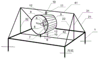
图1为本发明发电装置的结构示意图;Fig. 1 is the structural schematic diagram of the power generation device of the present invention;
图2为本发明发电装置的主视图;Fig. 2 is the front view of the power generation device of the present invention;
图3为本发明喇叭状导流罩的侧视图;Fig. 3 is the side view of the horn-shaped shroud of the present invention;
图4为本发明水轮机和机舱的结构示意图;Fig. 4 is the structural schematic diagram of the water turbine and the engine room of the present invention;
图5为本发明对水面罩壳的侧视放大图;Figure 5 is an enlarged side view of the water surface cover of the present invention;
图6为本发明对水面罩壳的俯视放大图;FIG. 6 is an enlarged plan view of the water surface cover of the present invention;
图7为本发明连接有滤网的安装底座示意图;Fig. 7 is the schematic diagram of the installation base connected with the filter screen according to the present invention;
图8为本发明滤网和旋转条的连接示意图;Fig. 8 is the connection schematic diagram of the filter screen and the rotating bar of the present invention;
图9为本发明旋转条的结构示意图。FIG. 9 is a schematic structural diagram of the rotating bar of the present invention.
附图标记说明:1固定桩柱;21斜撑杆Ⅰ;22斜撑杆Ⅱ;31立杆Ⅰ;32立杆Ⅱ;41横杆Ⅰ;42横杆Ⅱ;5喇叭状导流罩;51导流罩对水面;511对水面罩壳;512凹槽条;513转动板;52导流罩背水面;6转轮支架;7弧形叶片;8轮毂;9水平主轴;10连接轴;11流速流向感应器;12万向联轴器;13机舱;14增速器;15发电机;16控制器;17电气系统连接器;18滤网;19旋转条;191缠绕弹性绳;192圆柱杆。Description of reference numerals: 1 fixed pile; 21 diagonal strut I; 22 diagonal strut II; 31 vertical rod I; 32 vertical rod II; 41 crossbar I; 42 crossbar II; shroud to water surface; 511 to water surface cover; 512 groove strip; 513 rotating plate; 52 shroud back surface; 6 runner bracket; 7 arc blade; 8 hub; 9 horizontal main shaft; 10 connecting shaft; 11 Flow velocity sensor; 12 universal coupling; 13 engine room; 14 speed increaser; 15 generator; 16 controller; 17 electrical system connector; 18 filter; 19 rotating bar; 191 winding elastic rope; 192 cylindrical rod .
具体实施方式Detailed ways
以下结合附图和实施例作进一步详细描述:Describe in further detail below in conjunction with accompanying drawing and embodiment:
实施例1:Example 1:
如图1~4所示,一种可自动感应流向的坐底式水平轴潮流能发电装置,包括安装底座,安装底座固定在海底之上,安装底座上固定有喇叭状导流罩5,喇叭状导流罩5内部设有水轮机,水轮机后端连接有机舱13,喇叭状导流罩5上、下表面分别连接有万向联轴器12,万向联轴器12分别通过连接轴10连接于安装底座,喇叭状导流罩5的上表面连接的万向联轴器12和连接轴10之间还连接有流速流向感应器11。安装底座固定可靠性高,抗海水冲击能力强、抗干扰性能高。喇叭状导流罩5具有导流、聚能的作用,可以使通过水轮机的水流能量更加集中,增大潮流流速,从而提高水轮机的输出功率,提高潮流能的利用率,获得更多的电能,使水轮机具有较好的发电效益。水轮机和机舱13安装在喇叭状导流罩5内部,不仅可获得较好的发电效益,还可保护水轮机和机舱13,延长本装置的使用寿命。流速流向感应器11能及时捕捉潮流的流向变化,使喇叭状导流罩5的喇叭口能正对潮流流向,以便保证水轮机的叶片高速旋转,使水轮机始终处于高效率工作状态,提高对潮流能的利用率。万向联轴器12能使喇叭状导流罩5能自动适应潮流流向变化,根据潮流流向的变化而发生自由旋转,始终保持水轮机受到潮流的最大冲击,提高对潮流能的捕获利用。上述装置结构可靠性高,抗海浪冲击能力强,抗干扰性能高,结构简单、制造成本低,且可调整喇叭状导流罩5朝向,使水轮机始终能受到潮流的最大冲击,使水轮机始终处于高效率工作状态,提高对潮流能的利用率,使本装置具有较好的发电效益,且使用寿命长,维护成本低,对海洋环境无污染、干扰小。As shown in Figures 1 to 4, a bottom-mounted horizontal axis tidal current energy generation device that can automatically sense the flow direction includes an installation base, the installation base is fixed on the seabed, and a horn-shaped
喇叭状导流罩5采用喇叭形导流罩式结构,喇叭状导流罩5面向潮流一侧为圆形导流罩对水面51,喇叭状导流罩5另一侧为圆形导流罩背水面52,导流罩对水面51半径与导流罩背水面52半径比r1:r2优选为1:0.5。喇叭状导流罩式结构对潮流具有更好的聚能作用,导流罩对水面51与导流罩背水面52设有的半径比,使得喇叭状导流罩5在保证水轮机具有足够的旋转空间的情况下,能够增加喇叭状导流罩5对潮流的捕获截面,从而收集到更多的潮流能量,获得更多电能,提升发电效益。The horn-shaped
机舱13通过转轮支架6固定于喇叭状导流罩5内部,机舱13内部设有水平主轴9,水平主轴9一侧连接于水轮机,水平主轴9另一侧与增速器14连接,增速器14连接有控制器16和发电机15,发电机15连接有电气系统连接器17。水平主轴9将水轮机的机械能通过增速器14传递给发电机15。增速器14将转速较低的叶轮转化为高转速,从而提升发电机的工作效率。发电机15将潮流能转化的动能转化为交流电,实现绿色发电。电气系统连接器17将交流电输出至指定目标,实现发电机15发电后的电能采集与存储。The
水轮机包括轮毂8,轮毂8内部连接有水平旋转轴,水平旋转轴与机舱13连接,轮毂8表面连接有弧形叶片7,弧形叶片7从对水面向背水面凸起形成弧形,弧形叶片7与潮流方向垂直。弧形叶片7设有对水面和背水面,弧形叶片7从对水面向背水面凸起形成弧形,采用弧形叶片,可提升对水体流体的阻碍效果,增加叶轮的旋转动力,使本装置在低速潮流下依然具有良好的自启动性能,进一步提高本装置的发电效率。The water turbine includes a
安装底座包括四根垂直设置的固定桩柱1,固定桩柱1底部打入海底,固定桩柱1之间通过连杆两两连接形成矩形,矩形一侧中心连接有立杆Ⅰ31,矩形另一侧中心连接有立杆Ⅱ32,立杆Ⅰ31和立杆Ⅱ32由斜撑杆Ⅰ21和斜撑杆Ⅱ22支撑,立杆Ⅰ31和立杆Ⅱ32顶部和底部分别连接有横杆Ⅰ41和横杆Ⅱ42,立杆Ⅰ31和立杆Ⅱ32之间距离与喇叭状导流罩5长度比优选为1:1.7。上述安装底座采用三角形形状搭建,使得安装底座具有稳固的结构,能够抵抗潮流对安装底座的冲击,避免潮流冲击带来的环境因素干扰,且立杆Ⅰ31和立杆Ⅱ32之间距离与喇叭状导流罩5长度设有的比例,可保证喇叭状导流罩5能够随着潮流流向的改变而旋转至最佳流向位置上,使得装置在潮流流向发生变化时仍能保持转动发电且具有较高的工作效率。The installation base includes four vertically arranged
一种可自动感应流向的坐底式水平轴潮流能发电原理,发电原理为:采用流速流向感应器11辨别潮流方向,通过万向联轴器12将喇叭状导流罩5调节至面向潮流方向,潮流驱动水轮机转动,水轮机通过增速器14增速后驱动发电机15工作,发电机15通过电气系统连接器17输出交流电,完成潮流能发电。上述发电原理通过流速流向感应器11和万向联轴器12达到自适应潮流流向功能,使得本装置在潮流流向发生变化时仍能保持转动发电,提高对潮流的利用率,提升本装置的发电效率。A bottom-mounted horizontal axis tidal current power generation principle that can automatically sense the flow direction. The power generation principle is as follows: the
本实施例中的常规技术为本领域技术人员所知晓的现有技术,在此不作详细叙述。The conventional technology in this embodiment is the prior art known to those skilled in the art, and will not be described in detail here.
实施例2:Example 2:
如图3、5、6所示,本实施例为在实施例1的基础上,对喇叭状导流罩5的进一步优化方案为:喇叭状导流罩5的导流罩对水面51一侧壳体为对水面罩壳511,对水面罩壳511为弧状,对水面罩壳511内壁设有凹槽条512,凹槽条512内部均布有转动板513,转动板513通过连杆可旋转式固接于凹槽条512内壁。凹槽条512的设计提升了喇叭状导流罩5在弧状对水面罩壳511处的潮流导流作用,降低潮水对喇叭状导流罩5的正面冲击力,同时提升了潮水捕获能力,提升发电效益。且均布于凹槽条512内部的转动板513为可旋转式连接,在潮水的冲击下,转动板513转动,从而改变对水面罩壳511内壁附近的潮水分布,均匀潮水内部受力情况,避免进入喇叭状导流罩5的潮流因水面罩壳511的截面变化而产生压强差使潮流边界层分离从而产生漩涡,降低了潮流的能量损失,提高发电效益,还可提升潮流流动顺畅性,避免潮流产生漩涡影响潮流流动,提升本装置对潮流的利用率和装置运行的可靠性。As shown in FIGS. 3 , 5 and 6 , this embodiment is based on
本实施例中的常规技术为本领域技术人员所知晓的现有技术,在此不作详细叙述。The conventional technology in this embodiment is the prior art known to those skilled in the art, and will not be described in detail here.
实施例3:Example 3:
如图7~9所示:本实施例为在实施例1的基础上,对安装底座的进一步优化方案为:安装底座外表面均连接有滤网18,滤网18的网格的相对边连接有旋转条19,滤网18表面以四格网格长度为半径形成的圆所涉及的网格中有且仅有一个旋转条19,旋转条19包括一根缠绕弹性绳191,缠绕弹性绳191缠绕转折处穿接有圆柱杆192。滤网18的设置可有效防止潮水中杂质对水轮机工作的影响,提高装置工作可靠性。旋转条19连接在以四格网格长度为半径形成的圆的圆心处的网格上,此设置可有效避免旋转条19之间发生缠绕,提高旋转条19工作可靠性,滤网18在潮水冲击下会发生伸缩,使得连接在网格相对边的缠绕弹性绳191因拉伸和收缩发生转动,带动圆柱杆192发生快速转动,转动中的192可抵挡随潮流而冲向本装置的硬物杂质对装置的损伤,也可对潮流中软物杂质进行缠绕避免影响水轮机的正常工作,可有效提高本装置的工作可靠性,延长使用寿命,且快速转动的圆柱杆192带动周围潮流水体发生转动,改变进入滤网18时的水流流动方向和流速分布变化,使潮流水体集中从滤网18网格中通过,避免滤网18的网格线对潮流产生能量损耗,且多股从滤网18网格中通过的水流在滤网18内部汇合,由连续性方程
缠绕弹性绳191由多股复合弹性纤维纠缠制得,复合弹性纤维的优选制备方法为:按重量份计,取聚烯烃弹性体母粒45份、热塑性树脂39份、硅橡胶8份、辐照敏感剂0.6份和抗氧化剂8份混合,送入双螺杆挤出机,在185℃下挤出切粒制得聚烯烃混合母粒;将聚烯烃混合母粒送入熔融纺丝机料斗,再加入1.12份2,8一二叔丁基-4一甲基苯酚和0.02份1-氨基-2-羟甲基二氢吲哚,控制温度为200℃,由喷丝头喷出,经过侧吹风甬道冷却,经卷绕装置卷绕到筒子上,得到初生复合弹性纤维;将所制得的初生复合弹性纤维置于辐照环境下处理,在550kGy的辐照敏感剂量下,制得复合弹性纤维。辐照敏感剂为三烯丙基异氰脲酸酯,抗氧化剂为市场上常规购买,上述制得的复合弹性纤维具有良好的回弹性以及抗断裂强度,加入的1-氨基-2-羟甲基二氢吲哚中(S)-1-氨基-2-羟甲基二氢吲哚与(R)-1-氨基-2-羟甲基二氢吲哚的重量份比为1:0.06,具有特殊配比的1-氨基-2-羟甲基二氢吲哚与2,8一二叔丁基-4一甲基苯酚具有协同作用,可有效降低聚烯烃弹性体母粒和热塑性树脂的交联温度,使纤维分子产生更多的共价交联点,从而使纤维分子能够形成稳固的三维网络结构,提高复合弹性纤维的弹性和回弹性,由上述制备方法所得的复合弹性纤维纠缠形成缠绕弹性绳191,所得的缠绕弹性绳191的弹性好、抗断裂强度高,不仅可有效延长缠绕弹性绳191的工作可靠性以及提升缠绕弹性绳191,使圆柱杆192产生高速旋转,避免杂质对装置工作的影响,有效提高进入滤网18的潮流流速,提升发电效益,上述产生的协同作用还可提高纤维分子之间交联的紧密形,有效避免海水中海生生物的附着而影响缠绕弹性绳191缠绕杂质和旋转的性能,提升缠绕弹性绳191的自清洁能力和抗干扰能力。The wound
本实施例中的常规技术为本领域技术人员所知晓的现有技术,在此不作详细叙述。The conventional technology in this embodiment is the prior art known to those skilled in the art, and will not be described in detail here.
实施例4:Example 4:
如图1~9所示,本发明装置的结构连接为:四根固定桩柱1固定于海底,四根固定桩柱1之间通过连杆两两连接形成矩形,矩形的一对相对的两条边的中心连接有立杆Ⅰ31和立杆Ⅱ32,矩形的四个角分别连接有斜撑杆Ⅰ21和斜撑杆Ⅱ22,与立杆同侧的斜撑杆顶部和立杆顶部相连接,立杆Ⅰ31和立杆Ⅱ32底部之间连接有横杆Ⅱ42,立杆Ⅰ31和立杆Ⅱ32顶部之间连接有横杆Ⅰ41,固定桩柱1形成的矩形、斜撑杆之间形成的面均连接有滤网18,滤网18围绕形成横向三棱柱形;喇叭状导流罩5上表面连接有万向联轴器12,万向联轴器12连接有流速流向感应器11,流速流向感应器11连接有连接轴10,连接轴10固定于横杆Ⅰ41中心,喇叭状导流罩5下表面连接有万向联轴器12,万向联轴器12连接有连接轴10,连接轴10固定于横杆Ⅱ42中心;喇叭状导流罩5内部近导流罩背水面51处通过转轮支架6设有机舱13,机舱13内部设有水平主轴9,水平主轴9一侧连接于水轮机,水平主轴9另一侧与增速器14连接,增速器14与控制器16和发电机15连接,发电机15通过连接的电气系统连接器17输出交流电;机舱13前端连接有水轮机,水轮机包括轮毂8,轮毂8内部连接有水平旋转轴,水平旋转轴与机舱13内部的水平主轴9连接,轮毂8表面连接有3片弧形叶片7。As shown in Figures 1 to 9, the structure of the device of the present invention is connected as follows: four fixed
在上述结构连接的基础上,本发明的发电原理为:流速流向感应器11辨别潮流方向,通过万向联轴器12将喇叭状导流罩5调节至面向潮流方向,使喇叭状导流罩5始终朝向潮流方向,进而能得到最大的潮流能,潮流驱动水轮机的弧形叶片7转动,水轮机形成的机械能通过增速器14增速后驱动发电机15工作,发电机15发电后通过电气系统连接器17输出交流电,完成潮流能发电。On the basis of the above-mentioned structural connection, the power generation principle of the present invention is as follows: the
本实施例中的常规技术为本领域技术人员所知晓的现有技术,在此不作详细叙述。The conventional technology in this embodiment is the prior art known to those skilled in the art, and will not be described in detail here.
以上实施方式仅用于说明本发明,而并非对本发明的限制,本领域的普通技术人员,在不脱离本发明的精神和范围的情况下,还可以做出各种变化和变型。因此,所有等同的技术方案也属于本发明的范畴,本发明的专利保护范围应由权利要求限定。The above embodiments are only used to illustrate the present invention, but not to limit the present invention. Those skilled in the art can also make various changes and modifications without departing from the spirit and scope of the present invention. Therefore, all equivalent technical solutions also belong to the scope of the present invention, and the patent protection scope of the present invention should be defined by the claims.
Claims (4)
Priority Applications (1)
| Application Number | Priority Date | Filing Date | Title |
|---|---|---|---|
| CN201711343323.0A CN108131237B (en) | 2017-12-14 | 2017-12-14 | Bottom-sitting type horizontal shaft tidal current energy power generation principle and device capable of automatically sensing flow direction |
Applications Claiming Priority (1)
| Application Number | Priority Date | Filing Date | Title |
|---|---|---|---|
| CN201711343323.0A CN108131237B (en) | 2017-12-14 | 2017-12-14 | Bottom-sitting type horizontal shaft tidal current energy power generation principle and device capable of automatically sensing flow direction |
Publications (2)
| Publication Number | Publication Date |
|---|---|
| CN108131237A CN108131237A (en) | 2018-06-08 |
| CN108131237B true CN108131237B (en) | 2020-08-04 |
Family
ID=62390179
Family Applications (1)
| Application Number | Title | Priority Date | Filing Date |
|---|---|---|---|
| CN201711343323.0A Active CN108131237B (en) | 2017-12-14 | 2017-12-14 | Bottom-sitting type horizontal shaft tidal current energy power generation principle and device capable of automatically sensing flow direction |
Country Status (1)
| Country | Link |
|---|---|
| CN (1) | CN108131237B (en) |
Families Citing this family (6)
| Publication number | Priority date | Publication date | Assignee | Title |
|---|---|---|---|---|
| CN109185035B (en) * | 2018-10-31 | 2020-04-03 | 宁波大学 | Self-balancing tidal current energy power generation device |
| CN111706457B (en) * | 2020-07-21 | 2024-04-26 | 上海海洋大学 | Ocean power generation device combined with offshore wind turbine |
| CN112647473A (en) * | 2020-10-09 | 2021-04-13 | 曹青姣 | Tidal power generation tidal gate with self-cleaning function |
| CN112761846A (en) * | 2020-12-31 | 2021-05-07 | 潍坊新力蒙水产技术有限公司 | Longitudinal sinking split type axial flow power generation device |
| CN115750213A (en) * | 2022-12-02 | 2023-03-07 | 广东海洋大学 | Offshore power generation platform with wind energy and ocean current energy complementation |
| CN118745963A (en) * | 2024-06-20 | 2024-10-08 | 哈尔滨工程大学三亚南海创新发展基地 | A fixed horizontal axis water flow power generation device |
Family Cites Families (6)
| Publication number | Priority date | Publication date | Assignee | Title |
|---|---|---|---|---|
| CA2649828A1 (en) * | 2006-04-28 | 2007-11-08 | Swanturbines Limited | Tidal current turbine |
| CN102066667B (en) * | 2008-04-14 | 2014-09-17 | 亚特兰蒂斯能源有限公司 | central axis hydraulic turbine |
| CA2643567A1 (en) * | 2008-11-10 | 2010-05-10 | Organoworld Inc. | Fluid directing system for turbines |
| CN101994637B (en) * | 2010-11-23 | 2012-12-19 | 哈尔滨工程大学 | Base type tide power generator |
| CN201891547U (en) * | 2010-12-06 | 2011-07-06 | 中国海洋大学 | Axial flow paddle type water turbine |
| CN104389729B (en) * | 2014-10-11 | 2016-09-14 | 浙江大学 | A kind of ocean bottom currents generating and electrical energy storage system |
-
2017
- 2017-12-14 CN CN201711343323.0A patent/CN108131237B/en active Active
Also Published As
| Publication number | Publication date |
|---|---|
| CN108131237A (en) | 2018-06-08 |
Similar Documents
| Publication | Publication Date | Title |
|---|---|---|
| CN108131237A (en) | It is a kind of can automatic sensing flow direction bottom-sitting type horizontal axis tidal current energy electricity generating principle and device | |
| CN103266982B (en) | A kind of wave power conversion Pneumatic electric generating method and apparatus | |
| CN110184993A (en) | A kind of square-box-shaped floating breakwater with oscillaton water column type wave energy generating set | |
| US20100327594A1 (en) | Complex ocean power system combining sluice power and ocean current power | |
| CN103216375B (en) | A kind of bulb through-flow turbine for micro-water head power station | |
| WO2017000555A1 (en) | Modular two-way power generation device using tidal energy | |
| CN103321825A (en) | Tidal current energy capturing water turbine with changeable blade gestures | |
| CN201396237Y (en) | Twin-linkage marine current turbine | |
| WO2020010872A1 (en) | Ultralow-head hydroelectric generator | |
| CN112124507A (en) | Wind energy wave photovoltaic power generation floating platform and using method thereof | |
| CN202348548U (en) | Tide current power generation device and tide current generator set | |
| CN202266366U (en) | Horizontal shaft variable blade pitch tidal current energy water turbine | |
| CN103953495B (en) | Collecting type self adaption electric generating apparatus using tidal current | |
| CN102748201A (en) | Pod type tidal generator set | |
| CN209741790U (en) | Comb-type breakwater integrating wave energy and tidal current energy power generation device | |
| CN111425328A (en) | Wind-water rotating wheel and ocean energy comprehensive power generation device thereof | |
| CN102943730B (en) | A wave force direct drive water turbine | |
| CN111706457A (en) | An ocean energy power generation device combined with an offshore wind turbine | |
| CN103644067A (en) | Spiral-vane vertical-shaft tide water turbine | |
| CN220581175U (en) | Sail type vertical axis wind power generation device | |
| CN2484415Y (en) | Water-wind power generator impeller | |
| CN102808737B (en) | Drag type narrow tube wind gathering power generation system | |
| CN201953552U (en) | Wave-gathering bidirectional water/wind power generation device | |
| CN206668454U (en) | A kind of Wave power generation device | |
| CN116557198A (en) | A pumped storage wind wave power generation equipment |
Legal Events
| Date | Code | Title | Description |
|---|---|---|---|
| PB01 | Publication | ||
| PB01 | Publication | ||
| SE01 | Entry into force of request for substantive examination | ||
| SE01 | Entry into force of request for substantive examination | ||
| GR01 | Patent grant | ||
| GR01 | Patent grant |