CN108168221B - A vacuum freeze-drying device and a method for vacuum freeze-drying materials - Google Patents
A vacuum freeze-drying device and a method for vacuum freeze-drying materials Download PDFInfo
- Publication number
- CN108168221B CN108168221B CN201810102474.5A CN201810102474A CN108168221B CN 108168221 B CN108168221 B CN 108168221B CN 201810102474 A CN201810102474 A CN 201810102474A CN 108168221 B CN108168221 B CN 108168221B
- Authority
- CN
- China
- Prior art keywords
- refrigerant
- layer
- heat medium
- coil
- vacuum
- Prior art date
- Legal status (The legal status is an assumption and is not a legal conclusion. Google has not performed a legal analysis and makes no representation as to the accuracy of the status listed.)
- Active
Links
Images


Classifications
-
- F—MECHANICAL ENGINEERING; LIGHTING; HEATING; WEAPONS; BLASTING
- F26—DRYING
- F26B—DRYING SOLID MATERIALS OR OBJECTS BY REMOVING LIQUID THEREFROM
- F26B5/00—Drying solid materials or objects by processes not involving the application of heat
- F26B5/04—Drying solid materials or objects by processes not involving the application of heat by evaporation or sublimation of moisture under reduced pressure, e.g. in a vacuum
- F26B5/06—Drying solid materials or objects by processes not involving the application of heat by evaporation or sublimation of moisture under reduced pressure, e.g. in a vacuum the process involving freezing
-
- Y—GENERAL TAGGING OF NEW TECHNOLOGICAL DEVELOPMENTS; GENERAL TAGGING OF CROSS-SECTIONAL TECHNOLOGIES SPANNING OVER SEVERAL SECTIONS OF THE IPC; TECHNICAL SUBJECTS COVERED BY FORMER USPC CROSS-REFERENCE ART COLLECTIONS [XRACs] AND DIGESTS
- Y02—TECHNOLOGIES OR APPLICATIONS FOR MITIGATION OR ADAPTATION AGAINST CLIMATE CHANGE
- Y02P—CLIMATE CHANGE MITIGATION TECHNOLOGIES IN THE PRODUCTION OR PROCESSING OF GOODS
- Y02P70/00—Climate change mitigation technologies in the production process for final industrial or consumer products
- Y02P70/10—Greenhouse gas [GHG] capture, material saving, heat recovery or other energy efficient measures, e.g. motor control, characterised by manufacturing processes, e.g. for rolling metal or metal working
Landscapes
- Engineering & Computer Science (AREA)
- Health & Medical Sciences (AREA)
- Life Sciences & Earth Sciences (AREA)
- Molecular Biology (AREA)
- Mechanical Engineering (AREA)
- General Engineering & Computer Science (AREA)
- Drying Of Solid Materials (AREA)
Abstract
本发明涉及真空冷冻干燥技术领域,尤其涉及一种真空冷冻干燥装置及利用上述真空冷冻干燥装置进行真空冷冻干燥物料的方法。真空冷冻干燥装置包括真空箱,真空箱内设有隔板支架、冷媒进汇总管、冷媒出汇总管、热媒进汇总管、热媒出汇总管、不少于一层的热交换层,热交换层包括单层热媒盘管、单层冷媒盘管、单层面板,单层热媒盘管与单层冷媒盘管并排设置并呈S形排布,单层热媒盘管与单层冷媒盘管贴合固定在单层面板的一侧。本发明中的冷媒和热媒各自走不同的管路,以方便多个冷冻真空干燥仓即便在不同的工艺节点也可以利用公共的冷媒和热媒,同时当制冷和制热切换时,冷媒或热媒可以通过各自盘管回收至总的冷媒储罐或热媒储罐中以节省能源。
The invention relates to the technical field of vacuum freeze-drying, in particular to a vacuum freeze-drying device and a method for vacuum freeze-drying materials using the vacuum freeze-drying device. The vacuum freeze-drying device includes a vacuum box, which is provided with a partition bracket, a refrigerant inlet and collection pipe, a refrigerant outlet collection pipe, a heat medium inlet collection pipe, a heat medium outlet collection pipe, and no less than one heat exchange layer. The exchange layer includes a single-layer heat medium coil, a single-layer refrigerant coil, and a single-layer panel. The single-layer heat The refrigerant coil is fitted and fixed on one side of the single-layer panel. The refrigerant and heat medium in the present invention go through different pipelines, so that multiple freezer vacuum drying chambers can use common refrigerant and heat medium even at different process nodes. At the same time, when cooling and heating are switched, the refrigerant or The heat medium can be recycled to the general refrigerant storage tank or heat medium storage tank through the respective coils to save energy.
Description
技术领域technical field
本发明涉及真空冷冻干燥技术领域,尤其涉及一种真空冷冻干燥装置。本发明还涉及一种利用上述真空冷冻干燥装置进行真空冷冻干燥物料的方法。The invention relates to the technical field of vacuum freeze-drying, in particular to a vacuum freeze-drying device. The present invention also relates to a method for vacuum freeze-drying materials by using the vacuum freeze-drying device.
背景技术Background technique
真空冷冻干燥,也称升华干燥,其原理是将物料冷冻,使其含有的水份变成冰块,然后在真空下使冰块升华而达到干燥目的。因此可知,真空冷冻干燥的完成,除了需要一定的真空度以外,还需要在不同的时间节点控制物料的温度。Vacuum freeze-drying, also known as sublimation drying, is based on the principle of freezing the material to turn the water contained in it into ice cubes, and then sublimating the ice cubes under vacuum to achieve the purpose of drying. Therefore, it can be seen that in addition to a certain degree of vacuum, the completion of vacuum freeze-drying also needs to control the temperature of the material at different time points.
目前,真空冷冻干燥箱内部通常采用单回路盘管结构,其内部只能流动单一媒介(如硅油、导热油),该媒介按照工艺要求需要通过换热器变冷或者变热来控制温度,这样的媒介以及后续的操作中通常会出现以下缺点。At present, the interior of the vacuum freeze-drying box usually adopts a single-circuit coil structure, and only a single medium (such as silicone oil, heat transfer oil) can flow inside, and the temperature of the medium needs to be cooled or heated by the heat exchanger according to the process requirements, so that The following disadvantages usually occur in the medium and subsequent operation.
同一媒介需要反复的变温,能耗偏高,降低媒介品质;媒介选择性很小,常常使用硅油或导热油,这一类媒介比容热比较小,只有水的40%或者更低;硅油或导热油表面张力小,易从机器中泄漏;硅油或导热油热膨胀系数较大,容易产生超压问题;硅油或导热油润滑性欠佳,流动阻力较大;硅油或导热油有一定的吸湿性,吸湿后,凝固点降低;硅油或导热油价格相对较贵。The same medium needs to change temperature repeatedly, the energy consumption is high, and the quality of the medium is reduced; the selectivity of the medium is very small, and silicone oil or heat transfer oil is often used. The specific heat of this type of medium is relatively small, only 40% or lower of water; silicone oil or Heat transfer oil has a small surface tension and is easy to leak from the machine; silicone oil or heat transfer oil has a large thermal expansion coefficient, which is prone to overpressure problems; silicone oil or heat transfer oil has poor lubricity and large flow resistance; silicone oil or heat transfer oil has certain hygroscopicity , After moisture absorption, the freezing point is lowered; the price of silicone oil or heat transfer oil is relatively expensive.
因此,如何解决由于采用单一媒介进行真空冷冻物料所造成的上述问题,成为本领域技术人员亟待解决的技术难题。Therefore, how to solve the above-mentioned problems caused by using a single medium for vacuum freezing materials has become a technical problem to be solved urgently by those skilled in the art.
发明内容Contents of the invention
本发明的第一个目的是提供一种真空冷冻干燥装置,以解决由于采用单一媒介进行真空冷冻干燥物料所产生的问题。The first object of the present invention is to provide a vacuum freeze-drying device to solve the problems caused by using a single medium for vacuum freeze-drying materials.
本发明的第二个目的是提供一种利用上述真空冷冻干燥装置进行真空冷冻干燥物料的方法。The second object of the present invention is to provide a method for vacuum freeze-drying materials using the above-mentioned vacuum freeze-drying device.
为了实现上述第一个目的,本发明提供了一种真空冷冻干燥装置,包括真空箱,所述真空箱内设有隔板支架、冷媒进汇总管、冷媒出汇总管、热媒进汇总管、热媒出汇总管、不少于一层的热交换层,所述热交换层包括单层热媒盘管、单层冷媒盘管、单层面板,所述单层热媒盘管与所述单层冷媒盘管并排设置并呈S形排布,所述单层热媒盘管与所述单层冷媒盘管贴合固定在所述单层面板的一侧,所述单层面板固定在所述隔板支架上;所述单层热媒盘管的热媒进口、热媒出口分别连通所述热媒进汇总管、所述热媒出汇总管,所述单层冷媒盘管的冷媒进口、冷媒出口分别连通所述冷媒进汇总管、所述冷媒出汇总管。In order to achieve the above-mentioned first object, the present invention provides a vacuum freeze-drying device, comprising a vacuum box, the vacuum box is provided with a partition support, a refrigerant inlet and collection pipe, a refrigerant outlet collection pipe, a heat medium inlet collection pipe, Heat medium outlet collecting pipe, no less than one heat exchange layer, the heat exchange layer includes single-layer heat medium coil, single-layer refrigerant coil, single-layer panel, the single-layer heat medium coil and the The single-layer refrigerant coils are arranged side by side and arranged in an S shape, and the single-layer heat medium coils are attached to the single-layer refrigerant coils and fixed on one side of the single-layer panel, and the single-layer panel is fixed on On the partition bracket; the heat medium inlet and the heat medium outlet of the single-layer heat medium coil are respectively connected to the heat medium inlet and outlet manifolds, and the refrigerant of the single-layer refrigerant coil The inlet and the refrigerant outlet are respectively connected to the refrigerant inlet collecting pipe and the refrigerant outlet collecting pipe.
优选的,所述单层热媒盘管的热媒进口、热媒出口分别通过弯管连通所述热媒进汇总管、所述热媒出汇总管;所述单层冷媒盘管的冷媒进口、冷媒出口分别通过弯管连通所述冷媒进汇总管、所述冷媒出汇总管。Preferably, the heat medium inlet and the heat medium outlet of the single-layer heat medium coil are respectively connected to the heat medium inlet collecting pipe and the heat medium outlet collecting pipe through elbows; the refrigerant inlet of the single-layer refrigerant coil The refrigerant outlet and the refrigerant outlet are respectively connected to the refrigerant inlet collecting pipe and the refrigerant outlet collecting pipe through an elbow.
优选的,所述单层热媒盘管的热媒进口、所述单层冷媒盘管的冷媒进口在竖直方向低于所述单层面板,所述单层热媒盘管的热媒出口、所述单层冷媒盘管的冷媒出口在竖直方向高于所述单层面板。Preferably, the heat medium inlet of the single-layer heat medium coil and the refrigerant inlet of the single-layer refrigerant coil are vertically lower than the single-layer panel, and the heat medium outlet of the single-layer heat medium coil . The refrigerant outlet of the single-layer refrigerant coil is vertically higher than the single-layer panel.
优选的,所述热媒进汇总管、所述热媒出汇总管、所述冷媒进汇总管、所述冷媒出汇总管均通过弯头水平延伸至所述真空箱体外。Preferably, the heat medium inlet header, the heat medium outlet header, the refrigerant inlet header, and the refrigerant outlet header all extend horizontally to the outside of the vacuum box through elbows.
优选的,所述热媒进汇总管的进口位置在竖直方向低于所述热媒出汇总管的出口位置,所述冷媒进汇总管的进口位置在竖直方向低于所述冷媒出汇总管的出口位置。Preferably, the inlet position of the heat medium inlet collecting pipe is lower than the outlet position of the heat medium outlet collecting pipe in the vertical direction, and the inlet position of the refrigerant inlet collecting pipe is lower than the outlet position of the refrigerant outlet collecting pipe in the vertical direction. The outlet position of the tube.
优选的,所述真空箱包括真空箱体和真空门,所述真空箱体与所述真空门通过双铰链结构连接。Preferably, the vacuum box includes a vacuum box and a vacuum door, and the vacuum box and the vacuum door are connected by a double hinge structure.
优选的,所述真空箱体上设有一个人孔和不少于一个的真空抽气管道。Preferably, the vacuum box is provided with a manhole and no less than one vacuum suction pipe.
优选的,所述真空箱体和所述真空门均包括内板和加强矩形管,所述加强矩形管固定在所述内板上,所述真空箱体和所述真空门的外侧均覆盖有保温层。Preferably, both the vacuum box and the vacuum door include an inner plate and a reinforced rectangular tube, the reinforced rectangular tube is fixed on the inner plate, and the outside of the vacuum box and the vacuum door are covered with Insulation.
优选的,所述热媒为热水,所述冷媒为氯化钙盐水。Preferably, the heating medium is hot water, and the cooling medium is calcium chloride brine.
为了实现上述第二个目的,本发明提供了一种利用上述的真空冷冻干燥装置进行真空冷冻干燥物料的方法,包括:In order to achieve the above-mentioned second purpose, the present invention provides a method for vacuum freeze-drying materials using the above-mentioned vacuum freeze-drying device, including:
将待干燥物料放于所述单层面板上;Put the material to be dried on the single-layer board;
通过所述冷媒进汇总管向所述单层冷媒盘管内注入冷媒,所述冷媒经所述单层冷媒盘管进入冷媒出汇总管,待干燥物料的温度达到预设冻结温度后,反向泵出所述单层冷媒盘管内的冷媒;Inject refrigerant into the single-layer refrigerant coil through the refrigerant inlet and collection pipe, and the refrigerant enters the refrigerant outlet collection pipe through the single-layer refrigerant coil. After the temperature of the dry material reaches the preset freezing temperature, the reverse pump discharge the refrigerant in the single-layer refrigerant coil;
对所述真空箱进行抽真空,使得所述真空箱内的真空度达到预设值;vacuumizing the vacuum box so that the vacuum degree in the vacuum box reaches a preset value;
通过热媒进汇总管向所述单层热媒盘管内注入热媒,所述热媒经所述单层热媒盘管进入热媒出汇总管,控制所述热媒的流量,使得待干燥物料的温度按预设温度时间变化曲线进行变化;Heat medium is injected into the single-layer heat medium coil through the heat medium inlet and collection pipe, and the heat medium enters the heat medium out of the heat medium coil through the single-layer heat medium coil to control the flow of the heat medium so that the drying The temperature of the material changes according to the preset temperature time change curve;
待干燥物料干燥完毕后,反向泵出所述单层热媒盘管内的热媒;After the drying material is dried, reversely pump out the heat medium in the single-layer heat medium coil;
通过所述冷媒进汇总管向所述单层冷媒盘管内注入冷媒,所述冷媒经所述单层冷媒盘管进入冷媒出汇总管,待干燥物料的温度冷却到预设冷却温度后,反向泵出所述单层冷媒盘管内的冷媒;Inject refrigerant into the single-layer refrigerant coil through the refrigerant inlet and collection pipe, and the refrigerant enters the refrigerant outlet collection pipe through the single-layer refrigerant coil. After the temperature of the dry material cools to the preset cooling temperature, reverse Pump out the refrigerant in the single-layer refrigerant coil;
使得所述真空箱内的真空度恢复至常压,取出干燥后的物料。The vacuum in the vacuum box is returned to normal pressure, and the dried material is taken out.
本发明提供的真空冷冻干燥装置及真空冷冻干燥物料的方法,采用热媒循环回路和冷媒循环回路并排设计的方案,使得真空干燥装置具有制冷和制热功能,让冷媒和热媒各自在不同的回路里进行热交换,不需要对冷媒或热媒进行变温,冷媒和热媒选择的空间比较大,多个真空冷冻干燥装置即便在不同的工艺节点,也可以利用公共的冷媒和热媒;当制冷或制热切换时,冷媒和热媒可以通过各种的盘管回收至冷媒储罐或热媒储罐内,达到节省能源的目的。The vacuum freeze-drying device and the method for vacuum freeze-drying materials provided by the present invention adopt the scheme of side-by-side design of the heat medium circulation circuit and the refrigerant circulation circuit, so that the vacuum drying device has the functions of cooling and heating, so that the refrigerant and heat medium are respectively in different The heat exchange in the circuit does not need to change the temperature of the refrigerant or heat medium. The choice of refrigerant and heat medium is relatively large. Even if multiple vacuum freeze-drying devices are in different process nodes, they can also use common refrigerant and heat medium; When cooling or heating is switched, the refrigerant and heat medium can be recycled to the refrigerant storage tank or heat medium storage tank through various coils to save energy.
附图说明Description of drawings
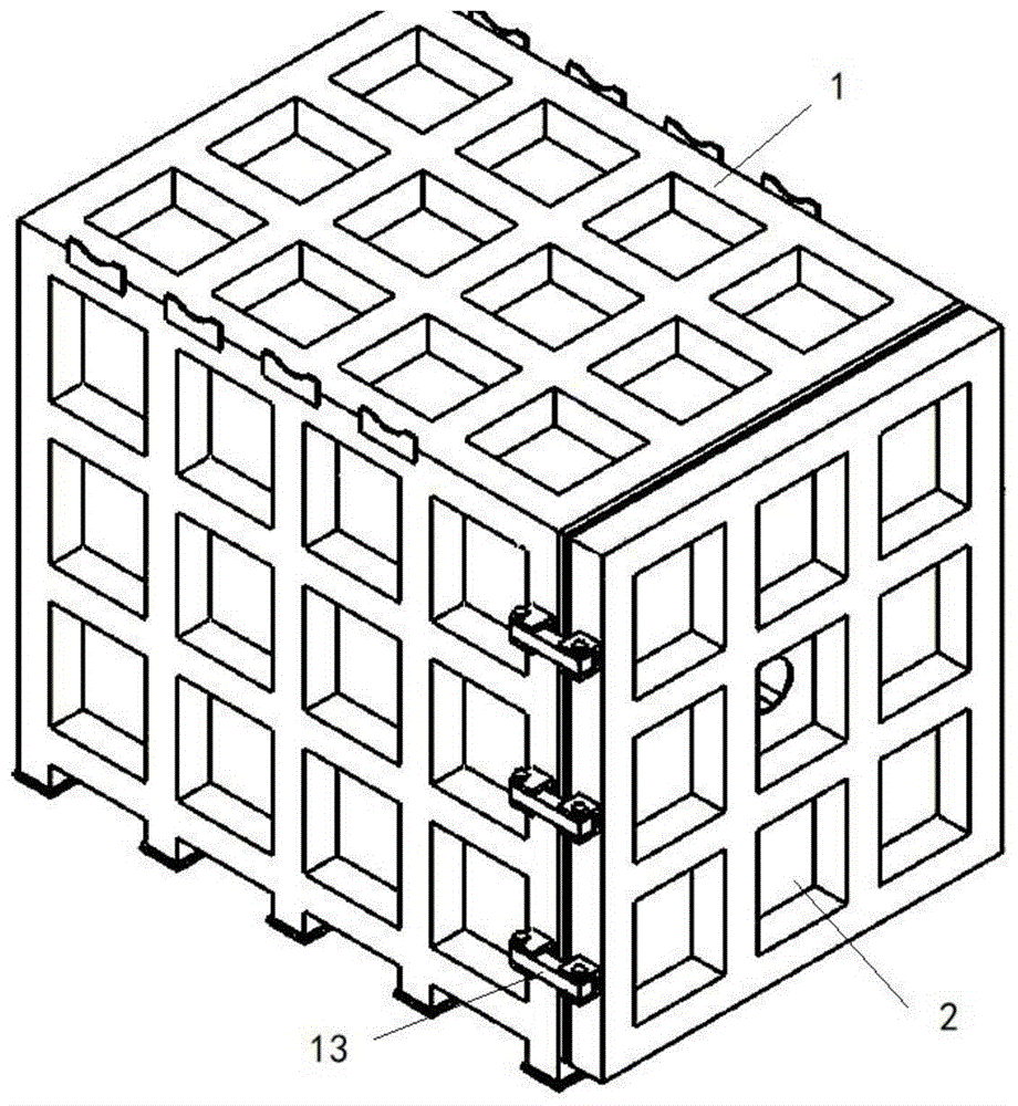
图1为本发明一种实施例提供的真空冷冻干燥装置的正面立体结构示意图;Fig. 1 is a schematic diagram of the front stereoscopic structure of a vacuum freeze-drying device provided by an embodiment of the present invention;
图2为图1中真空冷冻干燥装置的背面立体结构示意图;Fig. 2 is the schematic diagram of the rear stereoscopic structure of the vacuum freeze-drying device in Fig. 1;
图3为图1中隔板支架的结构示意图;Fig. 3 is the structural schematic diagram of partition support in Fig. 1;
图4为图1中热交换层与热媒进汇总管、冷媒进汇总管、热媒出汇总管、冷媒出汇总管连接的结构示意图;Fig. 4 is a schematic diagram of the structure of the connection between the heat exchange layer and the heat medium inlet collecting pipe, the refrigerant inlet collecting pipe, the heat medium outlet collecting pipe, and the refrigerant outlet collecting pipe in Fig. 1;
图5为图1中单层热交换层的结构示意图;Fig. 5 is a schematic structural view of the single-layer heat exchange layer in Fig. 1;
图6为多个真空冷冻干燥装置工作状态分布结构示意图;Fig. 6 is a schematic diagram of the working state distribution structure of multiple vacuum freeze-drying devices;
其中,图1-图6中:Among them, in Fig. 1-Fig. 6:
真空箱体1、真空门2、热交换层3、真空抽气管道4、单层热媒盘管5、单层冷媒盘管6、单层面板7、热媒进汇总管8、热媒出汇总管9、冷媒进汇总管10、冷媒出汇总管11、隔板支架12、双铰链结构13、人孔14、弯管15、弯管16;
真空冷冻干燥装置100、共用制热机200、共用制冷机300、共用真空泵400、共用冷媒管道500、共用热媒管道600、共用真空管道700。Vacuum freeze-
具体实施方式Detailed ways
为了使本领域的技术人员更好地理解本发明的技术方案,下面将结合附图对本发明作进一步的详细介绍。In order to enable those skilled in the art to better understand the technical solutions of the present invention, the present invention will be further described in detail below in conjunction with the accompanying drawings.
请参看图1-图5,图1为本发明一种实施例提供的真空冷冻干燥装置的正面立体结构示意图;图2为图1中真空冷冻干燥装置的背面立体结构示意图;图3为图1中隔板支架的结构示意图;图4为图1中热交换层与热媒进汇总管、冷媒进汇总管、热媒出汇总管、冷媒出汇总管连接的结构示意图;图5为图1中单层热交换层的结构示意图。Please refer to Fig. 1-Fig. 5, Fig. 1 is the front three-dimensional structure schematic diagram of the vacuum freeze-drying device provided by an embodiment of the present invention; Fig. 2 is the back stereoscopic structure schematic diagram of the vacuum freeze-drying device in Fig. 1; Fig. 3 is Fig. 1 Schematic diagram of the structure of the middle partition bracket; Figure 4 is a schematic diagram of the connection between the heat exchange layer in Figure 1 and the heat medium inlet header, refrigerant inlet header, heat medium outlet header, and refrigerant outlet header; Schematic diagram of the structure of a single-layer heat exchange layer.
如图1-图5所示,本发明提供的真空冷冻干燥装置,包括真空箱,所述真空箱可以呈正方体或者长方体或者其他形状;所述真空箱内设有隔板支架12、冷媒进汇总管10、冷媒出汇总管11、热媒进汇总管8、热媒出汇总管9、不少于一层的热交换层3。As shown in Figures 1-5, the vacuum freeze-drying device provided by the present invention includes a vacuum box, and the vacuum box can be a cube or a cuboid or other shapes; Pipe 10, refrigerant
所述热交换层3包括单层热媒盘管5、单层冷媒盘管6、单层面板7,所述单层热媒盘管5与所述单层冷媒盘管6并排设置并呈S形排布,所述单层热媒盘管5与所述单层冷媒盘管6贴合固定在所述单层面板7的一侧,所述单层面板7固定在所述隔板支架12上;所述单层热媒盘管5的热媒进口、热媒出口分别连通所述热媒进汇总管8、所述热媒出汇总管9,所述单层冷媒盘管6的冷媒进口、冷媒出口分别连通所述冷媒进汇总管10、所述冷媒出汇总管11。The heat exchange layer 3 includes a single-layer
单层热媒盘管5与热媒进汇总管8、热媒出汇总管9构成一个热媒循环回路,单层冷媒盘管6与冷媒进汇总管10、冷媒出汇总管11构成一个冷媒循环回路。The single-layer
具体的方案中,可以在隔板支架12上设置多个热交换层3,多个热交换层3可以上下并排设置。In a specific solution, a plurality of heat exchange layers 3 can be arranged on the
本发明提供的真空冷冻干燥装置及真空冷冻干燥物料的方法,采用热媒循环回路和冷媒循环回路并排设计的方案,使得真空干燥装置具有制冷和制热功能,让冷媒和热媒各自在不同的回路里进行热交换,不需要对冷媒或热媒进行变温,冷媒和热媒选择的空间比较大,多个真空冷冻干燥装置即便在不同的工艺节点,也可以利用公共的冷媒和热媒;当制冷或制热切换时,冷媒和热媒可以通过各种的盘管回收至冷媒储罐或热媒储罐内,达到节省能源的目的。The vacuum freeze-drying device and the method for vacuum freeze-drying materials provided by the present invention adopt the scheme of side-by-side design of the heat medium circulation circuit and the refrigerant circulation circuit, so that the vacuum drying device has the functions of cooling and heating, so that the refrigerant and heat medium are respectively in different The heat exchange in the circuit does not need to change the temperature of the refrigerant or heat medium. The choice of refrigerant and heat medium is relatively large. Even if multiple vacuum freeze-drying devices are in different process nodes, they can also use common refrigerant and heat medium; When cooling or heating is switched, the refrigerant and heat medium can be recycled to the refrigerant storage tank or heat medium storage tank through various coils to save energy.
具体的方案中,单层热媒盘管5与单层冷媒盘管6并排后折弯成S形,使得相邻的单层热媒盘管5与单层冷媒盘管6之间相互贴紧均匀排列后与单层面板7焊接合为一体,所述热媒进汇总管8、热媒出汇总管9、冷媒进汇总管10、冷媒出汇总管11预留有小孔,这些小孔用于连通所述单层热媒盘管5和单层冷媒盘管6,单层热媒盘管5与单层冷媒盘管6可以通过焊接的方式焊接与所述热媒进汇总管8、热媒出汇总管9、冷媒进汇总管10、冷媒出汇总管11上预留的小孔处。In a specific scheme, the single-layer
优选的方案中,为了使得减少热媒流经单层热媒盘管5与所述热媒进汇总管8、所述热媒出汇总管9连接处的阻力,所述单层热媒盘管5的热媒进口、热媒出口分别通过弯管15连通所述热媒进汇总管8、所述热媒出汇总管9。In a preferred solution, in order to reduce the resistance of the connection between the heat medium flowing through the single-layer
优选的方案中,为了使得减少冷媒流经单层冷媒盘管6与所述冷媒进汇总管10、所述冷媒出汇总管11连接处的阻力,所述单层冷媒盘管6的冷媒进口、冷媒出口分别通过弯管15连通所述冷媒进汇总管10、所述冷媒出汇总管11。In a preferred solution, in order to reduce the resistance of the refrigerant flowing through the single-
优选的方案中,所述单层热媒盘管5的热媒进口、所述单层冷媒盘管6的冷媒进口在竖直方向低于所述单层面板7,所述单层热媒盘管5的热媒出口、所述单层冷媒盘管6的冷媒出口在竖直方向高于所述单层面板7,冷媒或热媒能够与单层冷媒盘管6或单层热媒盘管5充分接触,这样可以提高冷媒或者热媒与单层冷媒盘管6或单层热媒盘管5的热交换效率。In a preferred solution, the heat medium inlet of the single-layer
优选的方案中,所述热媒进汇总管8、所述热媒出汇总管9、所述冷媒进汇总管10、所述冷媒出汇总管11均通过弯头16水平延伸至所述真空箱体1外。In a preferred solution, the heat medium inlet collecting pipe 8, the heat medium outlet collecting pipe 9, the refrigerant
优选的方案中,为了减少单层冷媒盘管6或单层热媒盘管5的受力变形并能够保持相对固定的位置,每个单层面板7与隔板支架12可通过焊接固定为一体。In a preferred solution, in order to reduce the force deformation of the single-
为了便于维修,可通过工具将隔板支架12与每层热交换层3一起移出真空箱。In order to facilitate maintenance, the
优选的方案中,所述热媒进汇总管8的进口位置在竖直方向低于所述热媒出汇总管9的出口位置,所述冷媒进汇总管10的进口位置在竖直方向低于所述冷媒出汇总管11的出口位置,以提高冷媒和热媒的热交换效率。In a preferred solution, the inlet position of the heat medium inlet collecting pipe 8 is lower than the outlet position of the heat medium outlet collecting pipe 9 in the vertical direction, and the inlet position of the refrigerant
优选的方案中,所述真空箱包括真空箱体1和真空门2,所述真空箱体1与所述真空门2通过双铰链结构13连接,可以实现真空门2的开启与关闭,还能保证真空门2与真空箱体1之间的密封性。In a preferred solution, the vacuum box includes a
优选的方案中,所述真空箱体1上设有不少于一个的真空抽气管道4。真空抽气管道4可以通过真空管道连通真空泵,由真空泵将真空箱体1内的空气排出。In a preferred solution, the
如图2所示,真空箱体1的后端上中下三个位置分布设有一个真空抽气管道4,以便于将真空箱体1内上中下各个位置的空气快速排出,维持预设的真空度。As shown in Figure 2, a
优选的方案中,所述真空箱体1上设有人孔14。具体的方案中,人孔14可以设置与真空箱体1的后端,通过人孔14便于观察和检测真空箱体1的设备运行情况及物料状态。In a preferred solution, the
优选的方案中,所述真空箱体1和所述真空门2均包括内板和加强矩形管,所述加强矩形管固定在所述内板上,所述真空箱体1和所述真空门2的外侧均覆盖有保温层。In a preferred solution, the
优选的方案中,所述热媒可以采用热水,所述冷媒可以采用氯化钙盐水。热水和氯化钙盐水均属于价格便宜且比热容很高的媒介,可以降低成本,不容易出现超压的问题。In a preferred solution, hot water may be used as the heating medium, and calcium chloride brine may be used as the cooling medium. Both hot water and calcium chloride brine are cheap media with high specific heat capacity, which can reduce costs and are not prone to overpressure problems.
本发明还提供了一种利用上述的真空冷冻干燥装置进行真空冷冻干燥物料的方法,该方法包括以下步骤。The present invention also provides a method for vacuum freeze-drying materials by using the above-mentioned vacuum freeze-drying device, and the method includes the following steps.
将待干燥物料放于所述单层面板7上,关闭真空门2;Put the material to be dried on the single-
通过所述冷媒进汇总管10向所述单层冷媒盘管6内注入冷媒,所述冷媒经所述单层冷媒盘管6进入冷媒出汇总管11,待干燥物料的温度达到预设冻结温度后,反向泵出所述单层冷媒盘管6内的冷媒;Inject refrigerant into the single-
对所述真空箱进行抽真空,使得所述真空箱内的真空度达到预设值;vacuumizing the vacuum box so that the vacuum degree in the vacuum box reaches a preset value;
通过热媒进汇总管8向所述单层热媒盘管5内注入热媒,所述热媒经所述单层热媒盘管5进入热媒出汇总管9,控制所述热媒的流量,使得待干燥物料的温度按预设温度时间变化曲线进行变化;The heat medium is injected into the single-layer
待干燥物料干燥完毕后,反向泵出所述单层热媒盘管5内的热媒;After the dried material is dried, the heat medium in the single-layer
通过所述冷媒进汇总管10向所述单层冷媒盘管6内注入冷媒,所述冷媒经所述单层冷媒盘管6进入冷媒出汇总管11,待干燥物料的温度冷却到预设冷却温度后,反向泵出所述单层冷媒盘管6内的冷媒;The refrigerant is injected into the single-
使得所述真空箱内的真空度恢复至常压,取出干燥后的物料。The vacuum in the vacuum box is returned to normal pressure, and the dried material is taken out.
一种具体的方案中,如图6所示,采用多个真空冷却干燥装置100对相同的或者不同物料进行真空冷却干燥,采用共用制冷机300、共用制热机200分别提供冷媒和热媒,通过共用冷媒管道500和共用热媒管道600向各个真空冷却干燥装置100提供冷媒和热媒,采用共用真空泵400通过共用真空管道600连通各个真空箱,为各个真空箱进行抽真空处理。In a specific solution, as shown in Figure 6, a plurality of vacuum cooling and drying
各个真空冷却干燥装置可以采用不同的工艺,或者处于不同的工艺节点,但是均可以利用公共的冷媒和热媒,而不需要单独对每个真空冷却干燥设备进行制冷制热,降低了成本。Each vacuum cooling and drying device can use different processes or be at different process nodes, but they can all use common refrigerants and heat media, instead of cooling and heating each vacuum cooling and drying device separately, which reduces costs.
本发明中的冷媒和热媒各自走不同的管路,以方便多个冷冻真空干燥仓即便在不同的工艺节点也可以利用公共的冷媒和热媒,同时当制冷和制热切换时,冷媒或热媒可以通过各自盘管回收至总的冷媒储罐或热媒储罐中以节省能源。The refrigerant and heat medium in the present invention go through different pipelines, so that multiple freezer vacuum drying chambers can use common refrigerant and heat medium even at different process nodes. At the same time, when cooling and heating are switched, the refrigerant or The heat medium can be recycled to the general refrigerant storage tank or heat medium storage tank through the respective coils to save energy.
以上依据图式所示的实施例详细说明了本发明的构造、特征及作用效果,以上所述仅为本发明的较佳实施例,但本发明不以图面所示限定实施范围,凡是依照本发明的构想所作的改变,或修改为等同变化的等效实施例,仍未超出说明书与图示所涵盖的精神时,均应在本发明的保护范围内。The structure, features and effects of the present invention have been described in detail above based on the embodiments shown in the drawings. The above descriptions are only preferred embodiments of the present invention, but the present invention does not limit the scope of implementation as shown in the drawings. Changes made to the idea of the present invention, or modifications to equivalent embodiments that are equivalent changes, and still within the spirit covered by the description and illustrations, shall be within the protection scope of the present invention.
Claims (7)
Priority Applications (1)
| Application Number | Priority Date | Filing Date | Title |
|---|---|---|---|
| CN201810102474.5A CN108168221B (en) | 2018-02-01 | 2018-02-01 | A vacuum freeze-drying device and a method for vacuum freeze-drying materials |
Applications Claiming Priority (1)
| Application Number | Priority Date | Filing Date | Title |
|---|---|---|---|
| CN201810102474.5A CN108168221B (en) | 2018-02-01 | 2018-02-01 | A vacuum freeze-drying device and a method for vacuum freeze-drying materials |
Publications (2)
| Publication Number | Publication Date |
|---|---|
| CN108168221A CN108168221A (en) | 2018-06-15 |
| CN108168221B true CN108168221B (en) | 2023-05-30 |
Family
ID=62512945
Family Applications (1)
| Application Number | Title | Priority Date | Filing Date |
|---|---|---|---|
| CN201810102474.5A Active CN108168221B (en) | 2018-02-01 | 2018-02-01 | A vacuum freeze-drying device and a method for vacuum freeze-drying materials |
Country Status (1)
| Country | Link |
|---|---|
| CN (1) | CN108168221B (en) |
Families Citing this family (2)
| Publication number | Priority date | Publication date | Assignee | Title |
|---|---|---|---|---|
| CN110530755B (en) * | 2019-09-09 | 2021-06-08 | 江苏省原子医学研究所 | Test method and application of vacuum freeze-drying time for photosensitive drugs |
| CN110953845B (en) * | 2019-12-20 | 2024-07-16 | 烟台睿加节能科技有限公司 | LNG vacuum freeze drying system and use method |
Citations (6)
| Publication number | Priority date | Publication date | Assignee | Title |
|---|---|---|---|---|
| CN2315507Y (en) * | 1997-12-08 | 1999-04-21 | 常州健达干燥设备有限公司 | Refrigerating vacuum drying machine |
| CN1687679A (en) * | 2005-04-01 | 2005-10-26 | 南通冷冻设备有限公司 | Vacuum freeze drying device |
| FR2911672A1 (en) * | 2007-01-24 | 2008-07-25 | Usifroid | Refrigeration system for freeze-drying assembly, has low temperature refrigeration loop serving as heat source for very low temperature refrigeration loop to refrigerate tank or trap such that loops are mounted in cascade |
| EP2074367A2 (en) * | 2006-09-08 | 2009-07-01 | Praxair Technology, Inc. | Cryogenic refrigeration system for lyophilization |
| CN204574705U (en) * | 2015-04-14 | 2015-08-19 | 江苏博莱客冷冻科技发展有限公司 | The dual radiant panel of vacuum freeze drying |
| CN105318666A (en) * | 2015-11-17 | 2016-02-10 | 上海东富龙科技股份有限公司 | Vacuum spray freeze-drying device and method |
-
2018
- 2018-02-01 CN CN201810102474.5A patent/CN108168221B/en active Active
Patent Citations (6)
| Publication number | Priority date | Publication date | Assignee | Title |
|---|---|---|---|---|
| CN2315507Y (en) * | 1997-12-08 | 1999-04-21 | 常州健达干燥设备有限公司 | Refrigerating vacuum drying machine |
| CN1687679A (en) * | 2005-04-01 | 2005-10-26 | 南通冷冻设备有限公司 | Vacuum freeze drying device |
| EP2074367A2 (en) * | 2006-09-08 | 2009-07-01 | Praxair Technology, Inc. | Cryogenic refrigeration system for lyophilization |
| FR2911672A1 (en) * | 2007-01-24 | 2008-07-25 | Usifroid | Refrigeration system for freeze-drying assembly, has low temperature refrigeration loop serving as heat source for very low temperature refrigeration loop to refrigerate tank or trap such that loops are mounted in cascade |
| CN204574705U (en) * | 2015-04-14 | 2015-08-19 | 江苏博莱客冷冻科技发展有限公司 | The dual radiant panel of vacuum freeze drying |
| CN105318666A (en) * | 2015-11-17 | 2016-02-10 | 上海东富龙科技股份有限公司 | Vacuum spray freeze-drying device and method |
Also Published As
| Publication number | Publication date |
|---|---|
| CN108168221A (en) | 2018-06-15 |
Similar Documents
| Publication | Publication Date | Title |
|---|---|---|
| CN207922672U (en) | Phase transformation defroster and refrigeration equipment | |
| CN213778278U (en) | An ice maker with a heat recovery deicing device | |
| CN205482102U (en) | Compressor immersion fluid frozen machine | |
| WO2017129109A1 (en) | Parallel flow heat exchanger and air conditioner | |
| CN104697276A (en) | Air-cooled type refrigerator with heat pipe type heat storage and frost removal mechanism | |
| CN101843285B (en) | Pasteuring ice cream maker | |
| CN108670162A (en) | Wash electric appliance | |
| CN216384592U (en) | High-temperature oil type mold temperature controller | |
| CN108168221A (en) | A kind of method of vacuum freezing drying device and vacuum freeze drying material | |
| CN106839824A (en) | Control device of liquid cooling based on serpentine condenser | |
| CN211739598U (en) | Energy-saving efficient quick ice melting system of direct-cooling block ice machine | |
| CN105466107A (en) | Freezing and cold storage device and control method | |
| CN207831803U (en) | A kind of vacuum freezing drying device | |
| CN203454505U (en) | Auxiliary defrosting device of air conditioner | |
| CN216769848U (en) | Air source heat pump hot water heat accumulation defrost system based on double-pipe heat exchanger | |
| CN206176035U (en) | Carbon dioxide sends and splits ware and fill installation | |
| CN105698427B (en) | Workshop section's lithium bromide refrigerating cooling and the hot ammonia I mother liquors cleaning device of Outer Cooler and method are crystallized in procedure of producing soda under joint alkaline process | |
| CN105402886B (en) | A kind of air-source water heater with clothes drying function | |
| CN204085014U (en) | Fridge-freezer | |
| CN110530092A (en) | Recycle the low-temperature cold store of the free-air refrigeration of cold energy of liquefied natural gas | |
| CN213778366U (en) | A heat insulation and energy saving high and low temperature integrated machine | |
| CN210107846U (en) | air-cooled refrigerator | |
| CN223623261U (en) | Freeze-drying box | |
| CN205678966U (en) | A kind of quick cold accumulation system of electromagnetism based on magnetic fluid | |
| CN219390203U (en) | Freezing-proof dehumidification system for ground of refrigeration house |
Legal Events
| Date | Code | Title | Description |
|---|---|---|---|
| PB01 | Publication | ||
| SE01 | Entry into force of request for substantive examination | ||
| SE01 | Entry into force of request for substantive examination | ||
| GR01 | Patent grant | ||
| GR01 | Patent grant | ||
| PE01 | Entry into force of the registration of the contract for pledge of patent right | ||
| PE01 | Entry into force of the registration of the contract for pledge of patent right |
Denomination of invention: A vacuum freeze dryer and a method for vacuum freeze drying materials Granted publication date: 20230530 Pledgee: Xuzhou Huaichang Investment Co.,Ltd. Pledgor: JIANGSU(CHINA) PALARICH Co.,Ltd. Registration number: Y2025980038848 |