CN108200802B - Combine harvester - Google Patents
Combine harvester Download PDFInfo
- Publication number
- CN108200802B CN108200802B CN201711372212.2A CN201711372212A CN108200802B CN 108200802 B CN108200802 B CN 108200802B CN 201711372212 A CN201711372212 A CN 201711372212A CN 108200802 B CN108200802 B CN 108200802B
- Authority
- CN
- China
- Prior art keywords
- bracket
- motor
- trunnion
- oil tank
- supported
- Prior art date
- Legal status (The legal status is an assumption and is not a legal conclusion. Google has not performed a legal analysis and makes no representation as to the accuracy of the status listed.)
- Expired - Fee Related
Links
Images


Classifications
-
- A—HUMAN NECESSITIES
- A01—AGRICULTURE; FORESTRY; ANIMAL HUSBANDRY; HUNTING; TRAPPING; FISHING
- A01D—HARVESTING; MOWING
- A01D69/00—Driving mechanisms or parts thereof for harvesters or mowers
-
- A—HUMAN NECESSITIES
- A01—AGRICULTURE; FORESTRY; ANIMAL HUSBANDRY; HUNTING; TRAPPING; FISHING
- A01D—HARVESTING; MOWING
- A01D41/00—Combines, i.e. harvesters or mowers combined with threshing devices
- A01D41/02—Self-propelled combines
-
- A—HUMAN NECESSITIES
- A01—AGRICULTURE; FORESTRY; ANIMAL HUSBANDRY; HUNTING; TRAPPING; FISHING
- A01D—HARVESTING; MOWING
- A01D41/00—Combines, i.e. harvesters or mowers combined with threshing devices
- A01D41/12—Details of combines
- A01D41/14—Mowing tables
-
- A—HUMAN NECESSITIES
- A01—AGRICULTURE; FORESTRY; ANIMAL HUSBANDRY; HUNTING; TRAPPING; FISHING
- A01D—HARVESTING; MOWING
- A01D69/00—Driving mechanisms or parts thereof for harvesters or mowers
- A01D69/02—Driving mechanisms or parts thereof for harvesters or mowers electric
-
- A—HUMAN NECESSITIES
- A01—AGRICULTURE; FORESTRY; ANIMAL HUSBANDRY; HUNTING; TRAPPING; FISHING
- A01D—HARVESTING; MOWING
- A01D69/00—Driving mechanisms or parts thereof for harvesters or mowers
- A01D69/03—Driving mechanisms or parts thereof for harvesters or mowers fluid
-
- A—HUMAN NECESSITIES
- A01—AGRICULTURE; FORESTRY; ANIMAL HUSBANDRY; HUNTING; TRAPPING; FISHING
- A01D—HARVESTING; MOWING
- A01D69/00—Driving mechanisms or parts thereof for harvesters or mowers
- A01D69/06—Gearings
Landscapes
- Life Sciences & Earth Sciences (AREA)
- Environmental Sciences (AREA)
- Harvester Elements (AREA)
Abstract
The invention provides a combine harvester, which is difficult to transmit the vibration of a hydrostatic stepless speed change device to a motor. The combine harvester is provided with: a cutting part arranged at the front part of the machine body; a conveying part for conveying the crop cut by the cutting part to the threshing device; a working oil tank (5) arranged at one side of the machine body below the conveying part in the left-right direction; a hydrostatic continuously variable transmission (6) supported by a side wall (51) on one side of the hydraulic oil tank (5) via a first bracket (52) and configured to change the speed of power transmitted to the cutting section; and a motor (9) which is supported by a second bracket (53) different from the first bracket (52) and operates a trunnion (63) of the hydrostatic continuously variable transmission (6), wherein the first bracket (52) and the second bracket (53) are supported by a hydraulic oil tank (5), and the hydraulic continuously variable transmission is provided with a link mechanism (10) which links the trunnion (63) and the motor (9).
Description
Technical Field
The present invention relates to a combine harvester having a harvesting unit for harvesting crops in a field.
Background
As the above-described combine harvester, for example, a structure described in patent document 1 is known. The combine harvester is provided with: a cutting unit (referred to as a "cutting device" in patent document 1) provided at the front of the machine body; a conveying unit (in patent document 1, "straw supply and conveying unit") for conveying the crop harvested by the harvesting unit to the threshing unit.
In addition, the combine harvester is provided with: a hydrostatic continuously variable transmission (referred to as "hydrostatic continuously variable transmission for harvesting conveyance" in patent document 1) for changing the speed of power output to the harvesting unit; a motor (referred to as "motor" in patent document 1) that operates a trunnion of a hydrostatic continuously variable transmission.
Documents of the prior art
Patent document
Patent document 1: japanese patent laid-open publication No. 2011-188781
Disclosure of Invention
Problems to be solved by the invention
In the above-described combine harvester, a bracket is fixed to an outer wall of the hydrostatic continuously variable transmission. A motor for operating the trunnion is attached to the bracket. In such a configuration, the vibration of the hydrostatic continuously variable transmission is easily transmitted to the motor. Therefore, in the motor, it is necessary to secure strength to a degree that withstands the vibration. This easily increases the manufacturing cost.
The invention aims to provide a combine harvester which is difficult to transmit the vibration of a hydrostatic stepless speed change device to a motor.
Means for solving the problems
The present invention is characterized by comprising:
a cutting part arranged at the front part of the machine body;
a conveying section for conveying the crop harvested by the harvesting section to a threshing device;
a working oil tank arranged at one side of the machine body below the conveying part in the left-right direction;
a hydrostatic continuously variable transmission supported by the one side wall of the hydraulic oil tank via a first bracket, and configured to change a speed of power transmitted to the cutting unit;
a motor supported by a second bracket different from the first bracket and operating a trunnion of the hydrostatic continuously variable transmission;
the first bracket and the second bracket are respectively supported on the working oil tank,
the link mechanism is provided for linking the trunnion and the motor.
According to the present invention, the hydrostatic continuously variable transmission is supported by the operating oil tank via the first carrier. The motor is supported by the operating oil tank via a second bracket. Therefore, a first bracket, a hydraulic oil tank, and a second bracket are mounted between the hydrostatic continuously variable transmission and the motor. That is, the vibration of the hydrostatic continuously variable transmission is transmitted to the first carrier, the operating oil tank, the second carrier, and the motor in this order.
Thus, the vibration of the hydrostatic continuously variable transmission is reduced by being transmitted to the first carrier, the hydraulic oil tank, and the second carrier before reaching the motor. Therefore, according to the present invention, the vibration of the hydrostatic continuously variable transmission is hardly transmitted to the motor.
Further, according to the present invention, the motor can be arranged in a state of being far from the trunnion, as compared with a configuration in which the trunnion is directly associated with the motor.
Therefore, the working space is easily secured around the trunnion. This improves the maintainability of the trunnion.
In the present invention, moreover, it is preferable that,
the hydrostatic continuously variable transmission and the motor are arranged such that the trunnion and the output shaft of the motor protrude in the same direction,
the link mechanism is configured to operate along a plane perpendicular to the trunnion and the output shaft.
According to this configuration, the trunnion and the output shaft of the motor protrude in the same direction. Therefore, a link mechanism having a relatively simple structure that operates along a plane perpendicular to the trunnion and the output shaft can be adopted. Therefore, the manufacturing cost of the link mechanism can be suppressed, and the maintainability of the link mechanism is good.
In the present invention, moreover, it is preferable that,
the link mechanism has:
an operating arm mounted to the trunnion to operate the trunnion;
an output gear attached to the output shaft;
a sector gear engaged with the output gear and rotated by rotation of the output gear;
a connecting rod in a horizontal posture, which connects the operating arm and the sector gear.
According to this configuration, the link mechanism can be configured to be relatively simple in structure and compact in the height direction.
In the present invention, moreover, it is preferable that,
the sector gear is supported by the second bracket.
According to this configuration, the sector gear can be supported by the second bracket that supports the motor. Therefore, a new member for supporting the sector gear is not required. Therefore, an increase in manufacturing cost can be suppressed.
In the present invention, moreover, it is preferable that,
the second bracket is supported at a portion different from a side wall supporting the first bracket in an outer peripheral portion of the operating oil tank.
According to this structure, the hydrostatic continuously variable transmission and the motor are supported at different portions from each other in the outer peripheral portion of the working oil tank. That is, it is easy to secure a large distance between the hydrostatic continuously variable transmission and the motor. Therefore, since it is easy to secure a working space around the hydrostatic continuously variable transmission and the motor, the maintenance performance of the hydrostatic continuously variable transmission and the motor is good.
In the present invention, moreover, it is preferable that,
the motor is supported at the rear of the operating oil tank via the second bracket,
the hydrostatic continuously variable transmission and the motor are arranged such that the trunnion and the output shaft of the motor protrude rearward.
Generally, the conveying section of the combine harvester is installed in a state of being directed upward and rearward. Therefore, the space becomes wider toward the rear below the conveying member.
Here, according to the above configuration, both the trunnion and the output shaft of the motor protrude rearward. Thus, the trunnion and the output shaft of the motor can be disposed in a space below the conveying section with a margin.
In the present invention, moreover, it is preferable that,
the second bracket is supported at the rear upper portion of the operating oil tank.
According to this configuration, the second bracket is positioned at a height closer to the line of sight of the operator at the time of maintenance than in the case where the second bracket is supported at the rear lower portion of the hydraulic oil tank. Therefore, the maintainability around the second bracket is good.
In the present invention, moreover, it is preferable that,
a cover is provided between the conveying part and the operating oil tank,
the linkage mechanism is located below the cover.
According to this structure, the stalk chips and the like can be prevented from accumulating on the link mechanism.
Drawings
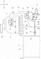
Fig. 1 is a left side view of the front of the body in the combine.
Fig. 2 is a perspective view showing the hydrostatic continuously variable transmission and the structure around the hydraulic oil tank.
Fig. 3 is a plan view showing the configuration of the hydrostatic continuously variable transmission and the periphery of the hydraulic oil tank.
Fig. 4 is a left side view showing the hydrostatic continuously variable transmission and the structure around the hydraulic oil tank.
Fig. 5 is a rear view showing the structure of the link mechanism.
Fig. 6 is a perspective view showing the structure of the cover.
Fig. 7 is a longitudinal sectional side view showing a mounting structure of the operating arm with respect to the trunnion.
Description of the reference numerals
1 combine harvester
2 cutting part
3 conveying part
4 threshing device
5 working oil tank
6 hydrostatic stepless speed change device
9 Motor
10-bar linkage mechanism
11 operating arm
12 output gear
13 sector gear
14 connecting rod
40 cover
52 first support
53 second support
63 trunnion
91 output shaft
Detailed Description
A mode for carrying out the present invention will be described based on the drawings. In the following description, the direction of arrow F shown in fig. 1, 3, 4, and 7 is referred to as "front", the direction of arrow B is referred to as "rear", the direction of arrow L shown in fig. 3 and 5 is referred to as "left", and the direction of arrow R is referred to as "right". The direction of arrow U shown in fig. 1, 4, 5, and 7 is referred to as "up", and the direction of arrow D is referred to as "down".
[ integral structure of combine harvester ]
As shown in fig. 1, a harvesting unit 2 and a conveying unit 3 are provided at the front of the body of a semi-feeding type combine 1. A threshing device 4 is provided behind the conveying unit 3.
The harvesting unit 2 harvests crops in a field. The conveying unit 3 conveys the crop harvested by the harvesting unit 2 to the threshing device 4.
Thus, the combine harvester 1 includes the harvesting unit 2 provided at the front of the machine body. The combine harvester 1 further includes a conveying unit 3 for conveying the crop harvested by the harvesting unit 2 to the threshing device 4.
Further, a hydraulic oil tank 5, a hydrostatic continuously variable transmission 6, and a pair of right and left crawler travel devices 7 are provided below the conveying unit 3. The working oil tank 5 is provided on the left side in the right-left direction of the body. The combine harvester 1 is also capable of self-traveling by the pair of left and right crawler traveling devices 7.
Thus, the combine harvester 1 includes the hydraulic oil tank 5, and the hydraulic oil tank 5 is provided at a left side portion in the left-right direction of the machine body below the conveying section 3.
The combine harvester 1 is provided with an engine (not shown). The pair of right and left crawler travel devices 7 are driven by power of the engine.
As shown in fig. 1, the harvesting section 2 includes a grain lifter 21, a cutter 22, a harvesting input housing 23, and a harvesting input shaft 24. The grain lifter 21 lifts up the grain stalks in the field. The grain stalks lifted by the grain lifter 21 are cut by the cutter 22. The straw cut by the cutter 22 is conveyed backward by the conveying unit 3.
The conveying unit 3 has a conveying chain 31. The conveyor chain 31 is located at the rear end of the conveying section 3. The grain and straw conveyed backward by the conveying section 3 is conveyed from the conveying chain 31 to the threshing device 4.
The cut-out input housing 23 is a cylindrical member provided in a state extending in the left-right direction of the machine body. A cutting input shaft 24 extending in the left-right direction of the machine body is disposed inside the cutting input housing 23.
As shown in fig. 1, the combine harvester 1 is provided with a harvesting portion rotating shaft 81. The cutting section rotating shaft 81 is provided in a state of extending downward from the left end portion of the cutting input housing 23.
As shown in fig. 1 and 2, a rotation shaft support portion 82 is fixed to the left side wall 51 of the hydraulic oil tank 5. The rotation shaft support portion 82 is a vertically long box-shaped member. An opening 82a is formed in the upper surface of the rotation shaft support portion 82. The lower portion of the cutting section rotating shaft 81 is inserted into the opening 82 a.
With this configuration, the cutting section rotation shaft 81 is supported by the rotation shaft support section 82. The cutting unit 2 is rotatable about the cutting unit rotation axis 81 with respect to the machine body.
[ Power Transmission route from Engine to harvesting Unit ]
As shown in fig. 2 and 3, the hydrostatic continuously variable transmission 6 includes an HST input pulley 61 and an HST output pulley 62. As shown in fig. 1 and 4, a cutting input pulley 83 is attached to the left end of the cutting input shaft 24.
As shown in fig. 4, the belt 84 is wound around the HST output pulley 62 and the cutting input pulley 83. In addition, the belt 84 is tensioned by a tensioning mechanism 85.
The power from the engine is transmitted to the HST input pulley 61 via an engine power transmission mechanism (not shown). The power transmitted to the HST input pulley 61 is shifted in the hydrostatic continuously variable transmission 6 and is output from the HST output pulley 62. The power output from the HST output pulley 62 is transmitted to the cutting input pulley 83 via a transmission belt 84.
The power transmitted to the harvesting input pulley 83 is transmitted to the harvesting input shaft 24. The power transmitted to the harvesting input shaft 24 is transmitted to the grain lifter 21, the cutter 22, and the conveying unit 3 in the harvesting unit 2 via a harvesting driving force transmission mechanism (not shown).
With this configuration, the power from the engine is shifted by the hydrostatic continuously variable transmission 6 and transmitted to the harvesting unit 2. That is, the hydrostatic continuously variable transmission 6 is configured to change the speed of the power transmitted to the cutting unit 2.
[ Structure of trunnion and Motor ]
As shown in fig. 3 to 5, the hydrostatic continuously variable transmission 6 has trunnions 63. The trunnion 63 protrudes toward the rear. If the trunnion 63 is operated, the angle of a swash plate (not shown) provided inside the hydrostatic continuously variable transmission 6 changes. Then, the change gear ratio in the hydrostatic continuously variable transmission 6 changes due to the change in the angle of the swash plate.
As shown in fig. 3 and 5, the combine harvester 1 includes a motor 9. The output shaft 91 of the motor 9 protrudes rearward. The trunnion 63 and the output shaft 91 are linked by the link mechanism 10.
Thus, the hydrostatic continuously variable transmission 6 and the motor 9 are arranged such that the trunnion 63 protrudes in the same direction as the output shaft 91 of the motor 9. The hydrostatic continuously variable transmission 6 and the motor 9 are disposed such that the trunnion 63 and the output shaft 91 of the motor 9 project rearward. The combine harvester 1 further includes a link mechanism 10 that links the trunnion 63 and the motor 9.
Further, with this structure, the motor 9 operates the trunnion 63 via the link mechanism 10.
[ hydrostatic stepless transmission and motor support Structure ]
As shown in fig. 2 and 5, a first bracket 52 is fixed to a left side wall 51 of the hydraulic oil tank 5. The hydrostatic continuously variable transmission 6 is supported by a left side wall 51 of the hydraulic oil tank 5 via a first bracket 52.
Thus, the combine harvester 1 includes the hydrostatic continuously variable transmission 6, and the hydrostatic continuously variable transmission 6 is supported by the left side wall 51 of the hydraulic oil tank 5 via the first bracket 52, and changes the speed of the power transmitted to the cutting unit 2.
Further, a second bracket 53 is fixed to a rear upper wall surface 54 in an outer peripheral portion of the hydraulic oil tank 5. The second bracket 53 has a first member 53a, a second member 53b, and a third member 53 c. The first member 53a, the second member 53b, and the third member 53c are plate-like members.
Thus, the second bracket 53 is supported by a portion of the outer peripheral portion of the hydraulic oil tank 5 that is different from the portion supporting the left side wall 51 of the first bracket 52. The second bracket 53 is supported by the rear upper portion of the hydraulic oil tank 5.
The first member 53a and the second member 53b are arranged in parallel with each other. The third member 53c is disposed perpendicular to the first member 53a and the second member 53 b.
The first member 53a is fixed to the rear upper wall surface 54 in a state of extending rearward from the rear upper wall surface 54. The second member 53b is disposed to extend upward. Further, a lower portion of the second member 53b overlaps with a rear end portion of the first member 53 a. Further, the rear end portion of the first member 53a and the lower side portion of the second member 53b are fastened by a bolt b 1.
The third member 53c is fixed to the second member 53b in a state of extending upward and leftward from the left side surface of the upper portion of the second member 53 b. The motor 9 is supported by the third member 53 c. That is, the motor 9 is supported by the second bracket 53.
Thus, the combine harvester 1 includes the motor 9, and the motor 9 is supported by the second bracket 53 different from the first bracket 52, and operates the trunnion 63 of the hydrostatic continuously variable transmission 6. The first bracket 52 and the second bracket 53 are supported by the working oil tank 5, respectively. The motor 9 is supported at the rear of the hydraulic oil tank 5 via a second bracket 53.
[ Structure of the cover ]
As shown in fig. 4 and 6, a cover 40 is provided above the hydraulic oil tank 5 and the hydrostatic continuously variable transmission 6. The cover 40 is positioned between the conveying unit 3 (see fig. 1) and the operating oil tank 5. In addition, as shown in fig. 4, the link mechanism 10 is located below the cover 40.
Thus, the cover 40 is provided between the conveying unit 3 and the operating oil tank 5. In addition, the link mechanism 10 is located below the cover 40.
As shown in fig. 4 and 6, the cover 40 includes a first cover 40a and a second cover 40 b. The first cover 40a is provided in a state of extending forward from the opening lower edge 4a of the threshing device 4. The opening lower edge portion 4a is an edge of the lower end portion of the opening that receives the harvested grain stalks in the threshing device 4.
As shown in fig. 2 to 4, a cover support bracket 55 is provided at an upper end portion of the operating oil tank 5. As shown in fig. 4 and 6, the second cover 40b is disposed so as to straddle the front end of the first cover 40a and the cover support bracket 55.
The cover 40 can prevent stalk chips and the like from accumulating on the link mechanism 10.
[ Structure of Link mechanism ]
As shown in fig. 5, the link mechanism 10 includes an operation arm 11, an output gear 12, a sector gear 13, and a connecting rod 14.
The lower portion of the operating arm 11 is mounted to the trunnion 63. Further, the output gear 12 is attached to an output shaft 91 of the motor 9.
The sector gear 13 is supported by the third member 53c of the second bracket 53 so as to be rotatable about an axial center P1 along the front-rear direction of the machine body. The sector gear 13 engages with the output gear 12. That is, the sector gear 13 is rotated by the rotation of the output gear 12.
Thus, the link mechanism 10 includes: an output gear 12 attached to the output shaft 91; and a sector gear 13 engaged with the output gear 12 and rotated by rotation of the output gear 12. The sector gear 13 is supported by the second bracket 53.
The connecting rod 14 is provided in a state where the sector gear 13 is coupled to the upper end portion of the operating arm 11. In addition, the connecting rod 14 is disposed in a horizontal posture.
Thus, the link mechanism 10 has the link lever 14 in the horizontal posture for coupling the operation arm 11 and the sector gear 13.
The connecting rod 14 and the sector gear 13 are coupled to each other so as to be relatively rotatable about an axial center P2 along the front-rear direction of the machine body. The link lever 14 and the operation arm 11 are coupled to each other so as to be rotatable relative to each other about an axis P3 extending in the front-rear direction of the machine body.
[ action of the link mechanism ]
When the output shaft 91 of the motor 9 rotates clockwise in fig. 5, the output gear 12 also rotates in the same direction. At this time, the sector gear 13 rotates counterclockwise in fig. 5 about the shaft core P1. Thereby, the upper end portion of the operation arm 11 is pressed toward the left side via the connection rod 14.
By pressing the upper end portion of the operating arm 11 toward the left side, the operating arm 11 rotates about the trunnion 63 in the counterclockwise direction in fig. 5. Accompanying this, the trunnion 63 rotates counterclockwise in fig. 5.
That is, the trunnion 63 rotates counterclockwise in fig. 5 by the above-described series of operations of the link mechanism 10.
When the output shaft 91 of the motor 9 rotates counterclockwise in fig. 5, the output gear 12 also rotates in the same direction. At this time, the sector gear 13 rotates clockwise in fig. 5 about the shaft core P1. Thereby, the upper end portion of the operation arm 11 is pulled toward the right side via the link 14.
By pulling the upper end portion of the operating arm 11 toward the right side, the operating arm 11 rotates clockwise in fig. 5 about the trunnion 63. Accompanying this, the trunnion 63 rotates clockwise in fig. 5.
That is, the trunnion 63 rotates clockwise in fig. 5 by the above-described series of operations of the link mechanism 10.
As described above, the trunnion 63 is operated by the rotation of the operating arm 11 in accordance with the series of operations of the link mechanism 10. In addition, according to the configuration of the link mechanism 10 described above, the operating arm 11, the sector gear 13, and the connecting rod 14 move along a plane perpendicular to the trunnion 63 and the output shaft 91.
Thus, the link mechanism 10 has the operating arm 11 attached to the trunnion 63 and operating the trunnion 63. The link mechanism 10 is configured to operate along a plane perpendicular to the trunnion 63 and the output shaft 91.
[ Structure relating to vibration-proof rubber ]
As shown in fig. 7, the shaft holding member 15 is fixed to the trunnion 63. The shaft holding member 15 and the trunnion 63 are fastened together by a bolt b2 in a relatively non-rotatable state.
The shaft holding member 15 holds two vibration-proof rubbers 16. The vibration-proof rubber 16 is formed in a cylindrical shape and is arranged to extend in the front-rear direction of the machine body. Also, the two vibration-proof rubbers 16 are arranged such that the trunnion 63 is located between the two vibration-proof rubbers 16.
A boss member 17 is inserted into each of the two vibration-proof rubbers 16. The operation arm 11 is fastened to the two boss members 17 by bolts b 3.
With this structure, the operation arm 11 is attached to the trunnion 63 via the vibration-proof rubber 16. Thereby, the vibration of the hydrostatic continuously variable transmission 6 is reduced by the vibration-proof rubber 16. Therefore, the vibration of the hydrostatic continuously variable transmission 6 is hardly transmitted to the link mechanism 10 and the motor 9.
According to the configuration described above, the hydrostatic continuously variable transmission 6 is supported by the hydraulic oil tank 5 via the first bracket 52. The motor 9 is supported by the hydraulic oil tank 5 via a second bracket 53. Therefore, the first bracket 52, the hydraulic oil tank 5, and the second bracket 53 are mounted between the hydrostatic continuously variable transmission 6 and the motor 9. That is, the vibration of the hydrostatic continuously variable transmission 6 is transmitted to the first carrier 52, the hydraulic oil tank 5, the second carrier 53, and the motor 9 in this order.
Thus, the vibration of the hydrostatic continuously variable transmission 6 is reduced by being transmitted to the first bracket 52, the hydraulic oil tank 5, and the second bracket 53 before being transmitted to the motor 9. Therefore, according to the present invention, the vibration of the hydrostatic continuously variable transmission 6 is hardly transmitted to the motor 9.
Further, according to the present invention, the motor 9 can be disposed in a state of being far from the trunnion 63, as compared with a configuration directly related to the trunnion 63 and the motor 9.
Therefore, a working space is easily secured around the trunnion 63. This improves the maintainability of the trunnion 63.
[ other embodiments ]
(1) The hydraulic oil tank 5 may be provided on the right side of the machine body, the first bracket 52 may be fixed to the right side wall of the hydraulic oil tank 5, and the hydrostatic continuously variable transmission 6 may be supported on the right side wall of the hydraulic oil tank 5 via the first bracket 52.
(2) Instead of the pair of right and left crawler travel devices 7, a pair of right and left wheel travel devices may be provided. In addition, the running gear may be a semi-crawler type.
(3) The cutting unit 2 may be provided in a state of being unable to rotate with respect to the machine body.
(4) The cover 40 may not be provided.
(5) The sector gear 13 may be supported by a support member provided separately from the second bracket 53.
(6) The link mechanism 10 is not limited to the configuration of the above embodiment as long as it links the trunnion 63 with the motor 9. For example, the link mechanism 10 may be constituted only by a plurality of gears that link the trunnion 63 with the motor 9.
(7) The trunnion 63 and the output shaft 91 of the motor 9 may protrude toward different directions from each other. For example, the trunnion 63 may protrude rearward, and the output shaft 91 may protrude forward. The trunnion 63 may protrude leftward, and the output shaft 91 may protrude rightward.
(8) Both the first bracket 52 and the second bracket 53 may be fixed to the left side wall 51 of the operating oil tank 5.
Industrial applicability of the invention
The invention is not only applied to the semi-feeding type combine harvester, but also applied to the full-feeding type combine harvester.
Claims (9)
1. A combine harvester is characterized by comprising:
a cutting part arranged at the front part of the machine body;
a conveying section for conveying the crop harvested by the harvesting section to a threshing device;
a working oil tank provided at one side of the machine body below the conveying part in the left-right direction;
a hydrostatic continuously variable transmission supported by the one side wall of the hydraulic oil tank via a first bracket, and configured to change a speed of power transmitted to the cutting unit;
a motor supported by a second bracket different from the first bracket and operating a trunnion of the hydrostatic continuously variable transmission;
the first bracket and the second bracket are respectively supported on the working oil tank,
the link mechanism is provided for linking the trunnion and the motor.
2. A combine harvester according to claim 1,
the hydrostatic continuously variable transmission and the motor are arranged such that the trunnion and the output shaft of the motor protrude in the same direction,
the link mechanism is configured to operate along a plane perpendicular to the trunnion and the output shaft.
3. A combine harvester according to claim 2,
the link mechanism has:
an operating arm that is mounted to the trunnion and operates the trunnion;
an output gear attached to the output shaft;
a sector gear engaged with the output gear and rotated by rotation of the output gear;
and a link lever that is in a horizontal posture and connects the operation arm and the sector gear.
4. A combine harvester according to claim 3,
the sector gear is supported by the second bracket.
5. A combine harvester according to any one of the claims 1-4,
the second bracket is supported by a portion of the outer peripheral portion of the operating oil tank that is different from a side wall that supports the first bracket.
6. A combine harvester according to claim 5,
the motor is supported at the rear of the operating oil tank via the second bracket,
the hydrostatic continuously variable transmission and the motor are arranged such that the trunnion and the output shaft of the motor protrude rearward.
7. A combine harvester according to claim 5,
the second bracket is supported at the rear upper portion of the operating oil tank.
8. A combine harvester according to claim 6,
the second bracket is supported at the rear upper portion of the operating oil tank.
9. A combine harvester according to any one of the claims 1-4,
a cover is provided between the conveying part and the operating oil tank,
the linkage mechanism is located below the cover.
Applications Claiming Priority (2)
| Application Number | Priority Date | Filing Date | Title |
|---|---|---|---|
| JP2016-247052 | 2016-12-20 | ||
| JP2016247052A JP6618458B2 (en) | 2016-12-20 | 2016-12-20 | Combine |
Publications (2)
| Publication Number | Publication Date |
|---|---|
| CN108200802A CN108200802A (en) | 2018-06-26 |
| CN108200802B true CN108200802B (en) | 2022-04-26 |
Family
ID=62605790
Family Applications (1)
| Application Number | Title | Priority Date | Filing Date |
|---|---|---|---|
| CN201711372212.2A Expired - Fee Related CN108200802B (en) | 2016-12-20 | 2017-12-19 | Combine harvester |
Country Status (3)
| Country | Link |
|---|---|
| JP (1) | JP6618458B2 (en) |
| KR (1) | KR102470910B1 (en) |
| CN (1) | CN108200802B (en) |
Families Citing this family (1)
| Publication number | Priority date | Publication date | Assignee | Title |
|---|---|---|---|---|
| JP2023108645A (en) * | 2022-01-26 | 2023-08-07 | フジイコーポレーション株式会社 | lawn mower |
Citations (5)
| Publication number | Priority date | Publication date | Assignee | Title |
|---|---|---|---|---|
| US6250414B1 (en) * | 1997-09-18 | 2001-06-26 | Kubota Corporation | Working vehicle |
| US20030216216A1 (en) * | 2002-04-18 | 2003-11-20 | Nsk Ltd. | Apparatus and method for controlling transmission ratio of toroidal-type continuously variable transmission unit for continuously variable transmission apparatus |
| CN202587856U (en) * | 2011-10-27 | 2012-12-12 | 井关农机株式会社 | Combine harvester |
| CN103858587A (en) * | 2012-12-11 | 2014-06-18 | 株式会社久保田 | combine harvester |
| CN105309110A (en) * | 2014-05-29 | 2016-02-10 | 井关农机株式会社 | Combine harvester |
Family Cites Families (8)
| Publication number | Priority date | Publication date | Assignee | Title |
|---|---|---|---|---|
| US6390227B1 (en) * | 1995-03-30 | 2002-05-21 | Kanzaki Kokyukoki Mfg. Co., Ltd. | Axle driving unit for a lawn tractor |
| JPH1054461A (en) * | 1996-08-09 | 1998-02-24 | Kubota Corp | Continuously variable transmission for work equipment |
| JP4626740B2 (en) * | 2003-11-27 | 2011-02-09 | 井関農機株式会社 | Working machine |
| JP4667133B2 (en) * | 2005-06-20 | 2011-04-06 | 三菱農機株式会社 | Sector gear rotation angle detection device |
| JP2008162435A (en) * | 2006-12-28 | 2008-07-17 | Mitsubishi Agricult Mach Co Ltd | Hydraulic-driven type working vehicle |
| JP5408444B2 (en) * | 2010-03-12 | 2014-02-05 | 井関農機株式会社 | Combine |
| US8622871B2 (en) * | 2010-12-20 | 2014-01-07 | Caterpillar Inc. | Control arrangement and method of controlling a transmission in a machine |
| JP5916593B2 (en) * | 2012-12-11 | 2016-05-11 | 株式会社クボタ | Combine |
-
2016
- 2016-12-20 JP JP2016247052A patent/JP6618458B2/en active Active
-
2017
- 2017-12-13 KR KR1020170171064A patent/KR102470910B1/en active Active
- 2017-12-19 CN CN201711372212.2A patent/CN108200802B/en not_active Expired - Fee Related
Patent Citations (5)
| Publication number | Priority date | Publication date | Assignee | Title |
|---|---|---|---|---|
| US6250414B1 (en) * | 1997-09-18 | 2001-06-26 | Kubota Corporation | Working vehicle |
| US20030216216A1 (en) * | 2002-04-18 | 2003-11-20 | Nsk Ltd. | Apparatus and method for controlling transmission ratio of toroidal-type continuously variable transmission unit for continuously variable transmission apparatus |
| CN202587856U (en) * | 2011-10-27 | 2012-12-12 | 井关农机株式会社 | Combine harvester |
| CN103858587A (en) * | 2012-12-11 | 2014-06-18 | 株式会社久保田 | combine harvester |
| CN105309110A (en) * | 2014-05-29 | 2016-02-10 | 井关农机株式会社 | Combine harvester |
Also Published As
| Publication number | Publication date |
|---|---|
| KR102470910B1 (en) | 2022-11-28 |
| JP2018099075A (en) | 2018-06-28 |
| CN108200802A (en) | 2018-06-26 |
| KR20180071954A (en) | 2018-06-28 |
| JP6618458B2 (en) | 2019-12-11 |
Similar Documents
| Publication | Publication Date | Title |
|---|---|---|
| JP2014113111A (en) | Combine harvester | |
| CN205284216U (en) | Harvester | |
| CN108200802B (en) | Combine harvester | |
| CN103858587A (en) | combine harvester | |
| JP4288145B2 (en) | Combine gearing | |
| JP4860341B2 (en) | Work vehicle | |
| JP6333127B2 (en) | Combine | |
| JP4241723B2 (en) | Combine harvester drive structure | |
| JP6095544B2 (en) | Combine | |
| JP6524946B2 (en) | Combine | |
| CN108496532B (en) | Harvester | |
| CN103875354A (en) | Reaping Apparatus Of A Combine-harvester | |
| CN114642117B (en) | Combine harvester | |
| JP2003102238A (en) | Combine | |
| JP7274968B2 (en) | combine | |
| JP5532452B2 (en) | Combine | |
| JP4818841B2 (en) | Combine | |
| JP4816235B2 (en) | Combine | |
| JP6289315B2 (en) | Combine | |
| JP4720461B2 (en) | Combine | |
| JP3831516B2 (en) | Combine | |
| WO2020085419A1 (en) | Harvester and work vehicle | |
| JP3831520B2 (en) | Combine | |
| JP2021042830A (en) | Work vehicle | |
| JP2007300894A5 (en) |
Legal Events
| Date | Code | Title | Description |
|---|---|---|---|
| PB01 | Publication | ||
| PB01 | Publication | ||
| SE01 | Entry into force of request for substantive examination | ||
| SE01 | Entry into force of request for substantive examination | ||
| GR01 | Patent grant | ||
| GR01 | Patent grant | ||
| CF01 | Termination of patent right due to non-payment of annual fee | ||
| CF01 | Termination of patent right due to non-payment of annual fee |
Granted publication date: 20220426 |