CN108201746B - A multifunctional air pollution control system - Google Patents
A multifunctional air pollution control system Download PDFInfo
- Publication number
- CN108201746B CN108201746B CN201810071398.6A CN201810071398A CN108201746B CN 108201746 B CN108201746 B CN 108201746B CN 201810071398 A CN201810071398 A CN 201810071398A CN 108201746 B CN108201746 B CN 108201746B
- Authority
- CN
- China
- Prior art keywords
- welded
- gas
- control system
- air
- pulley
- Prior art date
- Legal status (The legal status is an assumption and is not a legal conclusion. Google has not performed a legal analysis and makes no representation as to the accuracy of the status listed.)
- Active
Links
Images


Classifications
-
- B—PERFORMING OPERATIONS; TRANSPORTING
- B01—PHYSICAL OR CHEMICAL PROCESSES OR APPARATUS IN GENERAL
- B01D—SEPARATION
- B01D46/00—Filters or filtering processes specially modified for separating dispersed particles from gases or vapours
- B01D46/10—Particle separators, e.g. dust precipitators, using filter plates, sheets or pads having plane surfaces
-
- A—HUMAN NECESSITIES
- A61—MEDICAL OR VETERINARY SCIENCE; HYGIENE
- A61L—METHODS OR APPARATUS FOR STERILISING MATERIALS OR OBJECTS IN GENERAL; DISINFECTION, STERILISATION OR DEODORISATION OF AIR; CHEMICAL ASPECTS OF BANDAGES, DRESSINGS, ABSORBENT PADS OR SURGICAL ARTICLES; MATERIALS FOR BANDAGES, DRESSINGS, ABSORBENT PADS OR SURGICAL ARTICLES
- A61L9/00—Disinfection, sterilisation or deodorisation of air
- A61L9/16—Disinfection, sterilisation or deodorisation of air using physical phenomena
- A61L9/18—Radiation
- A61L9/20—Ultraviolet radiation
-
- B—PERFORMING OPERATIONS; TRANSPORTING
- B01—PHYSICAL OR CHEMICAL PROCESSES OR APPARATUS IN GENERAL
- B01D—SEPARATION
- B01D53/00—Separation of gases or vapours; Recovering vapours of volatile solvents from gases; Chemical or biological purification of waste gases, e.g. engine exhaust gases, smoke, fumes, flue gases, aerosols
- B01D53/02—Separation of gases or vapours; Recovering vapours of volatile solvents from gases; Chemical or biological purification of waste gases, e.g. engine exhaust gases, smoke, fumes, flue gases, aerosols by adsorption, e.g. preparative gas chromatography
- B01D53/04—Separation of gases or vapours; Recovering vapours of volatile solvents from gases; Chemical or biological purification of waste gases, e.g. engine exhaust gases, smoke, fumes, flue gases, aerosols by adsorption, e.g. preparative gas chromatography with stationary adsorbents
-
- B—PERFORMING OPERATIONS; TRANSPORTING
- B01—PHYSICAL OR CHEMICAL PROCESSES OR APPARATUS IN GENERAL
- B01D—SEPARATION
- B01D2221/00—Applications of separation devices
- B01D2221/08—Mobile separation devices
-
- B—PERFORMING OPERATIONS; TRANSPORTING
- B01—PHYSICAL OR CHEMICAL PROCESSES OR APPARATUS IN GENERAL
- B01D—SEPARATION
- B01D2253/00—Adsorbents used in seperation treatment of gases and vapours
- B01D2253/10—Inorganic adsorbents
- B01D2253/102—Carbon
Landscapes
- Chemical & Material Sciences (AREA)
- Chemical Kinetics & Catalysis (AREA)
- Health & Medical Sciences (AREA)
- Epidemiology (AREA)
- Life Sciences & Earth Sciences (AREA)
- Animal Behavior & Ethology (AREA)
- General Health & Medical Sciences (AREA)
- Public Health (AREA)
- Veterinary Medicine (AREA)
- Engineering & Computer Science (AREA)
- Analytical Chemistry (AREA)
- General Chemical & Material Sciences (AREA)
- Oil, Petroleum & Natural Gas (AREA)
- Filtering Of Dispersed Particles In Gases (AREA)
- Apparatus For Disinfection Or Sterilisation (AREA)
Abstract
本发明提供一种多功能的大气污染防治系统,包括储药箱,进药头,出气管,第一风机,加热管,气体过滤箱结构,漂浮气体收集管结构,大气监测板结构,防护罩结构,移动板结构和控制器,所述的进药头和出气管分别焊接在储药箱的左上部和右上部;所述的第一风机法兰连接在出气管的上端;所述的加热管安装在储药箱内部的下方。本发明的有益效果为:通过气体过滤箱结构的设置,有利于在完成收集气体后,可以方便的过滤收集来的有害气体,同时也增加了该大气污染治理系统的治理效果,通过漂浮气体收集管结构的设置,有利于方便的使连接软管停留在半空中,同时也方便的收集半空中的有害气体。
The invention provides a multifunctional air pollution prevention and control system, which includes a medicine storage box, a medicine inlet head, an air outlet pipe, a first fan, a heating pipe, a gas filter box structure, a floating gas collection pipe structure, an air monitoring plate structure, and a protective cover. structure, moving plate structure and controller, the medicine inlet head and the air outlet pipe are welded on the upper left and right upper parts of the medicine storage box respectively; the first fan flange is connected to the upper end of the air outlet pipe; the heating The tube is installed under the interior of the medicine storage tank. The beneficial effects of the present invention are: through the arrangement of the gas filter box structure, the collected harmful gas can be conveniently filtered after the gas is collected, and at the same time, the control effect of the air pollution control system is also increased. The arrangement of the pipe structure is conducive to conveniently keeping the connecting hose in the mid-air, and at the same time, it is also convenient to collect the harmful gas in the mid-air.
Description
技术领域technical field
本发明属于大气污染防治装置技术领域,尤其涉及一种多功能的大气污染防治系统。The invention belongs to the technical field of air pollution prevention and control devices, and in particular relates to a multifunctional air pollution prevention and control system.
背景技术Background technique
大气净化装置可以对被污染的大气进行除杂,净化等的处理工作,防止污染太过严重,使大气层无法修复,加快全球气候变暖的速度,因此通过大气污染治理的方法来进行治理,现有技术为中国专利公开号为CN201710862749.0的一种大气污染净化装置所采用的技术方案是:包括净化罐、喷淋仓、过滤仓、过滤装置、喷淋装置、维修门、法兰、进气口、出气口、进水口、铰链、手槽、支脚,所述净化罐左侧通过法兰设有进气口,所述净化罐右侧通过法兰设有出气口,所述进气口、出气口以及净化罐处于同一条中心线上,所述净化罐中间分别设有喷淋仓和过滤仓,所述净化罐通过过滤仓设有过滤装置,所述过滤装置由初步过滤网、活性炭过滤网、聚丙烯过滤网组成。The air purification device can remove impurities and purify the polluted atmosphere, prevent the pollution from being too serious, make the atmosphere irreparable, and accelerate the speed of global warming. The technical solution adopted by the prior art is an air pollution purification device with a Chinese patent publication number of CN201710862749.0: including a purification tank, a spray chamber, a filter chamber, a filter device, a spray device, a maintenance door, a flange, an inlet Air port, air outlet, water inlet, hinge, hand groove, support feet, the left side of the purification tank is provided with an air inlet through the flange, the right side of the purification tank is provided with an air outlet through the flange, the air inlet , the air outlet and the purification tank are on the same center line, the middle of the purification tank is provided with a spray chamber and a filter chamber, the purification tank is provided with a filter device through the filter chamber, and the filter device is composed of a preliminary filter screen, activated carbon It is composed of filter screen and polypropylene filter screen.
但是,现有的大气污染防治系统还存在着不方便过滤并消毒有害的气体、不方便检测半空中不同位置的质量、不方便移动该系统和不方便对工作人员进行防护的问题。However, the existing air pollution prevention and control system still has the problems of inconvenient to filter and sterilize harmful gases, inconvenient to detect the quality of different positions in midair, inconvenient to move the system and inconvenient to protect the staff.
因此,发明一种多功能的大气污染防治系统显得非常必要。Therefore, it is very necessary to invent a multifunctional air pollution control system.
发明内容SUMMARY OF THE INVENTION
为了解决上述技术问题,本发明提供一种多功能的大气污染防治系统,以解决现有的大气污染防治系统不方便过滤并消毒有害的气体、不方便检测半空中不同位置的质量、不方便移动该系统和不方便对工作人员进行防护的问题。一种多功能的大气污染防治系统,包括储药箱,进药头,出气管,第一风机,加热管,气体过滤箱结构,漂浮气体收集管结构,大气监测板结构,防护罩结构,移动板结构和控制器,所述的进药头和出气管分别焊接在储药箱的左上部和右上部;所述的第一风机法兰连接在出气管的上端;所述的加热管安装在储药箱内部的下方;所述的气体过滤箱结构上端与储药箱焊接,下端与移动板结构焊接;所述的漂浮气体收集管结构分别与储药箱的左端和气体过滤箱结构的左上部焊接;所述的大气监测板结构焊接在移动板结构的右上部;所述的防护罩结构焊接在移动板结构的右端;所述的控制器螺栓安装在气体过滤箱结构的右上部;所述的气体过滤箱结构包括吸气箱,插接孔,竖立条,第二风机,吸气头,插接架,第一过滤网,拿放手柄,连通头,消毒壳,出气头,固定板和消毒灯,所述的吸气箱左右两端分别焊接有吸气头和消毒壳;所述的竖立条焊接在吸气箱内壁的中左侧,并在正表面上螺栓安装有第二风机;所述的第一过滤网和拿放手柄分别安装在插接架的内壁和上端;所述的连通头焊接在消毒壳的左下部,并镶嵌在吸气箱的右下部;所述的出气头焊接在消毒壳的右上部;所述的固定板焊接在消毒壳内壁上方的左侧,并在左表面上安装有消毒灯。In order to solve the above technical problems, the present invention provides a multifunctional air pollution prevention and control system to solve the problem that the existing air pollution prevention and control system is inconvenient to filter and sterilize harmful gases, inconvenient to detect the quality of different positions in midair, and inconvenient to move The system and the inconvenience of protecting the staff. A multifunctional air pollution prevention and control system, including a medicine storage box, a medicine inlet head, an air outlet pipe, a first fan, a heating pipe, a gas filter box structure, a floating gas collection pipe structure, an atmospheric monitoring board structure, a protective cover structure, a mobile Plate structure and controller, the medicine inlet and the gas outlet pipe are respectively welded on the upper left and right upper parts of the medicine storage box; the first fan flange is connected to the upper end of the gas outlet pipe; the heating pipe is installed on the Below the inside of the medicine storage box; the upper end of the gas filter box structure is welded with the medicine storage box, and the lower end is welded with the moving plate structure; the floating gas collecting pipe structure is respectively connected with the left end of the medicine storage box and the upper left of the gas filter box structure the upper right part of the structure of the air monitoring board is welded; the structure of the protective cover is welded to the right end of the structure of the movable board; the bolt of the controller is installed on the upper right part of the structure of the gas filter box; The structure of the gas filter box includes a suction box, a plug hole, a vertical bar, a second fan, a suction head, a plug frame, a first filter screen, a handle for handling, a communication head, a sterilization shell, an air outlet, and a fixing plate. and disinfection lamp, the left and right ends of the suction box are respectively welded with a suction head and a disinfection shell; the vertical strip is welded on the middle left side of the inner wall of the suction box, and a second fan is bolted on the front surface. The described first filter screen and the handle for taking and placing are respectively installed on the inner wall and the upper end of the plug-in frame; the described communication head is welded on the lower left part of the sterilization shell and is embedded in the lower right part of the suction box; the described air outlet The head is welded on the upper right part of the sterilization shell; the fixing plate is welded on the left side above the inner wall of the sterilization shell, and a sterilization lamp is installed on the left surface.
优选的,所述的漂浮气体收集管结构包括竖板,插接轴承,旋转杆,旋转手柄,第三风机,连接软管,吸风头,连接绳和第一氢气球,所述的插接轴承镶嵌在竖板内壁的上方,并在内部插接有旋转杆;所述的旋转手柄焊接在旋转杆的左端;所述的连接软管上端与吸风头胶接,下端缠绕在旋转杆的外壁上,并与第三风机连接;所述的连接绳一端与连接软管连接,另一端与第一氢气球连接。Preferably, the floating gas collection tube structure includes a vertical plate, a plug bearing, a rotating rod, a rotating handle, a third fan, a connecting hose, a suction head, a connecting rope and a first hydrogen balloon, and the plug bearing The upper end of the connecting hose is glued with the suction head, and the lower end is wrapped around the outer wall of the rotating rod. , and is connected with the third fan; one end of the connecting rope is connected with the connecting hose, and the other end is connected with the first hydrogen balloon.
优选的,所述的大气监测板结构包括滑轮杆,下滑轮,升降绳,上滑轮,固定绳,第二氢气球,连接盘和传感器,所述的下滑轮轴接在滑轮杆的上端;所述的升降绳套接在下滑轮和上滑轮之间;所述的固定绳一端与上滑轮连接,另一端与第二氢气球连接;所述的连接盘焊接在升降绳的左端,并在左表面上安装有传感器。Preferably, the air monitoring board structure includes a pulley rod, a lower pulley, a lifting rope, an upper pulley, a fixed rope, a second hydrogen balloon, a connecting plate and a sensor, and the lower pulley shaft is connected to the upper end of the pulley rod; the The lifting rope is sleeved between the lower pulley and the upper pulley; one end of the fixed rope is connected with the upper pulley, and the other end is connected with the second hydrogen balloon; the connecting plate is welded on the left end of the lifting rope, and is on the left surface A sensor is installed.
优选的,所述的防护罩结构包括第一固定架,第二固定架,防护布,过滤管,第二过滤网和辅助轮,所述的第二固定架分别焊接在第一固定架的左右两端;所述的过滤管镶嵌在防护布正表面的右上部,并在内部镶嵌有第二过滤网;所述的辅助轮分别螺栓安装在第一固定架右下部的前后两侧。Preferably, the protective cover structure includes a first fixing frame, a second fixing frame, a protective cloth, a filter tube, a second filter screen and an auxiliary wheel, and the second fixing frame is welded to the left and right of the first fixing frame respectively. two ends; the filter tube is inlaid on the upper right part of the front surface of the protective cloth, and a second filter screen is inlaid inside; the auxiliary wheels are respectively bolted on the front and rear sides of the lower right part of the first fixing frame.
优选的,所述的移动板结构包括底板,移动轮,安装螺栓,推手和推杆,所述的移动轮分别通过安装螺栓安装在底板下表面的左右两侧;所述的推手一端与底板焊接,另一端与推杆焊接。Preferably, the moving plate structure includes a bottom plate, a moving wheel, mounting bolts, a push handle and a push rod, and the moving wheel is respectively installed on the left and right sides of the lower surface of the bottom plate through mounting bolts; one end of the push handle is welded to the bottom plate , and the other end is welded with the push rod.
优选的,所述的控制器包括PLC,显示器,控制按键和安装块,所述的显示器和控制按键分别电性连接在PLC的右表面;所述的安装块分别焊接在PLC前后两部的下侧。Preferably, the controller includes a PLC, a display, a control button and an installation block, the display and the control button are respectively electrically connected to the right surface of the PLC; the installation block is welded to the lower part of the front and rear parts of the PLC, respectively. side.
优选的,所述的插接架具体采用回形不锈钢架,所述的插接架穿过插接孔并插接在吸气箱内部的右侧;所述的插接架内部的第一过滤网设置有两个,所述的第一过滤网分别采用活性炭滤网和HEPA滤网。Preferably, the plug-in frame is a stainless steel frame with a circular shape, and the plug-in frame passes through the plug-in hole and is plugged into the right side inside the suction box; the first filter inside the plug-in frame There are two screens, and the first filter screen adopts activated carbon filter screen and HEPA filter screen respectively.
优选的,所述的消毒灯具体紫外线灯,所述的消毒灯固定在固定板的左表面,并与连通头正对设置。Preferably, the disinfection lamp is specifically an ultraviolet lamp, and the disinfection lamp is fixed on the left surface of the fixing plate and is arranged opposite to the communication head.
优选的,所述的第一氢气球设置有两个,所述的第一氢气球分别通过连接绳与连接软管连接,所述的第一氢气球下端与吸风头上端之间的间距为五厘米至七厘米。Preferably, there are two first hydrogen balloons, the first hydrogen balloons are respectively connected with connecting hoses through connecting ropes, and the distance between the lower end of the first hydrogen balloon and the upper end of the suction head is five centimeters to seven centimeters.
优选的,所述的旋转杆插接在竖板内壁上方的插接轴承内,所述的旋转杆外壁的右侧缠绕有连接软管,所述的连接软管下端的第三风机与气体过滤箱结构连接。Preferably, the rotating rod is inserted into the plug bearing above the inner wall of the vertical plate, the right side of the outer wall of the rotating rod is wound with a connecting hose, and the third fan at the lower end of the connecting hose is connected to the gas filter Box structure connection.
优选的,所述的上滑轮通过固定绳上的第二氢气球处在半空中,所述的上滑轮通过升降绳限制住高度,所述的连接盘与升降绳胶接。Preferably, the upper pulley is in midair by the second hydrogen balloon on the fixed rope, the height of the upper pulley is limited by the lifting rope, and the connecting plate is glued to the lifting rope.
优选的,所述的连接盘左表面上开设有多个螺纹孔,所述的连接盘上的螺纹孔从上到下依次小一毫米至三毫米,所述的连接盘左表面上安装有传感器,所述的传感器设置有多个,所述的传感器分别采用大气环境传感器或者其它的传感器。Preferably, a plurality of threaded holes are opened on the left surface of the connecting plate, the threaded holes on the connecting plate are one millimeter to three millimeters smaller from top to bottom, and a sensor is installed on the left surface of the connecting plate , there are a plurality of the sensors, and the sensors respectively adopt atmospheric environment sensors or other sensors.
优选的,所述的第一固定架和第二固定架的内壁上分别胶接有防护布,所述的防护布具体采用PVC透明塑料布,所述的第二固定架右表面的内壁上的防护布上缝接有拉链。Preferably, protective cloths are glued on the inner walls of the first fixing frame and the second fixing frame respectively, and the protective cloth is specifically made of PVC transparent plastic cloth, and the inner wall on the right surface of the second fixing frame is A zipper is sewn on the protective cloth.
优选的,所述的过滤管内部的第二过滤网具体采用活性炭过滤网,所述的过滤管分别与防护布内侧和外界连通。Preferably, the second filter screen inside the filter tube is specifically an activated carbon filter screen, and the filter tube is respectively communicated with the inside of the protective cloth and the outside.
优选的,所述的底板下表面的移动轮具体采用带有刹车片的万向轮。Preferably, the moving wheel on the lower surface of the bottom plate is a universal wheel with brake pads.
优选的,所述的推手上部向右倾斜,所述的推手上端的推杆外壁上设置有一字防滑纹。Preferably, the upper part of the push handle is inclined to the right, and an anti-skid pattern is provided on the outer wall of the push rod at the upper end of the push handle.
优选的,所述的PLC分别与气体过滤箱结构、漂浮气体收集管结构和大气监测板结构电性连接。Preferably, the PLC is electrically connected to the structure of the gas filter box, the structure of the floating gas collection pipe and the structure of the atmospheric monitoring board, respectively.
优选的,所述的PLC具体采用型号为三菱FX2N-48的PLC。Preferably, the PLC specifically adopts a PLC with a model of Mitsubishi FX2N-48.
与现有技术相比,本发明的有益效果为:Compared with the prior art, the beneficial effects of the present invention are:
1.本发明中,所述的插接架具体采用回形不锈钢架,所述的插接架穿过插接孔并插接在吸气箱内部的右侧;所述的插接架内部的第一过滤网设置有两个,所述的第一过滤网分别采用活性炭滤网和HEPA滤网,有利于在完成收集气体后,可以方便的过滤收集来的有害气体,同时也增加了该大气污染治理系统的治理效果。1. In the present invention, the said plug-in rack specifically adopts a return-shaped stainless steel frame, and the said plug-in rack passes through the plug-in hole and is plugged on the right side inside the suction box; There are two first filter screens. The first filter screen adopts activated carbon filter screen and HEPA filter screen respectively, which is beneficial to filter the collected harmful gas after the gas is collected, and also increases the atmospheric pressure. The effect of pollution control system.
2.本发明中,所述的消毒灯具体紫外线灯,所述的消毒灯固定在固定板的左表面,并与连通头正对设置,有利于在完成过滤气体后,可以方便的对气体进行消毒,同时也增加了该气体过滤箱结构进化的效果。2. In the present invention, the disinfection lamp is specifically an ultraviolet lamp, and the disinfection lamp is fixed on the left surface of the fixed plate, and is set directly opposite to the communication head, which is beneficial to the completion of filtering the gas, and the gas can be easily cleaned. Disinfection also increases the effect of structural evolution of the gas filter box.
3.本发明中,所述的第一氢气球设置有两个,所述的第一氢气球分别通过连接绳与连接软管连接,所述的第一氢气球下端与吸风头上端之间的间距为五厘米至七厘米,有利于方便的使连接软管停留在半空中,同时也方便的收集半空中的有害气体。3. In the present invention, two of the first hydrogen balloons are provided, the first hydrogen balloons are respectively connected with the connecting hose through the connecting rope, and the space between the lower end of the first hydrogen balloon and the upper end of the suction head is The spacing is five to seven centimeters, which is convenient for keeping the connecting hose in mid-air, and at the same time, it is convenient to collect harmful gas in mid-air.
4.本发明中,所述的旋转杆插接在竖板内壁上方的插接轴承内,所述的旋转杆外壁的右侧缠绕有连接软管,所述的连接软管下端的第三风机与气体过滤箱结构连接,有利于方便的收纳该漂浮气体收集管结构,同时在收集气体后,可以方便的进行进化消毒的工作。4. In the present invention, the rotating rod is inserted into the plug bearing above the inner wall of the vertical plate, the right side of the outer wall of the rotating rod is wound with a connecting hose, and the third fan at the lower end of the connecting hose is Being connected with the gas filter box structure is beneficial to conveniently accommodate the floating gas collection tube structure, and at the same time, after the gas is collected, the work of evolutionary sterilization can be conveniently performed.
5.本发明中,所述的上滑轮通过固定绳上的第二氢气球处在半空中,所述的上滑轮通过升降绳限制住高度,所述的连接盘与升降绳胶接,有利于方便的使该大气监测板结构的上部处在半空中,同时也方便的检测大气中不同位置的质量。5. In the present invention, the upper pulley is in midair through the second hydrogen balloon on the fixed rope, the height of the upper pulley is limited by the lifting rope, and the connecting plate is glued to the lifting rope, which is beneficial to It is convenient to make the upper part of the structure of the atmospheric monitoring plate in midair, and it is also convenient to detect the quality of different positions in the atmosphere.
6.本发明中,所述的连接盘左表面上开设有多个螺纹孔,所述的连接盘上的螺纹孔从上到下依次小一毫米至三毫米,所述的连接盘左表面上安装有传感器,所述的传感器设置有多个,所述的传感器分别采用大气环境传感器或者其它的传感器,有利于方便的检测大气中不同的物质,同时也方便的达到防护检测的目的。6. In the present invention, a plurality of threaded holes are opened on the left surface of the connecting plate, and the threaded holes on the connecting plate are one millimeter to three millimeters smaller from top to bottom. Sensors are installed, a plurality of the sensors are provided, and the sensors respectively adopt atmospheric environment sensors or other sensors, which is conducive to convenient detection of different substances in the atmosphere, and also facilitates the purpose of protection and detection.
7.本发明中,所述的第一固定架和第二固定架的内壁上分别胶接有防护布,所述的防护布具体采用PVC透明塑料布,所述的第二固定架右表面的内壁上的防护布上缝接有拉链,有利于方便的对工作人员起到防护的作用,同时也避免了工作人员在工作时吸入大量的有害气体,进一步有利于避免了容易对工作人员的身体健康造成伤害。7. In the present invention, the inner walls of the first fixing frame and the second fixing frame are respectively glued with protective cloths, and the protective cloths are made of PVC transparent plastic cloth. The protective cloth on the inner wall is sewn with a zipper, which is conducive to the protection of the staff, and also prevents the staff from inhaling a large amount of harmful gas during work, which is further conducive to avoiding easy damage to the staff's body. damage to health.
8.本发明中,所述的过滤管内部的第二过滤网具体采用活性炭过滤网,所述的过滤管分别与防护布内侧和外界连通,有利于方便的过滤进入到防护布内侧的有害气体,同时也增加了该防护罩结构的防护效果。8. In the present invention, the second filter screen inside the filter tube is specifically an activated carbon filter screen, and the filter tube is communicated with the inner side of the protective cloth and the outside respectively, which is conducive to convenient filtering of harmful gases entering the inner side of the protective cloth. At the same time, the protective effect of the protective cover structure is also increased.
9.本发明中,所述的底板下表面的移动轮具体采用带有刹车片的万向轮,有利于方便的移动该移动板结构,同时也方便的使该移动板结构停留在合适的位置上。9. In the present invention, the moving wheel on the lower surface of the bottom plate specifically adopts a universal wheel with a brake pad, which is conducive to the convenient movement of the moving plate structure, and at the same time, it is also convenient to make the moving plate structure stay in a suitable position. superior.
10.本发明中,所述的推手上部向右倾斜,所述的推手上端的推杆外壁上设置有一字防滑纹,有利于方便的推动该移动板结构。10. In the present invention, the upper part of the push handle is inclined to the right, and the outer wall of the push rod at the upper end of the push handle is provided with a word anti-skid pattern, which is beneficial to conveniently push the moving plate structure.
11.本发明中,所述的PLC分别与气体过滤箱结构、漂浮气体收集管结构和大气监测板结构电性连接,有利于增加了该大气污染防治系统的智能化程度。11. In the present invention, the PLC is electrically connected to the structure of the gas filter box, the structure of the floating gas collection pipe and the structure of the atmospheric monitoring board, which is beneficial to increase the intelligence of the atmospheric pollution prevention and control system.
附图说明Description of drawings
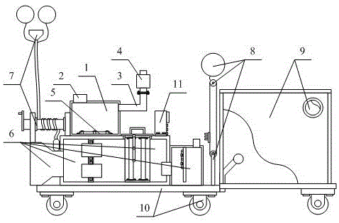
图1是本发明的结构示意图。Figure 1 is a schematic structural diagram of the present invention.
图2是本发明的气体过滤箱结构的结构示意图。FIG. 2 is a schematic structural diagram of the structure of the gas filter box of the present invention.
图3是本发明的漂浮气体收集管结构的结构示意图。FIG. 3 is a schematic structural diagram of the structure of the floating gas collection tube of the present invention.
图4是本发明的大气监测板结构的结构示意图。FIG. 4 is a schematic structural diagram of the structure of the atmospheric monitoring panel of the present invention.
图5是本发明的防护罩结构的结构示意图。FIG. 5 is a schematic structural diagram of the protective cover structure of the present invention.
图6是本发明的移动板结构的结构示意图。FIG. 6 is a schematic structural diagram of the moving plate structure of the present invention.
图7是本发明的控制器的结构示意图。FIG. 7 is a schematic structural diagram of the controller of the present invention.
图中:In the picture:
1、储药箱;2、进药头;3、出气管;4、第一风机;5、加热管;6、气体过滤箱结构;61、吸气箱;62、插接孔;63、竖立条;64、第二风机;65、吸气头;66、插接架;67、第一过滤网;68、拿放手柄;69、连通头;610、消毒壳;611、出气头;612、固定板;613、消毒灯;7、漂浮气体收集管结构;71、竖板;72、插接轴承;73、旋转杆;74、旋转手柄;75、第三风机;76、连接软管;77、吸风头;78、连接绳;79、第一氢气球;8、大气监测板结构;81、滑轮杆;82、下滑轮;83、升降绳;84、上滑轮;85、固定绳;86、第二氢气球;87、连接盘;88、传感器;9、防护罩结构;91、第一固定架;92、第二固定架;93、防护布;94、过滤管;95、第二过滤网;96、辅助轮;10、移动板结构;101、底板;102、移动轮;103、安装螺栓;104、推手;105、推杆;11、控制器;111、PLC;112、显示器;113、控制按键;114、安装块。1. Medicine storage box; 2. Inlet head; 3. Outlet pipe; 4. First fan; 5. Heating pipe; 6. Structure of gas filter box; 61. Suction box; Article; 64, the second fan; 65, the suction head; 66, the plug frame; 67, the first filter; 68, the handle; 69, the connecting head; 610, the disinfection shell; 611, the air outlet; 612, Fixed plate; 613, disinfection lamp; 7, floating gas collection pipe structure; 71, vertical plate; 72, plug bearing; 73, rotating rod; 74, rotating handle; 75, third fan; 76, connecting hose; 77 , suction head; 78, connecting rope; 79, first hydrogen balloon; 8, atmospheric monitoring board structure; 81, pulley rod; 82, lower pulley; 83, lifting rope; 84, upper pulley; 85, fixed rope; 86, The second hydrogen balloon; 87, the connecting plate; 88, the sensor; 9, the protective cover structure; 91, the first fixing frame; 92, the second fixing frame; 93, the protective cloth; 94, the filter tube; 95, the second filter screen ; 96, auxiliary wheel; 10, moving plate structure; 101, bottom plate; 102, moving wheel; 103, mounting bolt; 104, push handle; 105, push rod; 11, controller; 111, PLC; 112, display; 113, Control keys; 114. Mounting blocks.
具体实施方式Detailed ways
以下结合附图对本发明做进一步描述:The present invention will be further described below in conjunction with the accompanying drawings:
实施例:Example:
如附图1至附图7所示As shown in Figure 1 to Figure 7
本发明提供一种多功能的大气污染防治系统,包括储药箱1,进药头2,出气管3,第一风机4,加热管5,气体过滤箱结构6,漂浮气体收集管结构7,大气监测板结构8,防护罩结构9,移动板结构10和控制器11,所述的进药头2和出气管3分别焊接在储药箱1的左上部和右上部;所述的第一风机4法兰连接在出气管3的上端;所述的加热管5安装在储药箱1内部的下方;所述的气体过滤箱结构6上端与储药箱1焊接,下端与移动板结构10焊接;所述的漂浮气体收集管结构7分别与储药箱1的左端和气体过滤箱结构6的左上部焊接;所述的大气监测板结构8焊接在移动板结构10的右上部;所述的防护罩结构9焊接在移动板结构10的右端;所述的控制器11螺栓安装在气体过滤箱结构6的右上部;所述的气体过滤箱结构6包括吸气箱61,插接孔62,竖立条63,第二风机64,吸气头65,插接架66,第一过滤网67,拿放手柄68,连通头69,消毒壳610,出气头611,固定板612和消毒灯613,所述的吸气箱61左右两端分别焊接有吸气头65和消毒壳610;所述的竖立条63焊接在吸气箱61内壁的中左侧,并在正表面上螺栓安装有第二风机64;所述的第一过滤网67和拿放手柄68分别安装在插接架66的内壁和上端;所述的连通头69焊接在消毒壳610的左下部,并镶嵌在吸气箱61的右下部;所述的出气头611焊接在消毒壳610的右上部;所述的固定板612焊接在消毒壳610内壁上方的左侧,并在左表面上安装有消毒灯613。The present invention provides a multifunctional air pollution prevention and control system, including a medicine storage box 1, a medicine inlet 2, an air outlet pipe 3, a first fan 4, a heating pipe 5, a gas filter box structure 6, a floating gas collection pipe structure 7, The atmospheric monitoring board structure 8, the protective cover structure 9, the moving board structure 10 and the controller 11, the medicine inlet head 2 and the air outlet pipe 3 are welded to the upper left and upper right parts of the medicine storage box 1 respectively; the first The fan 4 is flanged on the upper end of the air outlet pipe 3; the heating pipe 5 is installed below the inside of the medicine storage box 1; the upper end of the gas filter box structure 6 is welded with the medicine storage box 1, and the lower end is connected with the moving plate structure 10 Welding; the floating gas collecting tube structure 7 is welded with the left end of the medicine storage box 1 and the upper left part of the gas filter box structure 6 respectively; the air monitoring plate structure 8 is welded on the upper right part of the moving plate structure 10; the The protective cover structure 9 is welded on the right end of the moving plate structure 10; the controller 11 is bolted to the upper right of the gas filter box structure 6; the gas filter box structure 6 includes a suction box 61, a plug hole 62 , erection bar 63, second fan 64, suction head 65, plug frame 66, first filter 67, handle 68, communication head 69, disinfection shell 610, air outlet head 611, fixed plate 612 and disinfection lamp 613 , the left and right ends of the suction box 61 are respectively welded with a suction head 65 and a sterilization shell 610; the vertical bar 63 is welded on the middle left side of the inner wall of the suction box 61, and the front surface is bolted with a No. Two
上述实施例中,具体的,所述的漂浮气体收集管结构7包括竖板71,插接轴承72,旋转杆73,旋转手柄74,第三风机75,连接软管76,吸风头77,连接绳78和第一氢气球79,所述的插接轴承72镶嵌在竖板71内壁的上方,并在内部插接有旋转杆73;所述的旋转手柄74焊接在旋转杆73的左端;所述的连接软管76上端与吸风头77胶接,下端缠绕在旋转杆73的外壁上,并与第三风机75连接;所述的连接绳78一端与连接软管76连接,另一端与第一氢气球79连接。In the above embodiment, specifically, the floating gas collecting
上述实施例中,具体的,所述的大气监测板结构8包括滑轮杆81,下滑轮82,升降绳83,上滑轮84,固定绳85,第二氢气球86,连接盘87和传感器88,所述的下滑轮82轴接在滑轮杆81的上端;所述的升降绳83套接在下滑轮82和上滑轮84之间;所述的固定绳85一端与上滑轮84连接,另一端与第二氢气球86连接;所述的连接盘87焊接在升降绳83的左端,并在左表面上安装有传感器88。In the above embodiment, specifically, the air
上述实施例中,具体的,所述的防护罩结构9包括第一固定架91,第二固定架92,防护布93,过滤管94,第二过滤网95和辅助轮96,所述的第二固定架92分别焊接在第一固定架91的左右两端;所述的过滤管94镶嵌在防护布93正表面的右上部,并在内部镶嵌有第二过滤网95;所述的辅助轮96分别螺栓安装在第一固定架91右下部的前后两侧。In the above embodiment, specifically, the
上述实施例中,具体的,所述的移动板结构10包括底板101,移动轮102,安装螺栓103,推手104和推杆105,所述的移动轮102分别通过安装螺栓103安装在底板101下表面的左右两侧;所述的推手104一端与底板101焊接,另一端与推杆105焊接。In the above embodiment, specifically, the moving
上述实施例中,具体的,所述的控制器11包括PLC111,显示器112,控制按键113和安装块114,所述的显示器112和控制按键113分别电性连接在PLC111的右表面;所述的安装块114分别焊接在PLC111前后两部的下侧。In the above-mentioned embodiment, specifically, the controller 11 includes a
上述实施例中,具体的,所述的插接架66具体采用回形不锈钢架,所述的插接架66穿过插接孔62并插接在吸气箱61内部的右侧;所述的插接架66内部的第一过滤网67设置有两个,所述的第一过滤网67分别采用活性炭滤网和HEPA滤网,有利于在完成收集气体后,可以方便的过滤收集来的有害气体,同时也增加了该大气污染治理系统的治理效果。In the above-mentioned embodiment, specifically, the plug-in
上述实施例中,具体的,所述的消毒灯613具体紫外线灯,所述的消毒灯613固定在固定板612的左表面,并与连通头69正对设置,有利于在完成过滤气体后,可以方便的对气体进行消毒,同时也增加了该气体过滤箱结构6进化的效果。In the above-mentioned embodiment, specifically, the
上述实施例中,具体的,所述的第一氢气球79设置有两个,所述的第一氢气球79分别通过连接绳78与连接软管76连接,所述的第一氢气球79下端与吸风头77上端之间的间距为五厘米至七厘米,有利于方便的使连接软管76停留在半空中,同时也方便的收集半空中的有害气体。In the above embodiment, specifically, there are two first hydrogen balloons 79, the first hydrogen balloons 79 are respectively connected with the connecting
上述实施例中,具体的,所述的旋转杆73插接在竖板71内壁上方的插接轴承72内,所述的旋转杆73外壁的右侧缠绕有连接软管76,所述的连接软管76下端的第三风机75与气体过滤箱结构6连接,有利于方便的收纳该漂浮气体收集管结构7,同时在收集气体后,可以方便的进行进化消毒的工作。In the above-mentioned embodiment, specifically, the rotating
上述实施例中,具体的,所述的上滑轮84通过固定绳85上的第二氢气球86处在半空中,所述的上滑轮84通过升降绳83限制住高度,所述的连接盘87与升降绳83胶接,有利于方便的使该大气监测板结构8的上部处在半空中,同时也方便的检测大气中不同位置的质量。In the above embodiment, specifically, the
上述实施例中,具体的,所述的连接盘87左表面上开设有多个螺纹孔,所述的连接盘87上的螺纹孔从上到下依次小一毫米至三毫米,所述的连接盘87左表面上安装有传感器88,所述的传感器88设置有多个,所述的传感器88分别采用大气环境传感器或者其它的传感器88,有利于方便的检测大气中不同的物质,同时也方便的达到防护检测的目的。In the above embodiment, specifically, the left surface of the connecting
上述实施例中,具体的,所述的第一固定架91和第二固定架92的内壁上分别胶接有防护布93,所述的防护布93具体采用PVC透明塑料布,所述的第二固定架92右表面的内壁上的防护布93上缝接有拉链,有利于方便的对工作人员起到防护的作用,同时也避免了工作人员在工作时吸入大量的有害气体,进一步有利于避免了容易对工作人员的身体健康造成伤害。In the above-mentioned embodiment, specifically, the inner walls of the
上述实施例中,具体的,所述的过滤管94内部的第二过滤网95具体采用活性炭过滤网,所述的过滤管94分别与防护布93内侧和外界连通,有利于方便的过滤进入到防护布93内侧的有害气体,同时也增加了该防护罩结构9的防护效果。In the above-mentioned embodiment, specifically, the
上述实施例中,具体的,所述的底板101下表面的移动轮102具体采用带有刹车片的万向轮,有利于方便的移动该移动板结构10,同时也方便的使该移动板结构10停留在合适的位置上。In the above-mentioned embodiment, specifically, the moving
上述实施例中,具体的,所述的推手104上部向右倾斜,所述的推手104上端的推杆105外壁上设置有一字防滑纹,有利于方便的推动该移动板结构10。In the above-mentioned embodiment, specifically, the upper part of the push handle 104 is inclined to the right, and the outer wall of the
上述实施例中,具体的,所述的PLC111分别与气体过滤箱结构6、漂浮气体收集管结构7和大气监测板结构8电性连接,有利于增加了该大气污染防治系统的智能化程度。In the above embodiment, specifically, the
上述实施例中,具体的,所述的PLC111具体采用型号为三菱FX2N-48的PLC。In the above-mentioned embodiment, specifically, the
工作原理working principle
本发明的工作原理:首先打开第二固定架92内壁防护布93上的拉链,然后使工作人进入到防护布93的内侧,再然后关闭防护布93上的拉链,同时工作人员握住推杆105并推动推手104,这样即可使底板101通过移动轮102移动到合适的位置,当到达合适位置后,使第二氢气球86升空,同时也将传感器88安装到连接盘87上,完成安装后,拉动升降绳83的右侧,并使连接盘87处在半空中,这样即可检测半空中的质量,完成检测后,启动第二风机64,并将有害的气体通过吸气头65吸入到吸气箱61内,当气体进入到吸气箱61内后通过第一过滤网67进行过滤,当完成过滤后,过滤的气体再通过连通头69进入到消毒壳610内通过消毒灯613进行消毒,当完成过滤和消毒后即可通过出气头611排放到空气中,当需要净化半空中的有害气体时,握住旋转手柄74然后使插接轴承72旋转放松连接软管76,同时放飞第一氢气球79并将放松部分的连接软管76处在半空中,最后使控制器11控制第三风机75启动,并将半空的有害气体通过吸风头77、连接软管76和第三风机75进入到气体过滤箱结构6内进行过滤消毒。The working principle of the present invention: first open the zipper on the
利用本发明所述的技术方案,或本领域的技术人员在本发明技术方案的启发下,设计出类似的技术方案,而达到上述技术效果的,均是落入本发明的保护范围。Using the technical solutions described in the present invention, or those skilled in the art design similar technical solutions under the inspiration of the technical solutions of the present invention, and achieve the above technical effects, all fall within the protection scope of the present invention.
Claims (9)
Priority Applications (1)
| Application Number | Priority Date | Filing Date | Title |
|---|---|---|---|
| CN201810071398.6A CN108201746B (en) | 2018-01-25 | 2018-01-25 | A multifunctional air pollution control system |
Applications Claiming Priority (1)
| Application Number | Priority Date | Filing Date | Title |
|---|---|---|---|
| CN201810071398.6A CN108201746B (en) | 2018-01-25 | 2018-01-25 | A multifunctional air pollution control system |
Publications (2)
| Publication Number | Publication Date |
|---|---|
| CN108201746A CN108201746A (en) | 2018-06-26 |
| CN108201746B true CN108201746B (en) | 2020-01-17 |
Family
ID=62606380
Family Applications (1)
| Application Number | Title | Priority Date | Filing Date |
|---|---|---|---|
| CN201810071398.6A Active CN108201746B (en) | 2018-01-25 | 2018-01-25 | A multifunctional air pollution control system |
Country Status (1)
| Country | Link |
|---|---|
| CN (1) | CN108201746B (en) |
Families Citing this family (2)
| Publication number | Priority date | Publication date | Assignee | Title |
|---|---|---|---|---|
| CN109381727A (en) * | 2018-12-04 | 2019-02-26 | 王璞 | A kind of farm's multifunctional spray disinfecting, deodorizing equipment |
| CN111220206A (en) * | 2019-12-02 | 2020-06-02 | 北京致感致联科技有限公司 | Offshore cursory formula fan wisdom monitoring system |
Family Cites Families (6)
| Publication number | Priority date | Publication date | Assignee | Title |
|---|---|---|---|---|
| US4702753A (en) * | 1986-04-21 | 1987-10-27 | Thaddeus Kowalczyk | Air purifier-combination filter |
| KR100445771B1 (en) * | 1995-01-20 | 2004-11-10 | 엥겔하드 코포레이션 | Method and apparatus for cleaning ambient air by contact with a stationary substrate |
| ATE300994T1 (en) * | 1995-09-29 | 2005-08-15 | Engelhard Corp | AMBIENT AIR PURIFICATION BY MOVING A VEHICLE CONTAINING A SURFACE FOR POLLUTION TREATMENT |
| CN102059160B (en) * | 2010-10-20 | 2013-04-03 | 中国人民解放军军事医学科学院微生物流行病研究所 | Biological safety protection cabin |
| CN204268606U (en) * | 2014-11-25 | 2015-04-15 | 中山市波信太阳能科技有限公司 | Air purification device and air filtration system with the device |
| CN105597436A (en) * | 2015-12-24 | 2016-05-25 | 张斌 | Collection treatment method and device for fugitive emission particulate matters |
-
2018
- 2018-01-25 CN CN201810071398.6A patent/CN108201746B/en active Active
Also Published As
| Publication number | Publication date |
|---|---|
| CN108201746A (en) | 2018-06-26 |
Similar Documents
| Publication | Publication Date | Title |
|---|---|---|
| CN203736563U (en) | Instrument disinfection device | |
| CN206545986U (en) | A kind of interior decoration air pollution processing unit | |
| CN108201746B (en) | A multifunctional air pollution control system | |
| CN108607854A (en) | A kind of textile machines dust-blowing device | |
| CN208186517U (en) | A kind of Multifunctional air sterilizer | |
| CN113587322B (en) | Ward air disinfection and air change equipment with detect alarming function | |
| CN104848429B (en) | A kind of indoor air purification equipment | |
| CN207138419U (en) | A kind of employee's dedusting sterilizing unit | |
| CN108050803A (en) | Medicinal material drying processes case | |
| CN213032139U (en) | A dust collector for textile processing | |
| CN208591638U (en) | The tail gas environment-friendly processing unit of vacuum paint-dipping machine drying equipment | |
| CN208911719U (en) | The waste gas treatment equipment of suspension fiber in a kind of removal air | |
| CN205867880U (en) | Automatic dust collector is used in flour processing | |
| CN105999944A (en) | Automatic dust removing device for flour processing | |
| CN108561977A (en) | A kind of air cleaning facility convenient for Laboratory air sterilization | |
| CN208115462U (en) | A kind of industrial emission-control equipment | |
| CN206838733U (en) | A kind of dust arrester of textile garment manufacturing equipment | |
| CN100394135C (en) | Air conditioner dust removal, disinfection and cleaning method and equipment | |
| CN204952478U (en) | But infrared remote control's air purification device | |
| CN220633493U (en) | Harmless treatment device for surgical smoke | |
| CN219572249U (en) | Intelligent robot with air purification function | |
| CN218924221U (en) | Exhaust gas purification environmental protection equipment capable of avoiding blockage | |
| CN204618970U (en) | Anorectal surgical exhaust apparatus | |
| CN214503519U (en) | Indoor empty gas detection surveys device of using convenient to remove and have processing function | |
| CN213611865U (en) | Water quenching device for nickel matte |
Legal Events
| Date | Code | Title | Description |
|---|---|---|---|
| PB01 | Publication | ||
| PB01 | Publication | ||
| SE01 | Entry into force of request for substantive examination | ||
| SE01 | Entry into force of request for substantive examination | ||
| GR01 | Patent grant | ||
| GR01 | Patent grant | ||
| TA01 | Transfer of patent application right |
Effective date of registration: 20191227 Address after: 311200 Room 601, building 3, No. 371, Mingxing Road, Xiaoshan Economic and Technological Development Zone, Xiaoshan District, Hangzhou City, Zhejiang Province Applicant after: Zhejiang zheneng mailing Environmental Technology Co.,Ltd. Address before: 250117 Huaiyin Road, Huaiyin District, Ji'nan, Shandong, Huaiyang road and Liu Chang Shan Road Interchange, greenbelt international Huadu 1-2 Applicant before: Zhang Kecai |
|
| TA01 | Transfer of patent application right | ||
| CP03 | Change of name, title or address |
Address after: Room 601, Building 3, No. 371 Mingxing Road, Xiaoshan Economic and Technological Development Zone, Xiaoshan District, Hangzhou City, Zhejiang Province, 311200 Patentee after: Zhejiang Zheneng Mailing Environmental Technology Co.,Ltd. Country or region after: China Address before: Room 601, Building 3, No. 371 Mingxing Road, Xiaoshan Economic and Technological Development Zone, Xiaoshan District, Hangzhou City, Zhejiang Province, 311200 Patentee before: Zhejiang zheneng mailing Environmental Technology Co.,Ltd. Country or region before: China |
|
| CP03 | Change of name, title or address | ||
| CP03 | Change of name, title or address |
Address after: 311200 Zhejiang Province, Hangzhou City, Xiaoshan District, Xiaoshan Economic and Technological Development Zone, No. 71 Jin'er Road, Building 5, 6th Floor (One License for Multiple Addresses) Patentee after: Zhejiang Zheneng Mailing Green Navigation Technology Co., Ltd. Country or region after: China Address before: Room 601, Building 3, No. 371 Mingxing Road, Xiaoshan Economic and Technological Development Zone, Xiaoshan District, Hangzhou City, Zhejiang Province, 311200 Patentee before: Zhejiang Zheneng Mailing Environmental Technology Co.,Ltd. Country or region before: China |
|
| CP03 | Change of name, title or address |