CN108242589B - Antenna structure and wireless communication device having the same - Google Patents

Antenna structure and wireless communication device having the same Download PDF

Info

Publication number
CN108242589B
CN108242589B CN201611206378.2A CN201611206378A CN108242589B CN 108242589 B CN108242589 B CN 108242589B CN 201611206378 A CN201611206378 A CN 201611206378A CN 108242589 B CN108242589 B CN 108242589B
Authority
CN
China
Prior art keywords
section
radiation
coupling
point
antenna
Prior art date
Legal status (The legal status is an assumption and is not a legal conclusion. Google has not performed a legal analysis and makes no representation as to the accuracy of the status listed.)
Expired - Fee Related
Application number
CN201611206378.2A
Other languages
Chinese (zh)
Other versions
CN108242589A (en
Inventor
刘建昌
曾顶志
宋昆霖
陈锡颉
赖鹏宇
Current Assignee (The listed assignees may be inaccurate. Google has not performed a legal analysis and makes no representation or warranty as to the accuracy of the list.)
Shenzhen Futaihong Precision Industry Co Ltd
Chiun Mai Communication Systems Inc
Original Assignee
Shenzhen Futaihong Precision Industry Co Ltd
Chiun Mai Communication Systems Inc
Priority date (The priority date is an assumption and is not a legal conclusion. Google has not performed a legal analysis and makes no representation as to the accuracy of the date listed.)
Filing date
Publication date
Application filed by Shenzhen Futaihong Precision Industry Co Ltd, Chiun Mai Communication Systems Inc filed Critical Shenzhen Futaihong Precision Industry Co Ltd
Priority to CN201611206378.2A priority Critical patent/CN108242589B/en
Priority to US15/835,401 priority patent/US10505262B2/en
Publication of CN108242589A publication Critical patent/CN108242589A/en
Application granted granted Critical
Publication of CN108242589B publication Critical patent/CN108242589B/en
Expired - Fee Related legal-status Critical Current
Anticipated expiration legal-status Critical

Links

Images

Classifications

    • HELECTRICITY
    • H01ELECTRIC ELEMENTS
    • H01QANTENNAS, i.e. RADIO AERIALS
    • H01Q1/00Details of, or arrangements associated with, antennas
    • H01Q1/36Structural form of radiating elements, e.g. cone, spiral, umbrella; Particular materials used therewith
    • HELECTRICITY
    • H01ELECTRIC ELEMENTS
    • H01QANTENNAS, i.e. RADIO AERIALS
    • H01Q1/00Details of, or arrangements associated with, antennas
    • H01Q1/12Supports; Mounting means
    • H01Q1/22Supports; Mounting means by structural association with other equipment or articles
    • H01Q1/24Supports; Mounting means by structural association with other equipment or articles with receiving set
    • H01Q1/241Supports; Mounting means by structural association with other equipment or articles with receiving set used in mobile communications, e.g. GSM
    • H01Q1/242Supports; Mounting means by structural association with other equipment or articles with receiving set used in mobile communications, e.g. GSM specially adapted for hand-held use
    • H01Q1/243Supports; Mounting means by structural association with other equipment or articles with receiving set used in mobile communications, e.g. GSM specially adapted for hand-held use with built-in antennas
    • HELECTRICITY
    • H01ELECTRIC ELEMENTS
    • H01QANTENNAS, i.e. RADIO AERIALS
    • H01Q1/00Details of, or arrangements associated with, antennas
    • H01Q1/48Earthing means; Earth screens; Counterpoises
    • HELECTRICITY
    • H01ELECTRIC ELEMENTS
    • H01QANTENNAS, i.e. RADIO AERIALS
    • H01Q1/00Details of, or arrangements associated with, antennas
    • H01Q1/50Structural association of antennas with earthing switches, lead-in devices or lightning protectors
    • HELECTRICITY
    • H01ELECTRIC ELEMENTS
    • H01QANTENNAS, i.e. RADIO AERIALS
    • H01Q21/00Antenna arrays or systems
    • H01Q21/28Combinations of substantially independent non-interacting antenna units or systems
    • HELECTRICITY
    • H01ELECTRIC ELEMENTS
    • H01QANTENNAS, i.e. RADIO AERIALS
    • H01Q5/00Arrangements for simultaneous operation of antennas on two or more different wavebands, e.g. dual-band or multi-band arrangements
    • H01Q5/30Arrangements for providing operation on different wavebands
    • H01Q5/307Individual or coupled radiating elements, each element being fed in an unspecified way
    • HELECTRICITY
    • H01ELECTRIC ELEMENTS
    • H01QANTENNAS, i.e. RADIO AERIALS
    • H01Q5/00Arrangements for simultaneous operation of antennas on two or more different wavebands, e.g. dual-band or multi-band arrangements
    • H01Q5/30Arrangements for providing operation on different wavebands
    • H01Q5/307Individual or coupled radiating elements, each element being fed in an unspecified way
    • H01Q5/342Individual or coupled radiating elements, each element being fed in an unspecified way for different propagation modes
    • H01Q5/35Individual or coupled radiating elements, each element being fed in an unspecified way for different propagation modes using two or more simultaneously fed points
    • HELECTRICITY
    • H01ELECTRIC ELEMENTS
    • H01QANTENNAS, i.e. RADIO AERIALS
    • H01Q5/00Arrangements for simultaneous operation of antennas on two or more different wavebands, e.g. dual-band or multi-band arrangements
    • H01Q5/30Arrangements for providing operation on different wavebands
    • H01Q5/307Individual or coupled radiating elements, each element being fed in an unspecified way
    • H01Q5/342Individual or coupled radiating elements, each element being fed in an unspecified way for different propagation modes
    • H01Q5/357Individual or coupled radiating elements, each element being fed in an unspecified way for different propagation modes using a single feed point
    • H01Q5/364Creating multiple current paths
    • H01Q5/371Branching current paths
    • HELECTRICITY
    • H01ELECTRIC ELEMENTS
    • H01QANTENNAS, i.e. RADIO AERIALS
    • H01Q9/00Electrically-short antennas having dimensions not more than twice the operating wavelength and consisting of conductive active radiating elements
    • H01Q9/04Resonant antennas
    • H01Q9/30Resonant antennas with feed to end of elongated active element, e.g. unipole
    • H01Q9/42Resonant antennas with feed to end of elongated active element, e.g. unipole with folded element, the folded parts being spaced apart a small fraction of the operating wavelength

Landscapes

  • Engineering & Computer Science (AREA)
  • Computer Networks & Wireless Communication (AREA)
  • Support Of Aerials (AREA)
  • Variable-Direction Aerials And Aerial Arrays (AREA)

Abstract

本发明提供一种天线结构,包括第一天线,所述第一天线包括第一馈入点,所述第一馈入点用以为所述第一天线馈入电流;第一辐射部,所述第一辐射部与所述第一馈入点电连接,用以接收第一频段的信号;第二辐射部,所述第二辐射部与所述第一馈入点电连接,且用以接收及发射第二频段的信号;以及第一接地点,所述第一接地点与所述第一馈入点间隔设置,且电连接至所述第二辐射部。上述天线结构具有较宽的频宽,可有效兼顾载波聚合(CA)功能,且具有较低的包络相关系数(ECC)。本发明还提供一种具有该天线结构的无线通信装置。
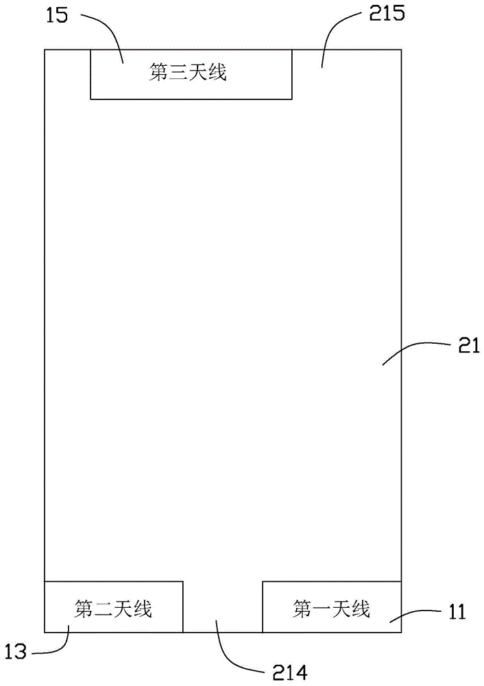
Figure 201611206378

The present invention provides an antenna structure, including a first antenna, the first antenna including a first feeding point, and the first feeding point is used to feed current to the first antenna; a first radiating part, the The first radiating part is electrically connected to the first feeding point for receiving signals of the first frequency band; the second radiating part is electrically connected to the first feeding point and used for receiving and transmitting a signal of a second frequency band; and a first ground point, the first ground point is spaced apart from the first feed point, and is electrically connected to the second radiation portion. The above antenna structure has a wider bandwidth, can effectively take into account the carrier aggregation (CA) function, and has a lower envelope correlation coefficient (ECC). The present invention also provides a wireless communication device with the antenna structure.

Figure 201611206378

Description

天线结构及具有该天线结构的无线通信装置Antenna structure and wireless communication device having the same

技术领域technical field

本发明涉及一种天线结构及具有该天线结构的无线通信装置。The present invention relates to an antenna structure and a wireless communication device having the antenna structure.

背景技术Background technique

随着无线通信技术的进步,无线通信装置不断朝向功能多样化、轻薄化、以及资料传输更快、更有效率等趋势发展,然而其相对可容纳天线的空间也就越来越小,而且随着长期演进(Long Term Evolution,LTE)技术的不断发展,天线的频宽不断增加。因此,如何在有限的空间内设计出具有较宽频宽的天线,是天线设计面临的一项重要课题。With the advancement of wireless communication technology, wireless communication devices continue to develop towards the trend of diversification of functions, thinner and lighter, and faster and more efficient data transmission. However, the space that can accommodate antennas is getting smaller and smaller, and with With the continuous development of the Long Term Evolution (Long Term Evolution, LTE) technology, the bandwidth of the antenna is continuously increasing. Therefore, how to design an antenna with a wider bandwidth in a limited space is an important issue faced by the antenna design.

发明内容SUMMARY OF THE INVENTION

有鉴于此,有必要提供一种具有较宽频宽的天线结构。In view of this, it is necessary to provide an antenna structure with a wider bandwidth.

另,有必要提供一种具有该天线结构的无线通信装置。In addition, it is necessary to provide a wireless communication device having this antenna structure.

一种天线结构,包括第一天线,所述第一天线包括:An antenna structure, comprising a first antenna, the first antenna comprising:

第一馈入点,所述第一馈入点用以为所述第一天线馈入电流;a first feeding point, the first feeding point is used to feed current to the first antenna;

第一辐射部,所述第一辐射部与所述第一馈入点电连接,用以接收第一频段的信号;a first radiating part, the first radiating part is electrically connected with the first feeding point, and is used for receiving the signal of the first frequency band;

第二辐射部,所述第二辐射部与所述第一馈入点电连接,且用以接收及发射第二频段的信号;以及a second radiating part, the second radiating part is electrically connected to the first feeding point, and is used for receiving and transmitting signals of the second frequency band; and

第一接地点,所述第一接地点与所述第一馈入点间隔设置,且电连接至所述第二辐射部。a first grounding point, the first grounding point is spaced apart from the first feeding point, and is electrically connected to the second radiating part.

一种无线通信装置,包括壳体及天线结构,所述壳体包括第一端部及第二端部,所述第二端部与所述第一端部相对设置,所述天线结构包括:A wireless communication device includes a casing and an antenna structure, the casing includes a first end and a second end, the second end is opposite to the first end, and the antenna structure includes:

第一天线,所述第一天线设置于所述第一端部,用于接收第一频段的信号,并接收及发射第二频段的信号;a first antenna, which is arranged at the first end and is used for receiving signals of the first frequency band, and receiving and transmitting signals of the second frequency band;

第二天线,所述第二天线设置于所述第一端部,且与所述第一天线间隔设置,所述第二天线用于接收及发射第三频段及第四频段的信号;以及a second antenna, the second antenna is disposed at the first end and spaced apart from the first antenna, and the second antenna is used for receiving and transmitting signals of the third frequency band and the fourth frequency band; and

第三天线,所述第三天线设置于所述第二端部,所述第三天线用于接收第五频段及第六频段的信号。A third antenna, the third antenna is disposed at the second end, and the third antenna is used for receiving signals of the fifth frequency band and the sixth frequency band.

上述天线结构及具有该天线结构的无线通信装置中的三个天线相互之间不会干扰,且每一个天线均可工作于至少两个频段,进而使得所述天线结构具有较宽的频宽,可有效兼顾长期演进技术升级版(LTE-Advanced)的载波聚合(CA,Carrier Aggregation)功能,且具有较低的包络相关系数(ECC)。再者,与传统的天线相比,该天线结构仅需设计三支天线,便可达到宽频设计,如此无需占用所述无线通信装置过多有限的空间,且使得其天线设计更具灵活性。The antenna structure and the three antennas in the wireless communication device with the antenna structure do not interfere with each other, and each antenna can operate in at least two frequency bands, so that the antenna structure has a wider frequency bandwidth, It can effectively take into account the carrier aggregation (CA, Carrier Aggregation) function of the Long Term Evolution (LTE-Advanced), and has a lower envelope correlation coefficient (ECC). Furthermore, compared with the traditional antenna, the antenna structure only needs to design three antennas to achieve a broadband design, which does not need to occupy too much limited space of the wireless communication device, and makes the antenna design more flexible.

附图说明Description of drawings

图1为本发明较佳实施例具有天线结构的无线通信装置的整体示意图。FIG. 1 is an overall schematic diagram of a wireless communication device having an antenna structure according to a preferred embodiment of the present invention.

图2为图1所示无线通信装置中第一天线、第二天线以及第三天线的位置示意图。FIG. 2 is a schematic diagram of the positions of the first antenna, the second antenna and the third antenna in the wireless communication device shown in FIG. 1 .

图3为图1所示无线通信装置的功能框图。FIG. 3 is a functional block diagram of the wireless communication device shown in FIG. 1 .

图4为图1所示天线结构中第一天线及第二天线的示意图。FIG. 4 is a schematic diagram of a first antenna and a second antenna in the antenna structure shown in FIG. 1 .

图5为图4所示天线结构中第一天线及第二天线另一角度下的示意图。FIG. 5 is a schematic diagram of the first antenna and the second antenna in the antenna structure shown in FIG. 4 from another angle.

图6为图1所示天线结构中第三天线的示意图。FIG. 6 is a schematic diagram of a third antenna in the antenna structure shown in FIG. 1 .

图7为图5所示天线结构中第一天线的散射参数曲线图。FIG. 7 is a graph showing the scattering parameters of the first antenna in the antenna structure shown in FIG. 5 .

图8为图5所示天线结构中第二天线的散射参数曲线图。FIG. 8 is a graph showing the scattering parameters of the second antenna in the antenna structure shown in FIG. 5 .

图9为图6所示天线结构中第三天线的散射参数曲线图。FIG. 9 is a graph showing the scattering parameters of the third antenna in the antenna structure shown in FIG. 6 .

图10为图5所示天线结构中第一天线的辐射效率曲线图。FIG. 10 is a graph showing the radiation efficiency of the first antenna in the antenna structure shown in FIG. 5 .

图11为图5所示天线结构中第二天线的辐射效率曲线图。FIG. 11 is a graph showing the radiation efficiency of the second antenna in the antenna structure shown in FIG. 5 .

图12为图6所示天线结构中第三天线的辐射效率曲线图。FIG. 12 is a radiation efficiency curve diagram of the third antenna in the antenna structure shown in FIG. 6 .

主要元件符号说明Description of main component symbols

天线结构 100Antenna Structure 100

第一天线 11first antenna 11

第一馈入点 110first feed point 110

第一辐射部 111The first radiation part 111

第二辐射部 112Second Radiation Section 112

第一接地点 113first ground point 113

第一辐射段 114first radiant segment 114

第二辐射段 115Second Radiant Segment 115

第三辐射段 116The third radiation segment 116

第四辐射段 117Fourth Radiant Segment 117

第五辐射段 118Fifth Radiant Segment 118

第六辐射段 119Sixth Radiant Segment 119

第七辐射段 120Seventh Radiant Segment 120

第一辐射臂 121first radiating arm 121

第二辐射臂 122Second Radial Arm 122

第二天线 13second antenna 13

第二馈入点 130Second feed point 130

第二接地点 131Second ground point 131

第一延伸部 132first extension 132

第二延伸部 133second extension 133

第一延伸段 134first extension 134

第二延伸段 135second extension 135

第三延伸段 136third extension 136

第四延伸段 137Fourth extension 137

第三天线 15third antenna 15

第三馈入点 150Third feed point 150

第三接地点 151Third ground point 151

第一耦合部 152first coupling part 152

第二耦合部 153second coupling part 153

第一耦合臂 154first coupling arm 154

第二耦合臂 155Second coupling arm 155

第三耦合臂 156Third coupling arm 156

第四耦合臂 157Fourth coupling arm 157

第五耦合臂 158Fifth coupling arm 158

第六耦合臂 159sixth coupling arm 159

第一耦合段 160first coupling segment 160

第二耦合段 161Second coupling segment 161

第三耦合段 162third coupling segment 162

无线通信装置 200Wireless communication device 200

壳体 21shell 21

背板 211Backplane 211

框体 212Frame 212

容置空间 213accommodating space 213

第一端部 214first end 214

第二端部 215second end 215

底壁 217Bottom wall 217

周壁 219Peripheral wall 219

凹槽 23Groove 23

承载部 25Carrier 25

第一表面 251first surface 251

第二表面 252second surface 252

如下具体实施方式将结合上述附图进一步说明本发明。The following specific embodiments will further illustrate the present invention with reference to the above drawings.

具体实施方式Detailed ways

下面将结合本发明实施例中的附图,对本发明实施例中的技术方案进行清楚、完整地描述,显然,所描述的实施例仅仅是本发明一部分实施例,而不是全部的实施例。基于本发明中的实施例,本领域普通技术人员在没有做出创造性劳动前提下所获得的所有其他实施例,都属于本发明保护的范围。The technical solutions in the embodiments of the present invention will be clearly and completely described below with reference to the accompanying drawings in the embodiments of the present invention. Obviously, the described embodiments are only a part of the embodiments of the present invention, but not all of the embodiments. Based on the embodiments of the present invention, all other embodiments obtained by those of ordinary skill in the art without creative efforts shall fall within the protection scope of the present invention.

需要说明的是,当一个元件被称为“电连接”另一个元件,它可以直接在另一个元件上或者也可以存在居中的元件。当一个元件被认为是“电连接”另一个元件,它可以是接触连接,例如,可以是导线连接的方式,也可以是非接触式连接,例如,可以是非接触式耦合的方式。It should be noted that when an element is referred to as being "electrically connected" to another element, it can be directly on the other element or intervening elements may also be present. When an element is considered to be "electrically connected" to another element, it can be a contact connection, eg, by means of a wire connection, or a contactless connection, eg, by a contactless coupling.

除非另有定义,本文所使用的所有的技术和科学术语与属于本发明的技术领域的技术人员通常理解的含义相同。本文中在本发明的说明书中所使用的术语只是为了描述具体的实施例的目的,不是旨在于限制本发明。本文所使用的术语“及/或”包括一个或多个相关的所列项目的任意的和所有的组合。Unless otherwise defined, all technical and scientific terms used herein have the same meaning as commonly understood by one of ordinary skill in the art to which this invention belongs. The terms used herein in the description of the present invention are for the purpose of describing specific embodiments only, and are not intended to limit the present invention. As used herein, the term "and/or" includes any and all combinations of one or more of the associated listed items.

下面结合附图,对本发明的一些实施方式作详细说明。在不冲突的情况下,下述的实施例及实施例中的特征可以相互组合。Some embodiments of the present invention will be described in detail below with reference to the accompanying drawings. The embodiments described below and features in the embodiments may be combined with each other without conflict.

请参阅图1,本发明较佳实施方式提供一种天线结构100,其应用于移动电话、个人数字助理等无线通信装置200中,用以发射、接收无线电波以传递、交换无线信号。Referring to FIG. 1, a preferred embodiment of the present invention provides an antenna structure 100, which is used in wireless communication devices 200 such as mobile phones and personal digital assistants for transmitting and receiving radio waves to transmit and exchange wireless signals.

该无线通信装置200还包括壳体21。所述壳体21可以为所述无线通信装置200的外观件。所述壳体21包括背板211及框体212。所述框体212及背板211可以是一体成型的。所述框体212环绕所述背板211的周缘设置,以与所述背板211共同围成一容置空间213(请参阅图5)。所述容置空间213用以容置所述无线通信装置200的基板、处理单元等电子元件或电路模块于其内。所述壳体21还包括第一端部214及第二端部215。在本实施例中,所述第一端部214为所述无线通信装置200的底部,其靠近所述无线通信装置200的通用串行总线(Universal Serial Bus,USB)接口模块(图未示)设置。所述第二端部215为所述无线通信装置200的顶部,其靠近所述无线通信装置200的摄像头模组(图未示)设置。另外,所述第一端部214背离所述容置空间213的表面形成有一凹槽23,以于所述第一端部214的位置形成一承载部25。所述承载部25与所述背板211共同形成一台阶状结构。在本实施例中,所述承载部25包括第一表面251及第二表面252。其中,所述承载部25对应所述背板211的部分为所述第一表面251。所述承载部25对应所述框体212的部分为所述第二表面252。The wireless communication device 200 also includes a housing 21 . The casing 21 may be an exterior part of the wireless communication device 200 . The casing 21 includes a back plate 211 and a frame body 212 . The frame body 212 and the back plate 211 may be integrally formed. The frame body 212 is disposed around the periphery of the back plate 211 to form an accommodating space 213 together with the back plate 211 (please refer to FIG. 5 ). The accommodating space 213 is used for accommodating electronic components or circuit modules such as the substrate and the processing unit of the wireless communication device 200 therein. The housing 21 further includes a first end portion 214 and a second end portion 215 . In this embodiment, the first end portion 214 is the bottom of the wireless communication device 200 , which is close to a Universal Serial Bus (USB) interface module (not shown) of the wireless communication device 200 . set up. The second end 215 is the top of the wireless communication device 200 , and is disposed close to the camera module (not shown) of the wireless communication device 200 . In addition, a groove 23 is formed on the surface of the first end portion 214 facing away from the accommodating space 213 to form a bearing portion 25 at the position of the first end portion 214 . The bearing portion 25 and the back plate 211 together form a stepped structure. In this embodiment, the bearing portion 25 includes a first surface 251 and a second surface 252 . The portion of the bearing portion 25 corresponding to the back plate 211 is the first surface 251 . The portion of the bearing portion 25 corresponding to the frame body 212 is the second surface 252 .

请一并参阅图2,所述天线结构100包括第一天线11、第二天线13及第三天线15。在本实施例中,所述第一天线11及第二天线13设置于所述第一端部214,且两者间隔设置。所述第三天线15设置于所述第二端部215,且与所述第一天线11及第二天线13均间隔设置。Please also refer to FIG. 2 , the antenna structure 100 includes a first antenna 11 , a second antenna 13 and a third antenna 15 . In this embodiment, the first antenna 11 and the second antenna 13 are disposed at the first end portion 214 and are disposed at intervals. The third antenna 15 is disposed at the second end 215 and is spaced apart from the first antenna 11 and the second antenna 13 .

具体地,在本实施例中,所述天线结构100中的第一天线11设置于所述无线通信装置200的右下角,即所述第一端部214的右侧。所述第二天线13设置于所述无线通信装置200的左下角,即所述第一端部214的左侧。所述第三天线15设置于所述无线通信装置200的顶部,即所述第二端部215的中部位置。当然,可以理解的是,所述第一天线11、第二天线13及第三天线15的位置不局限于上述所述,其还可根据具体情况进行相应调整,仅需保证所述第一天线11与所述第二天线13设置于所述无线通信装置200的底部,即第一端部214,所述第三天线15设置于所述无线通信装置200的顶部,即第二端部215即可。Specifically, in this embodiment, the first antenna 11 in the antenna structure 100 is disposed at the lower right corner of the wireless communication device 200 , that is, on the right side of the first end portion 214 . The second antenna 13 is disposed at the lower left corner of the wireless communication device 200 , ie, the left side of the first end portion 214 . The third antenna 15 is disposed on the top of the wireless communication device 200 , that is, in the middle of the second end 215 . Of course, it can be understood that the positions of the first antenna 11 , the second antenna 13 and the third antenna 15 are not limited to the above-mentioned ones, and they can also be adjusted according to the specific situation, and it is only necessary to ensure that the first antenna 11 and the second antenna 13 are arranged at the bottom of the wireless communication device 200, namely the first end 214, and the third antenna 15 is arranged at the top of the wireless communication device 200, namely the second end 215. Can.

请一并参阅图3,所述无线通信装置200还包括射频收发模块27。所述第一天线11、第二天线13以及第三天线15均与所述射频收发模块27电连接,以与所述射频收发模块27进行通信,进而实现无线信号的接收及发射。Please also refer to FIG. 3 , the wireless communication device 200 further includes a radio frequency transceiver module 27 . The first antenna 11 , the second antenna 13 and the third antenna 15 are all electrically connected to the radio frequency transceiver module 27 to communicate with the radio frequency transceiver module 27 , thereby realizing wireless signal reception and transmission.

请一并参阅图4及图5,在本实施例中,所述第一天线11设置于所述承载部25上。所述第一天线11包括第一馈入点110、第一辐射部111、第二辐射部112以及第一接地点113。所述第一馈入点110设置于所述第一表面251,且与所述射频收发模块27的信号馈入点(图未示)电连接,用以为所述第一天线11馈入电流信号。所述第一辐射部111为一副天线。所述第一辐射部111为一曲折状片体,其整体布设于所述第一表面251及第二表面252。所述第一辐射部111包括依次连接的第一辐射段114、第二辐射段115、第三辐射段116、第四辐射段117、第五辐射段118、第六辐射段119及第七辐射段120。所述第一辐射段114大致呈矩形条状,其布设于所述第一表面251且电连接至所述第一馈入点110。所述第二辐射段115大致呈矩形条状,其布设于所述第一表面251。所述第二辐射段115的一端垂直连接至所述第一辐射段114远离所述第一馈入点110的一端,并沿靠近所述第二表面252的方向延伸。Please refer to FIG. 4 and FIG. 5 together. In this embodiment, the first antenna 11 is disposed on the bearing portion 25 . The first antenna 11 includes a first feeding point 110 , a first radiating part 111 , a second radiating part 112 and a first grounding point 113 . The first feeding point 110 is disposed on the first surface 251 and is electrically connected to a signal feeding point (not shown) of the radio frequency transceiver module 27 for feeding a current signal to the first antenna 11 . The first radiation portion 111 is an antenna. The first radiating portion 111 is a zigzag sheet body, which is integrally arranged on the first surface 251 and the second surface 252 . The first radiation portion 111 includes a first radiation segment 114, a second radiation segment 115, a third radiation segment 116, a fourth radiation segment 117, a fifth radiation segment 118, a sixth radiation segment 119 and a seventh radiation segment, which are connected in sequence. segment 120. The first radiating section 114 is substantially in the shape of a rectangular strip, which is arranged on the first surface 251 and is electrically connected to the first feeding point 110 . The second radiating section 115 is substantially in the shape of a rectangular strip, which is arranged on the first surface 251 . One end of the second radiation section 115 is vertically connected to the end of the first radiation section 114 away from the first feeding point 110 and extends in a direction close to the second surface 252 .

所述第三辐射段116大致呈矩形条状,其布设于所述第二表面252。所述第三辐射段116的一端垂直连接至所述第二辐射段115远离所述第一辐射段114的一端,并沿平行所述第一辐射段114且靠近所述第一馈入点110的方向延伸。在本实施例中,所述第一辐射段114与所述第三辐射段116设置于所述第二辐射段115的同一侧。所述第一辐射段114、所述第二辐射段115与所述第三辐射段116共同形成大致呈U型的结构。在本实施例中,所述第一辐射段114的长度大于所述第三辐射段116的长度。The third radiating section 116 is substantially in the shape of a rectangular strip, which is arranged on the second surface 252 . One end of the third radiating section 116 is vertically connected to the end of the second radiating section 115 away from the first radiating section 114 , and is parallel to the first radiating section 114 and close to the first feeding point 110 extension in the direction. In this embodiment, the first radiation segment 114 and the third radiation segment 116 are disposed on the same side of the second radiation segment 115 . The first radiation segment 114 , the second radiation segment 115 and the third radiation segment 116 together form a substantially U-shaped structure. In this embodiment, the length of the first radiation segment 114 is greater than the length of the third radiation segment 116 .

所述第四辐射段117大致呈矩形条状,其布设于所述第一表面251。所述第四辐射段117的一端垂直连接至所述第三辐射段116远离所述第二辐射段115的一端,并沿平行所述第二辐射段115且靠近所述第一辐射段114的方向延伸。在本实施例中,所述第四辐射段117的长度小于所述第二辐射段115的长度。The fourth radiating section 117 is substantially in the shape of a rectangular strip, and is arranged on the first surface 251 . One end of the fourth radiation segment 117 is vertically connected to the end of the third radiation segment 116 away from the second radiation segment 115 , and is parallel to the second radiation segment 115 and close to the first radiation segment 114 . direction extension. In this embodiment, the length of the fourth radiation segment 117 is smaller than the length of the second radiation segment 115 .

所述第五辐射段118大致呈矩形条状,其布设于所述第一表面251。所述第五辐射段118的一端垂直连接至所述第四辐射段117远离所述第三辐射段116的一端,并沿平行所述第一辐射段114且靠近所述第二辐射段115的方向延伸。在本实施例中,所述第五辐射段118的长度小于所述第三辐射段116的长度。The fifth radiating section 118 is substantially in the shape of a rectangular strip, and is arranged on the first surface 251 . One end of the fifth radiation segment 118 is vertically connected to the end of the fourth radiation segment 117 away from the third radiation segment 116 , and is parallel to the first radiation segment 114 and close to the second radiation segment 115 . direction extension. In this embodiment, the length of the fifth radiation segment 118 is smaller than the length of the third radiation segment 116 .

所述第六辐射段119大致呈矩形条状,其布设于所述第一表面251。所述第六辐射段119的一端垂直连接至所述第五辐射段118远离所述第四辐射段117的一端,并沿平行所述第二辐射段115且靠近所述第一辐射段114的方向延伸。在本实施例中,所述第六辐射段119的长度小于所述第四辐射段117的长度。The sixth radiating section 119 is substantially in the shape of a rectangular strip, and is arranged on the first surface 251 . One end of the sixth radiation segment 119 is vertically connected to the end of the fifth radiation segment 118 away from the fourth radiation segment 117 , and is parallel to the second radiation segment 115 and close to the first radiation segment 114 . direction extension. In this embodiment, the length of the sixth radiation segment 119 is smaller than the length of the fourth radiation segment 117 .

所述第七辐射段120大致呈矩形条状,其一端垂直连接至所述第六辐射段119远离所述第五辐射段118的一端,并沿平行所述第一辐射段114且远离所述第二辐射段115的方向延伸。在本实施例中,所述第七辐射段120的长度大于所述第三辐射段116的长度,但小于所述第一辐射段114的长度。另外,所述第一辐射段114、第三辐射段116、第四辐射段117、第五辐射段118、第六辐射段119以及第七辐射段120均设置于所述第二辐射段115的同一侧。The seventh radiating section 120 is substantially in the shape of a rectangular strip, one end of which is vertically connected to the end of the sixth radiating section 119 away from the fifth radiating section 118, and is parallel to the first radiating section 114 and away from the The direction of the second radiation segment 115 extends. In this embodiment, the length of the seventh radiation segment 120 is greater than the length of the third radiation segment 116 but less than the length of the first radiation segment 114 . In addition, the first radiation segment 114 , the third radiation segment 116 , the fourth radiation segment 117 , the fifth radiation segment 118 , the sixth radiation segment 119 and the seventh radiation segment 120 are all disposed on the second radiation segment 115 . same side.

所述第二辐射部112为一主天线。所述第二辐射部112的整体长度小于所述第一辐射部111的长度。所述第二辐射部112包括第一辐射臂121及第二辐射臂122。所述第一辐射臂121布设于所述第一表面251上。所述第一辐射臂121的一端弧形过渡连接至所述第一馈入点110远离所述第一辐射段114的一侧,且沿远离所述第一辐射段114且靠近所述第二表面252的方向延伸。所述第二辐射臂122大致呈弧形片状,且布设于所述第二表面252上。所述第二辐射臂122的一端弧形过渡连接至所述第一辐射臂121远离所述第一馈入点110的一端,并沿靠近所述第三辐射段116的方向延伸。在本实施例中,所述第一辐射臂121的长度小于所述第二辐射臂122的长度。The second radiation portion 112 is a main antenna. The overall length of the second radiation portion 112 is smaller than the length of the first radiation portion 111 . The second radiation portion 112 includes a first radiation arm 121 and a second radiation arm 122 . The first radiation arm 121 is arranged on the first surface 251 . One end of the first radiating arm 121 is connected to the side of the first feeding point 110 away from the first radiating section 114 in an arc-shaped transition, and is further away from the first radiating section 114 and close to the second radiating section 114 . The direction of surface 252 extends. The second radiating arm 122 is generally in the shape of an arc and is arranged on the second surface 252 . One end of the second radiating arm 122 is connected to the end of the first radiating arm 121 away from the first feeding point 110 in an arc-shaped transition, and extends in a direction close to the third radiating section 116 . In this embodiment, the length of the first radiation arm 121 is smaller than the length of the second radiation arm 122 .

所述第一接地点113设置于所述第一辐射部111上。具体地,所述第一接地点113设置于所述第一辐射段114靠近所述第一辐射臂121的一端。所述第一接地点113与所述射频收发模块27的接地点(图未示)电连接,且电连接至所述第一辐射部111,进而为所述第一天线11提供接地。The first ground point 113 is disposed on the first radiation portion 111 . Specifically, the first ground point 113 is disposed at one end of the first radiation section 114 close to the first radiation arm 121 . The first ground point 113 is electrically connected to a ground point (not shown) of the radio frequency transceiver module 27 , and is electrically connected to the first radiation portion 111 , thereby providing grounding for the first antenna 11 .

可以理解,当电流自所述第一馈入点110馈入后,所述电流将依次流经所述第一辐射段114、第二辐射段115、第三辐射段116、第四辐射段117、第五辐射段118、第六辐射段119及第七辐射段120,并通过所述第一接地点113接地,进而使得所述第一辐射部111仅接收第一频段的信号。另外,流入所述第一馈入点110的电流还将流经所述第一辐射臂121及第二辐射臂122,进而使得所述第二辐射部112可接收及发射一第二频段的信号。在本实施例中,所述第一频段为一低频段,其频率范围为729-960MHz。所述第二频段为一高频段,其频率范围为2300-2700MHz。It can be understood that after the current is fed from the first feeding point 110 , the current will flow through the first radiation segment 114 , the second radiation segment 115 , the third radiation segment 116 , and the fourth radiation segment 117 in sequence , the fifth radiation segment 118 , the sixth radiation segment 119 and the seventh radiation segment 120 , and are grounded through the first ground point 113 , so that the first radiation portion 111 only receives signals of the first frequency band. In addition, the current flowing into the first feeding point 110 will also flow through the first radiating arm 121 and the second radiating arm 122 , so that the second radiating part 112 can receive and transmit a signal of a second frequency band . In this embodiment, the first frequency band is a low frequency band, and its frequency range is 729-960 MHz. The second frequency band is a high frequency band, and its frequency range is 2300-2700MHz.

请一并参阅图5,所述第二天线13设置于所述承载部25上,且与所述第一天线11间隔设置。所述第二天线13为一主天线。在本实施例中,所述第二天线13包括第二馈入点130、第二接地点131、第一延伸部132以及第二延伸部133。所述第二馈入点130设置于所述第一表面251。所述第二馈入点130设置于所述第一馈入点110远离所述第一接地点113的一侧,且与所述第一馈入点110间隔设置。所述第二馈入点130用以与所述射频收发模块27的信号馈入点电连接,以为所述第二天线13馈入电流信号。所述第二接地点131设置于所述第一表面251上,且位于所述第一馈入点110与所述第二馈入点130之间。所述第二接地点131用于与所述射频收发模块27的接地点电连接,以为所述第二天线13提供接地。Please also refer to FIG. 5 , the second antenna 13 is disposed on the carrying portion 25 and is spaced apart from the first antenna 11 . The second antenna 13 is a main antenna. In this embodiment, the second antenna 13 includes a second feed point 130 , a second ground point 131 , a first extension portion 132 and a second extension portion 133 . The second feeding point 130 is disposed on the first surface 251 . The second feed point 130 is disposed on a side of the first feed point 110 away from the first ground point 113 and is spaced from the first feed point 110 . The second feeding point 130 is used for electrically connecting with the signal feeding point of the radio frequency transceiver module 27 to feed the current signal to the second antenna 13 . The second ground point 131 is disposed on the first surface 251 and located between the first feeding point 110 and the second feeding point 130 . The second ground point 131 is used for electrically connecting with the ground point of the radio frequency transceiver module 27 to provide grounding for the second antenna 13 .

所述第一延伸部132大致呈矩形片状,且布设于所述第一表面251上。所述第一延伸部132垂直连接至所述第二馈入点130及第二接地点131的一端,且沿平行所述第二辐射段115且靠近所述第三辐射段116的方向延伸。在本实施例中,所述第一延伸部132的宽度大于所述第二辐射段115的宽度。The first extension portion 132 is substantially in the shape of a rectangular sheet, and is disposed on the first surface 251 . The first extension portion 132 is vertically connected to one end of the second feed point 130 and the second ground point 131 , and extends in a direction parallel to the second radiation segment 115 and close to the third radiation segment 116 . In this embodiment, the width of the first extension portion 132 is greater than the width of the second radiation segment 115 .

所述第二延伸部133包括依次连接的第一延伸段134、第二延伸段135、第三延伸段136以及第四延伸段137。所述第一延伸段134大致呈矩形条状,其布设于所述第一表面251。所述第一延伸段134的一端垂直连接至所述第二馈入点130远离所述第二接地点131的一侧,并沿平行所述第一延伸部132且远离所述第一辐射段114及第二辐射段115的方向延伸。所述第二延伸段135大致呈弧形片状,其布设于所述第一表面251。所述第二延伸段135的一端弧形连接至所述第一延伸段134远离所述第二馈入点130的一端,并沿平行所述第一辐射段114且靠近所述第二辐射段115的方向延伸。The second extension portion 133 includes a first extension section 134 , a second extension section 135 , a third extension section 136 and a fourth extension section 137 which are connected in sequence. The first extension section 134 is substantially in the shape of a rectangular strip, which is arranged on the first surface 251 . One end of the first extension section 134 is vertically connected to the side of the second feed point 130 away from the second ground point 131 , and is parallel to the first extension section 132 and away from the first radiation section 114 and the direction of the second radiation segment 115 extend. The second extension section 135 is generally in the shape of an arc and is arranged on the first surface 251 . One end of the second extension section 135 is arc-shaped connected to the end of the first extension section 134 away from the second feeding point 130 , and is parallel to the first radiation section 114 and close to the second radiation section 115 in the direction of extension.

所述第三延伸段136大致呈直条状,其布设于所述第一表面251。所述第三延伸段136的一端垂直连接至所述第二延伸段135远离所述第一延伸段134的一端,并沿平行所述第二辐射段115且靠近所述第二表面252的方向延伸。所述第四延伸段137大致呈弧形片状,其布设于所述第二表面252。所述第四延伸段137的一端垂直连接至所述第三延伸段136远离所述第二延伸段135的一端,并沿平行所述第二延伸段135且远离所述第三辐射段116的方向延伸。The third extending section 136 is substantially straight and is arranged on the first surface 251 . One end of the third extension section 136 is vertically connected to the end of the second extension section 135 away from the first extension section 134 , and is parallel to the second radiation section 115 and close to the second surface 252 extend. The fourth extension section 137 is substantially in the shape of an arc and is arranged on the second surface 252 . One end of the fourth extension section 137 is vertically connected to the end of the third extension section 136 away from the second extension section 135 , and is parallel to the second extension section 135 and away from the third radiating section 116 . direction extension.

在本实施例中,所述第二延伸部133的整体长度大于所述第一延伸部132的整体长度。当电流自所述第二馈入点130馈入后,所述电流将流经所述第一延伸部132,进而使得所述第一延伸部132可接收及发射第三频段的信号。另外,流入所述第二馈入点130的电流还将依次流经所述第二延伸部133的第一延伸段134、第二延伸段135、第三延伸段136以及第四延伸段137,并通过所述第二馈入点130接地,进而使得所述第二延伸部133可接收及发射第四频段的信号。在本实施例中,所述第三频段为一中频段,其频率范围为1710-2170MHz。所述第四频段为一低频段,其频率范围为824-894MHz。In this embodiment, the overall length of the second extension portion 133 is greater than the overall length of the first extension portion 132 . After the current is fed from the second feeding point 130 , the current will flow through the first extension portion 132 , so that the first extension portion 132 can receive and transmit signals of the third frequency band. In addition, the current flowing into the second feed point 130 will also flow through the first extension section 134 , the second extension section 135 , the third extension section 136 and the fourth extension section 137 of the second extension portion 133 in sequence. The second feed point 130 is grounded, so that the second extension portion 133 can receive and transmit signals of the fourth frequency band. In this embodiment, the third frequency band is an intermediate frequency band, and its frequency range is 1710-2170 MHz. The fourth frequency band is a low frequency band, and its frequency range is 824-894MHz.

请一并参阅图6,所述第三天线15为一副天线,其设置于所述容置空间213内。所述容置空间213包括底壁217及环绕所述底壁217设置的周壁219。所述第三天线15整体布设于所述底壁217上,并延伸至所述周壁219。所述第三天线15包括第三馈入点150、第三接地点151、第一耦合部152及第二耦合部153。所述第三馈入点150设置于所述底壁217上,且与所述射频收发模块27的信号馈入点电连接,用以为所述第三天线15馈入电流信号。所述第三接地点151设置于所述底壁217上,且与所述第三馈入点150间隔设置。所述第三接地点151与所述射频收发模块27的接地点电连接,用以为所述第三天线15提供接地。Please also refer to FIG. 6 , the third antenna 15 is a pair of antennas disposed in the accommodating space 213 . The accommodating space 213 includes a bottom wall 217 and a peripheral wall 219 surrounding the bottom wall 217 . The third antenna 15 is integrally arranged on the bottom wall 217 and extends to the peripheral wall 219 . The third antenna 15 includes a third feeding point 150 , a third grounding point 151 , a first coupling part 152 and a second coupling part 153 . The third feeding point 150 is disposed on the bottom wall 217 and is electrically connected to the signal feeding point of the radio frequency transceiver module 27 for feeding a current signal to the third antenna 15 . The third grounding point 151 is disposed on the bottom wall 217 and is spaced apart from the third feeding point 150 . The third ground point 151 is electrically connected to the ground point of the radio frequency transceiver module 27 to provide grounding for the third antenna 15 .

所述第一耦合部152包括第一耦合臂154、第二耦合臂155、第三耦合臂156、第四耦合臂157、第五耦合臂158以及第六耦合臂159。所述第一耦合臂154大致呈矩形条状,其一端电连接至所述第三馈入点150。所述第二耦合臂155大致呈矩形条状,其布设于所述容置空间213的底壁217上。所述第二耦合臂155的一端垂直连接至所述第一耦合臂154远离所述第三馈入点150的一端,并沿靠近所述容置空间213的周壁219的方向延伸。The first coupling part 152 includes a first coupling arm 154 , a second coupling arm 155 , a third coupling arm 156 , a fourth coupling arm 157 , a fifth coupling arm 158 and a sixth coupling arm 159 . The first coupling arm 154 is substantially in the shape of a rectangular strip, and one end of the first coupling arm 154 is electrically connected to the third feeding point 150 . The second coupling arm 155 is substantially in the shape of a rectangular strip, which is arranged on the bottom wall 217 of the accommodating space 213 . One end of the second coupling arm 155 is vertically connected to the end of the first coupling arm 154 away from the third feeding point 150 and extends in a direction close to the peripheral wall 219 of the accommodating space 213 .

所述第三耦合臂156大致呈矩形条状,其布设于所述容置空间213的底壁217上。所述第三耦合臂156的一端垂直连接至所述第二耦合臂155远离所述第一耦合臂154的一端,并沿平行所述第一耦合臂154且远离所述第三接地点151的方向延伸,直至越过所述第三馈入点150。在本实施例中,所述第三耦合臂156的长度大于所述第一耦合臂154的长度。所述第四耦合臂157大致呈矩形条状,其布设于所述容置空间213的周壁219上。所述第四耦合臂157的一端弧形过渡连接至所述第三耦合臂156远离所述第二耦合臂155的一端,并延伸至所述周壁219。The third coupling arm 156 is substantially in the shape of a rectangular strip, and is disposed on the bottom wall 217 of the accommodating space 213 . One end of the third coupling arm 156 is vertically connected to the end of the second coupling arm 155 away from the first coupling arm 154 , and is parallel to the first coupling arm 154 and away from the third ground point 151 . The direction extends until the third feeding point 150 is passed. In this embodiment, the length of the third coupling arm 156 is greater than the length of the first coupling arm 154 . The fourth coupling arm 157 is substantially in the shape of a rectangular strip, and is arranged on the peripheral wall 219 of the accommodating space 213 . One end of the fourth coupling arm 157 is connected to the end of the third coupling arm 156 away from the second coupling arm 155 in an arc-shaped transition, and extends to the peripheral wall 219 .

所述第五耦合臂158及第六耦合臂159均设置于所述容置空间213的周壁219。所述第五耦合臂158及第六耦合臂159均呈矩形条状。所述第五耦合臂158及第六耦合臂159的一端均垂直连接至所述第四耦合臂157远离所述第三耦合臂156的一端,并分别沿两个相反的方向延伸。在本实施例中,所述第五耦合臂158与所述第六耦合臂159的长度相当,且位于同一直线上,进而与所述第四耦合臂157共同构成大致呈T型的结构。The fifth coupling arm 158 and the sixth coupling arm 159 are both disposed on the peripheral wall 219 of the accommodating space 213 . The fifth coupling arm 158 and the sixth coupling arm 159 are both rectangular strips. One ends of the fifth coupling arm 158 and the sixth coupling arm 159 are both vertically connected to one end of the fourth coupling arm 157 away from the third coupling arm 156 and extend in two opposite directions respectively. In this embodiment, the fifth coupling arm 158 and the sixth coupling arm 159 have the same length and are located on the same straight line, and together with the fourth coupling arm 157 form a substantially T-shaped structure.

所述第二耦合部153整体布设于所述容置空间213的底壁217上。所述第二耦合部153包括依次连接的第一耦合段160、第二耦合段161及第三耦合段162。所述第一耦合段160大致呈矩形条状,其布设于所述容置空间213的底壁217上。所述第一耦合段160的一端电连接至所述第三接地点151,且沿远离所述第一耦合臂154的方向延伸。所述第二耦合段161大致呈矩形条状,其一端垂直连接至所述第一耦合段160远离所述第三接地点151的一端,并沿平行所述第二耦合臂155且靠近所述容置空间213的周壁219的方向延伸。所述第三耦合段162大致呈矩形条状,其一端垂直连接至所述第二耦合段161远离所述第一耦合段160的一端,并沿平行所述第一耦合段160且靠近所述第一耦合部152的方向延伸,直至垂直连接至所述第二耦合臂155与所述第三耦合臂156的连接处。The second coupling portion 153 is integrally arranged on the bottom wall 217 of the accommodating space 213 . The second coupling portion 153 includes a first coupling section 160 , a second coupling section 161 and a third coupling section 162 which are connected in sequence. The first coupling section 160 is substantially in the shape of a rectangular strip, and is arranged on the bottom wall 217 of the accommodating space 213 . One end of the first coupling section 160 is electrically connected to the third ground point 151 and extends in a direction away from the first coupling arm 154 . The second coupling section 161 is substantially in the shape of a rectangular strip, one end of which is vertically connected to the end of the first coupling section 160 away from the third ground point 151 , and is parallel to the second coupling arm 155 and close to the The direction of the peripheral wall 219 of the accommodating space 213 extends. The third coupling section 162 is substantially in the shape of a rectangular strip, and one end of the third coupling section 162 is vertically connected to the end of the second coupling section 161 away from the first coupling section 160, and is parallel to the first coupling section 160 and close to the The direction of the first coupling portion 152 extends until it is vertically connected to the connection between the second coupling arm 155 and the third coupling arm 156 .

在本实施例中,所述第一耦合部152的整体长度大于所述第二耦合部153的整体长度。当电流自所述第三馈入点150馈入后,所述电流将流经所述第一耦合臂154、第二耦合臂155、第三耦合臂156、第四耦合臂157以及第六耦合臂159,进而使得所述第一耦合部152仅接收第五频段的信号。另外,流入所述第三馈入点150的电流还将流经所述第一耦合臂154、第二耦合臂155、第三耦合臂156、第四耦合臂157以及第五耦合臂158,进而使得所述第一耦合部152仅接收第六频段的信号。在本实施例中,所述第五频段为一中频段,所述第六频段为一高频段。所述第五频段及第六频段的频率范围为1805-2690MHz。In this embodiment, the overall length of the first coupling portion 152 is greater than the overall length of the second coupling portion 153 . After the current is fed from the third feeding point 150, the current will flow through the first coupling arm 154, the second coupling arm 155, the third coupling arm 156, the fourth coupling arm 157 and the sixth coupling arm 159, so that the first coupling part 152 only receives the signal of the fifth frequency band. In addition, the current flowing into the third feeding point 150 will also flow through the first coupling arm 154 , the second coupling arm 155 , the third coupling arm 156 , the fourth coupling arm 157 and the fifth coupling arm 158 , and further So that the first coupling part 152 only receives the signal of the sixth frequency band. In this embodiment, the fifth frequency band is an intermediate frequency band, and the sixth frequency band is a high frequency band. The frequency range of the fifth frequency band and the sixth frequency band is 1805-2690 MHz.

图7为上述天线结构100中第一天线11的S参数(散射参数)曲线图。图8为上述天线结构100中第二天线13的S参数(散射参数)曲线图。图9为上述天线结构100中第三天线15的S参数(散射参数)曲线图。显然,由上述图7至图9可知,该天线结构100具有较佳的频宽,且满足天线设计要求。FIG. 7 is a graph showing the S-parameter (scattering parameter) of the first antenna 11 in the above-mentioned antenna structure 100 . FIG. 8 is a graph showing the S-parameter (scattering parameter) of the second antenna 13 in the above-mentioned antenna structure 100 . FIG. 9 is a graph showing the S-parameter (scattering parameter) of the third antenna 15 in the above-mentioned antenna structure 100 . Obviously, it can be seen from the above-mentioned FIG. 7 to FIG. 9 that the antenna structure 100 has a better frequency bandwidth and meets the antenna design requirements.

图10为上述天线结构100中第一天线11的辐射效率曲线图。图11为上述天线结构100中第二天线13的辐射效率曲线图。图12为上述天线结构100中第三天线15的辐射效率曲线图。显然,由上述图10至图12可知,当该天线结构100可工作于多个通信系统,且均具有较佳的辐射效率,满足一般天线的设计要求。FIG. 10 is a radiation efficiency curve diagram of the first antenna 11 in the above-mentioned antenna structure 100 . FIG. 11 is a graph showing the radiation efficiency of the second antenna 13 in the above-mentioned antenna structure 100 . FIG. 12 is a graph showing the radiation efficiency of the third antenna 15 in the above-mentioned antenna structure 100 . Obviously, as can be seen from the above-mentioned FIGS. 10 to 12 , when the antenna structure 100 can work in multiple communication systems, all of them have better radiation efficiency and meet the design requirements of general antennas.

请一并参阅下附表1,为所述天线结构100工作在各频率时的包络相关系数(ECC)值。显然,当所述天线结构100工作在各频段时,其均具有较低的包络相关系数ECC。Please also refer to the attached Table 1 below for the envelope correlation coefficient (ECC) values of the antenna structure 100 operating at various frequencies. Obviously, when the antenna structure 100 operates in each frequency band, it has a lower envelope correlation coefficient ECC.

表1天线结构100的包络相关系数(ECC)值TABLE 1 Envelope Correlation Coefficient (ECC) Values for Antenna Structure 100

频率(MHz)Frequency (MHz) ECCECC 频率(MHz)Frequency (MHz) ECCECC 734734 0.4700.470 18051805 0.0070.007 740740 0.4590.459 18431843 0.0030.003 746746 0.4260.426 18801880 0.0030.003 751751 0.4030.403 19301930 0.0090.009 756756 0.3950.395 19601960 0.0150.015 791791 0.1730.173 19901990 0.0200.020 806806 0.1770.177 21102110 0.0140.014 821821 0.1770.177 21402140 0.0270.027 869869 0.2470.247 21702170 0.0470.047 880880 0.2370.237 26202620 0.0410.041 894894 0.2170.217 26552655 0.0400.040 925925 0.1450.145 26902690 0.0360.036 942942 0.1120.112 960960 0.0760.076

显然,由于所述天线结构100中每一个天线都设置有单独的信号馈入点,例如第一天线11设置有第一馈入点110,第二天线13设置有第二馈入点130,第三天线15设置有第三馈入点150。如此,该三个天线相互之间不会干扰,且每一个天线均可工作于至少两个频段,进而使得所述天线结构100具有较宽的频宽,可有效兼顾长期演进技术升级版(LTE-Advanced)的载波聚合(CA,Carrier Aggregation)功能,且具有较低的包络相关系数(ECC)。再者,与传统的天线相比,该天线结构100仅需设计三支天线,便可达到宽频设计,如此无需占用所述无线通信装置200过多有限的空间,且使得其天线设计更具灵活性。Obviously, since each antenna in the antenna structure 100 is provided with a separate signal feed point, for example, the first antenna 11 is provided with a first feed point 110, the second antenna 13 is provided with a second feed point 130, and the first antenna 11 is provided with a first feed point 110. The three antennas 15 are provided with a third feeding point 150 . In this way, the three antennas do not interfere with each other, and each antenna can operate in at least two frequency bands, so that the antenna structure 100 has a wider frequency bandwidth, which can effectively take into account the long-term evolution technology upgrade (LTE). -Advanced) carrier aggregation (CA, Carrier Aggregation) function, and has a lower envelope correlation coefficient (ECC). Furthermore, compared with the conventional antenna, the antenna structure 100 only needs to design three antennas to achieve a broadband design, so that it does not need to occupy too much limited space of the wireless communication device 200 , and the antenna design is more flexible. sex.

可以理解,所述天线结构100中的第一天线11中的第二辐射部112及第二天线13均为主天线,如此可用以接收及发射相应频段的信号,例如所述第一天线11中的第二辐射部112及第二天线13可至少工作于第二频段(2300-2700MHz)、第三频段(1710-2170MHz)以及第四频段(824-894MHz),即所述第一天线11中的第二辐射部112及第二天线13可共同涵盖至低、中、高频,并具有较宽频宽。另外,所述天线结构100中的第三天线15为副天线,且所述第一天线11中的第一辐射部111亦承担副天线的功能,用以接收相应频段的信号,例如所述第一天线11中的第一辐射部111及第三天线15可至少工作于第一频段(729-960MHz)、第五频段以及第六频段(1805-2690MHz),即所述第一天线11中的第一辐射部111及第三天线15亦可共同涵盖至低、中、高频,并具有较宽频宽。It can be understood that the second radiating portion 112 and the second antenna 13 in the first antenna 11 in the antenna structure 100 are both main antennas, so that they can be used to receive and transmit signals in corresponding frequency bands. For example, in the first antenna 11 The second radiating part 112 and the second antenna 13 can work at least in the second frequency band (2300-2700MHz), the third frequency band (1710-2170MHz) and the fourth frequency band (824-894MHz), that is, in the first antenna 11 The second radiating portion 112 and the second antenna 13 can cover low, medium and high frequencies together, and have a wider bandwidth. In addition, the third antenna 15 in the antenna structure 100 is a sub-antenna, and the first radiating portion 111 in the first antenna 11 also assumes the function of a sub-antenna for receiving signals in corresponding frequency bands, such as the The first radiating portion 111 and the third antenna 15 in an antenna 11 can operate at least in the first frequency band (729-960MHz), the fifth frequency band and the sixth frequency band (1805-2690MHz), that is, in the first antenna 11 . The first radiating portion 111 and the third antenna 15 can also cover low, medium and high frequencies together, and have a wider bandwidth.

以上实施方式仅用以说明本发明的技术方案而非限制,尽管参照以上较佳实施方式对本发明进行了详细说明,本领域的普通技术人员应当理解,可以对本发明的技术方案进行修改或等同替换都不应脱离本发明技术方案的精神和范围。本领域技术人员还可在本发明精神内做其它变化等用在本发明的设计,只要其不偏离本发明的技术效果均可。这些依据本发明精神所做的变化,都应包含在本发明所要求保护的范围之内。The above embodiments are only used to illustrate the technical solutions of the present invention and not to limit them. Although the present invention has been described in detail with reference to the above preferred embodiments, those of ordinary skill in the art should understand that the technical solutions of the present invention can be modified or equivalently replaced. Neither should depart from the spirit and scope of the technical solutions of the present invention. Those skilled in the art can also make other changes within the spirit of the present invention to be used in the design of the present invention, as long as they do not deviate from the technical effects of the present invention. These changes made according to the spirit of the present invention should all be included within the scope of the claimed protection of the present invention.

Claims (20)

1. An antenna structure, characterized by: the antenna structure includes a first antenna and a second antenna, the first antenna includes:
a first feed point for feeding current to the first antenna;
the first radiation part is electrically connected with the first feed-in point and used for receiving signals of a first frequency band, and the first radiation part comprises a first radiation section, a second radiation section and a third radiation section which are sequentially connected;
the second radiation part is electrically connected with the first feed-in point and is used for receiving and transmitting signals of a second frequency band; and
the first grounding point and the first feed point are arranged at intervals and are electrically connected to the second radiation part;
the second antenna is arranged at an interval with the first antenna, the second antenna comprises a second feed point, a second grounding point and a first extension portion, the second feed point and the second grounding point are arranged at an interval, and the first extension portion is electrically connected to the second feed point and the second grounding point and extends along a direction parallel to the second radiation section and close to the third radiation section;
the second radiation part comprises a first radiation arm and a second radiation arm, one end of the first radiation arm is in arc transition connection with one side, far away from the first radiation section, of the first grounding point and extends along the direction far away from the first radiation section, and one end of the second radiation arm is in arc transition connection with one end, far away from the first grounding point, of the first radiation arm and extends along the direction close to the third radiation section.
2. The antenna structure of claim 1, characterized in that: the first radiation part further comprises a fourth radiation section, a fifth radiation section, a sixth radiation section and a seventh radiation section, the first radiation section is electrically connected to the first feed point, one end of the second radiation section is vertically connected to one end of the first radiation section far away from the first feed point, one end of the third radiation section is vertically connected to one end of the second radiation section far away from the first radiation section and extends along a direction parallel to the first radiation section and close to the first feed point, one end of the fourth radiation section is vertically connected to one end of the third radiation section far away from the second radiation section and extends along a direction parallel to the second radiation section and close to the first radiation section, one end of the fifth radiation section is vertically connected to one end of the fourth radiation section far away from the third radiation section and extends along a direction parallel to the first radiation section and close to the second radiation section, one end of the sixth radiation section is vertically connected to one end, far away from the fourth radiation section, of the fifth radiation section and extends along a direction parallel to the second radiation section and close to the first radiation section, and one end of the seventh radiation section is vertically connected to one end, far away from the fifth radiation section, of the sixth radiation section and extends along a direction parallel to the first radiation section and far away from the second radiation section.
3. The antenna structure of claim 2, characterized in that: the overall length of the second radiating portion is less than the length of the first radiating portion.
4. The antenna structure of claim 2, characterized in that: the second antenna further comprises a second extension portion, the second feed-in point is arranged on one side of the first feed-in point far away from the first grounding point and is arranged at an interval with the first feed-in point, the second grounding point is arranged between the first feed-in point and the second feed-in point, the first extension portion is used for receiving and transmitting signals of a third frequency band, and the second extension portion is electrically connected to the second feed-in point and is used for receiving and transmitting signals of a fourth frequency band.
5. The antenna structure of claim 4, characterized in that: the first extension part is vertically connected to the second grounding point and one end of the second feed-in point.
6. The antenna structure of claim 5, characterized in that: the second extending part comprises a first extending section, a second extending section, a third extending section and a fourth extending section which are connected in sequence, one end of the first extending section is vertically connected to one side of the second feed point far away from the second grounding point and extends along a direction parallel to the first extending part and far away from the first radiating section and the second radiating section, one end of the second extending section is connected to one end of the first extending section far away from the second feed point in an arc shape and extends along a direction parallel to the first radiating section and close to the second radiating section, one end of the third extending section is vertically connected to one end of the second extending section far away from the first extending section and extends along a direction parallel to the second radiating section and close to the third radiating section, and one end of the fourth extending section is vertically connected to one end of the third extending section far away from the second extending section, and extends in a direction parallel to the second extension segment and away from the third radiating segment.
7. The antenna structure of claim 4, characterized in that: the antenna structure further comprises a third antenna, the first antenna and the second antenna are arranged at intervals, the third antenna comprises a third feed point, a third grounding point, a first coupling portion and a second coupling portion, the first coupling portion is electrically connected with the third feed point, the second coupling portion is electrically connected with the third grounding point and the first coupling portion, and the first coupling portion is used for receiving wireless signals of a fifth frequency band and a sixth frequency band.
8. The antenna structure of claim 7, characterized in that: the frequency of the first frequency band is lower than the frequencies of the fifth frequency band and the sixth frequency band, the frequency of the second frequency band is higher than the frequency of the third frequency band, and the frequency of the third frequency band is higher than the frequency of the fourth frequency band.
9. The antenna structure of claim 7, characterized in that: the first coupling part comprises a first coupling arm, a second coupling arm, a third coupling arm, a fourth coupling arm, a fifth coupling arm and a sixth coupling arm, one end of the first coupling arm is electrically connected to the third feeding point, one end of the second coupling arm is perpendicularly connected to one end of the first coupling arm far away from the third feeding point, one end of the third coupling arm is perpendicularly connected to one end of the second coupling arm far away from the first coupling arm and extends along a direction parallel to the first coupling arm and far away from the third grounding point until crossing the third feeding point, one end of the fourth coupling arm is in arc transition connection with one end of the third coupling arm far away from the second coupling arm, one ends of the fifth coupling arm and the sixth coupling arm are perpendicularly connected to one end of the fourth coupling arm far away from the third coupling arm and extend along two opposite directions respectively, and then forms a T-shaped structure together with the fourth coupling arm.
10. The antenna structure of claim 9, characterized in that: the second coupling portion comprises a first coupling section, a second coupling section and a third coupling section which are sequentially connected, one end of the first coupling section is electrically connected to the third grounding point and extends along the direction far away from the first coupling arm, one end of the second coupling section is vertically connected to one end of the first coupling section far away from the third grounding point and extends along the direction parallel to the second coupling arm, and one end of the third coupling section is vertically connected to one end of the second coupling section far away from the first coupling section and extends along the direction parallel to the first coupling section and close to the first coupling portion until the third coupling section is vertically connected to the connection position of the second coupling arm and the third coupling arm.
11. A wireless communication device, comprising a housing and an antenna structure, the housing comprising a first end and a second end, the second end being disposed opposite the first end, the antenna structure comprising:
the first antenna is arranged at the first end part and used for receiving signals of a first frequency band and receiving and transmitting signals of a second frequency band;
the second antenna is arranged at the first end part and is arranged at an interval with the first antenna, and the second antenna is used for receiving and transmitting signals of a third frequency band and a fourth frequency band; and
a third antenna disposed at the second end, the third antenna being configured to receive signals of a fifth frequency band and a sixth frequency band;
the first antenna comprises a first feed point, a first radiation part, a second radiation part and a first grounding point, the first radiation part is electrically connected with the first feed point and comprises a first radiation section, a second radiation section and a third radiation section which are sequentially connected, the second radiation part is electrically connected with the first feed point, the first grounding point and the first feed point are arranged at intervals and are electrically connected with the second radiation part, the second radiation part comprises a first radiation arm and a second radiation arm, one end of the first radiation arm is in arc transition connection with one side of the first grounding point far away from the first radiation section and extends along the direction far away from the first radiation section, one end of the second radiation arm is in arc transition connection with one end of the first radiation arm far away from the first grounding point and extends along the direction close to the third radiation section, the second antenna comprises a second feed-in point, a second grounding point and a first extension portion, the second feed-in point and the second grounding point are arranged at intervals, and the first extension portion is electrically connected to the second feed-in point and the second grounding point and extends along a direction parallel to the second radiation section and close to the third radiation section.
12. The wireless communications apparatus of claim 11, wherein: the shell comprises a back plate and a frame body, the frame body is arranged around the periphery of the back plate to form an accommodating space together with the back plate, a groove is formed on the surface of the first end portion, which deviates from the accommodating space, so that a bearing portion is formed at the position of the first end portion, the first antenna and the second antenna are arranged on the bearing portion, and the third antenna is arranged in the accommodating space.
13. The wireless communications apparatus of claim 11, wherein: the frequency of the first frequency band is lower than the frequencies of the fifth frequency band and the sixth frequency band, the frequency of the second frequency band is higher than the frequency of the third frequency band, and the frequency of the third frequency band is higher than the frequency of the fourth frequency band.
14. The wireless communications apparatus of claim 11, wherein: the first radiation part further comprises a fourth radiation section, a fifth radiation section, a sixth radiation section and a seventh radiation section, the first radiation section is electrically connected to the first feed point, one end of the second radiation section is vertically connected to one end of the first radiation section far away from the first feed point, one end of the third radiation section is vertically connected to one end of the second radiation section far away from the first radiation section and extends along a direction parallel to the first radiation section and close to the first feed point, one end of the fourth radiation section is vertically connected to one end of the third radiation section far away from the second radiation section and extends along a direction parallel to the second radiation section and close to the first radiation section, one end of the fifth radiation section is vertically connected to one end of the fourth radiation section far away from the third radiation section and extends along a direction parallel to the first radiation section and close to the second radiation section, one end of the sixth radiation section is vertically connected to one end, far away from the fourth radiation section, of the fifth radiation section and extends along a direction parallel to the second radiation section and close to the first radiation section, and one end of the seventh radiation section is vertically connected to one end, far away from the fifth radiation section, of the sixth radiation section and extends along a direction parallel to the first radiation section and far away from the second radiation section.
15. The wireless communications apparatus of claim 14, wherein: the overall length of the second radiating portion is less than the length of the first radiating portion.
16. The wireless communications apparatus of claim 14, wherein: the second antenna further comprises a second extension portion, the second feed-in point is arranged on one side of the first feed-in point far away from the first grounding point and is arranged at an interval with the first feed-in point, the second grounding point is arranged between the first feed-in point and the second feed-in point, the first extension portion is used for receiving and transmitting the signal of the third frequency band, and the second extension portion is electrically connected to the second feed-in point and is used for receiving and transmitting the signal of the fourth frequency band.
17. The wireless communications apparatus of claim 16, wherein: the first extension part is vertically connected to one end of the second grounding point and the second feed point, the second extension part comprises a first extension section, a second extension section, a third extension section and a fourth extension section which are connected in sequence, one end of the first extension section is vertically connected to one side of the second feed point far away from the second grounding point and extends along a direction parallel to the first extension part and far away from the first radiation section and the second radiation section, one end of the second extension section is connected to one end of the first extension section far away from the second feed point in an arc shape and extends along a direction parallel to the first radiation section and close to the second radiation section, one end of the third extension section is vertically connected to one end of the second extension section far away from the first extension section and extends along a direction parallel to the second radiation section and close to the third radiation section, one end of the fourth extension segment is vertically connected to one end, far away from the second extension segment, of the third extension segment and extends along a direction parallel to the second extension segment and far away from the third radiation segment.
18. The wireless communications apparatus of claim 14, wherein: the third antenna comprises a third feed point, a third grounding point, a first coupling part and a second coupling part, wherein the first coupling part is electrically connected with the third feed point, the second coupling part is electrically connected with the third grounding point and the first coupling part, and the first coupling part is used for receiving wireless signals of a fifth frequency band and a sixth frequency band.
19. The wireless communications apparatus of claim 18, wherein: the first coupling part comprises a first coupling arm, a second coupling arm, a third coupling arm, a fourth coupling arm, a fifth coupling arm and a sixth coupling arm, one end of the first coupling arm is electrically connected to the third feeding point, one end of the second coupling arm is perpendicularly connected to one end of the first coupling arm far away from the third feeding point, one end of the third coupling arm is perpendicularly connected to one end of the second coupling arm far away from the first coupling arm and extends along a direction parallel to the first coupling arm and far away from the third grounding point until crossing the third feeding point, one end of the fourth coupling arm is in arc transition connection with one end of the third coupling arm far away from the second coupling arm, one ends of the fifth coupling arm and the sixth coupling arm are perpendicularly connected to one end of the fourth coupling arm far away from the third coupling arm and extend along two opposite directions respectively, and then forms a T-shaped structure together with the fourth coupling arm.
20. The wireless communications apparatus of claim 19, wherein: the second coupling portion comprises a first coupling section, a second coupling section and a third coupling section which are sequentially connected, one end of the first coupling section is electrically connected to the third grounding point and extends along the direction far away from the first coupling arm, one end of the second coupling section is vertically connected to one end of the first coupling section far away from the third grounding point and extends along the direction parallel to the second coupling arm, and one end of the third coupling section is vertically connected to one end of the second coupling section far away from the first coupling section and extends along the direction parallel to the first coupling section and close to the first coupling portion until the third coupling section is vertically connected to the connection position of the second coupling arm and the third coupling arm.
CN201611206378.2A 2016-12-23 2016-12-23 Antenna structure and wireless communication device having the same Expired - Fee Related CN108242589B (en)

Priority Applications (2)

Application Number Priority Date Filing Date Title
CN201611206378.2A CN108242589B (en) 2016-12-23 2016-12-23 Antenna structure and wireless communication device having the same
US15/835,401 US10505262B2 (en) 2016-12-23 2017-12-07 Antenna structure and wireless communication device using same

Applications Claiming Priority (1)

Application Number Priority Date Filing Date Title
CN201611206378.2A CN108242589B (en) 2016-12-23 2016-12-23 Antenna structure and wireless communication device having the same

Publications (2)

Publication Number Publication Date
CN108242589A CN108242589A (en) 2018-07-03
CN108242589B true CN108242589B (en) 2020-10-09

Family

ID=62630084

Family Applications (1)

Application Number Title Priority Date Filing Date
CN201611206378.2A Expired - Fee Related CN108242589B (en) 2016-12-23 2016-12-23 Antenna structure and wireless communication device having the same

Country Status (2)

Country Link
US (1) US10505262B2 (en)
CN (1) CN108242589B (en)

Cited By (1)

* Cited by examiner, † Cited by third party
Publication number Priority date Publication date Assignee Title
TWI851098B (en) 2023-03-21 2024-08-01 宏碁股份有限公司 Mobile device for reducing sar

Families Citing this family (9)

* Cited by examiner, † Cited by third party
Publication number Priority date Publication date Assignee Title
CN110828979B (en) * 2018-08-09 2021-12-28 深圳富泰宏精密工业有限公司 Antenna structure and wireless communication device with same
JP7120327B2 (en) * 2018-12-13 2022-08-17 ソニーグループ株式会社 antenna device
US10831690B2 (en) * 2019-01-14 2020-11-10 Sigmasense, Llc. Channel allocation among low voltage drive circuits
CN111799545B (en) * 2019-04-08 2022-01-14 Oppo广东移动通信有限公司 Antenna module and electronic equipment
CN111555018B (en) * 2020-05-20 2022-10-14 维沃移动通信有限公司 Electronic device
CN111555019B (en) * 2020-05-20 2022-07-12 维沃移动通信有限公司 Electronic device
CN113013592B (en) * 2021-02-24 2024-03-22 昆山睿翔讯通通信技术有限公司 Antenna and mobile communication equipment
TWI823424B (en) * 2022-06-14 2023-11-21 廣達電腦股份有限公司 Wearable device
TWI827294B (en) * 2022-10-04 2023-12-21 和碩聯合科技股份有限公司 Electronic device

Citations (2)

* Cited by examiner, † Cited by third party
Publication number Priority date Publication date Assignee Title
US20090009401A1 (en) * 2007-07-04 2009-01-08 Kabushiki Kaisha Toshiba Antenna device having no less than two antenna elements
CN105305028A (en) * 2015-10-16 2016-02-03 深圳市万普拉斯科技有限公司 Antenna structure of mobile terminal and mobile terminal

Family Cites Families (15)

* Cited by examiner, † Cited by third party
Publication number Priority date Publication date Assignee Title
KR100842082B1 (en) * 2006-12-05 2008-06-30 삼성전자주식회사 Antenna with additional ground
CN101414706A (en) * 2007-10-16 2009-04-22 华冠通讯股份有限公司 Multiband antenna device
CN101640307B (en) * 2008-07-30 2013-04-24 深圳富泰宏精密工业有限公司 Multi-frequency antenna and wireless communication device with same
US20100177005A1 (en) * 2009-01-15 2010-07-15 Cheng Uei Precision Industry Co., Ltd. Multi-Band Antenna
US8730110B2 (en) * 2010-03-05 2014-05-20 Blackberry Limited Low frequency diversity antenna system
CN201797038U (en) * 2010-07-09 2011-04-13 启碁科技股份有限公司 broadband antenna
JP2012160951A (en) 2011-02-01 2012-08-23 Toshiba Corp Multi-resonance antenna device, and electronic apparatus equipped with antenna device
US9673520B2 (en) * 2011-09-28 2017-06-06 Sony Corporation Multi-band wireless terminals with multiple antennas along an end portion, and related multi-band antenna systems
KR101378847B1 (en) * 2012-07-27 2014-03-27 엘에스엠트론 주식회사 Internal antenna with wideband characteristic
KR102081392B1 (en) * 2013-11-04 2020-02-25 삼성전자주식회사 An electronic device including an antenna apparatus
CN103762414B (en) * 2014-01-10 2016-08-17 瑞声光电科技(常州)有限公司 Antenna
US9520646B1 (en) * 2014-06-21 2016-12-13 Redpine Signals, Inc. Dual-band compact printed circuit antenna for WLAN use
TWI572096B (en) * 2015-12-04 2017-02-21 智易科技股份有限公司 Dual-band monopole antenna
CN205790353U (en) * 2016-06-14 2016-12-07 智慧海派科技有限公司 Downsizing broad-band antenna and the antenna assembly for mobile terminal
US10008782B2 (en) * 2016-06-24 2018-06-26 Huawei Technologies Co., Ltd. Low coupling full-duplex MIMO antenna array with coupled signal cancelling

Patent Citations (2)

* Cited by examiner, † Cited by third party
Publication number Priority date Publication date Assignee Title
US20090009401A1 (en) * 2007-07-04 2009-01-08 Kabushiki Kaisha Toshiba Antenna device having no less than two antenna elements
CN105305028A (en) * 2015-10-16 2016-02-03 深圳市万普拉斯科技有限公司 Antenna structure of mobile terminal and mobile terminal

Cited By (2)

* Cited by examiner, † Cited by third party
Publication number Priority date Publication date Assignee Title
TWI851098B (en) 2023-03-21 2024-08-01 宏碁股份有限公司 Mobile device for reducing sar
US12341262B2 (en) 2023-03-21 2025-06-24 Acer Incorporated Mobile device for reducing specific absorption rate

Also Published As

Publication number Publication date
US10505262B2 (en) 2019-12-10
CN108242589A (en) 2018-07-03
US20180183139A1 (en) 2018-06-28

Similar Documents

Publication Publication Date Title
CN108242589B (en) Antenna structure and wireless communication device having the same
CN103682630B (en) Communicator
TWI505562B (en) Wideband antenna
TWI662741B (en) Antenna structure and wireless communication device having the same
CN106816706B (en) Antenna structure and wireless communication device using the same
TWI628851B (en) Multi-frequency antenna structure
TWI656687B (en) Antenna structure and wireless communication device having the same
CN104752824A (en) Antenna structure and wireless communication device applying antenna structure
CN202352824U (en) Monopole antenna and electronic device
TW201539856A (en) Antenna structure and wireless communication device using the same
TWI630757B (en) Antenna structure and wireless communication device having the same
CN102683830A (en) Mobile communication device and antenna structure thereof
CN202159770U (en) Multi-frequency antenna structure
WO2020134328A1 (en) Antenna module and mobile terminal
CN111864350A (en) Antennas and Terminals
CN103972649B (en) Antenna module and the wireless communication device with the antenna module
CN112350053B (en) Antenna structure and wireless communication device having the same
CN103219581A (en) broadband antenna
TWI628847B (en) Antenna structure and wireless communication device using the same
TWI566472B (en) Antenna assembly
CN109980354A (en) Antenna structure and wireless communication device with the antenna structure
CN101777702B (en) Antenna Devices and Antennas
CN105633549B (en) Antenna structure and wireless communication device using the same
TWI694642B (en) Antenna module and wireless communication device using the antenna module
TWI587572B (en) Antenna structure

Legal Events

Date Code Title Description
PB01 Publication
PB01 Publication
SE01 Entry into force of request for substantive examination
GR01 Patent grant
GR01 Patent grant
CF01 Termination of patent right due to non-payment of annual fee

Granted publication date: 20201009

CF01 Termination of patent right due to non-payment of annual fee